Embed Size (px)
Citation preview
Strojarstvo 50 (6) 387-394 (2008) B. PAVKOVIĆ et. al., Analysis of Propane Thermal State... 387Analysis of Propane Thermal State... 387 387
CODEN STJSAO ISSN 0562-1887 ZX470/1363 UDK 536.2:519.87:621.6:539.4
Preliminary noteThe paper presents an analysis of annual variations of temperature and the corresponding saturation pressure of saturated liquid propane in a mounded cylindrical tank used for liquefied petroleum gas (LPG) storage. A mathematical model has been established based on a finite volume method. Boundary and initial conditions have been assumed for the Croatian climate. Simulations have been performed using the commercial CFD (Computational Fluid Dynamic) code on the representative numerical example. Analysis results have been presented through diagrams. It has been pointed out that the present regulation and practice for such tanks defines too high a design pressure of 1.64 MPa for the Croatian climate and that pressure of 1.2 MPa is sufficient to ensure proper design of such vessels. Significant simplifications and savings in production process can be achieved by changing the unnecessarily high design pressure.
Analiza toplinskoga stanja propana u zatrpanom spremniku s osvrtom na problematiku projektiranja
Prethodno priopćenjeU radu je prikazana analiza godišnjih promjena temperature i odgovarajućeg tlaka zasićenja zasićene kapljevine propana u zatrpanom cilindričnom spremniku kakav se koristi za skladištenje ukapljenog naftnog plina (UNP). Uspostavljen je matematički model baziran na metodi konačnih volumena. Rubni i početni uvjeti odgovaraju uvjetima klime u Hrvatskoj. Simulacije su provedene korištenjem komercijalnog CFD koda na reprezentativnom brojčanom primjeru. Rezultati analize su prikazani u dijagramima. Ukazano je na to da se za takve spremnike po važećim propisima i praksi koristi previsok projektni tlak od 1.64 MPa za hrvatske klimatske uvjete i da je tlak od 1.2 MPa dovoljan da se osigura ispravno dimenzioniranje ovakvih spremnika. Značajna pojednostavljenja i uštede u procesu proizvodnje mogu se ostvariti promjenom nepotrebno visokog projektnog radnog tlaka.
Branimir PAVKOViĆ1), Zoran ČARiJA1)
and ivan SAMARDŽiĆ2)
1) Tehnički fakultet, Sveučilišta u Rijeci (University of Rijeka Faculty of Engineering), Vukovarska 58 HR - 51000 Rijeka Republic of Croatia
2) Strojarski fakultet u Slavonskom Brodu, Sveučilište u Osijeku, Trg Ivane Brlić Mažuranić 2, HR - 35000 Slavonski Brod Republic of Croatia
KeywordsCylindrical pressure vessels Heat transfer Mathematical modelling Pressure Simulation Tank design Temperature
Ključne riječiCilindrične tlačne posude Dimenzioniranje spremnika Matematičko modeliranje Prijelaz topline Simulacija Temperatura Tlak
Received (primljeno): 2007-11-15 Accepted (prihvaćeno): 2008-11-25
Analysis of Propane Thermal State in Underground Tanks Taking Into Consideration Design Issues
1. Introduction
Cylindrical and spherical pressure vessels are used for storing liquefied petrol gas (LPG). Due to a large volume, the stored medium has huge potential energy, and it can be dangerous for the environment. Therefore, all phases of the design, production and use of these pressure vessels are subject to inspection and controls. Design pressures for such vessels are defined by local regulations and practice imposed by competent inspectorate. Present Croatian regulation assumed from former state [1, 2] defines the design pressure which is equal to saturation pressure of liquid gas at 40 oC. In the case of LPG storage, pure
propane has to be considered as stored gas and propane saturation pressure at 40 oC, which is equal to 1,4 MPa, has to be accounted for. When the tank is exposed to the ambient temperature and solar radiation, temperatures of gas inside the tank can be higher and the design pressure of 1,64 MPa is appropriate. Nevertheless design pressure of 1,64 MPa is required by authorities for the design of all vessels used for LPG storage, without distinction between underground vessels (mounded or buried) and vessels exposed to environmental influences. In some other countries such a distinction is usual. For example, older German regulation [3] defined temperature of 30 oC as the liquid gas saturation temperature used for
388 B. PAVKOVIĆ et. al., Analysis of Propane Thermal State... Strojarstvo 50 (6) 387-394 (2008)
Symbols/Oznake
a - absorption coefficient for radiation - koeficijent apsorpcije zračenja δ - wall thickness, mm
- debljina stijenkec - specific thermal capacity, J/kg·K
- specifični toplinski kapacitet λ - thermal conductivity, W/m·K- toplinska vodljivost
D - diameter, m- promjer μ - dynamic viscosity, Pa·s
- dinamička viskoznostE - energy, J
- energija ρ - density, kg/m3
- gustoćag - gravitational acceleration, m/s2
- ubrzanje teže- temperature, °C- temperatura
I - solar irradiation, W/m2
- dozračena sunčeva energija Indices / Indeksi
K - design stress, Pa- dozvoljeno projektno naprezanje a - outside air
- vanjski zrakp - pressure, Pa
- tlak e - external- vanjski
q - heat flux, W/m2
- toplinski tok eff - effective- efektivni
t - time, s- vrijeme i - internal
- unutarnjiSh - energy of heat source, J
- energija toplinskog izvora l - liquid- kapljevina
T - thermodynamic temperature, K- termodinamička temperatura p - at constant pressure
- kod konstantnog tlakav - velocity, (m/s)
- brzina s - solar- sunčeva
w - weld joint factor- faktor zavara sur - surface
- površinskaα - heat transfer coefficient, W/m2K
- koeficijent prijelaza topline ν - vapor- para
calculation of the design pressure in the case when the vessel is covered by a soil layer of minimal thicknes higher than 0,5 m. A similar approach can be found in American regulations, such as NFPA 58 [4] where a distinction between underground and surface placed vessels is made. It is well known that the soil temperature variations, caused by outside air temperature and solar radiation, diminish with the depth of the soil. At soil depths below 15 m, temperature variations practically disappear [5, 6]. The intention of the presented analysis is to determine temperatures and saturation pressures within the cylindrical tank used for underground storage of LPG covered by a 0,7 or 1,0 m thick layer of sand and clay, which is the usual way of covering such tanks, and to find out extreme pressures which can appear in such case during the test reference year for analyzed locations. This case study analyzes 500 m3 cylindrical tanks used in a 2 500 m3 LPG storage array. Strength calculations and tank design performed according to [7] lead to a reduction in tank thickness of approximately 4 mm in the case of
design pressure 1,22 MPa compared to the case with a design pressure of 1,66 MPa. Such a decrease in thickness results in reduction of used steel mass of approximately 14 000 kg per tank or 70 000 kg for the entire storage for the considered case. Such a mass reduction is connected with material and production costs and financial benefits of design pressure reduction are obvious.
2. Problem modelling
2.1. Problem geometry, materials and boundary conditions
Properties of liquefied petrol gas LPG, which is usually a compound of 60 % of butane mass fraction and 40 % of propane mass fraction, depend on temperature. In order to find the highest possible pressure and to avoid calculating the internal pressure of LPG, only the propane component has been considered. Propane has
Strojarstvo 50 (6) 387-394 (2008) B. PAVKOVIĆ et. al., Analysis of Propane Thermal State... 389Analysis of Propane Thermal State... 389 389
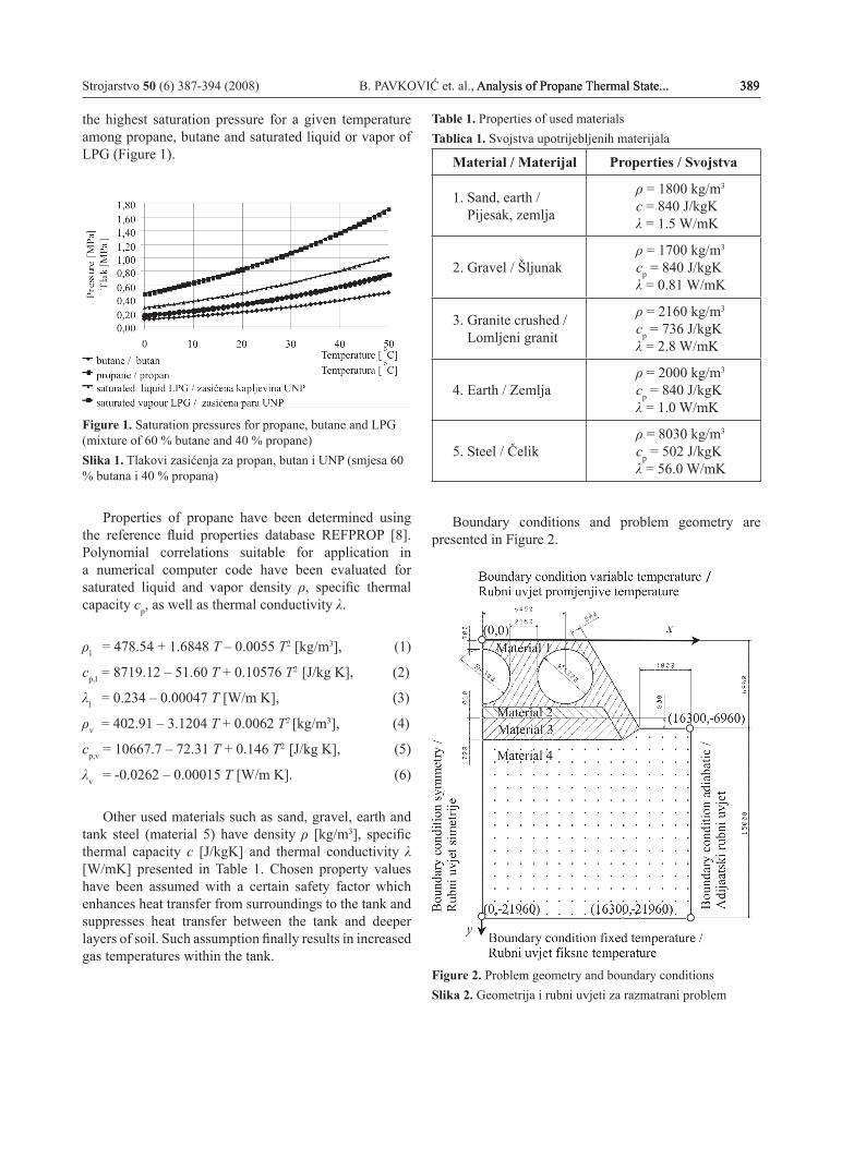
the highest saturation pressure for a given temperature among propane, butane and saturated liquid or vapor of LPG (Figure 1).
Figure 1. Saturation pressures for propane, butane and LPG (mixture of 60 % butane and 40 % propane)Slika 1. Tlakovi zasićenja za propan, butan i UNP (smjesa 60 % butana i 40 % propana)
Properties of propane have been determined using the reference fluid properties database REFPROP [8]. Polynomial correlations suitable for application in a numerical computer code have been evaluated for saturated liquid and vapor density ρ, specific thermal capacity cp, as well as thermal conductivity λ.
ρl = 478.54 + 1.6848 T – 0.0055 T2 [kg/m3], (1)
cp,l = 8719.12 – 51.60 T + 0.10576 T2 [J/kg K], (2)
λl = 0.234 – 0.00047 T [W/m K], (3)
ρv = 402.91 – 3.1204 T + 0.0062 T2 [kg/m3], (4)
cp,v = 10667.7 – 72.31 T + 0.146 T2 [J/kg K], (5)
λv = -0.0262 – 0.00015 T [W/m K]. (6)
Other used materials such as sand, gravel, earth and tank steel (material 5) have density ρ [kg/m3], specific thermal capacity c [J/kgK] and thermal conductivity λ [W/mK] presented in Table 1. Chosen property values have been assumed with a certain safety factor which enhances heat transfer from surroundings to the tank and suppresses heat transfer between the tank and deeper layers of soil. Such assumption finally results in increased gas temperatures within the tank.
Table 1. Properties of used materials Tablica 1. Svojstva upotrijebljenih materijala
Material / Materijal Properties / Svojstva
1. Sand, earth / Pijesak, zemlja
ρ = 1800 kg/m3
c = 840 J/kgKλ = 1.5 W/mK
2. Gravel / Šljunakρ = 1700 kg/m3
cp = 840 J/kgKλ = 0.81 W/mK
3. Granite crushed / Lomljeni granit
ρ = 2160 kg/m3
cp = 736 J/kgKλ = 2.8 W/mK
4. Earth / Zemljaρ = 2000 kg/m3
cp = 840 J/kgKλ = 1.0 W/mK
5. Steel / Čelikρ = 8030 kg/m3
cp = 502 J/kgKλ = 56.0 W/mK
Boundary conditions and problem geometry are presented in Figure 2.
Figure 2. Problem geometry and boundary conditionsSlika 2. Geometrija i rubni uvjeti za razmatrani problem
390 B. PAVKOVIĆ et. al., Analysis of Propane Thermal State... Strojarstvo 50 (6) 387-394 (2008)
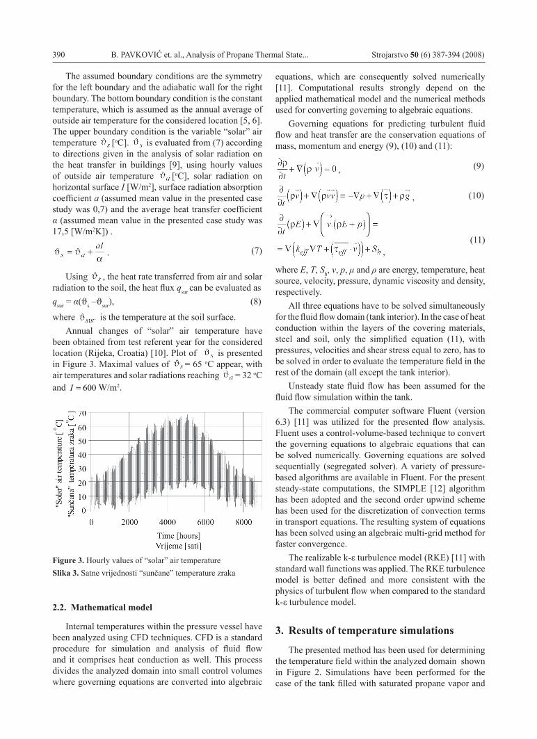
The assumed boundary conditions are the symmetry for the left boundary and the adiabatic wall for the right boundary. The bottom boundary condition is the constant temperature, which is assumed as the annual average of outside air temperature for the considered location [5, 6]. The upper boundary condition is the variable “solar” air temperature [oC]. is evaluated from (7) according to directions given in the analysis of solar radiation on the heat transfer in buildings [9], using hourly values of outside air temperature [oC], solar radiation on horizontal surface I [W/m2], surface radiation absorption coefficient a (assumed mean value in the presented case study was 0,7) and the average heat transfer coefficient α (assumed mean value in the presented case study was 17,5 [W/m2K]) .
.
(7)
Using , the heat rate transferred from air and solar radiation to the soil, the heat flux qsur can be evaluated as qsur = α(ϑs –ϑsur), (8)
where is the temperature at the soil surface. Annual changes of “solar” air temperature have
been obtained from test referent year for the considered location (Rijeka, Croatia) [10]. Plot of is presented in Figure 3. Maximal values of = 65 oC appear, with air temperatures and solar radiations reaching = 32 oC and 600=I W/m2.
Figure 3. Hourly values of “solar” air temperatureSlika 3. Satne vrijednosti “sunčane” temperature zraka
2.2. Mathematical model
Internal temperatures within the pressure vessel have been analyzed using CFD techniques. CFD is a standard procedure for simulation and analysis of fluid flow and it comprises heat conduction as well. This process divides the analyzed domain into small control volumes where governing equations are converted into algebraic
equations, which are consequently solved numerically [11]. Computational results strongly depend on the applied mathematical model and the numerical methods used for converting governing to algebraic equations.
Governing equations for predicting turbulent fluid flow and heat transfer are the conservation equations of mass, momentum and energy (9), (10) and (11):
,
(9)
,
(10)
(11)
where E, T, Sh, v, p, μ and ρ are energy, temperature, heat source, velocity, pressure, dynamic viscosity and density, respectively.
All three equations have to be solved simultaneously for the fluid flow domain (tank interior). In the case of heat conduction within the layers of the covering materials, steel and soil, only the simplified equation (11), with pressures, velocities and shear stress equal to zero, has to be solved in order to evaluate the temperature field in the rest of the domain (all except the tank interior).
Unsteady state fluid flow has been assumed for the fluid flow simulation within the tank.
The commercial computer software Fluent (version 6.3) [11] was utilized for the presented flow analysis. Fluent uses a control-volume-based technique to convert the governing equations to algebraic equations that can be solved numerically. Governing equations are solved sequentially (segregated solver). A variety of pressure-based algorithms are available in Fluent. For the present steady-state computations, the SIMPLE [12] algorithm has been adopted and the second order upwind scheme has been used for the discretization of convection terms in transport equations. The resulting system of equations has been solved using an algebraic multi-grid method for faster convergence.
The realizable k-ε turbulence model (RKE) [11] with standard wall functions was applied. The RKE turbulence model is better defined and more consistent with the physics of turbulent flow when compared to the standard k-ε turbulence model.
3. Results of temperature simulations
The presented method has been used for determining the temperature field within the analyzed domain shown in Figure 2. Simulations have been performed for the case of the tank filled with saturated propane vapor and
,
Strojarstvo 50 (6) 387-394 (2008) B. PAVKOVIĆ et. al., Analysis of Propane Thermal State... 391Analysis of Propane Thermal State... 391 391
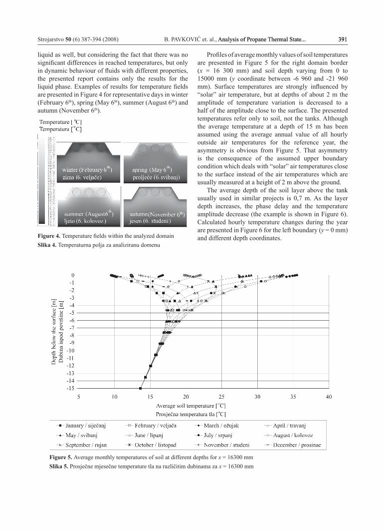
liquid as well, but considering the fact that there was no significant differences in reached temperatures, but only in dynamic behaviour of fluids with different properties, the presented report contains only the results for the liquid phase. Examples of results for temperature fields are presented in Figure 4 for representative days in winter (February 6th), spring (May 6th), summer (August 6th) and autumn (November 6th).
Figure 4. Temperature fields within the analyzed domain Slika 4. Temperaturna polja za analiziranu domenu
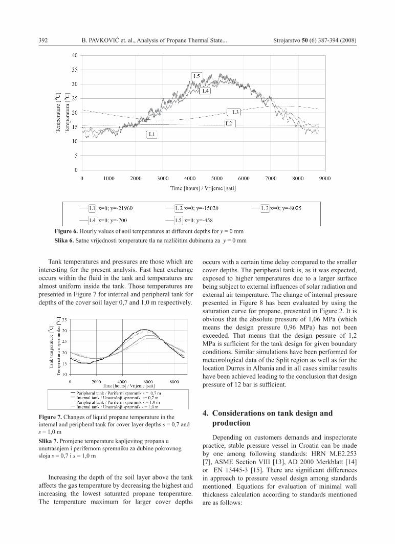
Profiles of average monthly values of soil temperatures are presented in Figure 5 for the right domain border (x = 16 300 mm) and soil depth varying from 0 to 15000 mm (y coordinate between -6 960 and -21 960 mm). Surface temperatures are strongly influenced by “solar” air temperature, but at depths of about 2 m the amplitude of temperature variation is decreased to a half of the amplitude close to the surface. The presented temperatures refer only to soil, not the tanks. Although the average temperature at a depth of 15 m has been assumed using the average annual value of all hourly outside air temperatures for the reference year, the asymmetry is obvious from Figure 5. That asymmetry is the consequence of the assumed upper boundary condition which deals with “solar” air temperatures close to the surface instead of the air temperatures which are usually measured at a height of 2 m above the ground.
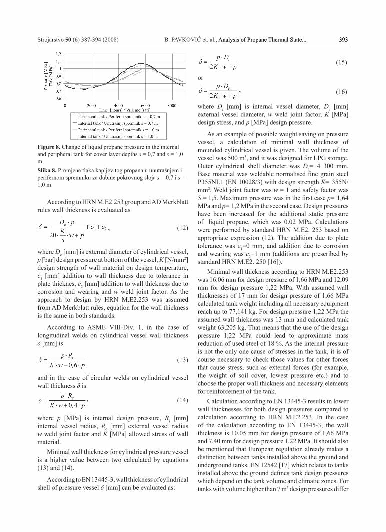
The average depth of the soil layer above the tank usually used in similar projects is 0,7 m. As the layer depth increases, the phase delay and the temperature amplitude decrease (the example is shown in Figure 6). Calculated hourly temperature changes during the year are presented in Figure 6 for the left boundary (y = 0 mm) and different depth coordinates.
Figure 5. Average monthly temperatures of soil at different depths for x = 16300 mmSlika 5. Prosječne mjesečne temperature tla na različitim dubinama za x = 16300 mm
392 B. PAVKOVIĆ et. al., Analysis of Propane Thermal State... Strojarstvo 50 (6) 387-394 (2008)
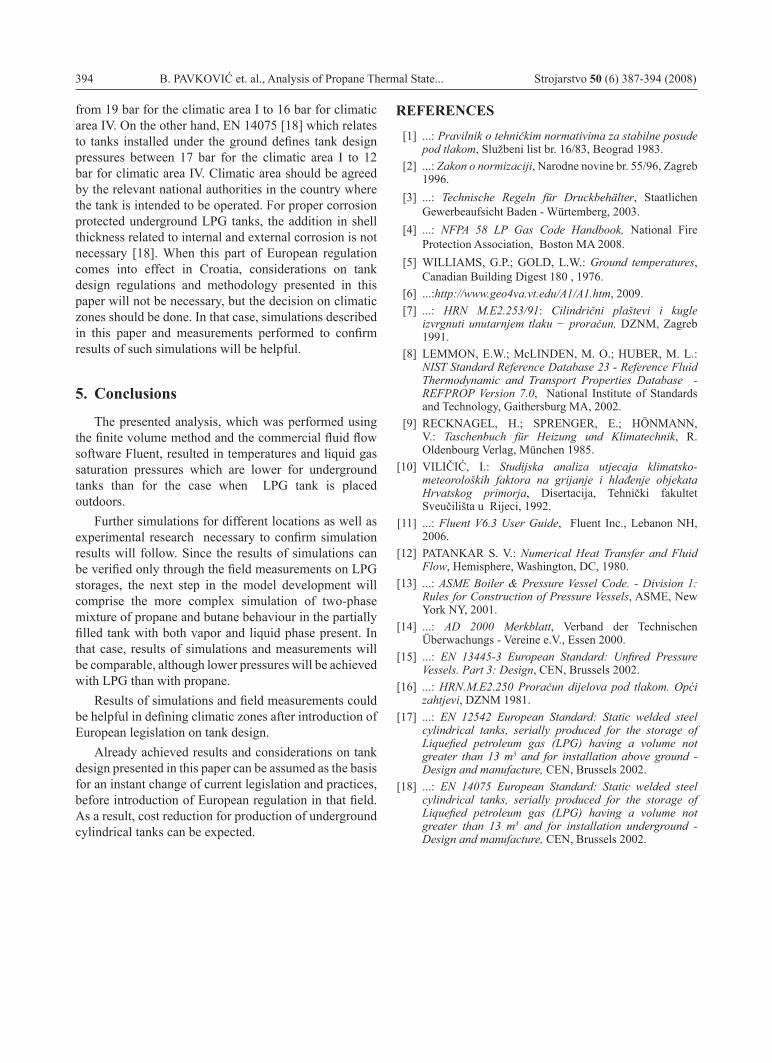
Tank temperatures and pressures are those which are interesting for the present analysis. Fast heat exchange occurs within the fluid in the tank and temperatures are almost uniform inside the tank. Those temperatures are presented in Figure 7 for internal and peripheral tank for depths of the cover soil layer 0,7 and 1,0 m respectively.
Figure 7. Changes of liquid propane temperature in the internal and peripheral tank for cover layer depths s = 0,7 and s = 1,0 m Slika 7. Promjene temperature kapljevitog propana u unutrašnjem i perifernom spremniku za dubine pokrovnog sloja s = 0,7 i s = 1,0 m
Increasing the depth of the soil layer above the tank affects the gas temperature by decreasing the highest and increasing the lowest saturated propane temperature. The temperature maximum for larger cover depths
occurs with a certain time delay compared to the smaller cover depths. The peripheral tank is, as it was expected, exposed to higher temperatures due to a larger surface being subject to external influences of solar radiation and external air temperature. The change of internal pressure presented in Figure 8 has been evaluated by using the saturation curve for propane, presented in Figure 2. It is obvious that the absolute pressure of 1,06 MPa (which means the design pressure 0,96 MPa) has not been exceeded. That means that the design pessure of 1,2 MPa is sufficient for the tank design for given boundary conditions. Similar simulations have been performed for meteorological data of the Split region as well as for the location Durres in Albania and in all cases similar results have been achieved leading to the conclusion that design pressure of 12 bar is sufficient.
4. Considerations on tank design and production
Depending on customers demands and inspectorate practice, stable pressure vessel in Croatia can be made by one among following standards: HRN M.E2.253 [7], ASME Section VIII [13], AD 2000 Merkblatt [14] or EN 13445-3 [15]. There are significant differences in approach to pressure vessel design among standards mentioned. Equations for evaluation of minimal wall thickness calculation according to standards mentioned are as follows:
Figure 6. Hourly values of soil temperatures at different depths for y = 0 mmSlika 6. Satne vrijednosti temperature tla na različitim dubinama za y = 0 mm
Strojarstvo 50 (6) 387-394 (2008) B. PAVKOVIĆ et. al., Analysis of Propane Thermal State... 393Analysis of Propane Thermal State... 393 393
Figure 8. Change of liquid propane pressure in the internal and peripheral tank for cover layer depths s = 0,7 and s = 1,0 m Slika 8. Promjene tlaka kapljevitog propana u unutrašnjem i perifernom spremniku za dubine pokrovnog sloja s = 0,7 i s = 1,0 m
According to HRN M.E2.253 group and AD Merkblatt rules wall thickness is evaluated as
,
(12)
where De [mm] is external diameter of cylindrical vessel, p [bar] design pressure at bottom of the vessel, K [N/mm2] design strength of wall material on design temperature, c1 [mm] addition to wall thickness due to tolerance in plate thicknes, c2 [mm] addition to wall thickness due to corrosion and wearing and w weld joint factor. As the approach to design by HRN M.E2.253 was assumed from AD Merkblatt rules, equation for the wall thickness is the same in both standards.
According to ASME VIII-Div. 1, in the case of longitudinal welds on cylindrical vessel wall thickness δ [mm] is
(13)
and in the case of circular welds on cylindrical vessel wall thickness δ is
,
(14)
where p [MPa] is internal design pressure, Ri [mm] internal vessel radius, Re [mm] external vessel radius w weld joint factor and K [MPa] allowed stress of wall material.
Minimal wall thickness for cylindrical pressure vessel is a higher value between two calculated by equations (13) and (14).
According to EN 13445-3, wall thickness of cylindrical shell of pressure vessel δ [mm] can be evaluated as:
(15)
or
,
(16)
where Di [mm] is internal vessel diameter, De [mm] external vessel diameter, w weld joint factor, K [MPa] design stress, and p [MPa] design pressure.
As an example of possible weight saving on pressure vessel, a calculation of minimal wall thickness of mounded cylindrical vessel is given. The volume of the vessel was 500 m3, and it was designed for LPG storage. Outer cylindrical shell diameter was De= 4 300 mm. Base material was weldable normalised fine grain steel P355NL1 (EN 10028/3) with design strength K= 355N/mm2. Weld joint factor was w = 1 and safety factor was S = 1,5. Maximum pressure was in the first case p= 1,64 MPa and p= 1,2 MPa in the second case. Design pressures have been increased for the additional static pressure of liquid propane, which was 0.02 MPa. Calculations were performed by standard HRN M.E2. 253 based on appropriate expression (12). The addition due to plate tolerance was c1=0 mm, and addition due to corrosion and wearing was c2=1 mm (additions are prescribed by standard HRN M.E2. 250 [16]).
Minimal wall thickness according to HRN M.E2.253 was 16.06 mm for design pressure of 1,66 MPa and 12,09 mm for design pressure 1,22 MPa. With assumed wall thicknesses of 17 mm for design pressure of 1,66 MPa calculated tank weight including all necessary equipment reach up to 77,141 kg. For design pressure 1,22 MPa the assumed wall thickness was 13 mm and calculated tank weight 63,205 kg. That means that the use of the design pressure 1,22 MPa could lead to approximate mass reduction of used steel of 18 %. As the internal pressure is not the only one cause of stresses in the tank, it is of course necessary to check those values for other forces that cause stress, such as external forces (for example, the weight of soil cover, lowest pressure etc.) and to choose the proper wall thickness and necessary elements for reinforcement of the tank.
Calculation according to EN 13445-3 results in lower wall thicknesses for both design pressures compared to calculation according to HRN M.E2.253. In the case of the calculation according to EN 13445-3, the wall thickness is 10.05 mm for design pressure of 1,66 MPa and 7,40 mm for design pressure 1,22 MPa. It should also be mentioned that European regulation already makes a distinction between tanks installed above the ground and underground tanks. EN 12542 [17] which relates to tanks installed above the ground defines tank design pressures which depend on the tank volume and climatic zones. For tanks with volume higher than 7 m3 design pressures differ
394 B. PAVKOVIĆ et. al., Analysis of Propane Thermal State... Strojarstvo 50 (6) 387-394 (2008)
from 19 bar for the climatic area I to 16 bar for climatic area IV. On the other hand, EN 14075 [18] which relates to tanks installed under the ground defines tank design pressures between 17 bar for the climatic area I to 12 bar for climatic area IV. Climatic area should be agreed by the relevant national authorities in the country where the tank is intended to be operated. For proper corrosion protected underground LPG tanks, the addition in shell thickness related to internal and external corrosion is not necessary [18]. When this part of European regulation comes into effect in Croatia, considerations on tank design regulations and methodology presented in this paper will not be necessary, but the decision on climatic zones should be done. In that case, simulations described in this paper and measurements performed to confirm results of such simulations will be helpful.
5. Conclusions
The presented analysis, which was performed using the finite volume method and the commercial fluid flow software Fluent, resulted in temperatures and liquid gas saturation pressures which are lower for underground tanks than for the case when LPG tank is placed outdoors.
Further simulations for different locations as well as experimental research necessary to confirm simulation results will follow. Since the results of simulations can be verified only through the field measurements on LPG storages, the next step in the model development will comprise the more complex simulation of two-phase mixture of propane and butane behaviour in the partially filled tank with both vapor and liquid phase present. In that case, results of simulations and measurements will be comparable, although lower pressures will be achieved with LPG than with propane.
Results of simulations and field measurements could be helpful in defining climatic zones after introduction of European legislation on tank design.
Already achieved results and considerations on tank design presented in this paper can be assumed as the basis for an instant change of current legislation and practices, before introduction of European regulation in that field. As a result, cost reduction for production of underground cylindrical tanks can be expected.
REFERENCES
[1] ...: Pravilnik o tehničkim normativima za stabilne posude pod tlakom, Službeni list br. 16/83, Beograd 1983.
[2] ...: Zakon o normizaciji, Narodne novine br. 55/96, Zagreb 1996.
[3] ...: Technische Regeln für Druckbehälter, Staatlichen Gewerbeaufsicht Baden - Würtemberg, 2003.
[4] ...: NFPA 58 LP Gas Code Handbook, National Fire Protection Association, Boston MA 2008.
[5] WILLIAMS, G.P.; GOLD, L.W.: Ground temperatures, Canadian Building Digest 180 , 1976.
[6] ...:http://www.geo4va.vt.edu/A1/A1.htm, 2009. [7] ...: HRN M.E2.253/91: Cilindrični plaštevi i kugle
izvrgnuti unutarnjem tlaku − proračun, DZNM, Zagreb 1991.
[8] LEMMON, E.W.; McLINDEN, M. O.; HUBER, M. L.: NIST Standard Reference Database 23 - Reference Fluid Thermodynamic and Transport Properties Database - REFPROP Version 7.0, National Institute of Standards and Technology, Gaithersburg MA, 2002.
[9] RECKNAGEL, H.; SPRENGER, E.; HÖNMANN, V.: Taschenbuch für Heizung und Klimatechnik, R. Oldenbourg Verlag, München 1985.
[10] VILIČIĆ, I.: Studijska analiza utjecaja klimatsko-meteoroloških faktora na grijanje i hlađenje objekata Hrvatskog primorja, Disertacija, Tehnički fakultet Sveučilišta u Rijeci, 1992.
[11] ...: Fluent V6.3 User Guide, Fluent Inc., Lebanon NH, 2006.
[12] PATANKAR S. V.: Numerical Heat Transfer and Fluid Flow, Hemisphere, Washington, DC, 1980.
[13] ...: ASME Boiler & Pressure Vessel Code. - Division 1: Rules for Construction of Pressure Vessels, ASME, New York NY, 2001.
[14] ...: AD 2000 Merkblatt, Verband der Technischen Überwachungs - Vereine e.V., Essen 2000.
[15] ...: EN 13445-3 European Standard: Unfired Pressure Vessels. Part 3: Design, CEN, Brussels 2002.
[16] ...: HRN.M.E2.250 Proračun dijelova pod tlakom. Opći zahtjevi, DZNM 1981.
[17] ...: EN 12542 European Standard: Static welded steel cylindrical tanks, serially produced for the storage of Liquefied petroleum gas (LPG) having a volume not greater than 13 m3 and for installation above ground - Design and manufacture, CEN, Brussels 2002.
[18] ...: EN 14075 European Standard: Static welded steel cylindrical tanks, serially produced for the storage of Liquefied petroleum gas (LPG) having a volume not greater than 13 m3 and for installation underground - Design and manufacture, CEN, Brussels 2002.