Embed Size (px)
Citation preview

1
Analysis of Resonant-CavityLight-Emitting Diodes
Analysis of Resonant-CavityLight-Emitting Diodes
Copyright 2006 Crosslight Software Inc.www.crosslight.com

2
Contents Contents Contents
n About RCLED.n Crosslight’s model.n Example of an InGaAs/AlGaAs RCLED
with experimental verification.n Example of a VCSEL-like RCLED of
GaAs/AlGaAs MQW.n RCLED with detuned DBR.n RCLED with long cavity.n Conclusions.
n About RCLED.n Crosslight’s model.n Example of an InGaAs/AlGaAs RCLED
with experimental verification.n Example of a VCSEL-like RCLED of
GaAs/AlGaAs MQW.n RCLED with detuned DBR.n RCLED with long cavity.n Conclusions.
3
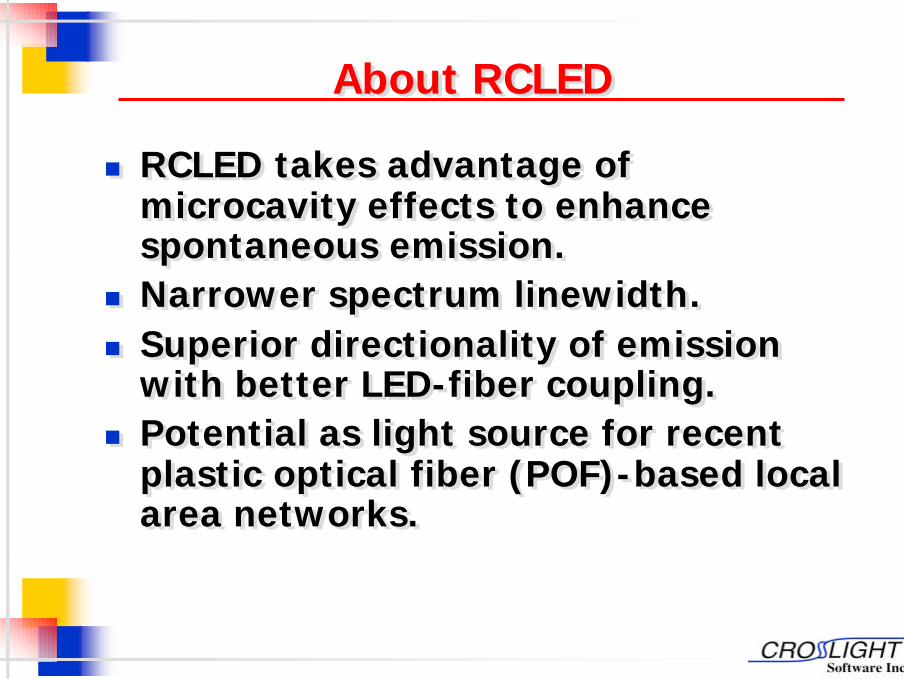
About RCLED About RCLED About RCLED
n RCLED takes advantage of microcavity effects to enhance spontaneous emission.
n Narrower spectrum linewidth.n Superior directionality of emission
with better LED-fiber coupling.n Potential as light source for recent
plastic optical fiber (POF)-based local area networks.
n RCLED takes advantage of microcavity effects to enhance spontaneous emission.
n Narrower spectrum linewidth.n Superior directionality of emission
with better LED-fiber coupling.n Potential as light source for recent
plastic optical fiber (POF)-based local area networks.

4
Crosslight RCLED modelCrosslight Crosslight RCLED modelRCLED modeln Self-consistent calculation of material spontaneous
emission rate based on rigorous quantum well/dot spectrum theories coupled with 2/3D simulation of current injection from the Crosslight APSYS drift-diffusion solver.
n Coupling of spontaneous emission with microcavity modes based on theory of C. H. Henry (1986) [1].
n Henry’s theory has been extended from waveguide to RCLED by proper accounting of mode densities in a quasi-2D/3D emission situation.
n Photon recycling effects taken into account by accurate determination of photon power density inside the RCLED and self-consistent model of material gain/loss of the quantum wells/dots.
n Self-consistent calculation of material spontaneous emission rate based on rigorous quantum well/dot spectrum theories coupled with 2/3D simulation of current injection from the Crosslight APSYS drift-diffusion solver.
n Coupling of spontaneous emission with microcavity modes based on theory of C. H. Henry (1986) [1].
n Henry’s theory has been extended from waveguide to RCLED by proper accounting of mode densities in a quasi-2D/3D emission situation.
n Photon recycling effects taken into account by accurate determination of photon power density inside the RCLED and self-consistent model of material gain/loss of the quantum wells/dots.
[1] C. H. Henry, "Theory of spontaneous emission noise
in open resonators and its application to lasers and optical amplifiers,"
J. Lightwave Technol., vol. LT-4, pp. 288--297, March 1986.

5
Contents Contents Contents
n About RCLED.n Crosslight’s model.n Example of an InGaAs/AlGaAs RCLED
with experimental verification.n Example of a VCSEL-like RCLED of
GaAs/AlGaAs MQW.n RCLED with detuned DBR.n RCLED with long cavity.n Conclusions.
n About RCLED.n Crosslight’s model.n Example of an InGaAs/AlGaAs RCLED
with experimental verification.n Example of a VCSEL-like RCLED of
GaAs/AlGaAs MQW.n RCLED with detuned DBR.n RCLED with long cavity.n Conclusions.
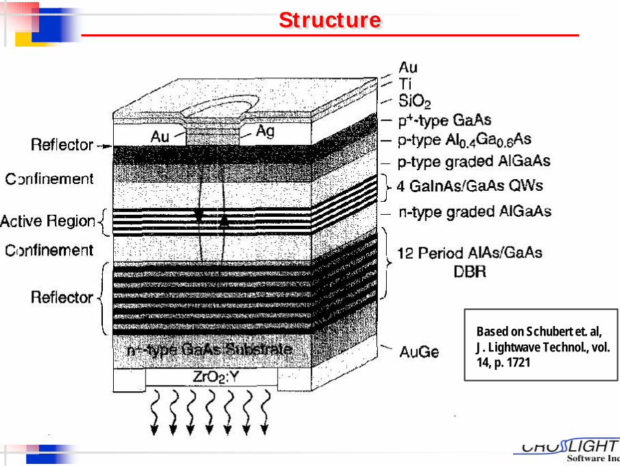
6Structure Structure Structure
Based on Schubert et. al, J. Lightwave Technol., vol. 14, p. 1721
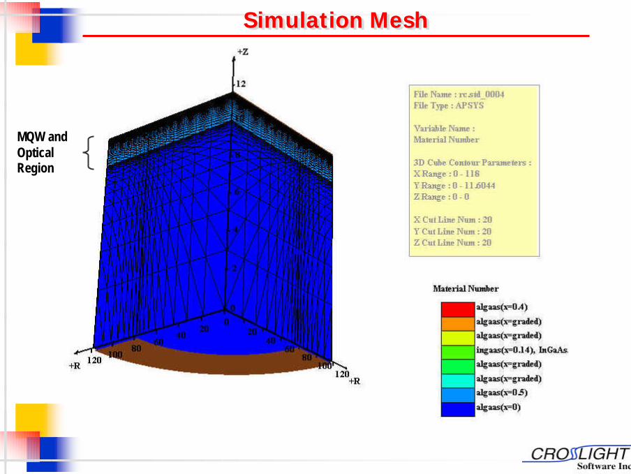
7Simulation MeshSimulation MeshSimulation Mesh
MQW and Optical Region

82/3D Drift-Diffusion Model2/3D Drift2/3D Drift--Diffusion ModelDiffusion Model
3D Potential distribution
Distribution of y-component of electronic current
DBR Region
MQW Region
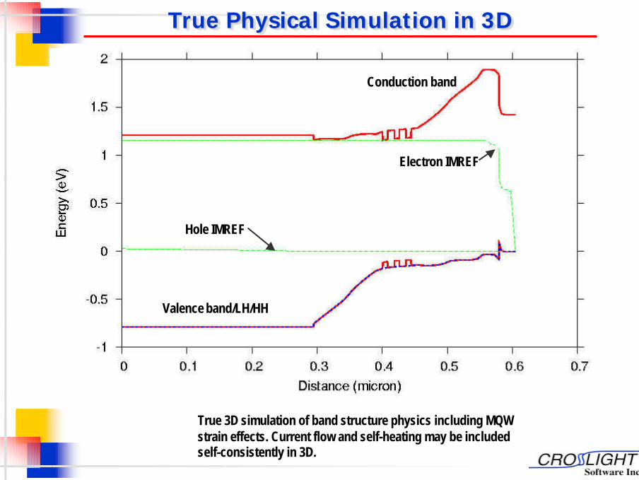
9True Physical Simulation in 3DTrue Physical Simulation in 3DTrue Physical Simulation in 3D
Electron IMREF
Hole IMREF
Valence band/LH/HH
Conduction band
True 3D simulation of band structure physics including MQW strain effects. Current flow and self-heating may be included self-consistently in 3D.
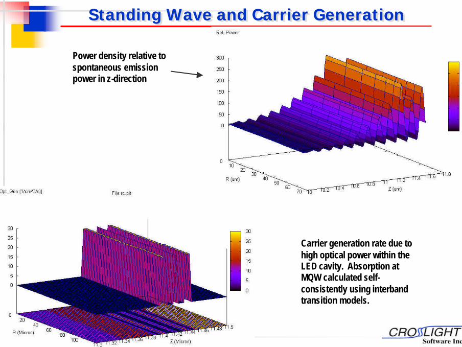
10Standing Wave and Carrier GenerationStanding Wave and Carrier GenerationStanding Wave and Carrier Generation
Power density relative to spontaneous emission power in z-direction
Carrier generation rate due to high optical power within the LED cavity. Absorption at MQW calculated self-consistently using interband transition models.

11Standing Wave and IndexStanding Wave and IndexStanding Wave and Index
Remark: The reflection phase of the Ag. Mirror is adjusted so that antinode of standing wave aligns with the MQW region.
Re-scaled power density
Refractive index
MQW

12Photon Recycling and IQEPhoton Recycling and IQEPhoton Recycling and IQE
n High mirror reflectivity è higher photon density in cavity under resonant condition.
n Re-absorbed photons è higher photo carrier densities (self-photo-pumping).
n Higher carrier concentration èmore photon emission by spontaneous emission (enhanced by microcavity resonance).
n Actual spontaneous emission rate substantially higher than current injection rate.
n IQE calculation = spontaneous emission rate subtracting photon absorption rate, dividing current injection rate.
Spont.Em.
Re-Absorp.
Self-pumping

13Improvement in Spectrum LinewidthImprovement in Spectrum Improvement in Spectrum LinewidthLinewidth
ExperimentalData taken from Schubert et. al, J. Lightwave Technol., vol. 14, p. 1721
MQW material emission without RC effects
4 curves from 2.5 to 10 mA injection
Simulated EL emission from bottom facet of RCLED.
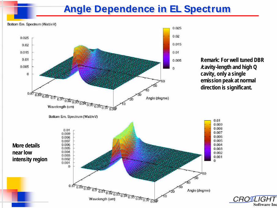
14Angle Dependence in EL SpectrumAngle Dependence in EL SpectrumAngle Dependence in EL Spectrum
Remark: For well tuned DBR /cavity-length and high Q cavity, only a single emission peak at normal direction is significant.
More details near low intensity region

15
Contents Contents Contents
n About RCLED.n Crosslight’s model.n Example of an InGaAs/AlGaAs RCLED
with experimental verification.n Example of a VCSEL-like RCLED of
GaAs/AlGaAs MQW.n RCLED with detuned DBR.n RCLED with long cavity.n Conclusions.
n About RCLED.n Crosslight’s model.n Example of an InGaAs/AlGaAs RCLED
with experimental verification.n Example of a VCSEL-like RCLED of
GaAs/AlGaAs MQW.n RCLED with detuned DBR.n RCLED with long cavity.n Conclusions.

16Structure of AlGaAs RCLEDStructure of Structure of AlGaAs AlGaAs RCLEDRCLED
A VCSEL-like structure with fewer layer pairs in top DBR to help power extraction. Ion implantation is used to form current confinement.
MQW
Implanted current confinement region
Top DBR
Bottom DBR

172/3 Dim Drift-Diffusion Model2/3 Dim Drift2/3 Dim Drift--Diffusion ModelDiffusion Model
Y-component of electron current distribution in RCLED. Please note the strong (blue) current crowding area which causes optical gain to help amplify the optical waves there.
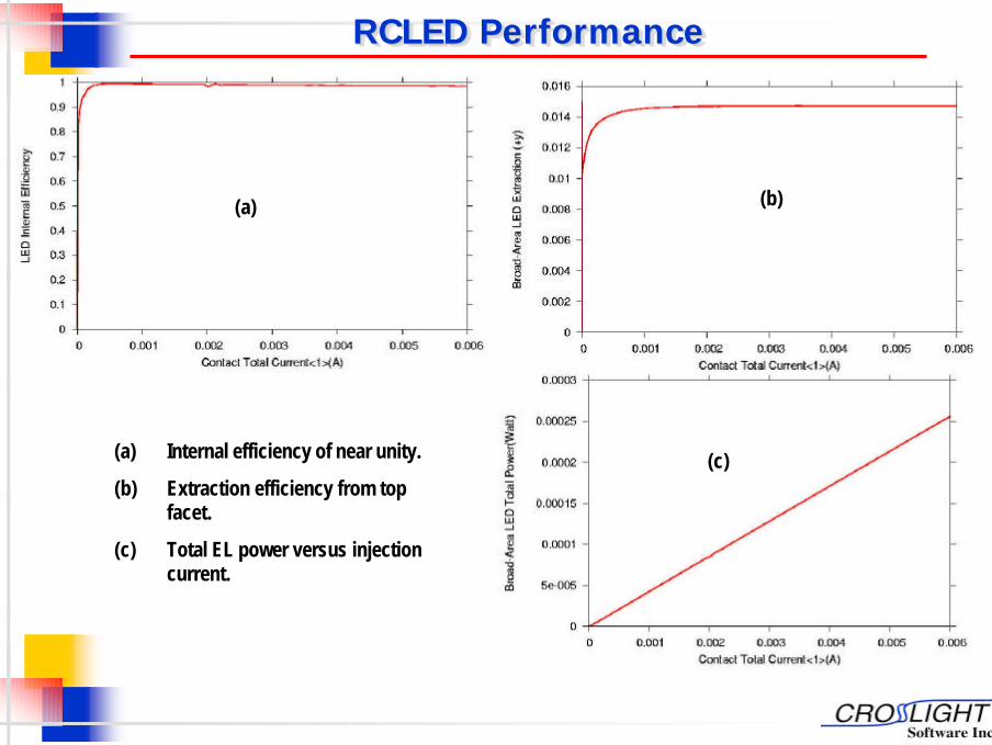
18RCLED PerformanceRCLED PerformanceRCLED Performance
(a) Internal efficiency of near unity.
(b) Extraction efficiency from top facet.
(c) Total EL power versus injection current.
(a) (b)
(c)

19Current Crowding EffectsCurrent Crowding EffectsCurrent Crowding Effects
MQW spontaneous emission distribution under top aperture. Lateral distribution is due to current crowding.
Standing wave shows strong lateral variation due to gain/’spontaneous emission rate distribution.

20Standing Wave AlignmentStanding Wave AlignmentStanding Wave Alignment
Remark: Effective cavity length near the MQW should be (n+1/2) wavelength to ensure antinode of standing wave aligns with MQW.
Scaled power
Index profile MQW
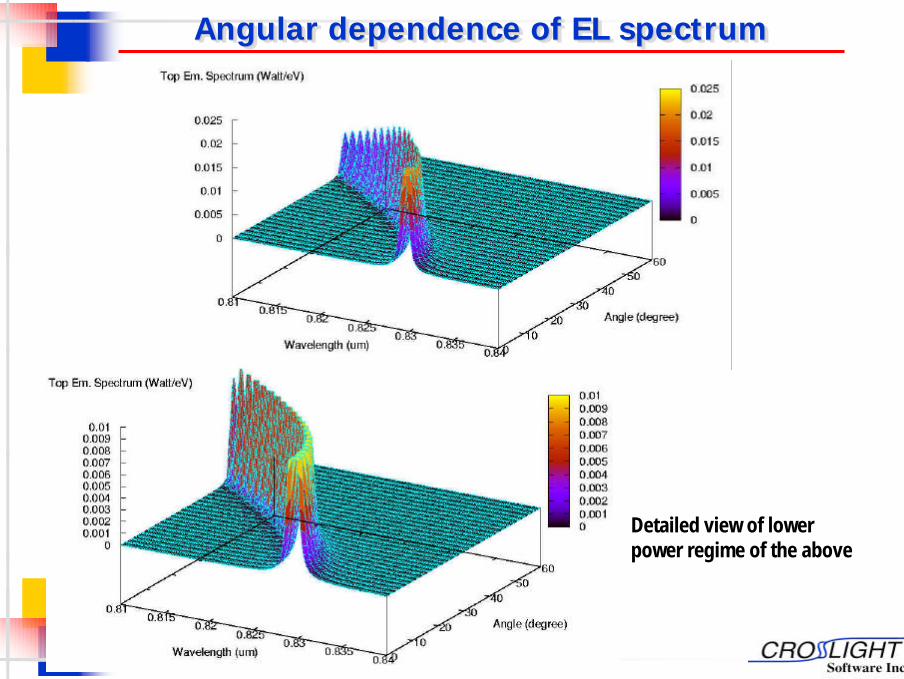
21Angular dependence of EL spectrumAngular dependence of EL spectrumAngular dependence of EL spectrum
Detailed view of lower power regime of the above

22
Contents Contents Contents
n About RCLED.n Crosslight’s model.n Example of an InGaAs/AlGaAs RCLED
with experimental verification.n Example of a VCSEL-like RCLED of
GaAs/AlGaAs MQW.n RCLED with detuned DBR.n RCLED with long cavity.n Conclusions.
n About RCLED.n Crosslight’s model.n Example of an InGaAs/AlGaAs RCLED
with experimental verification.n Example of a VCSEL-like RCLED of
GaAs/AlGaAs MQW.n RCLED with detuned DBR.n RCLED with long cavity.n Conclusions.
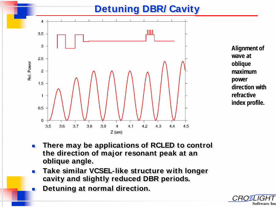
23Detuning DBR/Cavity Detuning DBR/Cavity Detuning DBR/Cavity
n There may be applications of RCLED to control the direction of major resonant peak at an oblique angle.
n Take similar VCSEL-like structure with longer cavity and slightly reduced DBR periods.
n Detuning at normal direction.
n There may be applications of RCLED to control the direction of major resonant peak at an oblique angle.
n Take similar VCSEL-like structure with longer cavity and slightly reduced DBR periods.
n Detuning at normal direction.
Alignment of wave at oblique maximum power direction with refractive index profile.
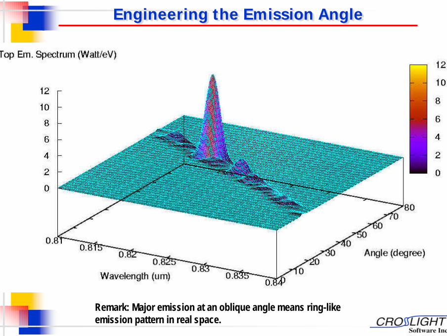
24Engineering the Emission AngleEngineering the Emission AngleEngineering the Emission Angle
Remark: Major emission at an oblique angle means ring-like emission pattern in real space.
25
Contents Contents Contents
n About RCLED.n Crosslight’s model.n Example of an InGaAs/AlGaAs RCLED
with experimental verification.n Example of a VCSEL-like RCLED of
GaAs/AlGaAs MQW.n RCLED with detuned DBR.n RCLED with long cavity.n Conclusions.
n About RCLED.n Crosslight’s model.n Example of an InGaAs/AlGaAs RCLED
with experimental verification.n Example of a VCSEL-like RCLED of
GaAs/AlGaAs MQW.n RCLED with detuned DBR.n RCLED with long cavity.n Conclusions.
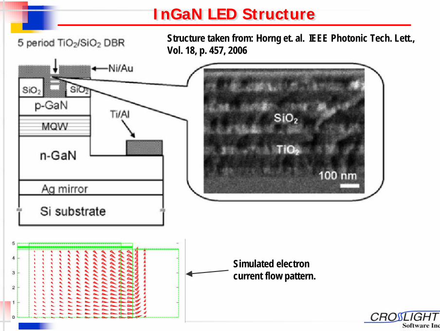
26InGaN LED Structure InGaNInGaN LED Structure LED Structure
Structure taken from: Horng et. al. IEEE Photonic Tech. Lett., Vol. 18, p. 457, 2006
Simulated electron current flow pattern.
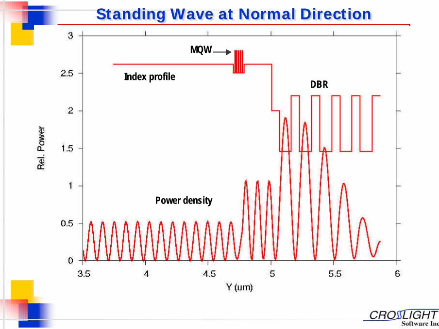
27Standing Wave at Normal DirectionStanding Wave at Normal DirectionStanding Wave at Normal Direction
DBR
MQW
Index profile
Power density

28Multiple Resonance Peaks as Compared with ExperimentMultiple Resonance Peaks as Compared with ExperimentMultiple Resonance Peaks as Compared with Experiment

29
ConclusionsConclusionsConclusions
n A comprehensive physical model of resonant cavity has been incorporated into Crosslight’s APSYS/LED modules.
n Based on rigorous theory describing interaction of spontaneous emission spectrum with microcavity modes.
n Resonant effects in spatial, spectral and angular dimensions have been obtained in reasonable agreement with experiments.
n Self-consistent integration with the main APSYS simulator enables all-in-one analysis and design approach.