Embed Size (px)
Citation preview
NASA Technical Memorandum 110170
j ,i f ""
3K
Analysis of Selected CompressionSplice Joint Locations in a Graphite-Epoxy Transport Wing Stub Box
D. C. Jegley
Langley Research Center, Hampton, Virginia
0 _NN_0
I,0
Z
u_m
U
O
_O
00OO
0"
October 1995
National Aeronauticsand
Space AdministrationLangley Research CenterHampton, Virginia 23681-0001
Z
ku OZ rq
)- !_- w ><
ZZ_ C_ 0 a. co O)
OUJ U
_. Z_O_Z_
I I,-- _-'_ I_.
Z u3 0 o_ m
https://ntrs.nasa.gov/search.jsp?R=19960009063 2020-07-28T17:20:22+00:00Z


ANALYSIS OF SELECTED COMPRESSION SPLICE JOINT LOCATIONS IN
A GRAPHITE-EPOXY TRANSPORT WING STUB BOX
Abstract
Three critical compression splice joint locations in a stitched graphite-epoxy
transport wing stub box have been analyzed to determine their expected
structural performance. The wing box is representative of a section of a
commercial transport wing box and was designed and constructed by
McDonnell Douglas Aerospace Company as part of the NASA Advanced
Composites Technology (ACT) program. The results of the finite element
analyses of the splice joints are presented. The analysis results indicate that
failure will not occur in the splice joint regions for loads less than the Design
Ultimate Load of the wing box.
Introduction
To evaluate the potential of a stitched graphite-epoxy material form for use on
commercial transport aircraft wings, a short section of a wing box was
designed and fabricated by the McDonnell Douglas Aerospace Company under
the NASA Advanced Composites Technology Program (ACT) contract NAS1-
18862. This short wing-box section is referred to herein as the "wing stub
box." Current plans are to test the wing stub box at the NASA Langley
Research Center to evaluate its structural performance. Several structural
analyses were conducted by McDonnell Douglas Aerospace Company and by
NASA Langley Research Center in support of this effort. The present paper
describes the results of the analysis of three compression-loaded splice
locations in the wing-stub-box test specimen.
Wing-Stub-Box Test-Specimen Description
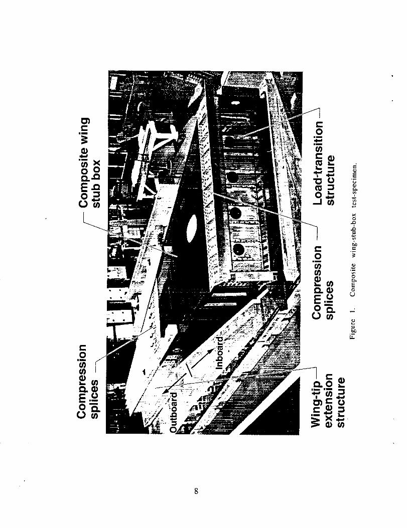
The wing-stub-box structure consists of a metallic load-transition structure at
the wing root, a composite wing stub box, and a metallic extension structure at
the wing tip as shown in figure 1. The load-transition structure and the wing-
tip extension structure are metallic end fixtures required for appropriate load
introduction into the composite wing stub box during the test. The load-
transition structure is located inboard of the composite wing stub box
(between the composite wing stub box and the vertical reaction structure at
the wing-stub-box root) and the wing-tip extension structure is located
outboard of the composite wing stub box. The load-transition structure is
mounted to a steel and concrete vertical reaction structure resulting in a near-
clamped end condition. The entire structure, including the composite wing
stub box and the metallic structures, is approximately 25 feet long. Details of
the geometry of the structure are presented in reference 1.
The composite wing stub box was fabricated from Hercules, Inc. AS4/3501-6
and IM7/3501-6 graphite-epoxy materials which are stitched together using E.
I. DuPont de Nemours Inc. Kevlar threads. IM7 graphite fibers are only used
for the 0 degree fibers in the lower skin. The composite skin and stiffeners
are composed of layers of the graphite material forms prekitted in nine-ply
stacks that have a [45/-45/02/90102/-45/45]T stacking sequence. Each nine-
ply stack is approximately .058 inches thick. Several nine-ply stacks of the
prekitted material are used to build up the desired thickness at each location.
The composite wing stub box was fabricated using a Resin Film Infusion (RFI)
process (see ref. 2).
Splice Description
Metallic splices are used to join the composite wing stub box to the metallic
wing-tip extension structure and to the metallic toad-transition structure (as
indicated in figure 1). These metallic splices are bolted to the ends of the
graphite-epoxy stiffeners and to the metallic extension and load-transition
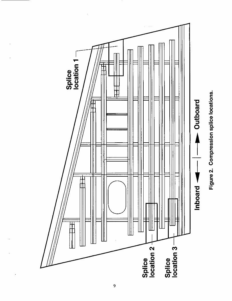
structures. Three splice locations on the upper cover panel of the composite
wing stub box have been analyzed in detail and the results of the analysis of
the three splices are presented in the present paper. The locations of the
three splicesare shownin figure 2. Splice 1 is locatedat the outboardend of
the compositewing stub box. Splices2 and 3 are locatedat the inboardend ofthe compositewing stub box.
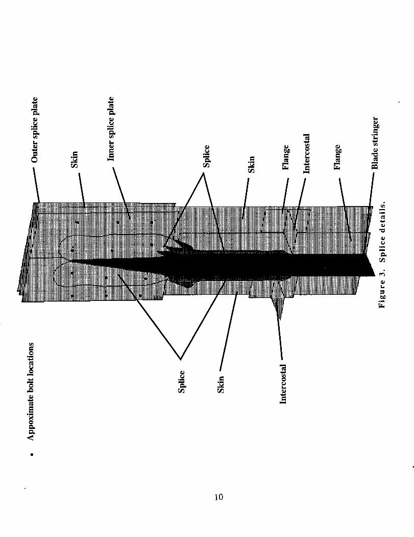
Each splice consistsof aluminum inner and outer splice plates and aluminumangle splices,as shownin figure 3. Bolts are usedto attachthe stiffener to the
angle splices and the skin to the inner and outer splice plates. All stiffeners
are approximately2.3 inches high and .46 inches thick with a 1.12-inch-wide
flange on either side of the blade. The distancebetweenthe end of the
composite upper-cover-panelskin and the end of the compositestringer is8.59 inches(as shownin figure 2) for all splicesconsidered. However, thedistancebetween the end of the compositestringer and the nearestrib is
different for the three splicesconsidered. The distancesfor splice locations 1,2, and 3 are shownin figure 2 and are 6.1 inches,6.4 inchesand 2.8 inches,
respectively.
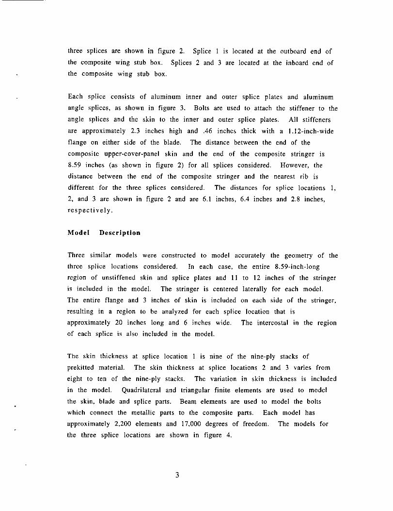
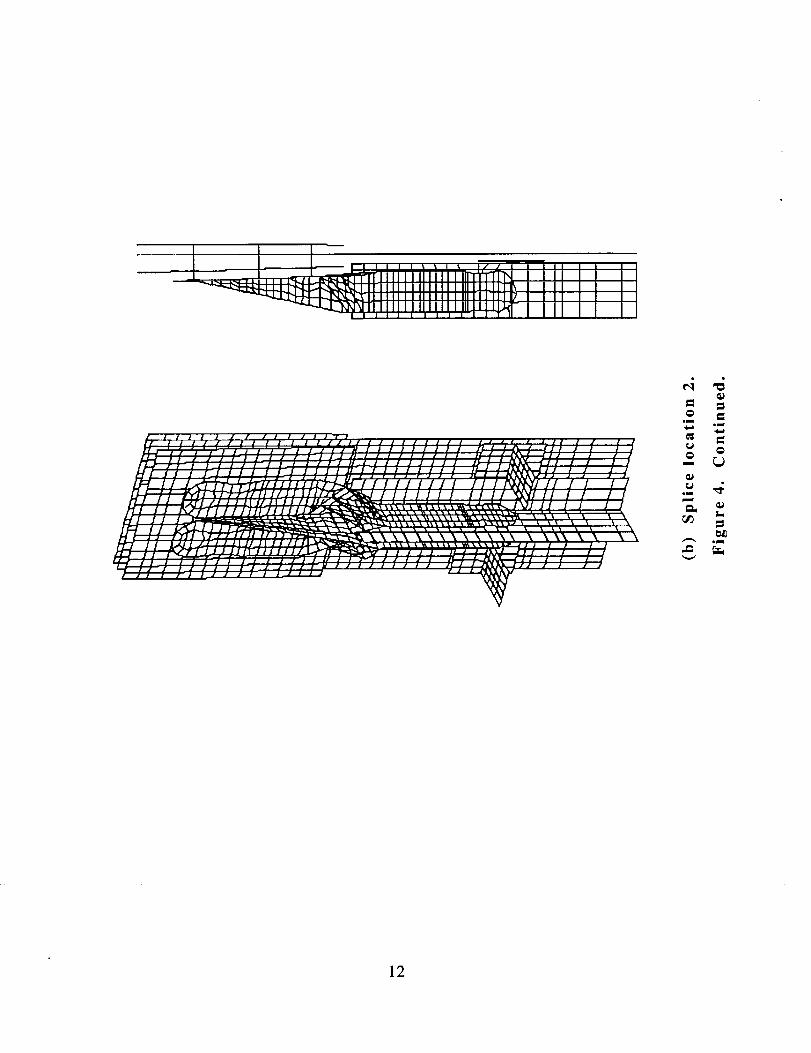
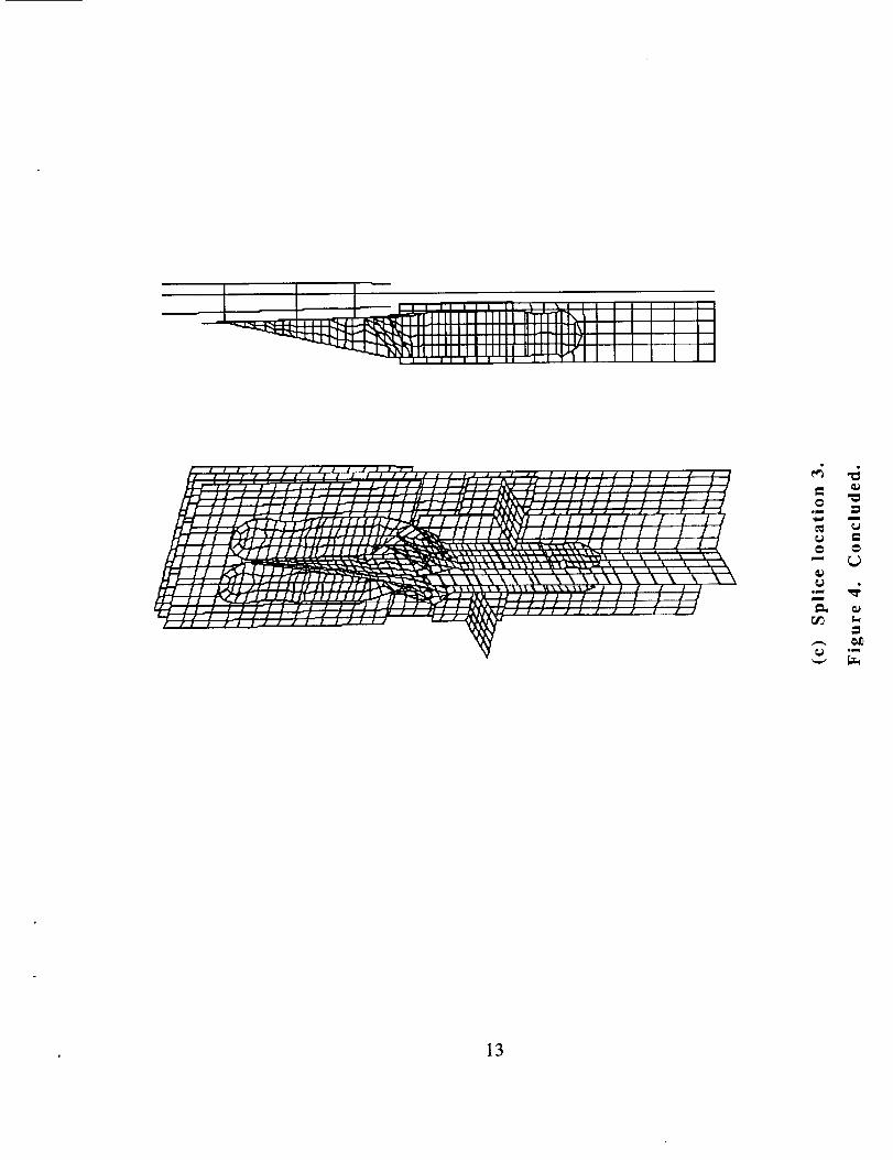
Model Description
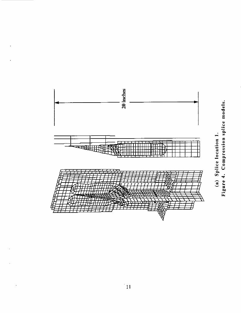
Three similar models were constructed to model accurately the geometry of the
three splice locations considered. In each case, the entire 8.59-inch-long
region of unstiffened skin and splice plates and 11 to 12 inches of the stringer
is included in the model. The stringer is centered laterally for each model.
The entire flange and 3 inches of skin is included on each side of the stringer,
resulting in a region to be analyzed for each splice location that is
approximately 20 inches long and 6 inches wide. The intercostal in the region
of each splice is also included in the model.
The skin thickness at splice location 1 is nine of the nine-ply stacks of
prekitted material. The skin thickness at splice locations 2 and 3 varies from
eight to ten of the nine-ply stacks. The variation in skin thickness is included
in the model. Quadrilateral and triangular finite elements are used to model
the skin, blade and splice parts. Beam elements are used to model the bolts
which connect the metallic parts to the composite parts. Each model has
approximately 2,200 elements and 17,000 degrees of freedom. The models for
the three splice locations are shown in figure 4.
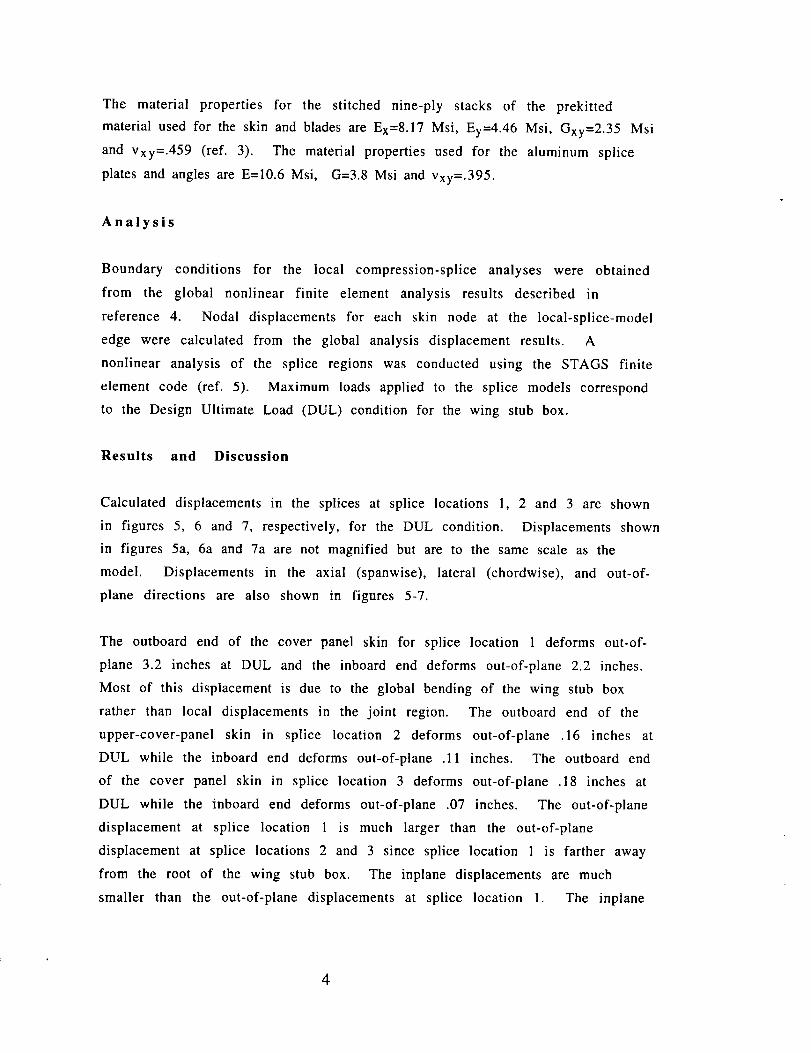
The material properties for the stitched nine-ply stacks of the prekitted
materialusedfor the skin andbladesareEx=8.17Msi, Ey=4.46Msi, Gxy=2.35Msiand Vxy=.459 (ref. 3). The materialpropertiesused for the aluminumsplice
platesandanglesareE=10.6Msi, G=3.8Msi andVxy=.395.
Analysis
Boundary conditions for the local compression-splice analyses were obtained
from the global nonlinear finite element analysis results described in
reference 4. Nodal displacements for each skin node at the local-splice-model
edge were calculated from the global analysis displacement results. A
nonlinear analysis of the splice regions was conducted using the STAGS finite
element code (ref. 5). Maximum loads applied to the splice models correspond
to the Design Ultimate Load (DUL) condition for the wing stub box.
Results and Discussion
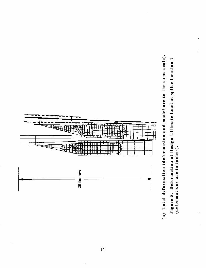
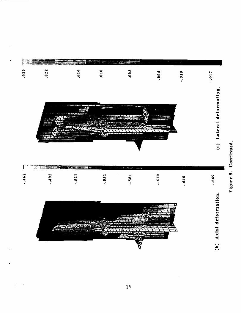
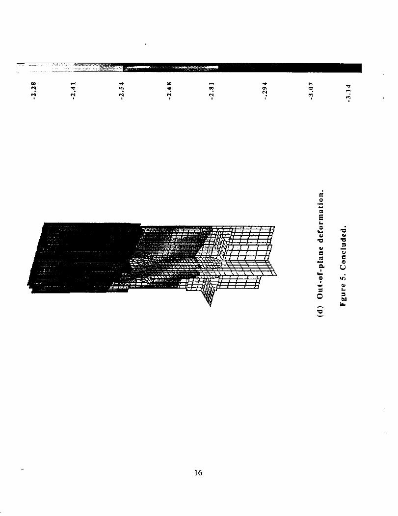
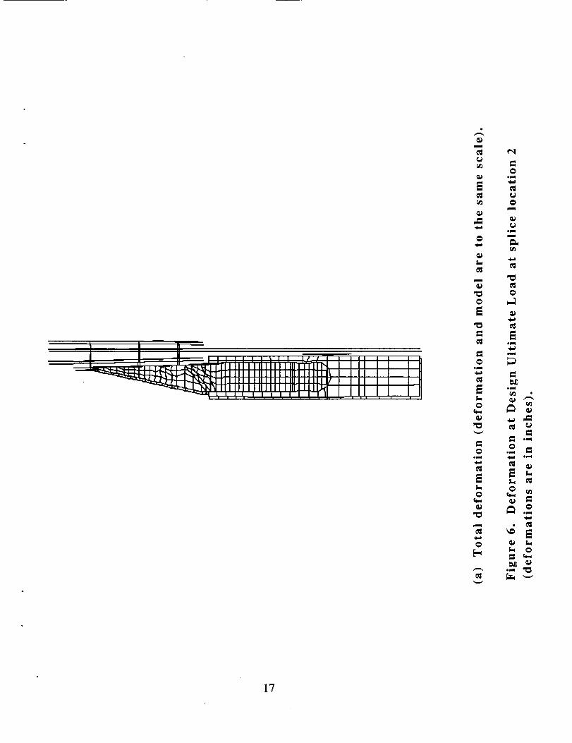
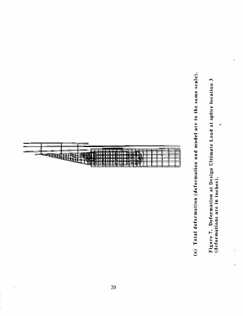
Calculated displacements in the splices at splice locations 1, 2 and 3 are shown
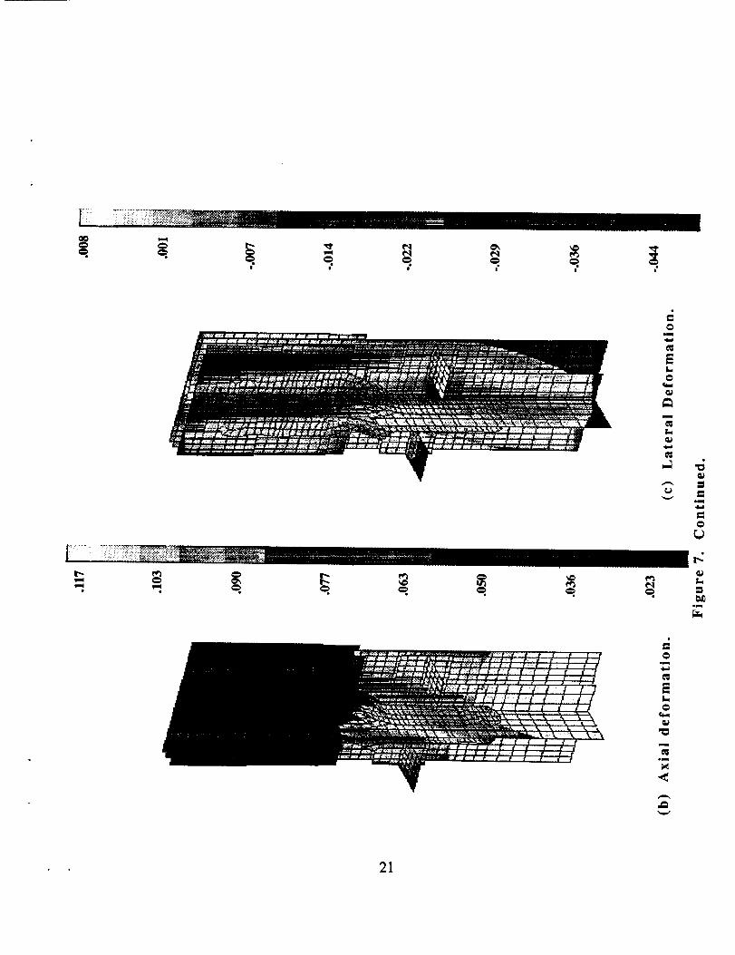
in figures 5, 6 and 7, respectively, for the DUL condition. Displacements shown
in figures 5a, 6a and 7a are not magnified but are to the same scale as the
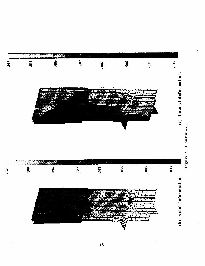
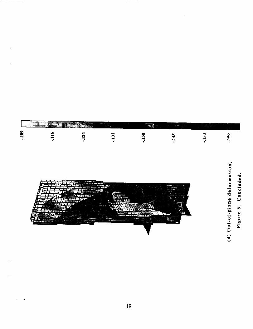
model. Displacements in the axial (spanwise), lateral (chordwise), and out-of-
plane directions are also shown in figures 5-7.
The outboard end of the cover panel skin for splice location 1 deforms out-of-
plane 3.2 inches at DUL and the inboard end deforms out-of-plane 2.2 inches.
Most of this displacement is due to the global bending of the wing stub box
rather than local displacements in the joint region. The outboard end of the
upper-cover-panel skin in splice location 2 deforms out-of-plane .16 inches at
DUL while the inboard end deforms out-of-plane .11 inches. The outboard end
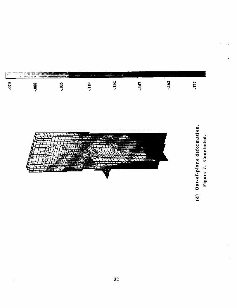
of the cover panel skin in splice location 3 deforms out-of-plane .18 inches at
DUL while the inboard end deforms out-of-plane .07 inches. The out-of-plane
displacement at splice location 1 is much larger than the out-of-plane
displacement at splice locations 2 and 3 since splice location 1 is farther away
from the root of the wing stub box. The inplane displacements are much
smaller than the out-of-plane displacements at splice location 1. The inplane
4
displacementsare of the sameorder of magnitudeas the out-of-planedisplacementsat splice locations2 and 3.
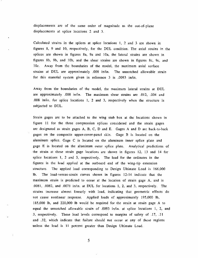
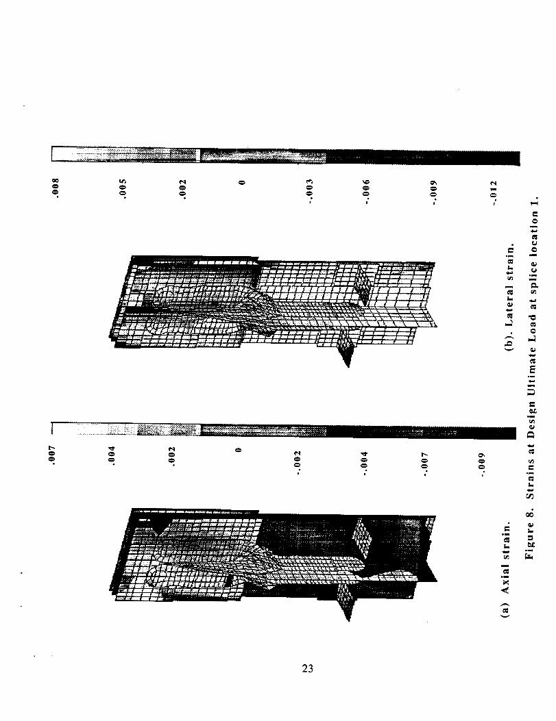
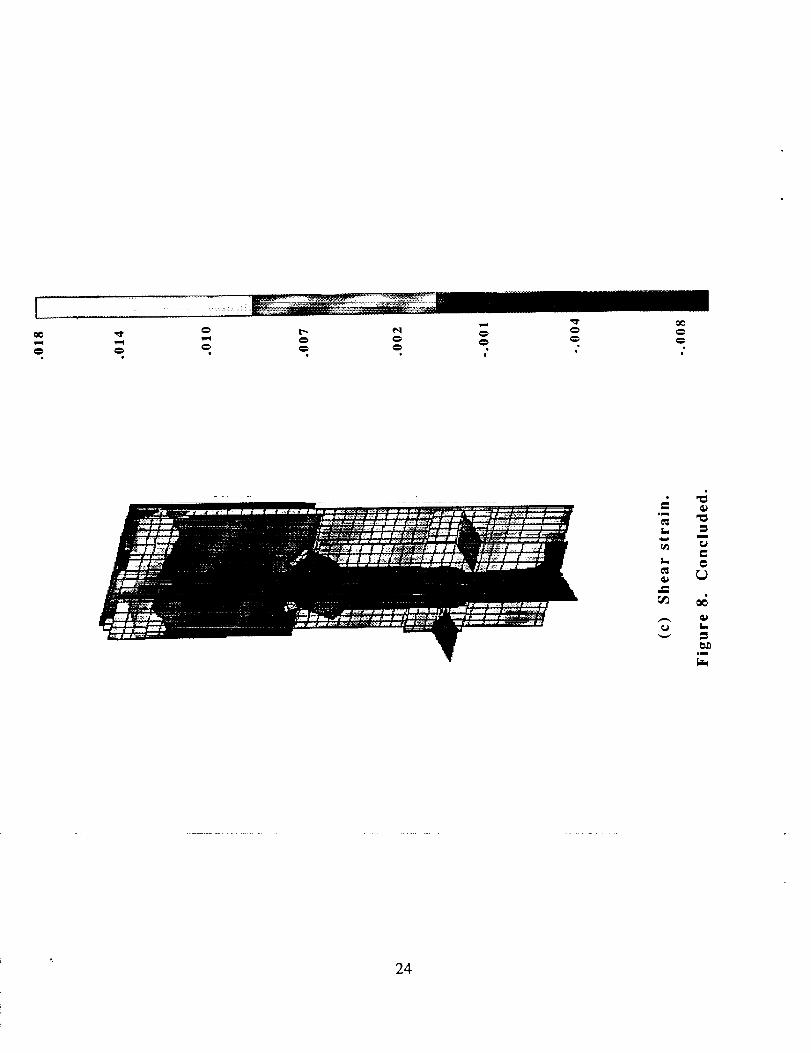
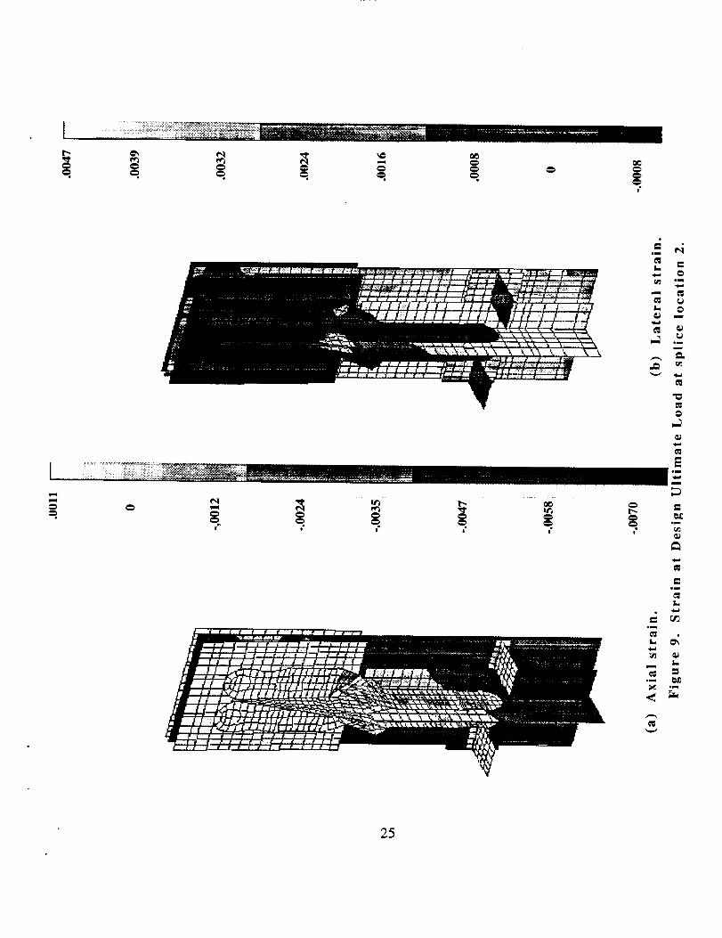
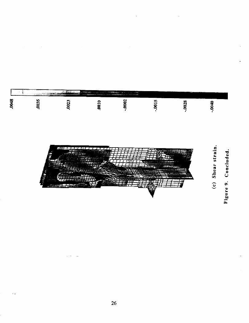
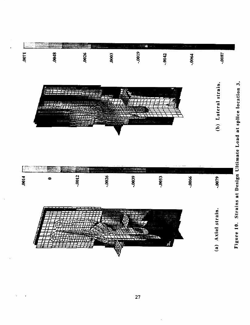
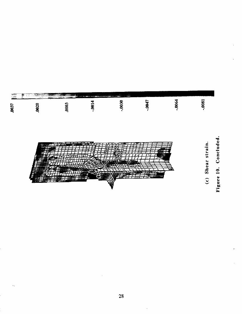
Calculatedstrains in the splicesat splice locations1, 2 and 3 are shown in
figures 8, 9 and 10, respectively,for the DUL condition.The axial strains in thesplices are shownin figures 8a, 9a and 10a, the lateral strains are shown in
figures 8b, 9b, and 10b, and the shearstrainsare shownin figures 8c, 9c, and10c. Away from the boundariesof the model, the maximumaxial surface
strains at DUL are approximately.008 in/in. The unnotchedallowable strain
for this material systemgiven in reference3 is .0093 in/in.
Away from the boundariesof the model, the maximumlateral strainsat DUL
are approximately.008 in/in. The maximum shear strains are .012, .004 and
.008 in/in, for splice locations 1, 2 and 3, respectively when the structure is
subjected to DUL.
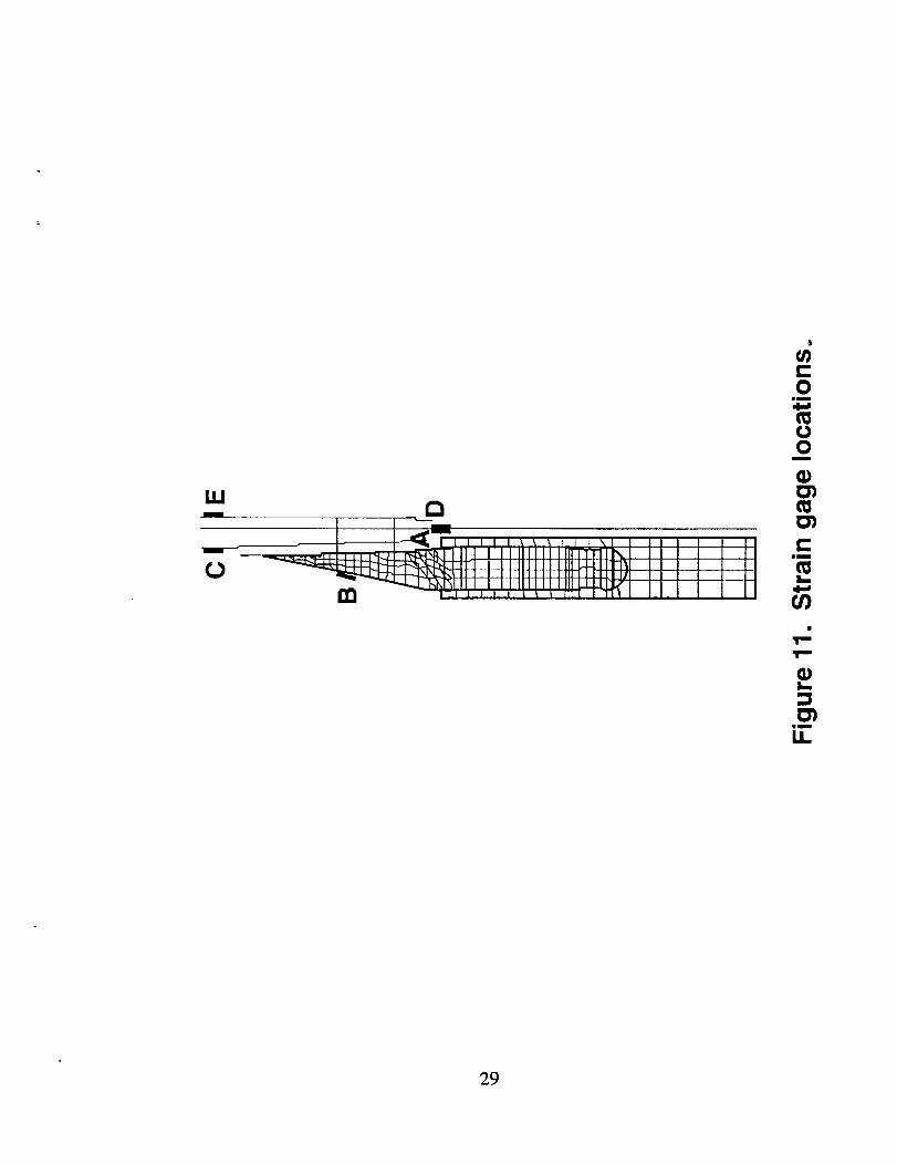
Strain gages are to be attached to the wing stub box at the locations shown in
figure 11 for the three compression splices considered and the strain gages
are designated as strain gages A, B, C, D and E. Gages A and D are back-to-back
gages on the composite upper-cover-panel skin. Gage B is located on the
aluminum splice. Gage C is located on the aluminum inner splice plate and
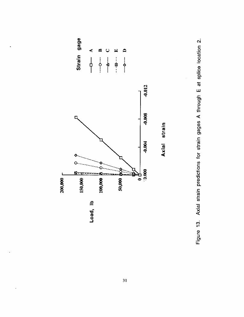
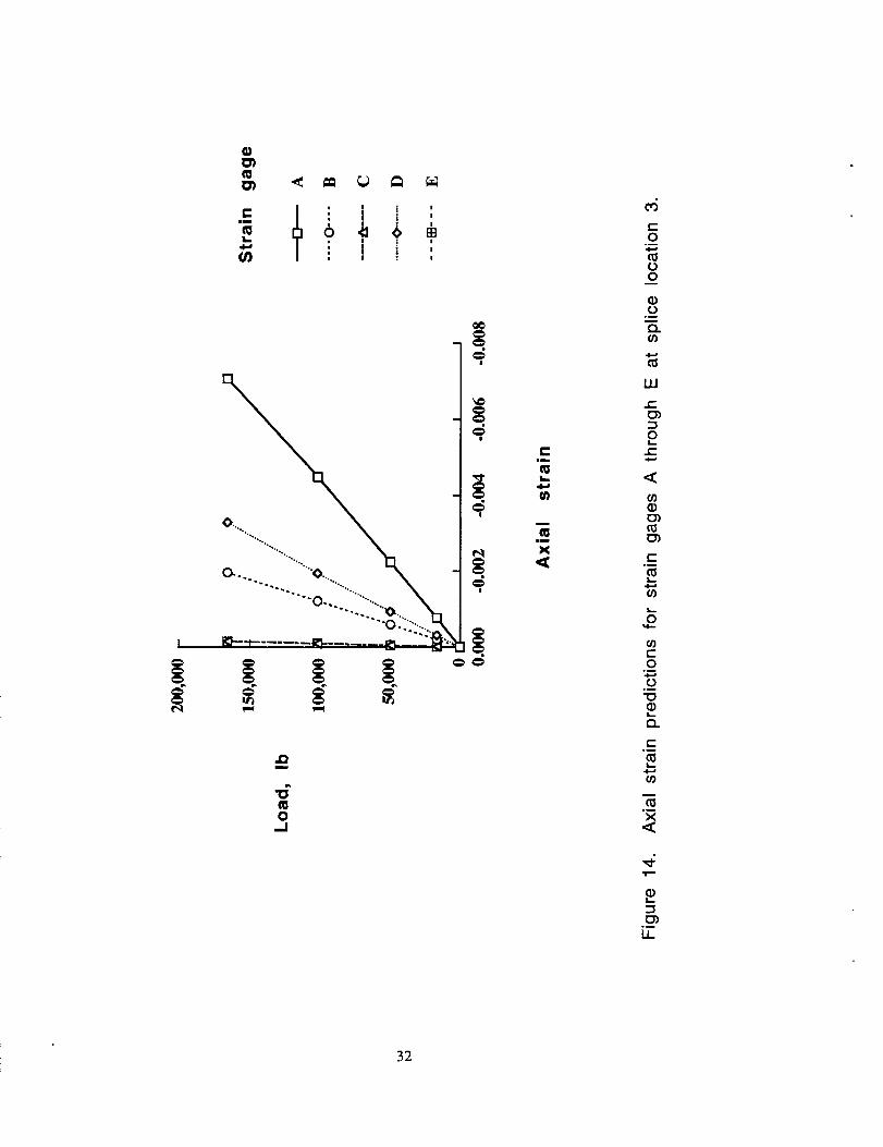
gage E is located on the aluminum outer splice plate. Analytical predictions of
the strain at these strain gage locations are shown in figures 12, 13 and 14 for
splice locations 1, 2 and 3, respectively. The load for the ordinates in the
figures is the load applied at the outboard end of the wing-tip extension
structure. The applied load corresponding to Design Ultimate Load is 166,000
lb. The load-versus-strain curves shown in figures 12-14 indicate that the
maximum strain is predicted to occur at the location of strain gage A, and is
.0081, .0082, and .0071 in/in, at DUL for locations 1, 2, and 3, respectively. The
strains increase almost linearly with load, indicating that geometric effects do
not cause nonlinear response. Applied loads of approximately 195,000 lb,
185,000 Ib, and 220,000 lb would be required for the strain at strain gage A to
equal the unnotched allowable strain of .0093 in/in, at splice locations 1, 2, and
3, respectively. These load levels correspond to margins of safety of .17, .11
and .32, which indicate that failure should not occur at any of these regions
unless the load is 11 percent greater than Design Ultimate Load.
Since the margins of safety in the regionsof the upper cover panel away fromthesesplice locations,such as near the accessdoor, are less than .05 (ref. 6),
failure is not expectedto occur in thesesplice regions
Concluding Remarks
Three compression splice joint regions of the upper cover panel of a graphite-
epoxy wing stub box were analyzed using a finite element analysis. Loads up
to Design Ultimate Load (DUL) were considered. The predicted maximum strain
in each compression splice joint region at DUL is approximately .008 in/in.,
which is less than the allowable strain of .0093 in/in, for the material. The
wing stub box is not expected to fail at these compression splice joint regions
for applied loads up to 11 percent greater than DUL.
References
1. Markus, Alan M.; and Grossheim, Brian G.: Manufacturing Development for
Stitched/RFI Transport Wing Stub Box Structures. Proceedings of the Fifth
NASA/DoD Advanced Composites Technology Conference, NASA CP 3294, pp.
773-786, May 1995.
2. Markus, Alan; Thrash, Patrick; and Grossheim, Brian: Manufacturing
Development and Requirements for Stitched/RTM Wing Structure.
Proceedings of the Fourth NASA/DoD Advanced Composites Technology
Conference, NASA CP 3229, pp. 503-523, 1993.
3. Hinrichs, S. C.: ICAPS Stub Box Structural Analysis Volume 1: Material
Properties. McDonnell Douglas Aerospace Transport Aircraft-West, Report
Number MDC94K9101, March, 1995.
4. Wang, John: Global and Local Stress Analyses of McDonnell Douglas
Stitched/RFI Composite Wing Stub Box. NASA TM 110171, October 1995.
5. Brogan, F. A.; Rankin, C. C.; and Cabiness, H. D.: STAGS User Manual.
Lockheed Palo Alto Research Laboratory, LMSC Report P032594, 1994.
6
6. Hinrichs, S. C.: ICAPS Stub Box Structural Analysis Volume 4: Upper Skin
Strength Analysis. McDonnell Douglas Aerospace Transport Aircraft-West
Report Number MDC94K9101, March, 1995.
7
C
•_ owm
lib
oo _ E
@
°_
Eor,.)
III
III
!
9
I
"0
"0s._
O..QC
m
f=O
Bm
(3O
m
G)(3
wmm
Q.t_CO
im
Q.EO
O
Ii.
[3)_m
IJ=
l0
rlj
,,,I=
.=. i...:v
i I l I I I I I i .... _1\111111 I'll
__JiJlllllllllllllllllJJ_lllrl\l I I I I I II_JiiliiillllllllllllllllJTI I I I I
_'_"L ,_-'_,l, lllll!ll.l!l!l?"-t-q-@, I, I I I II
/ I I # I I / / I # I J } Ji i / I / I I I I I / I // I1 I / # I / I # J t ,
_/--_ f# } "# "#'11#-# #-I I ! + I i It ! I I 1 I [ I I 1 1
_ _ _ l l l # l l l l l # l l l il l l # i l l l l l il_ n l i t l t l I t t l t l II_L I I ! !1111#
Ld_ i i i i i f f f i i I I i I I It J# # P I _ # I t #_
......... : ; " "" 7777;';';';'7 ;/ts+=+e=iYr_,_+,-,.,.:,,/__'_z_ i I s I s I I I
/"l'--/ Ill _ ! ! ! L _" _J _J.=_"_ "_d!!_il._lt, l,._ _ 'l I ', _. _, 'i_ ",. _ ; ; '. 1_
I I I + _r I I..... 1 _ ! # I 1:__" " " • " - - - _ I...Z.J..
!, ,'iN?i� ie¢_ . X_l I I I /
',%' %X XX X X
13 f/ l I I /
rl # i 1 I
/ 1 l # /_
HI/s!
x X\
@
= =@ @
o_om
°" L,)
"--" Oa
Im
11
_ °,-w
o_ml
mini
f.i
Im_ om
12
J
o-, r_
4G_J
]3
dd
i-
,,I,_:.._.l,=],,Jllllllllllll1111_zl:lzl-'_l_ I I I ii
IIIIIIIIItllllllllll_!qllllHTI I I I ii
-"_'L_,_"lJlIlllf_l_l_'Uii+_l ]1 I
em
('4
m
S 0
_j_ o_m
0
L. "CI
m
"t=0
= ;;
0..
"tP = =tma
"" 0= = =0
o _I o
- _
[,_ _
14
0 C=,• • •
*_ _ i____ii_!_i_i_ _,,_!!_,_i_.__ ,_._._. .....
0
00
lllliillll
lif
!
L"'-
I I I I I | I
I
@_m
@
m
L..
@_m
L-.@
m
_m
.,<
:3¢:
@
_m
15
l | | | | ¢ !J
0.m
E
"0 '_
o|
'" ]6
17
m
E
_S
mnl
0
E
0olml
EC_
c_
0m_ml
EC_
imU
0oil
0imm
Bjlill
_J
0
Eomll
mml
_D
"_ _
_ o,-i
E _
omnl
E
E
|i • •
o*m
EL
o
m
L
=
.m
o
q,)
kq
18
|
a_ o_
ollm
E _0 _
m
"0 0
c_
_L
_ Dnu
19
i
_ 0eii
_ iii1i
0 _L
_ =_
E _
_I oll
i
om _I_
oil
mi
0 .=1 __iI ii
.if
°,=l J_
20
0mm
0
gm
21
• ; ; , ; , ,
0om
I_0
m
0
0,
tm
, 22
O00
0 0
!
23
|
i
|
|
!
Imc_
w
.im
1-
u
lw
m
c_I'll
mU
lumm
"o
C_
Eim
m
r_
°_
L.
I--
_c
oo
r
,m
_ 0
,m
24
i
L-
Gi_ -m
L @
.mm
"0
@
• |. |"
=m
i=.m
25
c_
i W
Tm _
k __ 0
ru
om
26
!
r_
olR
om _
J_
otu _i_
_ L
_Dolu
27
m
=0
.=
om
r_
28
W
/I I I I I _ _ _ t I _ \1 I II I I I II
r--___lllil I IIIIIIIIIllliT-T_l I I I I I tl
_1 I illlllllllIILJ_l111_l I I I I I I I_, II I I I I II] l l I I_I]ZI_LLUIJ]I I I I I I I I
_"'L_,r_i, ll, l,l,J,i1111111,1111'II-_l III I I II
II
¢/)c0
lli,I,,,I
0O
i
G)
m
Cit
ml,_
m
G)!--Z3
|w
ii
29

Q_
ilm
I i ! i :
T : I i ,
0-......... 0 ...... _,"
°" "°°°'".°°.°._...°o
_..-°_-'2.........--_!_+:-_----_
I I I
.Qm
O
e"in
,,ll,d
m
im
c-O
.u
RI
O
o
r_
RI
ILl
E3_:3
e{-
<
C_RICn
{-.
O
Oom
C_.
{-
X<
cn
ii
3O
C ' ' I '"_ I : , , !
0
i ......... o-._i'i"............,
m
0.J
e",m
W
n
mm
X
ait-O
0
0
LLI
t--
0
t--
I.-
O
0.m
0"0
t'-
i
X
c6
LL
31
c I i i i :
I : i J :GO I : , ,. ,
_...
0... ""'"0.. _
o
""_o222 ..... ,
m
mo
,.,i
.m
s.._
m
.a
X
0
{..)0
{..)
g,,}
LL,I
o4.0
<_
C_
I,,-
0
c-O
o
c
0"}
X<_
1.1_
32
ii | | i ,,, ,
Form ApprovedREPORT DOCUMENTATION PAGE OMBNo. 0704-0188
Public rl_orling but_r_ for this collection of information is _tlmated.to average 1 hour per response, inck_ling the time for f_vk_tlg instructions, seatctling existing data Iout_,,
g:*her_g ;rod mamtaJnlr_ the dala needed, and completing and rowewlng the coSec'lion ot mlormation, Sendcommenls re_arding tha; burden osllrnate Or any Other alpect of this.collection Of information, mclucUng suggeslions lot reducing thiS burden, to Washington Headquallets Serv;._s, Directorate for tnlormafion Operations and Re_x_s, 1215 Jefferson DavisHighway, Suite 1204. Adinglon. VA 22202-4302. and to 1he Off'co ol Manag_l",er=! and Bu0get, Paperwork Re0uc_ion Prolect (0704-0188), Washington, DC 20503,
1. AGEI_CY USE ONLY (Lmave blank) 2. REPORT DATE
October 19954. TITLE ANDSUBTITLE
Analysis of Selected Compression Splice Joint Locations in aGraphite-Epoxy Transport Wing Stub Box
6. AUTH(3'RiB) ....
Dawn C. Jegley
7. PERFORMINGORGANIZATIONNAME(S)ANDADDRESS(ES)
NASA Langley Research CenterHampton, VA 23681-0001
9. SPONSORING/ MONITORINGAGENCYNAME(S)ANDADDRESS(ES)
National Aeronautics and Space AdministrationWashington, DC 20546-0001
3. REPORTTYPEANDOA1"ESCOVERED
Technical Memorandum
5. FUNDING NUMBERS
WU 510-02-12-01
8. PERFORMING ORGANIZATIONREPORT NUMBER
10. SPONSORING / MONITORINGAGENCY REPORT NUMBER
NASA TM 110170
11. SUPPLEMENTARY NOTES
12a. DISTRIBUTION / AVAILABILITY STATEMENT
Unclassified.Unlimited
Subject Category 39
12b. DISTRIBUTION CODE
13. ABSTRACT (Maxlmum 200 words)
Three critical compression splice joint locations in a stitched graphite-epoxy transport wing stub box have beenanalyzed to determined their expected structural performance. The wing box is represenlative of a section of acommercial transport wing box and was designed and constructed by McDonnell Douglas Aerospace Companyas part of the NASA Advanced Composites Technology (ACT) program. The results of the finite elementanalyses of the splice joints are presented. The analysis results indicate that failure will not occur in the splicejoint regions for loads less than the Design Ultimate Load of the wing box.
_. SUBJECTTERMS
composite materialstitching
finite element analysis
17.SECURITYCLASSIFICATION
bolted joint
18. SECURITY CLASSIFICATION 19. SE_iJI_ITY' CLASSIFICATIONOFREPORT OFTHISPAGE OFABSTRACT
Unclassified Unclassified Unclassified
NSN 7540-01-280-5500
15. NUMBER OF P_,GES
33
16. PRICE CODE
A03
20. LIMITATION OF ABSTRACT
Standard Form 298 (Rev. 2-89)
Pte_:libed by ANSi Bid. Z39-182go- 10_