Embed Size (px)
Citation preview

. .. I . *
N A S A TECHNICAL NOTE
04 04 *o
P n z c 4 c/) 4 z
ANALYSIS OF SEVERAL
FOR MACH 3.0 FLIGHT METHANE-FUELED E N G I N E CYCLES
by Brent A. Miller Lewis Research Center CZeveZand, Ohio
* . b'
4-
N A T I O N A L AERONAUTICS A N D SPACE A D M I N I S T R A T I O N W A S H I N G T O N , D. C. JULY 1968
https://ntrs.nasa.gov/search.jsp?R=19680019906 2018-05-07T06:24:10+00:00Z

TECH LIBRARY KAFB, NM
0333323
P / ANALYSIS O F SEVERAL METHANE-FUELED ENGINE CYCLES
FOR MACH 3.0 FLIGHT
BY Bren t A. Miller,
Lewis R e s e a r c h C e n t e r Cleveland, Ohio
P-
Y NATIONAL AERONAUTICS AND SPACE ADM-N
For sale by the Clearinghouse for Federal Scientific and Technical Information Springfield, Virginia 22151 - CFSTI price $3.00

ABSTRACT
Several means of using methane's heat sink capacity for turbine cooling and for other purposes to improve engine specific impulse, specific thrust, and thrust per unit com- p r e s s o r f rontal a r e a were analyzed. Preheating of the methane with heat sources both internal and external to the engine was considered. In general, small gains in perform- ance w e r e obtained for the various cycles with respect to a reference turbojet cycle. No attempt was made to determine the weights of the various cycles considered.
ii
r
ANALYSIS OF SEVERAL METHANE-FUELED ENGINE CYCLES
FOR MACH 3.0 FLIGHT
by Brent A. M i l l e r
Lewis Research Center
S UMMA RY
The performance of several methane-fueled engine cycles suitable for Mach 3 . 0 flight is analyzed. The heat sink capacity of the fuel is used for turbine cooling as well as for other purposes. The primary figures of merit used for judging engine perform- ance are specific impulse, specific thrust, and thrust per unit compressor frontal area. In accord with the preliminary nature of this study, no attempt is made to determine en- gine weights associated with the various cycles.
a r e used as references in discussing other cycles. cooling is accomplished by passing fuel through the turbine blades.
source before injection into the burner. with respect to the reference cycle. bine to extract useful work and cool the fuel allowing further preheating, increased spe- cific impulse 4. 5 percent. compressor yielded improvements in thrust per unit compressor frontal area of 8 per- cent at Mach 3 . 0 and 13.6 at takeoff. In the final cyqle considered, the engine compres- sor is driven by heating and expanding the methane through a turbine. tential saving in engine weight with respect to the reference turbojet at the expense of specific impulse.
The values of the performance parameters obtained for a methane-fueled turbojet In the reference turbojet, turbine
In the f i rs t cycle considered, the methane fuel is preheated with a nonengine heat This increased specific impulse 3. 2 percent
A variation of the fuel preheat cycle, using a tur-
A cycle using the fuel heat sink to cool the airflow into the
This offers a po-
INTRODUCTION
Efficient flight at supersonic speeds depends on having engines with a high specific impulse and light weight. Studies have indicated (ref. 1) that a methane-fueled turbojet offers about a 13 percent
These characteristics depend on the engine cycle and fuel.
I
improvement in specific impulse over a JP-fueled turbojet.
higher turbine inlet temperatures for a given turbine blade metal temperature. Conse- quently, a smaller engine is required for a specified thrust. Smaller engines usually weigh less than larger ones.
of methane and its heat sink capacity through turbine cooling, still other cycles can be devised to take advantage of these and other properties of the fuel. methane properties of importance are its high specific heat, good thermal stability at high temperatures, and low boiling point. tively good working fluid. Of primary interest here is the application of the available fuel heat sink to other jobs in addition to turbine cooling.
In addition, the large heat sink of methane, if used for turbine cooling, permits
While the conventional turbojet cycle can take advantage of the higher heating value
These additional
These characteristics make methane a rela-
Selected properties of methane (refs. 1 and 2) a r e as follows:
Boiling point (1 a h ) , OR (K) . . . . . . . . . . . . . . . . . . . . . . . . . . . 201 (112) Density (liquid), Ib/cu f t (kg/cu m) . . . . . . . . . . . . . . . . . . . . . . . . 26 (416) Freezing point (1 a h ) , OR (K) . . . . . . . . . . . . . . . . . . . . . . . . . 163 (90.6) Lower heating value, Btu/lb (J/kg) . . . . . . . . . . . . . . . . . . . 2 1 200 ( 4 . 9 2 ~ 1 0 ~ ) Heat sink (initially liquid at 201' R (112 K)), Btu/lb (Jh)
1100 ( 2 . 5 5 ~ 1 0 ~ ) 1630 (3. 78X1O6)
Heat of vaporization ( 1 atm), Btuhb (J/kg) . . . . . . . . . . . . . . . . . 219 ( 5 . 0 9 ~ 1 0 ~ ) Specific heat (liquid), Btuhb OR (J/kg K) . . . . . . . . . . . . . . . . . . . . 0.82 (3429) Stoichiometric fuel-air ratio . . . . . . . . . . . . . . . . . . . . . . . . . . . . 0.0581 Spontaneous ignition temperature, OR (K) . . . . . . . . . . . . . . . . . . 1630 (905.6)
at 1460' R (811 K) . . . . . . . . . . . . . . . . . . . . . . . . . . . . at 2000' R (1111 K) . . . . . . . . . . . . . . . . . . . . . . . . . . .
For this analysis, the quantities of most interest are the fuel's lower heating value (en- thalpy of combustion with oxygen with resultant water considered as a vapor) and heat sink capacity.
This ac- counts for the increased specific impulse as compared to JP. Although the low initial temperature of methane contributes to its excellent heat sink capacity, it detracts from the fuel total enthalpy (enthalpy of combustion plus sensible enthalpy of fuel before com- bustion) that would be observed were the fuel vaporized and preheated to a higher tem- perature. Thus, in effect, the heat sink may be used to increase the fuel's total enthalpy yielding a consequent increase in specific impulse when the preheating is accomplished with a nonengine heat source (external preheating). Another possible use of the fuel heat sink is compressor precool- ing to increase engine airflow, thrust, and specific impulse.
The heating value of methane is about 13 percent greater than that of JP.
However, this can occur when the fuel heat sink is used.
2

The working fluid properties of methane can be used to advantage by expanding the fuel through a turboexpander to partially unload the main turbojet turbine. An expansion of the fuel in a turboexpander increases the heat sink available to the cycle and, hence, the possibility of further increasing the fuel total enthalpy.
pulse, specific thrust, and thrust per unit compressor frontal area. inary nature of this study precludes the determination of actual engine and system weights. The cycle performance comparisons are made at Mach 3.0 in the stratosphere and, in one case, at sea-level static conditions. cycle with direct fuel cooling of the turbine was used as a reference.
In this analysis, a number of engine cycles are compared on the basis of specific im- The rather prelim-
The performance of a methane-fueled turbojet
SYMBOLS
A area, sq ft ; sq m
*tb turbine area requiring cooling, sq f t ; sq m
gas specific heat at constant pressure, Btu/(lb)(OR); J/(kg)(K) cP
F thrust, lb; kg
F/Wa specific thrust, sec (see eq. (5))
f fuel-air ratio
2 2 g acceleration of gravity, ft/sec ; m/sec
h
I
L/D
N
P
Q R
T
V
W
2 2 heat transfer coefficient, Btu/(ft )(sec)(OR); J/(m )(sec)(K)
fuel specific impulse, sec (see eq. (6))
aircraft lift to drag ratio
compressor rotational speed, rpm
total pressure, lb/ft2; N/cm2
heat flow, Btu/sec; J/sec
Breguet cruise range, f t ; m
total temperature, OR; K
velocity, ft/sec; m/sec
weight, lb; kg
3

W weight flow, lb/sec; kg/sec
WG
Y ratio of specific heats
6
r adiabatic efficiency, percent
e Subscripts:
aircraft weight at start of cruise, lb; kg
ratio of total pressure to standard sea-level pressure, P1/2116; P1/lO. 13
ratio of total temperature to standard sea-level temperature, T1/518. 7; T1/288
A heat exchanger A
a air
B heat exchanger B
C compressor
E exhaust
e engine
f fuel
t turbine
tb turbine blade
0 free stream
1 compressor inlet
2 compressor exit
3 turbine inlet
4 turbine exit
Superscripts:
n engine weight exponent
* denotes change in quantity from reference value
METHOD OF ANALYSIS
Figures of Merit
The present analysis considers the performance of a number of methane-fueled en-
4
. ... .... _ _ .- .... >.. . . . . ..... .,...--..--...- I I., . ,..

gine cycles that may be applicable to supersonic cruise aircraft. The primary figures of merit used herein fo r judging engine performance are specific impulse I, specific thrust Ffia, and thrust per unit compressor frontal area F/Ac. These were evaluated at Mach 3.0 in the stratosphere and, in one case, at sea-level static conditions.
can be shown by considering cruise range. The relation of the engine performance parameters chosen to aircraft performance
The Breguet range equation
shows that range is proportional to specific impulse. analysis, a 1 percent improvement in cruise specific impulse leads to a 1 percent im- provement in cruise range. This implies that the product of cruise velocity and cruise lift to drag ratio remains constant and that the aircraft weight at the start of cruise and cruise fuel also are constant.
cycle considered, the effect of changes in specific thrust and thrust per unit compressor frontal a r ea can be shown by assuming a weight scaling law. law is used that assumes engine weight varies with compressor frontal a rea as follows:
Thus, for instance, in a simplified
Although no attempt w a s made to calculate the weights associated with each engine
To illustrate this, a scaling
For a constant engine thrust, (i. e., F = F*) the equation may be rewritten as:
w2: -
we - -
n
(3)
Equation (3) can accommodate both changes in specific thrust and thrust per unit compressor frontal area. If aircraft payload as well as aircraft gross weight at the start of cruise and cruise thrust are assumed constant, the Breguet range equation may be written as follows to show the effect of changing engine weight.
5

Thus, for example, this equation, along with equation (3), shows that if engine thrust per unit compressor frontal area is increased from F/Ac to (F/Ac)*, an increase in cruise range is obtained. A similar statement applies to specific thrust. However, if the specific impulse is reduced in obtaining these increases, the range may or may not be improved.
The preceding discussion shows how cruise range is affected by the engine perform- ance parameters investigated. In general, the most useful aircraft performance param- eters will depend on the particular aircraft and mission considered. Range was used in this discussion as an example.
Basic Cycle Relations
The basic engine cycle performance parameters of interest here a r e the specific thrust F / G ~
wa
(where the exhaust flow is fully expanded) and specific impulse I
The quantities required in these relations a re the exhaust velocity VE and the fuel to air ratio f. These are obtained from an analysis of the engine cycle. cedures and relations used in calculating cycle performance a r e valid for all the cycles studied herein and may be found in reference 3.
properties y and C
The basic pro-
Compression and expansion processes were analyzed using average values of the gas For instance, the compressor exit temperature T2 given by
P'
6

T1 T2 =11
was found for the y corresponding to the temperature T = (T1 + T2)/2 by an iteration process. Similarly, the power required to drive the compressor, given by
Compressor power = W C (T2 - T1) a P
was found for an average C nozzle were treated in a similar manner.
tions involving the combustion of fuel with air. air ratio f and the gas properties C and y .
Expansions through the turbine and the fully expanded P'
The method and tables of reference 4 were used to perform thermodynamic calcula- The quantities obtained here are the fuel
P
Turbojet Cycle
The assumed component characteristics of the turbojet cycle are presented in table I for Mach 3.0 flight in the stratosphere and for sea-level static conditions. cycle compressor map is shown in figure 1. pressure ratio is 9.9. pressor yields a pressure ratio of 3. 5 at Mach 3.0 in the stratosphere. ing compressor efficiencies are, respectively, 87 and 83.2 percent.
The The sea-level static design compressor
For operation at a constant mechanical speed N the same com- The correspond-
Although the comparative nature of this study makes the selection of engine char-
TABLE I. - TURBOJET ENGINE CHARACTERISTICS
I Characteristic I Mach 3.0 [ S e a - l e v 4
I Inlet pressure recovery I 0.85 Compressor pressure ratio 3. 5 Compressor adiabatic efficiency 0. 832 Corrected weight flow, percent 51 Combustor pressure ratio 0.94 Combustor efficiency 0. 98 0. 98 Turbine efficiency 0.867 0.867 Nozzle thrust coefficient 0. 98 0.98
7

Compressor corrected weigh; flow, (Wi%)/6, percent of design
Figure 1. - Turbojet compressor map.
acteristics somewhat arbitrary, the values selected a r e typical of those that yield good airplane performance considering both takeoff and climb as well as sustained Mach 3.0 cruise. Even though afterburning may be required during the transonic climb and accel- eration phase of flight, the engine performance presented in the present analysis as- sumes maximum dry thrust at takeoff and during cruise.
Turbine cooling. - Turbine cooling was considered for the turbojet engine cycle. Turbine inlet gas temperature T3 was varied over the range 2200' R (1222 K) to 3260' R (1811 K) -with a heat input to the turbine given by the expression:
The cooling load was found by assuming that a turbine blade metal temperature Ttb of 2200' R (1222 K) is acceptable.
The first method discussed is shown by the turbojet cycle of figure 2. Here turbine cooling is accom- plished with compressor bleed air. The fuel heat sink is used to cool the bleed air in order to reduce the amount of compressor bleed air required. No bleed is required if the turbine inlet gas temperature is equal to or less than the allowable turbine metal temperature of 2200' R (1222 K). Detailed turbine cooling studies of the type of refer- ence 5 indicate that a compressor bleed flow of approximately 6 percent is required at a
Two methods of accomplishing turbine cooling are considered.
8

r
,-Heat exchanger
Station 1 3 4
Figure 2. - Turbojet us ing compressor bleed a i r and fuel heat s ink for tur- bine cooling. Typical Mach 3.0 cycle temperatures are shown.
turbine inlet temperature of 2660' R (1478 K). Taking this as a reference point, the schedule of compressor bleed flow with turbine inlet gas temperature shown in figure 3 was obtained by taking a linear variation of bleed air with temperature difference above the allowable blade metal temperature of 2200' R (1222 K). At a turbine inlet tempera- ture of 2600' R (1444 K), figure 3 shows that a bleed flow of approximately 5 percent is required for turbine cooling.
turbojet cycle of figure 4. This cycle uses the fuel heat sink in a turbine blade heat ex- changer to cool the turbine. that a turbine inlet temperature of 3260' R (1811 K) will require all the heat sink avail- able in heating the methane from a liquid at 201' R (112 K) to a gas at 1460' R (811 K). The percent of the heat sink required at other turbine inlet temperatures was then found as follows.
must equal the heat absorbed by the fuel 9. tional to the fuel flow rate and the percent of the available heat sink used for turbine cooling.
The second method considered for accomplishing turbine cooling is shown by the
It was estimated No compressor bleed a i r is required.
At equilibrium operating conditions, the heat absorbed by the turbine blades &tb The heat absorbed by the fuel is propor-
Qtb = 9 cc Wf (Percent heat sink) (10)
The engine fuel consumption rate is proportional to the airflow and the temperature in- crease in the combustor.
Wf "Wa(T3 - T2)
The turbine area cooled Atb was assumed to be proportional to the turbine annulus area. For a constant flow Mach number, this area is proportional to airflow and the
9

Fuel, 201" R (112 K) I r
900" R Turbine cooling (500 K) loop w i th blade
(600 K) -<
A i r
cal Mach 3.0 cycle temperatures are shown.
heat exchanger 1080"RUr, 1600" R 2600" R
(889 K) , < (1444 K) Heat-" Exhaust 0 exchanger ' <
14
g 12 - L L
m L 0 YI
._
10 2
5 8
0 v
0 c
c
5 W n
oi (3 .- - 0 6 0 La
a c n L ._
5 4 L
0
V W .n L
c
- ._ a 2
0 2200 2400 2(
,/
2
i
/
3 Turbine-inlet temperatun
/ / /
3; 'R
I
/
U I I 1300 1400 1500 1600 1700 1800
Turbine-inlet temperature, K
0
Figure 3. - Turbojet compressor bleed a i r required for tu rb ine cooling. Blade metal temperature, 2200" R (1222 K) (see fig. 2).
10

square root of temperature. Thus,
Equation (10) can be solved with the aid of equations (9), (ll), and (12) to give the fuel heat sink required for turbine cooling at any turbine inlet temperature.
100
80
60
4c
c
: 2c ? a, a
x- c ._ " C c m a, r
/'
/
/
i / / i
-
601 I 7 I 0 V'
2200
(a) Maximum fuel preheat temperature, 1460" R (811 K).
I l l
I l l I I/( 1/1
i l l
'I I 2400 2600 2800 3000
Turbine-inlet temperature, "R
I I I I 1- 1300 1400 1500 1600 17Ol
(b) Maximum fuel preheat temperature, 2000" R (1111 K).
Figure 5. - Percentage of fuel heat s ink required for reference turbo- jet tu rb ine cooling. Mach 3.0 in stratosphere; blade metal tempera- ture, 2200" R (1222 K); in i t ia l methane temperature 201" R (112 K) (see fig. 4).
Turbine- in let temperature, K
11
I

The proportionality constant may be found since it was estimated that a turbine inlet tem- perature of 3260' R (1811 K) will require 100 percent of the heat sink available in heating the methane from a liquid at 201' R (112 K) to a gas at 1460' R (811 K).
versus turbine inlet temperature for a maximum methane preheat temperature of 1460' R (811 K). The total heat sink available is 1100 Btu per pound of fuel (2. 55x10 J /kg) if the fuel is initially a liquid at 201' R (112 K). Figure 5(b) shows the percent of the fuel heat sink required to cool the turbine for a maximum methane preheat temperature of 2000' R (1111 K) where the heat sink available is 1630 Btu per pound of fuel (3.78X10 J/kg). The limiting temperatures of 1460' R (811 K) and 2000' R (1111 K) were arbitrarily chosen to indicate the sensitivity of cycle performance to changes in maximum permissible fuel pre- heat temperature. lecting the practical operating limits.
modifications to the methods previously described. description of the special cycles.
Figure 5(a) shows the percent of the fuel heat sink required for turbine cooling
6
6
An acceptable fuel decomposition rate would be a major factor in se-
Some of the special cycles to be discussed in the RESULTS AND DISCUSSION require These modifications a r e noted in the
RESULTS A N D
Performance of
DISCUSS I ON
Y u r bojet C yc I e
Figure 6 presents the performance of several turbojet cycles a t Mach 3.0 in the Engine performance, in terms of specific impulse and specific thrust, is
The upper line with the open symbols gives the performance of the turbojet
stratosphere. shown for a range of turbine inlet temperatures from 2200' R (1222 K) to 3260' R (1811 K). cycle with direct fuel cooling of the turbine, the cycle shown in figure 4. For this cycle, the peak specific impulse occurs at a turbine inlet temperature of approximately 2600' R (1444 K). The corresponding values of specific impulse and specific thrust are, respec- tively, 2790 and 40. 1 seconds. These values a r e used as a reference for comparison with the other cycles investigated.
The closed symbols on the upper line show the turbojet performance if no turbine cooling is required. Compared to this case, turbine cooling directly with the fuel (the upper curve with open symbols) does not change the variation of specific impulse with specific thrust. However, turbine cooling does cause the peak specific impulse to occur
12

280
* 275 %
5 - -
270 ._ " " m
._ c ._
5: 265
260
k
Turbine i n le t I I I I I
"R (K) -
- 0 2200 ( 1222) 0 2400 (1333)
- A 2600 (1444) n 2800 (1555) b 3000 (1667)
- n 3260 (1811) -Open symbols denote direct f ue l
cooling of tu rb ine (see fig. 4) -Closed symbols denote no tu rb ine
cooling -Tailed symbols denote bleed a i r
for turbine I I
\ I I ttyt I Y \
I l l \ i p I 50
rig. 2) I Specific thrust, F/Wa, sec
bine cooling. Mach 3.0 i n stratosphere. Figure 6. - Turbojet cycle performance with several methods of t u r -
at a slightly higher turbine inlet temperature. bine cooling causes a slight reduction in specific thrust. turbine cooling would require a substantial improvement in turbine materials.
jet cycle where the fuel heat sink is used to cool compressor bleed air which, in turn, cools the turbine, the cycle of figure 2. With this cycle, the specific impulse is about 1 percent less and the specific thrust is about 1.2 percent less than the reference cycle at 2600' R (1444 K). performance calculations of reference 1.
If turbine inlet temperature is fixed, tur- In practice, the elimination of
The lower curve of figure 6 with tailed symbols shows the performance of the turbo-
This cycle, using compressor bleed air, was used for the airplane
Turbojet Cycle With External Preheating of the Fuel
The turbojet cycle with external preheating of the fuel is shown in figure 7. It differs from the reference turbojet cycle of figure 4 by the addition of heat exchanger A to the fuel system. This section and following sections discuss engine cycles which take advantage of methane's heat sink, thermal stability, and ability to be vaporized and used
13

I 1460" R
Heat exchanger A 3
1
Figure 7. - Turbojet cycle wi th external preheating of fuel. Typical Mach 3.0 cycle tempera- tures are shown.
as a working fluid for other purposes in addition to turbine cooling.
consider preheating of the fuel with a heat source external to the engine. Several sources of heat external to the engine are available. tion, stagnation temperatures on the order of 1080' R (600 K) a r e encountered. Thus, aerodynamic heating of the fuel could possibly be obtained by placing heat exchangers at strategic locations in the airframe. Other potential heat sources commonly requiring cooling could also be used. Several of the major sources include hydraulic fluid and pumps, electrical equipment, and the cabin or crew area. In light of the sources avail- able, it was assumed that, if desired, sufficient energy could be obtained from sources external to the engine to preheat the fuel from a liquid at 201' R (112 K) to a gas at 1000° R (556 K). If this temperature rise is obtained from aerodynamic heating, the required heat exchanger effectiveness (defined as obtained temperature r i se divided by maximum theoretical temperature rise) is 9 1 percent.
Temperatures in excess of 1000° R (556 K) can be obtained by cooling the hot parts of the engine. Energy obtained in this manner was charged to the cycle. Unless stated otherwise, the component characteristics of the cycles to follow are identical to those of the reference turbojet cycle (see table I and fig. 1).
Effect of turbine cooling on - fuel -. . preheating. - -. - __ - The heat that may be added to the fuel is not only a function of the external source temperature but (when turbine cooling is con- sidered) also of the turbine inlet temperature and the limiting maximum fuel preheat tem- p e r atur e.
The relation of turbine cooling to the degree of external fuel preheating possible can be seen by referring again to figure 5(a), which is for a maximum methane preheat tem- perature of 1460' R (811 K). (1444 K), 56 percent of the available heat sink is required for turbine cooling. The tur- bine cooling can be done with the higher temperature end of the fuel's heat sink capacity. The additional heat QA that the fuel may absorb is the remaining 44 percent of the heat
Heat sources. - The cycle discussed in this section and cycles to be discussed later
For example, at the Mach 3.0 cruise condi-
- - ._
For example, at a turbine inlet temperature of 2600' R
14

c
6 sink or, in this case, 484 Btu per pound of fuel (1. 12x10 J/kg). This enthalpy change can be obtained by externally preheating the fuel from a liquid at 201' R (112 K) to a gas at 700' R (389 K). Hence, even though an external source is available at 1000° R (556 K) when the aircraft is cruising at Mach 3.0, total heat sink considerations and turbine cooling requirements res t r ic t the allowable fue l external preheat temperature to 700' R (389 K) for this example.
methane external preheat temperatures shown in figure 8. maximum methane preheat temperature of 1460' R (811 K) the fuel may be externally preheated to 1000° R (556 K) only if the turbine inlet temperature is equal to or less than 2430' R (1350 K). As turbine inlet temperature is increased, turbine cooling require- ments reduce the permissible external preheat temperature from 1000° R (556 K) at the turbine inlet temperature of 2430' R (1350 K) to 201' R (112 K) at a turbine inlet temper- ature of 2910' R (1617 K). As the turbine inlet temperature is further increased toward 3260' R (1811 K), the permissible heat input to the fuel from heat exchanger A is reduced to the point where less than 100 percent of the fuel is vaporized; thus, there is no fuel temperature rise in this region.
2000' R (1111 K), figure 8 shows that the fuel may now be externally preheated to 1000° R
The procedure outlined i n the previous paragraph was used to obtain the allowable This figure shows that for a
If the maximum methane preheat temperature is increased from 1460' R (811 K) to
a- m L
3
m c L W c
3 400
E
W c m
r a, 200
VI ._ VI E .- E E [ 0
2200
I I
2400
1
Maximum methane - temperature,
Turbine-inlet temperature, "R
I I I L I
I 3400
1300 1400 1500 1600 1700 1800 Turb ine in le t temperature, K
Figure 8. - Effect of tubine- in let temperature o n permissible methane external preheat temperature. Turbine cooling to maintain 2200" R (1222 K) blade metal temperature; Mach 3.0 in stratosphere.
15

(556 K) at turbine inlet temperatures as high as 3100' R (1722 K). fuel preheat temperatures, the external energy that may be added to the fuel becomes identical to its heat sink capacity at a turbine inlet temperature of 2200' R (1222 K) where no turbine cooling is required. Jf no upper limit is set on the permissible fuel preheat temperature, it may be preheated to 1000° R (556 K) for all turbine inlet temperatures considered.
Effect of fuel preheating. - The increased total enthalpy of the fuel obtained by this external preheating will reduce the fuel-air ratio f and, consequently, as shown by equation (6), increase the engine specific impulse I. impulse over that of the reference turbojet obtained by external preheating of the fuel is shown in figure 9. vertical segment of the curve (constant preheat temperature of 201' R (112 K)) shows the
For both maximum
The percent increase in specific
The turbine inlet temperature was fixed at 2600' R (1444 K). The
c S -
a V I a cL
a- m - 3 -
E .- .- v L 1-
% a - Y)
S ._ z c z m
0 -
0
8-
-
7-
-
6-
5 -
4-
3 -
2-
-
1-
~
- Methane external preheat temperatur
I I I I 200 400 600 800
1
'R
I 1000
21 0
Methane external preheat temperature, K
Figure 9. - Increase in specific impulse obtained by preheat- i ng methane fuel wi th heat source external to engine. Ref- erence specific impulse, 2790 sec; turbine- in let tempera- ture, 2600" R (1444 K); Mach 3.0 in stratosphere.
16

specific impulse gain obtained by adding enough external heat to vaporize the fuel. ternal preheating of the fuel to 700' R (389 K), the temperature consistent with the turbine cooling requirement and a 1460' R (811 K) maximum methane temperature, yields a gain in specific impulse of 2.2 percent. If the maximum methane preheat temperature is in- creased f rom 1460' R (811 K) to 2000' R (1111 K), the allowable external preheat temper- ature to satisfy the turbine cooling requirement becomes 1420' R (789 K). This is more than adequate to allow the fuel to be preheated to the 1000° R (556 K) limit assumed to be imposed by the available external source. In this case, a 3.2 percent gain in specific im- pulse is possible (fig. 9). Not shown is a loss in specific thrust and thrust per unit com- pressor frontal a r ea of approximately 0.2 percent due to the reduced fuel flow and, hence, engine mass flow obtained with the lower fuel-air ratio.
If the constraints of a limiting maximum fuel preheat temperature and limited ex- ternal source temperatures are removed, figure 9 shows that external preheating of the fuel to 2000' R (1111 K) could yield a specific impulse gain of nearly 8 percent. Asso- ciated with this is a loss in specific thrust of approximately 1 percent. present Mach 3.0 study, an external source at this temperature is not available.
with a turbine inlet temperature of 2600' R (1444 K). formance, specific impulse versus specific thrust, of the turbojet with fuel preheating for a range of turbine inlet temperatures.
Ex-
'
However, for the
Effect of turbine inlet temperature. - The results of figure 9 were for a turbojet Figure 10 presents engine per-
The lower line gives the performance of the reference turbojet cycle which uses di-
I I I / I 1 I I
preheat cycle;
eference turboiet -cycle
I 30
(fig. 4)
I l l I l l
40 Specific thrust, F
\
\. \
7 ' Turdine- in let
tempera t u re, "R (K)
0 2200 (12221 0 2400 (1333) 0 2430 (1350) A 2600(1444)
2800 (15551
0 3100 (1722) n 3000 (16671
n 32po(i8ii) i I Makimum methan t
60 70
Figure 10. - Turbojet cycle performance obtained by externally pre- heating fuel with 1000" R (556 K) heat source. Mach 3.0 i n strato- sphere.
17
I
rect fuel cooling of the turbine and was previously discussed in regard to figure 6. The uppermost line shows the performance obtained by preheating the fuel with an external source with the maximum methane temperature limited to 2000' R (1111 K). Along this line, the fuel can be externally preheated to 1000° R (556 K) until a turbine inlet temper- ature of 3100' R (1722 K) is reached. Above this turbine inlet temperature, reduced pre- heating is required to accommodate turbine cooling. At the reference turbine inlet tem- perature of 2600' R (1444 K), a 3.2 percent gain in specific impulse is available.
The middle curve connecting the upper and lower curves of figure 10 shows the per- formance obtained with the preheat cycle with the maximum methane temperature limited to 1460' R (811 K). Below a turbine inlet temperature of 2430' R (1350 K), the fuel can be externally preheated to 1000° R (556 K) and turbine cooling then accomplished without exceeding the maximum fuel temperature of 1460' R (811 K). In this region, the per- formance thus coincides with that obtained for the case with a maximum fuel tempera- ture of 2000' R (1111 K). Above a turbine inlet temperature of 2430' R (1350 K), re- duced external preheating is required to accomplish turbine cooling. As the turbine inlet temperature is increased above 2430' R (1350 K), the performance of this cycle ap- proaches that of the reference turbojet. At a turbine inlet temperature of 3260' R (1811 K) where all of the heat sink is required for turbine cooling, the performance of the turbojet cycle with external preheating of the fuel coincides with that of the reference turbojet. At the reference turbine inlet temperature of 2600' R (1444 K), a 2.2 percent gain in specific impulse is obtained with the maximum methane temperature limited to 1460' R (811 K).
If the maximum methane preheat temperature is increased to 1680' R (934 K), oper- ation is possible along the uppermost curve of figure 10 to a turbine inlet temperature of 2600' R (1444 K). This yields near maximum specific impulse with a gain over the ref- erence turbojet of 3.2 percent as quoted previously.
Turbojet Cycle Wi th External Preheat ing of t h e Fuel Augmented by Fuel Expansion
The purpose of this cycle is to improve engine performance by adding more heat to
The cycle is shown in figure 11 and differs from the one shown in fig- the methane from the external sources while maintaining the same source temperature of 1000° R (556 K). ure 7 by the addition of a turboexpander and heat exchanger B to the fuel system. Al- though heat exchanger B is not required over the entire range of turbine inlet tempera- tures considered, it is included in the general discussion of the cycle and is required at low turbine inlet temperatures where turbine cooling requirements a r e small. At the reference turbine inlet temperature of 2600' R (1444 K), the cycle operates in the follow- ing manner.
18
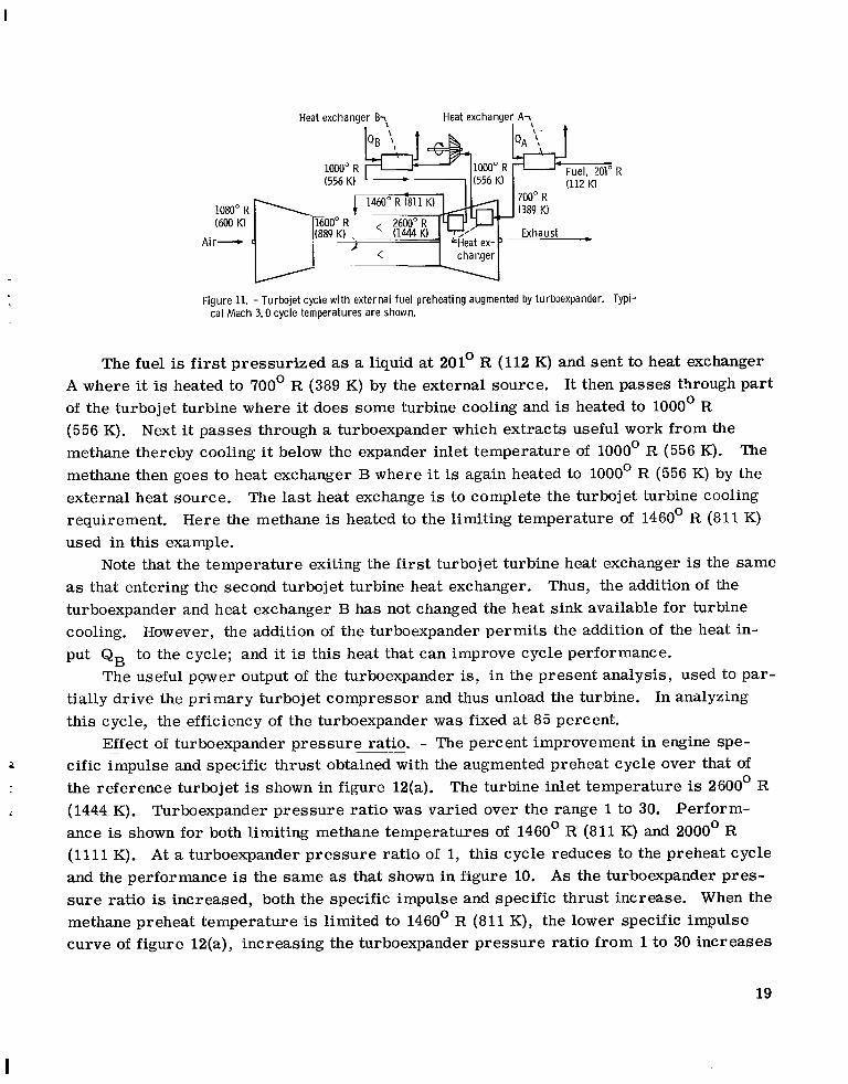
Heat exchanger BT. Heat exchanger AT
Figure 11. - Turbojet cycle w i th external fuel preheating augmented by turboexpander. Typi- cal Mach 3.0 cycle temperatures are shown.
The fuel is first pressurized as a liquid at 201' R (112 K) and sent to heat exchanger A where it is heated to 700° R (389 K) by the external source. It then passes through part of the turbojet turbine where it does some turbine cooling and is heated to 1000° R (556 K). methane thereby cooling it below the expander inlet temperature of 1000° R (556 K). The methane then goes to heat exchanger B where it is again heated to 1000° R (556 K) by the external heat source. The last heat exchange is to complete the turbojet turbine cooling requirement. Here the methane is heated to the limiting temperature of 1460' R (811 K) used in this example.
as that entering the second turbojet turbine heat exchanger. turboexpander and heat exchanger B has not changed the heat sink available for turbine cooling. put QB to the cycle; and it is this heat that can improve cycle performance.
tially drive the primary turbojet compressor and thus unload the turbine. In analyzing this cycle, the efficiency of the turboexpander was fixed at 85 percent.
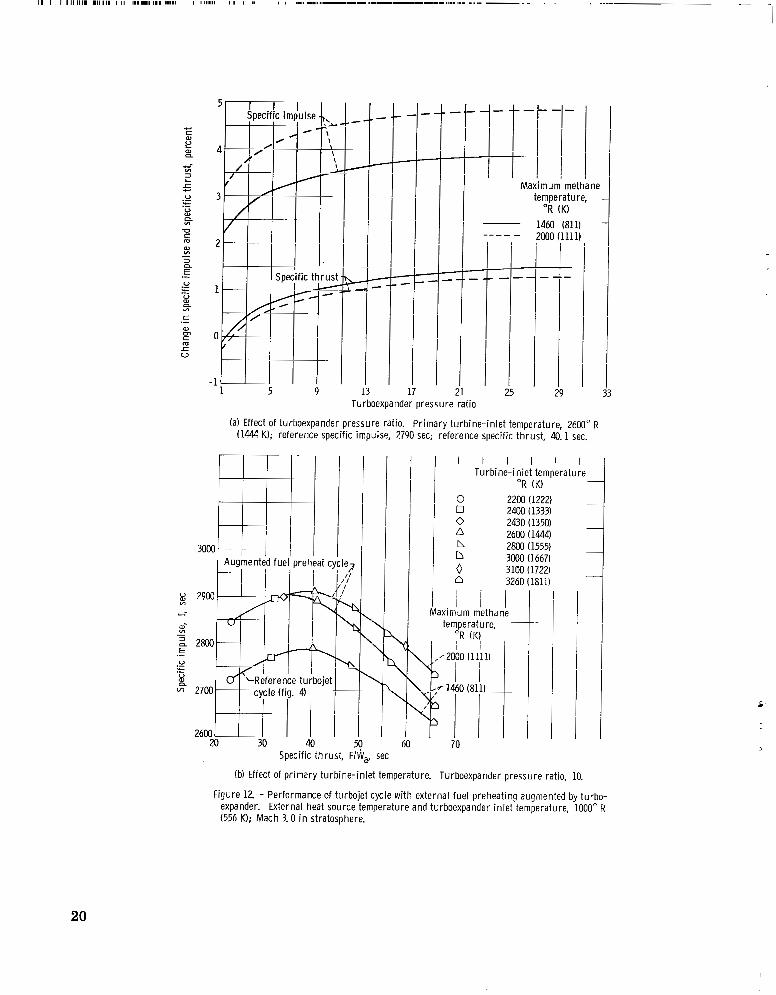
Effect ~- - of turboexpander pressure ratio. - The percent improvement in engine spe- cific impulse and specific thrust obtained with the augmented preheat cycle over that of the reference turbojet is shown in figure 12(a). The turbine inlet temperature is 2600' R (1444 K). Turboexpander pressure ratio was varied over the range 1 to 30. Perform- ance is shown for both limiting methane temperatures of 1460' R (811 K) and 2000' R (1111 K). At a turboexpander pressure ratio of 1, this cycle reduces to the preheat cycle and the performance is the same as that shown in figure 10. As the turboexpander pres- su re ratio is increased, both the specific impulse and specific thrust increase. When the methane preheat temperature is limited to 1460' R (811 K), the lower specific impulse curve of figure 12(a), increasing the turboexpander pressure ratio from 1 to 30 increases
Next it passes through a turboexpander which extracts useful work from the
Note that the temperature exiting the first turbojet turbine heat exchanger is the same Thus, the addition of the
However, the addition of the turboexpander permits the addition of the heat in-
The useful power output of the turboexpander is, in the present analysis, used to par-
-2
19
, .__- _ _ - I 1 I I 1 1 1 11111 111111, I I1 1,111.11I,I 1.111 I 11111111 I I I II I I 1.11 1-.11.1---1--.-----..-..-..... .... ..--.- . . I
1 5
-+-I- l l it
I I I I
- t-t-I- I I I I I
Ti i I Maximum methane
temperature, O R (K)
I 1 I I - 1464 (811)
I I - ----
I I iL
I l l 1 21 25
--I- -
I l l 1 I I O I l l 1
111
- -
Turboexpander pressure rat io
(a) Effect of turboexpander pressure ratio. Pr imary turbine- in let temperature, 2600" R (1444 K); reference specific impulse, 2790 sec; reference specific thrust, 40.1 sec.
3000
u 2900 3 ti
W- m - 2 2800 E .- V
V 0)
.- - .- n * 2700
2600 20 30 40
Specific thrust, FI
.\ '\
\
, set
'i L \
\
6
I I I I I I Turbine-inlet temperature
O R (K) 0 2200 (1222) 13 2400 (1333) 0 2430 (1350) n 2600 ( 1444) n 2803 (1555) 0 3000 (1667) 0 3100 (1722) 0 3260 (1811) ' / I i i i ...- x i mum met ha ne
(b) Effect of pr imary turbine- in let temperature. Turboexpander pressure ratio, 10.
Figure 12. - Performance of turbojet cycle wi th external fuel preheating augmented by turbo- expander. External heat source temperature and turboexpander in le t temperature, 1000" R (556 K); Mach 3.0 in stratosphere.
20

the specific impulse gain from 2.2 to 3.9 percent. impulse gain for a limiting methane temperature of 2000' R (1111 K) a r e 3.2 and 4.9 per- cent. The increase in specific thrust is about 1.7 percent in each case.
The most rapid improvements in cycle performance with increases in turboexpander pressure ratio occur at the lower pressure ratios. A turboexpander pressure ratio of 10 was selected to show the effect of turbojet turbine inlet temperature on cycle perform- ance. At this pressure ratio and Mach 3.0 cruise at 65 000 feet (19 815 m), the required fuel pressure into the turboexpander is 1200 pounds per square inch (827 N/cm ).
Effect of turbine inlet temperature. ~ _ _ - The performance of the augmented preheat cy- cle with a turboexpander pressure ratio of 10 is shown i n figure 12(b) over a range of tur- bine inlet temperatures. Again the performance of the reference turbojet cycle, the lowest line, is given for comparison. tained with the augmented preheat cycle for a maximum methane temperature of 2000' R (1111 K). At the reference turbine inlet temperature of 2600' R (1444 K), a gain in spe- cific impulse of 4. 5 percent is obtained with respect to the reference turbojet. Specific thrust is increased 1.0 percent. In a manner analogous to that discussed in conjunction with figure 10, the energy that may be added to the fuel is reduced as turbojet turbine in- let temperature is increased. This can be illustrated by considering the performance of this cycle with the maximum fuel temperature limited to 1460' R (811 K). The resultant performance, as shown by the middle curve of figure 12(b), is reduced below that of the 2000' R (1111 K) methane temperature case as the turbine inlet temperature is increased above 2430' R (1350 K). At the reference turbine inlet temperature of 2600' R (1444 K), the gain in specific impulse is 3. 5 percent as compared to the 4. 5 percent gain obtained with the higher allowable methane temperature. Gains in performance a r e obtained with respect to the reference turbojet cycle over the entire range of turbine inlet temperatures due to the work extraction and cooling process in the turboexpander. This cooling per- mits additional heat to be added to the fuel at all turbine inlet temperatures considered.
inlet temperature of 2600' R (1444 K) if a maximum methane temperature of 1680' R
The corresponding values of specific
2
The uppermost line shows the performance ob-
The specific impulse gain of 4. 5 percent can be obtained with this cycle at a turbine
4 (934 K) is permitted.
f
Turbojet Cycle With Compressor Precooling
The compressor precooling cycles shown in figures 13(a) and (b) use a heat exchanger or ser ies of heat exchangers ahead of the compressor to cod1 the inlet air prior to its entering the engine. at Mach 3.0 cruise (fig. 13(a)) and sea-level static conditions (fig. 13(b)). At Mach 3.0, it is assumed that the methane coolant flow rate is equal to the fuel flow rate to the en-
Unlike the previous cycles considered, this cycle was analyzed both
21

. . . ,....-,.,.,,., , . , , , ,....--.... . . . ...
# 1080" R /' 10520 R\ c changer
L Heat exchanger
(a) Operation at Mach 3.0 cruise.
- - I
500" R (278 K)
I , I
t changer)
190" R '0°" (111 K) (105 K)
tank
(b) Operation at sea level static with rec i rcu lat ion of fuel.
Figure 13. - Turbojet cycle wi th compressor precooling.
gine. At sea-level static conditions, increased fuel flow rates and, hence, additional cooling were obtained by recirculating fuel from and to the fuel tanks in addition to using the fuel as it flows to the engine.
For a constant compressor rotational speed N, a reduction in the compressor inlet temperature T1 will lead to an increase in the corrected speed N/(8)ll2. From fig- ure 1, it is seen that, for the operating line used, this will increase both the compressor pressure ratio P2/P1 and the corrected weight flow Wa (e) l l2/6. The ratio of com- pressor weight flows for the precooled and the reference turbojet cycle is given by the expression:
wa " 6
p1
where the pressure ratio through the heat exchanger is represented by the te rm Pf/P1. The asterisk denotes the precooled cycle. This change in weight flow as a result of cool-
22

ing can be used to compute the percent change in thrust per unit compressor frontal area by
This quantity, in addition to specific impulse and specific thrust, is a figure of merit for r this cycle.
Operation at Mach 3.0. - At the Mach 3.0 cruise condition, only the fuel consumed by the engine was passed through the heat exchanger. At a turbine inlet temperature of 2600' R (1444 K) with the methane limited to a maximum temperature of 1460' R (811 K), sufficient heat sink is available to cool the compressor inlet air 28' R (15. 5 K) from 1080' R (600 K) to 1052' R (584 K) (see fig. 13(a)). pressure ratio from 3. 50 to 3. 57. obtained. In accomplishing this cooling, the fuel is vaporized and heated 'to 700' R (389 K). preheating of the fuel to 1460' R (811 K).
compressor frontal area obtained as a result of this 28' R (15. 5 K) compressor inlet tem- perature reduction is shown in figure 14(a). The change in performance is plotted against the air side pressure loss through the air-fuel heat exchanger. cooling, the method of reference 6 yields a theoretical pressure loss associated with heat transfer of 0.4 percent. tween the heat transfer coefficient and the wall friction coefficient. A t this pressure loss, the improvements in specific impulse and specific thrust a r e 0. 55 and 1.2 percent, re- spectively. The most significant gain is an increase in thrust per unit compressor frontal area of 4.8 percent. A heat exchanger total pressure loss of 4.3 percent would negate this gain. Increases in specific impulse, specific thrust, and thrust per unit compressor frontal area of 0.8, 1. 7, and 8.0 percent, respectively, a r e obtained if the maximum al- lowable methane temperature is increased to 1680' R (934 K). In this case, the methane is preheated to 1000° R (556 K) in cooling the compressor airflow 40' R (22.2 K).
~~ Sea-level ~ static ~ operation. - In addition to the Mach 3.0 flight condition, the perform- ante of this cycle was also evaluated at sea-level static conditions. Two types of opera- tion are considered. In the first instance, engine performance is obtained using only the heat sink available in the fuel consumed by the engine. shown by figure 13(a).
This increases the compressor A small increase in compressor efficiency is also
This temperature permits the required turbine cooling to be obtained by further
The percent increase in cruise specific impulse, specific thrust, and thrust per unit
For this degree of pre-
The theory uses Reynolds analogy to obtain a correlation be-
1
The cycle is thus the same as that The second case obtains additional cooling by the addition of
23

Air-side total pressure loss in heat exchanger, percent
(a) Mach 3.0 in stratosphere. Compressor in le t air ~ooled, 28" R (15.5 K); no recirculation of fuel; reference specific impulse, 2790 seconds; refer- ence specific thrust, 40.1 seconds.
20 2k c
L 0
L a, a al - 8
.-
0 Specific i
E 4F
\
--. I
t heoreti I
5
\ --- 1
\ - I
I pressure loss-
6 I l l
(b) Sea-level static conditions. Compressor in le t a i r cooled, 33" R (18.4 K); no recirculation of fuel; reference specific impulse, 3990 seconds; reference specific thrust, 88.9 seconds.
I I I I I I I I I I
Thrust per unit com- pressor'frontal area
111 I I I 1 \ 1 I I
c i f ic t h r u s t I I
-4 0 4
Air-side total pressure loss in heat ex- changer, percent
(c) Sea-level static conditions. Compres- sor in le t a i r cooled 80" R 144.5 K): rec i r - culation of fuel; reference specific im- pulse 3990 sec; reference specific thrust, 88.9 sec.
Figure 14. - Effect of heat exchanger pressure loss on performance of turbojet cycle wi th compressor precooling. Turbine-inlet tem- perature, 2600" R (ldA4 K).
.
24

another fuel loop to the precooling heat exchanger. The increased cooling is obtained by recirculating a portion of the fuel from the tanks to the heat exchanger and then back to the tanks again.
The sea-level static performance obtained by compressor precooling with the fuel flow to the engine (no recirculation) is shown in figure 14(b). With an arbitrarily assumed heat exchanger effectiveness of 94 percent, the fuel heat sink available can reduce the compressor inlet temperature by 33' R (18.4 K) at the reference turbine inlet tempera- ture of 2600' R (1444 K). With a heat exchanger effectiveness of 80 percent, approxi- mately 30' R (17 K) of precooling is possible. A reduction in inlet air temperature of 33' R (18.4 K) increases the compressor pressure ratio from 9.9 to 10.4 and in doing so causes a slight reduction in compressor efficiency. At the heat exchanger pressure loss associated with heat transfer of 2.9 percent (again obtained using Reynolds analogy, ref. 6), an improvement in thrust per unit compressor frontal area of 5.4 percent is realized. spectively, were also obtained.
figure 14(c). pressor pressure ratio of 11.4. reference 1 for approximately 1 minute if a 10' R (5.5 K) increase in temperature of all the liquid fuel is allowed. below the normal boiling point of 201' R (112 K).
6.6 percent was found for the 80' R (44 K) precooling. by figure 14(c), the 80' R (44.5 K) temperature change produces a 13.6 percent improve- ment in thrust per unit compressor frontal area with respect to the reference turbojet. The specific thrust is also increased 2.8 percent while the specific impulse is equal to that of the reference cycle. With this degree of precooling, a heat exchanger pressure loss of nearly 15 percent would be required to completely negate the gain in thrust per unit compressor frontal area.
Potential problem areas with this cycle are the possibility of ice formation on the cold heat exchanger surfaces and the requirement for additional subcooling of the fuel.
This case is shown by figure 13(b).
b
I
I Increases in specific impulse and specific thrust of 0.9 and 1.2 percent, re-
Increasing the cooling by recirculation of the fuel leads to the performance shown in Here the precooling has been increased to 80' R (44. 5 K) yielding a com-
This precooling can be maintained with the aircraft of
This, of course, requires an initial subcooling of the methane
Again using the method of reference 6, a minimum heat exchanger pressure loss of At this pressure loss, as shown
Fuel Expansion Cycle
The cycles discussed to this point represent rather modest modifications to the ref-
Three versions of the fuel expansion erence turbojet cycle. Unlike these cycles, the fuel expansion cycles investigated in this section constitute a basic change in engine design. cycle a r e shown in figures 15(a), (b), and (c). In each case, the compressor is driven by
25

Fuel, 201" R (112 K) Heat e x c y e r - . . I I
- I
/ n2000° R (1111 K)
A i r
1080" R (600 K)
A i r - -
I - - I
(a) Cycle variation A.
Exhaust -
- - t
Fuel, 201" R (112 K)
( b ) Cycle variation B.
Heat exchanger -, Exhaust -
- 1080" R (600 K)
A i r - (628 K)' < (1444 K!/
(c) Cycle variation C.
Figure 15. - Fuel expansion cycle. Typical Mach 3.0 cycle temperatures are shown.
A
heating and expanding the methane fuel through a turbine. Therefore, these cycles differ f rom the augmented preheat cycle in that all the power required to drive the compressor, rather than just a portion of it, is obtained by expanding the heated fuel through a turbine. In addition, the fuel is not reheated after leaving the turbine. Here the compressor spe- cific work, AHc Btu/lb air (J/kg air) is related to the turbine specific work, AHt Btu/lb fuel (J/kg fuel) by
AHc = AHt(f) (16)
26

Compressor and turbine efficiencies of 83 and 85 percent, respectively, were assumed for all operating conditions and performance was obtained for the Mach 3 . 0 flight condi- tion.
The three fuel expansion cycles considered, referred to as variations A, B, and C (fig. 15), differ only in the method used to heat the fuel. Cycle variation A employs a heat exchanger to extract heat from the hot combustion gases. dependent upon the combustion of fuel as a heat source. heat required to heat the fuel f rom an external heat source. is heated by a combination of the two previous methods.
It must be pointed out that fuel expansion cycles, like compressor precooling cycles, have been studied in the past. turboexchanger) that combines compressor precooling with the fuel expansion cycle vari- ation A. In this reference, hydrogen was used as the fuel and working fluid. As an al- ternative to the heat exchanger of cycle variation A, the fuel can be heated by fuel-rich combustion in an auxiliary burner. This is essentially the air-turborocket engine ana- lyzed in reference 8 where gasoline fuel was used with nitric acid as the oxidizer. The performance of the fuel-rich combustion cycle was not investigated in the present analy- sis.
Compressor -. pressure ratio and - burner temperature. - - The compressor pressure ratio possible with the present fuel expansion cycles considered (variations A, B, and C, fig. 15) is directly related to the work obtained by expanding the heated fuel and to the fuel flow rate.
Thus, this cycle is wholly Cycle variation B obtains all the
In cycle variation C, the fuel
For example, reference 7 describes a cycle (the air
This pressure ratio, which is independent of the energy source used to
1 1 -
I _ Fuel-air ratio
w - -0.031 _ _ - -.02
-. 014 I
29 33
heat the fuel, is shown in figure 16.
1. 24
4
E 1. 20 N a 0- .- .d m L
2 1.16 3 v) Ln al L
n m - 3 1.12 L w v) al L n
V 1.08
1.04
3urner tem- perature,
TK) I A I/ 3260 /1811),
I 1 I Y-
2600 (1"
2 m (1222) 5
IP
For the operating conditions considered, the com-
I I I -7
I, I
-t- I 13
Methane tu rb ine pressure rat io
Figure 16. - Compressor pressure rat io of fuel expansion cyle. Methane tu rb ine inlet tem- perature, 2oOo" R (1111 K); Mach 3.0 in stratosphere.
27

pressor pressure ratios obtained are in the range 1.05 to 1.22. A methane turbine inlet temperature of 2000' R (1111 K) was arbitrarily selected and the turbine pressure ratio varied over the range 5 to 30. Burner total temperatures of 2200' R (1222 K), 2600' R (1444 K), and 3260' R (1811 K) were considered; and a combined combustor-heat ex- changer pressure loss of 6.0 percent was assumed.
As shown by figure 16, an increase in compressor pressure ratio can be obtained by increasing either the burner temperature and, hence, the fuel flow rate or by increasing the methane turbine pressure ratio. Increasing the burner temperature raises the fuel air ratio f. Equation (16) shows that this will increase the work that is available to the compressor. A similar result is obtained by increasing the turbine pressure ratio and consequently the turbine specific work AHt.
The performance obtained using the three variations of the fuel expansion cycle con- sidered is shown in figure 17(a). Here specific impulse is plotted versus specific thrust for a range of burner temperatures f rom 2200' R (1222 K) to 3260' R (1811 K). For cycle variations A and C, the minimum burner temperature must be greater than the assumed methane turbine inlet temperature of 2000' R (1111 K), the left ends of the curves. A turbine expansion ratio of 30 was selected. This pressure ratio gives approximately the same maximum methane pressure that was used in the augmented preheat cycle with a turboexpander pressure ratio of 10.
fuel expansion cycles is seen to be less than that of the reference turbojet. ample, at a specific thrust level of 40. 1 seconds, the reference turbojet yields a spe- cific impulse of 2790 seconds. At the same thrust level, fuel expansion cycle variations A, By and C yield specific impulses of 2585, 2775, and 2665 seconds, respectively. While the specific impulse of cycle variation B is approximately equal to that of the ref- erence turbojet, a heat source at 2000' R (1111 K) is not readily available. a more realistic value of specific impulse is that of cycle variation C. initially preheated to 1000° R (556 K) by an external source before passing to the tailpipe heat exchanger where its temperature is increased to 2000' R (1111 K). cific thrust levels are desired, the tailpipe temperature must be increased with a conse- quent reduction in specific impulse.
variations A, B, and C. tain the tailpipe heat exchanger may be unduly penalized with respect to the other two cycles.
bine inlet temperature of 2000' R (1111 K) was used in figures 16 and 17(a). The per- formance at reduced turbine inlet temperatures was also investigated, and the results are shown in figure 17(b). Here specific impulse is plotted against specific thrust for
r
When compared at equal values of specific thrust, the specific impulse of the three For ex-
Therefore, Here the fuel is
If higher spe-
6
It should be noted that the assumed pressure loss of 6.0 percent was used for cycle Thus, the performance of cycle variation B which does not con-
Effect of methane turbine inlet temperature. _ _ - As stated previously, a methane tur-
28

Turbine in le t o r I I I I I
b u r n e r tem- perature, "R (K)
0 2200 (1222) 0 2400 (1333)
2600(1444) b 2800 (1555) n HXX) (1667) o 3260(1811)
pressure ratio,
f I
\ 1" leference
I \ I , rbc
i i I I I / I I
40 Specific thrust , F
(a) Effect of b u r n e r temperature. Methane turbine- in let temperature, 2000" R (1111 K).
2 2680 I I I
u Methane turbihe- in jet - temperature, 'i z 2mk OR (K) ion
~
B
i
~
~
5
2000 (1111) 1800 ( 1Mx)) 1600 (889) 1400 (778) 1200 (667) I 8 54.2
1000 (556)
l i I I I I I I w
I l r " 51.4
x
I
C \
2
-7
c
\c
0
\
5 \ 8
Specific thrust, F, ..a, sec
(b) Effect of methane turbine- in let temperature. Burner temperature, 2600" R (1444 K). Figure 17. - Performance of fuel expansion cycle. Methane tu rb ine pressure ratio, 30; Mach 3.0 in
stratosphere.
29

turbine inlet temperatures down to 1000° R (556 K). maintained at 30 and the burner temperature fixed at 2600’ R (1444 K).
same as that shown in figure 17(a). It is seen that for the three cycle variations consid- ered a decrease in turbine inlet temperature leads to a reduction in specific impulse. The specific thrust, however, can either increase or decrease depending upon the source of heat used to heat the fuel. For instance, if heat is obtained from the exhaust gases, as is the case with cycle variations A and C, a reduction in the temperature of the fuel into the turbine means that a lesser amount of energy is extracted from the exhaust. This will increase specific thrust. tained for cycles A and C even though a lower turbine inlet temperature means a reduction in the compressor pressure ratio. For cycle variation B with the external heat source (and, hence, no heat extracted from the exhaust gases), a reduction in turbine inlet tem- perature will, as a result of the lower compressor pressure ratio, result in a decrease in specific thrust.
flight condition, the specific impulse of the fuel expansion cycles is less than that of the reference turbojet cycle at any given value of specific thrust. comparison of this cycle with the reference turbojet cycle cannot be made by considering only specific impulse and specific thrust. pansion cycle differs considerably from the turbojet of figure 4. For example, the cruise compressor pressure ratio is reduced from 3. 5 to less than 1.22. This implies that a lighter compressor could be used. In addition, the turbine no longer must be sized to pass the engine airflow. Also, the subsonic and transonic operating characteristics of the fuel expansion cycles may yield climb and acceleration profiles different than the other cycles considered.
The turbine pressure ratio was
At the turbine inlet temperature of 2000’ R (1111 K), the performance obtained is the
I
Note from figure (16) that a specific thrust increase is ob-
Comparison ___._ with turbojet - - - cycle. - Figures 17(a) and (b) show that at the Mach 3.0
However, a meaningful
For, unlike the previous cycles, the fuel ex-
SUMMARY OF RESULTS
The performance of a number of methane-fueled engine cycles was investigated in which the heat sink capacity of the fuel was employed for turbine cooling as well as for other purposes. Although the performance of one cycle is presented at sea-level static conditions, the primary cycle performance figures of merit a r e the Mach 3.0 cruise spe- cific impulse, specific thrust, and the thrust per unit compressor frontal area. The per- formance of a turbojet cycle adapted to methane fuel was used as a reference for com- paring the other cycles considered. No attempt was made to determine component weights for the various cycles investigated or to determine the weight of the total propulsion sys- tem. The following results were obtained:

(1) A gain in cruise specific impulse of approximately 1 percent was obtained at the reference turbine inlet temperature of 2600' R (1444 K) by eliminating compressor bleed air and using the fuel heat sink for direct fuel cooling of the turbine. In addition, the elimination of bleed air increased the specific thrust by approximately 1. 2 percent.
cycle, is presented below for a turbine inlet temperature of 2600' R (1444 K). cooling is provided with the turbine blade metal temperature fixed at 2200' R (1222 K). A maximum permissible methane temperature of 1680' R (934 K) is assumed.
(2) The performance of several cycles, which are modifications of the basic turbojet Turbine
Cycle
External fuel preheat (cruise) Augmented external fuel pre-
Compressor precooling (cruise,
Compressor precooling (sea-
Compressor precooling (sea-
heat (cruise)
no recirculation)
level static, no recirculation)
level static with recirculation)
'ercent change in performance from reference turbojet
I
3.2 4. 5
. 8
.9
0
F h a
-0.2 1.0
1. 7
1. 2
2 . 8
-0.2 1.0
8. 0
5. 4
13. 6
The performance of the compressor precooling cycle is shown for the minimum
(3) When compared at equal values of specific thrust, the specific impulse obtained values of heat exchanger pressure loss associated with the heat transfer.
with three variations of the fuel expansion cycle was found to be less than that of the reference turbojet. same thrust. A maximum methane temperature of 2000' R (1111 K) was assumed.
However, this engine may weigh less than a turbojet engine of the
CONCLUDING REMARKS
The gains in engine performance shown for the cycles considered are rather modest. This ra ises the question of whether a net gain in aircraft performance can be realized with these cycles when account is taken of the losses and weight associated with their practical implementation. The answer to this question depends on the mission require- ments of the aircraft, the degree of airframe-engine integration obtained, and any side benefits these cycles may have.
i I i
31

Several potential benefits of airframe-engine integration can be mentioned. For ex- ample, aerodynamic preheating of the fuel with airframe heat exchangers will tend to cool a portion of the aircraft structure. At Mach numbers of 3.0 and higher, this could yield significant savings in structural weight. In addition, if the cooling is done at the leading edge of the wing, the extent of the laminar boundary layer may be increased with a pos- sible reduction in airplane friction drag.
The present analysis assumes that the power obtained by heating and expanding the fuel through the turboexpander is used to aid in driving the compressor. This power may be used more effectively to drive electrical, hydraulic, and other mechanisms that would otherwise require mechanical power extraction from the engine. With this scheme, the weight of the turboexpander and necessary plumbing may be compensated for by the elim- ination of power takeoff shaftirig and gearing.
Engine ex- haust noise is a strong function of exhaust velocity and a comparatively weak function of mass flow. Although compressor precooling increased the exhaust velocity slightly, the improved thrust per unit area obtained is largely due to increased mass flow per unit area. creases with a small noise penalty. In contrast, thrust increases obtained by afterburn- ing will strongly affect exhaust velocity and will produce large increases in exhaust noise. Also, the introduction of a heat exchanger into the inlet duct may aid in reducing compres- sor noise.
may be advantageous to combine two or more in a single aircraft. pressor precooling during takeoff could be combined with the cycle having augmented fuel heat addition at cruise.
The present cycle study investigates only part of the overall problem of making best use of the fuel characteristics. Although the gains in engine performance a r e generally modest, they may be significant when combined with related or additional benefits which can be realized in the overall airplane configuration.
Reduced noise may be a side benefit of the compressor precooling cycle.
Therefore, for a fixed engine size, compressor precooling will yield thrust in-
Although the cycles discussed have been considered independently of one another, it For example, com-
. Lewis Research Center,
National Aeronautics and Space Administration, Cleveland, Ohio, April 23, 1968,
126- 15-02-02-22.
32

REFERENCES
1. Whitlow, John B., Jr. ; Eisenberg, Joseph D. ; and Shovlin, Michael D. : Potential of Liquid-Methane Fuel for Mach 3.0 Commercial Supersonic Transports. NASA TN D-3471, 1966.
2. Hibbard, Robert R. : Evaluation of Liquefied Hydrocarbon Gases as Turbojet Fuels. NACA RM E56121, 1956.
3. Hesse, Walter J. ; and Mumford, Nicholas V. S. , Jr. : Jet Propulsion for Aerospace Applications. Second ed. , Pitman Publ. Corp., 1964.
4. Hall, Eldon W. ; and Weber, Richard J. : Tables and Charts for Thermodynamic Calculations Involving Air and Fuels Containing Boron, Carbon, Hydrogen, and Oxygen. NACA RM E56B27, 1956.
5. Stepka, Francis S. : Considerations of Turbine Cooling Systems for Mach 3 Flight. NASA TN D-4491, 1968.
6. Shapiro, Ascher H. ; and Hawthorne, W. R. : The Mechanics and Thermodynamics of Steady One-Dimensional Gas Flow. J. Appl. Mech., vol. 14, no. 4, 1947, pp. 317- 336.
7. Anon. : The Air Turbo-Exchanger Engine. Brochure No. TEL-49, Texaco Experi- ment Inc., Mar. 1963.
8. Luidens, Roger W. ; and Weber, Richard J. : An Analysis of Air-Turborocket Engine Performance Including the Effects of Component Changes. 1956.
NACA RM E55H04a,
.
NASA-Langley, 1968 - 28 E- 3986 i 1
1
33

NATIONAL AERONAUTICS AND SPACE ADMINISTRATION WASHINGTON, D. C. 20546
OFFICIAL BUSINESS FIRST CLASS MAIL
POSTAGE A N D FEES PAID NATIONAL AERONAUTICS A N D
SPACE ADMINISTRATION
If Undeliverable (Section 158 Postal Manual) Do Not Return
"The aeronautical and space activities of the United States shall be conducted so as to contribidte . . . t o the expansion of h i m a n knowl- edge of phenoniena irz the atmosphere and space. T h e Administrntion shall provide for the widest practicable and appropriate disseminntion of infornintion concerning its actizdies and the resdtr thereof."
-NATIONAL AERONAUTICS AND SPACE ACT OF 1958
NASA SCIENTIFIC AND TECHNICAL PUBLICATIONS
TECHNICAL REPORTS: Scientific and technical information considered important, complete, and a lasting contribution to existing knowledge.
TECHNICAL NOTES: Information less broad in scope but nevertheless of importance as a contribution to existing knowledge.
TECHNICAL MEMORANDUMS : Information receiving limited distribution because of preliminary data, security classifica- tion, or other reasons.
TECHNICAL TRANSLATIONS: Informa tion published in a foreign language considered to merit NASA distribution in English.
SPECIAL PUBLICATIONS: Information derived from or of value to NASA activities. Publications include conference proceedings, monographs, data compilations, handbooks, sourcebooks, and special bibliographies.
TECHNOLOGY UTILIZATION PUBLICATIONS: Information on technology used by NASA that may be of particular interest in commercial and other non-aerospace npplicatiocq. Publications include Tech Briefs, Technology Utilization R~~~~~~ and N ~ ~ ~ ~ , and Technology Surveys.
CONTRACTOR REPORTS: Scientific and technical information generated under a NASA contract or grant and considered an important contribution to existing knowledge.
Details on the availability of these publications may be obtained from:
SCIENTIFIC AND TECHNICAL INFORMATION DIVISION
NATI 0 NA L AERO N AUT1 C S AND SPACE ADM I N ISTRATI 0 N Washington, D.C. 20546