Embed Size (px)
Citation preview

ANALYSIS OF SHORE PILE FOR DEEP EXCAVATIONS
M. A. Basit1*
, S. A. Shouki1, S. M. R. Rahman
2, M. A. Rahman
1 & B. M. Hanafi
3
1Department of Civil Engineering, Bangladesh University of Engineering and Technology,
Dhaka, Bangladesh 2Lecturer, Department of Civil Engineering, Port City International University, Chittagong,
Bangladesh 3Department of Civil Engineering, Chittagong University of Engineering and Technology,
Chittagong, Bangladesh *Corresponding Author: [email protected]
ABSTRACT
Deep excavations are essential for underground construction, but they also alter the ground conditions
and induce ground movements which might cause risks to adjacent infrastructure. In this paper, a
parametric study is carried out for the analysis of shore piles both in supported and unsupported
conditions in cohesionless type of soil strata with theoretical approaches and developing models in
ETABS based on Winkler spring model or subgrade reaction approach of modeling soil behavior.
The study reveals the significant effect of modulus of subgrade reaction of soil and embedded length
of shore pile in both unsupported and supported conditions. For different soil profiles based on
modulus of subgrade reaction, comparisons are made for the variation of moments and lateral
displacements with length of shore pile for a given depth of excavation and embedded length of pile
in unsupported and supported conditions. Again, with varying embedded lengths of pile, variations of
moments and lateral displacements are also observed for fixed values of modulus of subgrade
reaction. The results obtained from the developed models are quite closer to that of theoretical
approaches and thus the models work effectively in predicting results which can be improved by
further studies to study more complicated cases.
Keywords: Deep excavation; shore pile; subgrade reaction; ETABS
INTRODUCTION
With economic development and urbanization, excavations go deeper and become larger in scale and
structures in the immediate vicinity of excavations, dense traffic scenario, presence of underground
obstructions and utilities have made excavations a difficult task to execute. In this context, analysis
and design of proper deep excavations and their supporting systems are essential. When the
excavation depth exceeds about 5 to 6 m, then steel sheet pile or rows of concrete piles are used
around the boundary of the excavation. Diameter and spacing of the piles is decided based on soil
type, ground water level and magnitude of design pressures. Very often, in order to reduce the lateral
displacement and depth of embedment of piles, lateral supports or struts are provided. For different
soil profiles and layers, theoretical analysis and design of shore piles and struts by conventional
approach is a bit tedious process. Therefore, in this study, some models are successfully developed in
ETABS for detail and quicker analysis of shore piles to compare the values of moments and lateral
displacements with length of pile for different soil parameters below dredge line such as loose,
medium and dense sand classified on the basis of modulus of subgrade reaction values in unsupported
and supported state. This study also shows that after providing supports, lateral displacements and the
depth of embedment of piles is also reduced. Once the analysis is complete, then design of the
overall support system can also be readily done using the software and thus saving time.
DATA COLLECTION
In this study, data obtained from a soil report in construction site in Dhanmondi, Dhaka are used in
analysis and building models in ETABS. In Table 2, the granular soils are classified into dense,
medium and loose sand based on the values of unit weight of soil and friction angle according to the
Proceedings of 3rd International Conference on Advances in Civil Engineering, 21-23 December 2016, CUET, Chittagong, Bangladesh Islam, Imam, Ali, Hoque, Rahman and Haque (eds.)
186
values of Table 1 proposed by Terzaghi ( Teng, 1988). Using these values, with the help of active and
passive pressure distribution diagrams, plane of zero shear is found and thus maximum moment is
calculated by conventional approach. (Murthy, 2003)
Table 1: Unit Weights of Granular Soil and Coefficient of Active Earth Pressure
Type of soil Unit wt. of moist soil, ɣ
(lb/ft3)
Submerged unit wt, ɣ’
(lb/ft3)
Coefficient of active earth pressure, Ka
For
backfill
For soils in
place
Friction
angles
ɸ δ
Dense sand 110-140 65-78
0.35
0.2 38 25
Medium
sand
110-130 60-68 0.25 34 23
Loose sand 90-125 56-63 0.3 30 20
After Terzaghi, 1954.
Table 2: Soil Parameters Used for the Analysis.
Soil type above dredge line Below dredge line
Sand
ɣ= 100pcf ɣ65=׳pcf ka=0.35, kp=2.86 Φ=30o
Dense sand
ɣ= 115pcf, ɣ70=׳ pcf ka=0.2, kp=5, Φ=38o
Medium Sand
ɣ= 105pcf, ɣ65=׳ pcf ka=0.25, kp=4, Φ=34o
Loose sand
ɣ= 100pcf, ɣ60=׳ pcf ka=0.3, kp=3.33,Φ=30o
Following data are also used to make models in ETABS.
Width of excavation = 30ft, Depth of excavation = 25ft, Pile diameter= 2ft Pile face to face distance=
30 inch, Support is provided at 12.5 ft from top. Location of Ground water = 4ft from top.
Embedded pile length, L1= 20ft Embedded pile length, L2= 15ft Embedded pile length, L3=
25ftMODELS IN ETABS
In ETABS, models are developed based on Winkler’s subgrade reaction approach in which soil is
modeled as a set of independent elastic springs. The spring coefficients of these springs reflect the
material properties of soil and are known as coefficient of subgrade reaction. In ETABS, concrete
shore piles are driven to the pre-determined depth. After setting the given parameters, the lateral
pressure distribution above the dredge line is formed by using the equation proposed by Peck
(Murthy, 2003). The expression is
Pa = 0.65ɣHKa (1)
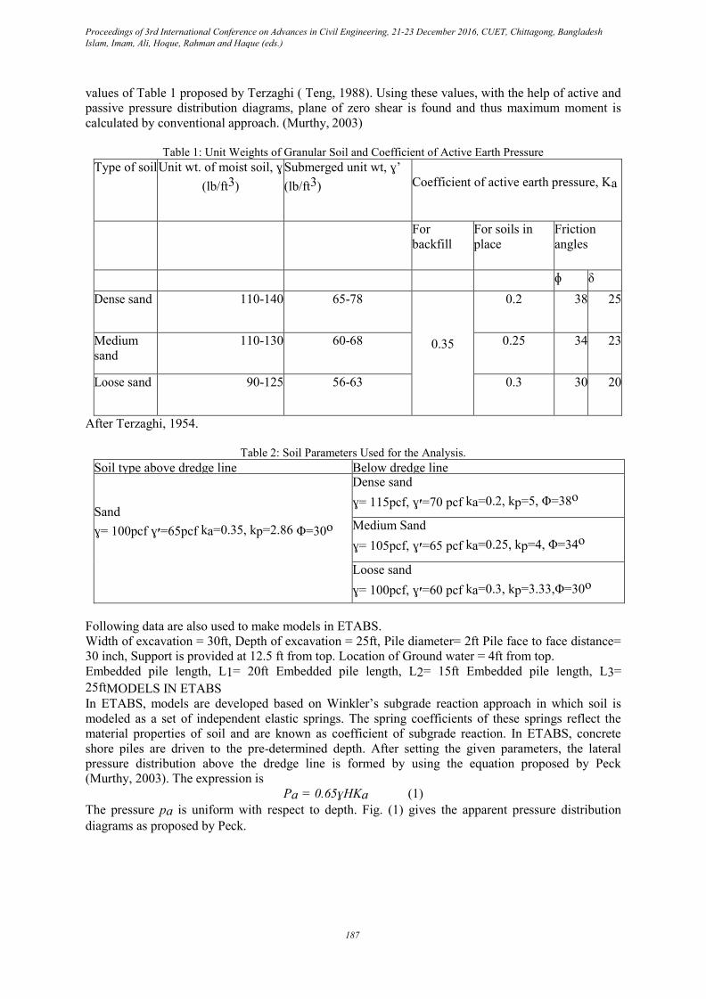
The pressure pa is uniform with respect to depth. Fig. (1) gives the apparent pressure distribution
diagrams as proposed by Peck.
Proceedings of 3rd International Conference on Advances in Civil Engineering, 21-23 December 2016, CUET, Chittagong, Bangladesh Islam, Imam, Ali, Hoque, Rahman and Haque (eds.)
187
Fig. 1: Earth Pressure Distribution Diagrams for Braced Cuts (Peck, 1974)
Below the dredge line, Winkler’s subgrade reaction concept is used. Springs are placed at one feet
depth down to the depth of embedment. For sandy soil the coefficient of horizontal subgrade reaction
is computed fromk= nh
(2)
Where nh= coefficient of horizontal subgrade reaction for a one feet wide pile at one feet depth. Z=
depth in ft, B= width of pile in ft.
The values of nh are used from a Table 2 given by Terzaghi. (Bowles, 1997)
Table 2: Values of Coefficient of Horizontal Subgrade Reaction (lb/in3) for a one Feet Wide Pile at one Feet
Depth Given By Terzaghi
Loose sand Medium sand Dense sand
Dry or moist 8 24 65
Submerged 4 16 40
The values of coefficient of horizontal subgrade reaction thus computed are put in each feet depth
down to the bottom. For each nh values, separate models are developed and analysis is run on ETABS
and thus maximum moments and corresponding deflections for a particular soil profile and loading
conditions are obtained before and after providing supports. Analysis is also carried out in a similar
way by changing the depth of embedment of pile.
LOAD CALCULATION
Pa = 0.65ɣHKa = 0.65*0.35*70.6*25= 0.4ksf
Considering each pile takes load from each side.
Load per ft of depth= 0.40*(pile diameter + pile face to face distance)
= 0.40*(2+0.5) = 1k/ft
This load and corresponding moments and lateral displacements are for 2.5 ft width. Coefficient of
subgrade reaction, ks= nhz/B*1ft* pile diameter (k/ft)
This values obtained are placed after 1ft depth successively.RESULTS AND DISCUSSIONS
Proceedings of 3rd International Conference on Advances in Civil Engineering, 21-23 December 2016, CUET, Chittagong, Bangladesh Islam, Imam, Ali, Hoque, Rahman and Haque (eds.)
188

(a) (b)
Fig. 2: (a) Moment vs Length graph (b) Lateral Displacement vs Length graph in unsupported state for different
n values
In this research, variations of moments and lateral displacements with length of pile for different n
values are observed. In unsupported state, for a fixed embedded length of pile, from Fig.2 (a), the
values of maximum moment are found to be 376.4 k-ft, 386.2 k-ft and 401.09 k-ft respectively and
maximum lateral displacements are found to be 5.5 inch, 7.19 inch and 14.2 inch respectively from
Fig.2 (b) for corresponding modulus of subgrade reaction values of 40lb/in3, 16lb/in3 and 4 lb/in3 as
proposed by Terzaghi (Teng, 1998). As can be seen from figure, up to dredge line the values of
moment are same for different n values but after dredge line the curve splits as per n value. For lower
n value moments are larger. As modulus of subgrade reaction represents the stiffness of the soils,
greater values of it will yield comparatively less moment and deflection. Moreover, moment values
are larger for loose sand, then for medium sand followed by dense sand in unsupported condition
which is satisfactory. Moment values are also close to each other. In unsupported condition, deflection
increases with length and becomes maximum at the top of the pile. The lateral displacement is quite
higher for loose sand in comparison with medium and dense sand.
(c) (d) Fig. 3: (c) Moment vs Length graph (d) Lateral Displacement vs Length graph in supported state for different n
values
Afterwards, a support is provided at 12.5 ft from top and in this state, for subgrade reaction values
40lb/in3, 16lb/in3 and 4 lb/in3, values of maximum moment are observed as 78.12 k-ft. 78.13 k- ft,
78.13 k-ft in Fig. 3(c) and maximum lateral deflections are reduced and found as 0.15 inch for
each type of soil in Fig. 3(d). It is clear that after providing support lateral displacements and
moments are reduced and assume very close values for dense, medium and loose sand as per n
values.
Proceedings of 3rd International Conference on Advances in Civil Engineering, 21-23 December 2016, CUET, Chittagong, Bangladesh Islam, Imam, Ali, Hoque, Rahman and Haque (eds.)
189

(e) (f)
Fig. 4: (e) Moment vs Length graph (f) Lateral Displacement vs Length graph for varying embedded lengths
Again, for a fixed n value embedded length is changed (15ft, 20ft and 25ft) and the variations in
moments and lateral displacements are also observed. Figures above are drawn for the same n value
40lb/in3 and it is seen that the more the embedded length of pile is, the more the resisting moment is
and also larger embedded length results in lower value of lateral displacement. For other n values,
similar types of results are obtained.
These signs and magnitudes of the parameters are according to expectations.
CONCLUSION
This research was conducted to study the variations in moments and lateral displacements of shore
pile with varying embedded lengths in supported and unsupported conditions using Subgrade
Reaction approach of modeling soil behavior. From the developed models, one can readily find out
the moments and lateral displacements of each point on the shore pile for the given loading
conditions and soil profiles and thus providing lateral support at a suitable position, entire lateral
support system can be designed by ETABS.
For different soil profiles, lateral displacements due to earth pressure can be reduced by providing
supports or by increasing the embedded pile length. Lateral supports also reduce the embedded pile
length. However, the models are developed only for granular soils which can be extended further to
study the cohesive and layered type of soils as well.
REFERENCES
Teng, WC. 1988. Foundation Design. London: Prentice Hall International. 356p.
Bowles, JE. 1996. Foundation Analysis and Design. New York: McGraw-Hill, 505p & pp. 791-800.
Murthy, VNS. 2003. Principles and Practices of Soil Mechanics and Foundation Engineering. New
York: Marcel Dekker,906-913.
Macnab, A. 2002. Earth Retention Systems Handbook. New York: McGraw-Hill, pp. 319-322.
Broms, BB. 1964b. Lateral Resistance of Piles in Cohesionless Soils. Journal of the Soil Mechanics
and Foundation Division, American Society of Civil Engineers, 90( SM3):123-156.
Proceedings of 3rd International Conference on Advances in Civil Engineering, 21-23 December 2016, CUET, Chittagong, Bangladesh Islam, Imam, Ali, Hoque, Rahman and Haque (eds.)
190