Embed Size (px)
Citation preview
ANALYSIS OF SOIL NAILED WALLS UNDER SEISMIC EXCITATIONS USING FINITE DIFFERENCE METHOD
A. M. Halabian1 , A. M. Sheikhbahaei2 and S. H. Hashemolhosseini3
ABSTRACT Soil nailing is an efficient method to stabilize various soil structures. The method has
been extensively used for improving stability of slopes. The construction process of Soil nailed walls commonly involve three basic steps: excavation, nail installation and face stabilization. The nails are inserted into ground by either drilling or grouting and are usually arranged in both horizontal and vertical directions. Present research intends to understand soil-nailed walls behavior under dynamic excitations. Employing finite difference method, a three dimensional model has been developed in a proper finite difference code. Soil constitutive behavior for dynamic analyses is predicted taking into account soil hysteresis behavior. To simulate nails cable structural elements are employed and liner structural elements are also utilized for shotcrete facing. Earthquake excitation as dynamic loading is applied at the bottom of model where represents soil subgrade. Having absorbing boundaries used, the boundary conditions are considered to be antisymmetric during dynamic analyses. Effects of different crucial factors are monitored during investigations. Some parameters such as loading frequency content, soil constitutive behavior and soil strength properties have been examined.
Introduction The soil-nailed wall technique is typically used in order to stabilize slopes and excavations where sequential construction is beneficial in comparison with other common gravity and retaining walls. The fundamental stability concept of soil-nailed walls is based on reinforcing soil mass with reinforcement elements such as steel rebars so that the soil mass would behave as a unit mass. Due to significant flexibility of soil-nailed walls which is attributed to particular construction procedure of these systems, soil nailed walls can experience more deflections comparing with other common gravity walls. After the 1989 Loma Prieta, 1995 Kobe and 2001 Nisqually earthquakes, it was reportedly observed that soil nailed walls have shown no sign of being distressed or significant permanent deflection, despite having experienced, in some cases, ground accelerations as high as 0.7g. The observations from post-earthquake investigations imply that soil-nailed walls appear to have an inherent satisfactory seismic response. This has been attributed to the intrinsic flexibility of soil-nailed wall system and possibly some level of conservatism in current design procedures (Choukeir et al. (1997)). As a result, these systems are definitely appropriate choice for many geotechnical engineering purposes. Slope stability analyses based on limit-force equilibrium methods have been developed to assess the global stability of soil-nailed walls together with local stability of reinforced soil 1 Professor, Dept. of Civil Engineering, Isfahan University of Technology, Isfahan, Iran 2Graduate Research Assistant, Dept. of Civil Engineering, Isfahan University of Technology, Isfahan, Iran 3 Professor, Dept. of Mining Engineering, Isfahan University of Technology, Isfahan, Iran
Proceedings of the 9th U.S. National and 10th Canadian Conference on Earthquake Engineering Compte Rendu de la 9ième Conférence Nationale Américaine et 10ième Conférence Canadienne de Génie Parasismique July 25-29, 2010, Toronto, Ontario, Canada • Paper No 1350

mass by taking into account different factors influencing wall performance, i.e. shearing, tension and pull-out resistance of the inclusions. One of the most common methods used to analyze soil-nailed walls is pseudo-static approach by which dynamic earth pressure is computed using conventional Mononobe-Okabe (Prakash 1981) or a modified two-part wedge method, Matuso and Okabe modified Coulomb’s solution, to account for inertia forces corresponding to the estimated earthquake induced horizontal accelerations. Despite the fact that limit equilibrium methods provide satisfactory information about both overall and internal stability of the structure, they cannot succeed to provide any information regarding mobilized forces along nails as well as deformations of the structure. Therefore, due to the fact that these approaches are not sufficient to predict wall behavior, numerical methods have been employed in order to have better understanding of wall performance under both static and dynamic loading conditions. Nevertheless there are a few studies concerning dynamic behavior of the soil-nailed walls. Seed et al. (1975) conducted finite element analyses to examine seismic response of reinforced earth retaining walls. They considered an inertia force for the potential active zone which is in proportion with the weight of the active zone. Finally, the proposed method by these investigators incorporated in the FHWA (2003) design guidelines for reinforced soil systems. Dhouib developed a non-linear finite element code to model reinforced soil walls subjected to dynamic loading (Choukeir et al. (1997)). The results of investigations indicated that the incremental dynamic force is proportional to the distribution of static forces and the geometry of the active zone under dynamic loading is a function of the earthquake acceleration. Segrestin and Bastick (1988) conducted finite element analyses to understand seismic response of soil-reinforced structures. In their studies the elastoplastic behavior of the soil was simulated by varying the modulus of elasticity as a function of observed deformations. The results of study indicate that the distribution of dynamic tensile forces along the strips is fairly uniform and does not give significant change in the position of points of maximum tension. Sabahit et al. (1996) presented a new pseudo-dynamic method to analyze soil-nailed slopes (Choukeir et al. (1997)). By Assuming constant shear modulus and limited shear wave velocity in addition to varying earthquake acceleration along wall depth, they obtained the total required reinforcement forces. The present paper aims to focus on the seismic behavior of the soil-nailed retaining structures due to earthquakes. The method used to undertake the research is numerical finite difference method. Therefore, a 3D finite difference mesh has been developed representing soil medium, along with cable and liner elements to simulate nails and shotcrete facing. Having better perception of soil behavior under seismic excitations a nonlinear hysteretic soil constitutive model was employed. Moreover, the paper outlines the interaction mechanism between different components of soil-nailed walls along with soil constitutive model. In conclusion, a comprehensive parametric study has been conducted examining effects of crucial parameters on performance of these structures under seismic loading situations.
Numerical simulation The present research seeks to have better understanding of seismic response of soil-nailed structures. Therefore, a 3-D model has been developed to gain better perception of soil-nailed structures behavior taking into account the wall construction stages which includes nail installation and application of shotcrete facing. The finite difference mesh used for analyses is illustrated in Fig. 1-a. This mesh employed for analyses is made up of quadrilateral continuum
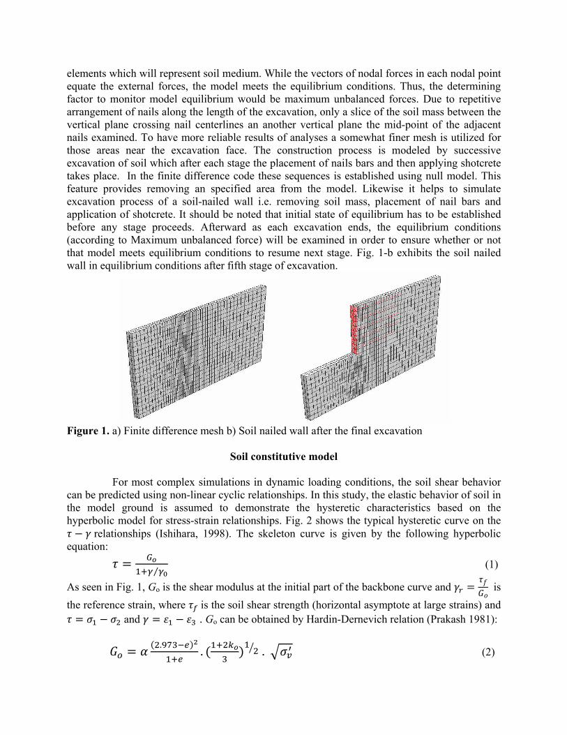
elements which will represent soil medium. While the vectors of nodal forces in each nodal point equate the external forces, the model meets the equilibrium conditions. Thus, the determining factor to monitor model equilibrium would be maximum unbalanced forces. Due to repetitive arrangement of nails along the length of the excavation, only a slice of the soil mass between the vertical plane crossing nail centerlines an another vertical plane the mid-point of the adjacent nails examined. To have more reliable results of analyses a somewhat finer mesh is utilized for those areas near the excavation face. The construction process is modeled by successive excavation of soil which after each stage the placement of nails bars and then applying shotcrete takes place. In the finite difference code these sequences is established using null model. This feature provides removing an specified area from the model. Likewise it helps to simulate excavation process of a soil-nailed wall i.e. removing soil mass, placement of nail bars and application of shotcrete. It should be noted that initial state of equilibrium has to be established before any stage proceeds. Afterward as each excavation ends, the equilibrium conditions (according to Maximum unbalanced force) will be examined in order to ensure whether or not that model meets equilibrium conditions to resume next stage. Fig. 1-b exhibits the soil nailed wall in equilibrium conditions after fifth stage of excavation.
Figure 1. a) Finite difference mesh b) Soil nailed wall after the final excavation
Soil constitutive model
For most complex simulations in dynamic loading conditions, the soil shear behavior can be predicted using non-linear cyclic relationships. In this study, the elastic behavior of soil in the model ground is assumed to demonstrate the hysteretic characteristics based on the hyperbolic model for stress-strain relationships. Fig. 2 shows the typical hysteretic curve on the relationships (Ishihara, 1998). The skeleton curve is given by the following hyperbolic equation: ⁄ (1)
As seen in Fig. 1, Go is the shear modulus at the initial part of the backbone curve and is the reference strain, where is the soil shear strength (horizontal asymptote at large strains) and
and . Go can be obtained by Hardin-Dernevich relation (Prakash 1981): . . . (2)

in which e , , Ko are void ratio, effective vertical stress and confining pressure ratio, respectively.
Fig.2 - Soil stress-strain relationship
The sign of the increment, d , judges the reversal of loading direction. For each loading-reloading loop, after reversal point, the unloading path is defined as (3) in which and are the shear stress and shear strain at the reversal point. In the hyperbolic model the tangent shear modulus of elasticity for loading and reloading can be obtained from
⁄ | | ⁄ | | (4)
In this study, an energy dissipation approach was used to predict the reversal point in loading-reloading paths of hysteretic loop. Based on this approach (Halabian et al. 2008) the reversal loading direction is judged by the sign of the dissipated energy increment (the incremental shear work), WS. The shear work increment can be obtained in a FEM analysis as the different between the total incremental work, WT, and the incremental volumetric work, WN, for an increment strain during loading or reloading as Δ Δ Δ (5) where Δ Δ Δ Δ 2 Δ Δ Δ Δ . ∑ Δ (6) The rebound shear modulus can be calculated by effective stresses through a non-linear dynamic analysis. This basic model can produce curves of apparent damping and modulus versus cyclic strain that resemble results from laboratory tests. In the plastic zone the Mohr-Coulomb failure constitutive model was adopted where the failure envelope corresponds to Mohr-Coulomb criteria.
Soil-nailed wall modeling and governing equations Cable structural elements were employed to simulate soil nails. A one-dimensional constitutive model is adequate for describing the axial behavior of the reinforcing member. The axial stiffness K is determined based on the reinforcement cross-sectional area A, Young’s modulus E and cable structural element length L by the relation K=EA/L. A tensile and

compressive-yield strength, Ft and Fc, may be assigned to each cable structural element such that cable forces cannot develop that are greater than these limits. According to a pull-out test results the nail parameters given in Table 1 are assumed in the following analyses. The shear behavior of cable-soil interface is naturally cohesive and frictional. This system is represented as a spring-slider system which is placed at each nodal point along the cable axis (Fig. 3(a)). The shear behavior of the grout annulus, during relative shear displacement between the cable/grout interface and the grout/soil interface, as illustrated in Fig. 3(b) , is described numerically by the grout shear stiffness kg, the grout cohesive strength cg, the grout friction angle φg, the grout exposed perimeter pg, and the effective confining stress σm.
Table 1. Properties of nail in FDM analyses
Nail Characteristics
200 460 7800 9 0.025
Figure 3. a) Mechanical representation of fully bonded reinforcement b) Idealization of grouted-cable system Liner Structural Elements has also been incorporated to represent shotcrete made wall facing of soil-nailed walls. The properties of the facing wall were assigned the following values: Elastic Modulus, 25 ; Poisson’s ratio, 0.2; Unit weight, 24 / . The interface behavior is represented numerically at each liner node by a linear spring with finite tensile strength in the normal direction and a spring-slider in the tangent plane to the liner surface. As it was mentioned previously, the finite difference method was employed to solve the equations of motions. Thereby, mechanics of each continuum can be derived from main principles, i.e. definition of strain motion, motion laws together with constitutive equations defining the material as an idealized system. Equations of motion on an unbounded medium is expressed as following: σ , ρb ρ i, j 1,2,3 (8)
where is the mass per unit volume of the medium , b is the body force per unit mass, and is the material derivative of the velocity. In the Finite difference method, these governing equations represent the motion of an elementary volume of the medium subjected to the forces. Constitutive law usually comes in form of following equation: , , (9)
Soil
Grout
Cable

which is the co-rotational stress-rate tensor is the given function related to Mohr-Coulomb yield criterion, κ is a parameter which takes into account the history of loading, while is a strain rate tensor. To solve the governing equations, an explicit “time-marching” finite difference solution scheme is used.
Numerical analyses The comparisons between the numerical results of the developed numerical 3D FD model described above and the data from experiments performed by Hong et al. (2005) are carried out first to verify the applicability of 3D modelling of soil-nailed walls under dynamic excitations. The experimental study by Hong et al. (2005) was conducted on a scaled soil-nailed wall model excited by a shaking table device. The model geometries and properties were obtained using similarity analyses performed on the prototype sample. Figs. 4 shows the photo of the tested soil-nailed wall model along with the model dimensions and installed instrumentation. For the Chi-Chi ground motion, the absolute displacement time histories of the experimental model and the numerical calculations obtained using the developed model in this study are shown in Figs. 5 and 6, respectively. The time histories in these figures show reasonably good agreement. Nevertheless, certain discrepancies during the process of time history responses are may be due to the nature of nailing technique.
Figure 4. The tested scaled soil-nailed wall model
-2
-1
0
1
2
3
4
5
0 2 4 6 8 10 12 14 16 18Time (s)
Dis
plac
emen
t (m
m)
Figure 5. Horizontal displacement Time histories obtained from numerical analysis
Figure 6. Horizontal displacement Time histories obtained from experiments
Having the presented 3D modeling technique verified, to get better understanding of

affecting parameters on seismic response of soil-nailed wall systems, a parametric study was conducted hereafter. The soil properties for model used in this study are selected based on assuming that a resonance situation is going to be established in the soil layer. Considering this, the soil natural frequency is supposed to be equal to that of input motion resulting in a resonance situation in that layer. The horizontal base reference acceleration time histories of the 1940 El Centro, the 1995 Kobe and the 1994 Northridge earthquakes were considered in the dynamic analyses. Only the first 30 seconds of the earthquake were considered and the remainder of this duration was deemed insignificant. It is noteworthy that the El Centro earthquake was used herein for its mild peak acceleration of approximately 0.30g, whereas the Northridge earthquake was incorporated in the seismic analyses of soil-nailed walls due to its high peak amplitude of acceleration. Spectrum analysis of the input acceleration reveals a predominant frequency of 1.8 Hz, 1.4 Hz and 3 Hz for El Centro, Kobe and Northridge earthquake motions, respectively. Having the predominant frequencies of the seismic excitations evaluated, with regard to the soil layer depth the soil shear velocity will be acquired. Along with soil shear velocity, other soil characteristics such as shear modulus can be determined. However, it is worth mentioning that for simplicity the soil parameters were held constant during dynamic analyses. The parameters used for soil characteristics in different input motions are presented in Table 2. At the end of excavation, after static equilibrium is achieved in the numerical model, the full width of soil subgrade is subjected to seismic excitations assumed in this study. In the developed 3D models, anti-symmetric boundary conditions were used in order to undertake
Table 2. Soil Characteristics used for dynamic analyses
dynamic analyses. Having better simulation of boundaries during numerical dynamic analyses, the boundary conditions at the sides of the model must account for the free-field motion that would exist in the absence of the structure. Therefore, a Free-field boundary conditions were used at the left and right edges of the model to permit for the radiation of the elastic waves to the far field. The base condition is freed in the horizontal direction while the soil subgrade is subjected to horizontal seismic excitations. Present work has studied effects of numerous parameters contributing on performance of soil-nailed walls during seismic excitations such as nonlinear soil constitutive behavior, excitation frequency content and soil strength parameters. Soil non-linear behavior Using non-linear cyclic relationships is expected to be an appropriate choice to predict soil behavior under dynamic loading situations. Present study has intended to understand whether or not soil nonlinearity would have significant changes on response of soil nailed
Soil Characteristics Soil
Density (kg/m3)
Friction Angle
o
Cohesion c (kPa)
ν
Predominant Frequency
f
Dilation Angle
Shear Modulus
Gmax
Shear Velocity
Vs Earthquake
El-Centro 1800 28 5 0.25 1.8 2 30.23 129.6
Kobe 1800 28 5 0.25 1.4 2 100.8 18.3
Northridge 2000 28 5 0.25 3 2 93.31 216

structures. The horizontal displacement response at the wall head during base acceleration of El Centro earthquake reveals the fact the soil hysteresis behavior might be able to better predict soil behavior under complex situations of dynamic loading. As a result, the displacement response at wall head has shown a diminishing response during base excitation period in comparison with similar walls using equivalent linear model (Fig. 7). Figs. 8 and 9 display normalized peak acceleration and displacement response at the selected locations along the wall facing. The data show that peak acceleration and displacement profiles decrease as the soil behavior under seismic loading conditions is predicted using a nonlinear hysteresis model behavior.
Figure 7. Horizontal displacement response time history at the wall head during base excitation
(El Centro earthquake)
Figure 8. Normalized peak horizontal displacement distribution along height of wall facing
Figure 9. Peak horizontal acceleration distribution profile along height of wall facing
Base Excitation The earthquake motions have substantial influence on deformations of soil-nailed walls. In the present study three base excitation records of El Centro, Kobe and Northridge earthquakes with peak amplitude accelerations of 0.3g, 0.61g and 1.78g were considered. As a consequence of analyses observations, it was observed that Northridge earthquake motion induced considerable lateral displacements whereas the peak magnitude of lateral displacement along wall facing subjected to base excitation of El Centro earthquake would be only 15% of that of
-0.08
-0.06
-0.04
-0.02
0
0.02
0 5 10 15 20 25 30
Hor
izon
tal D
ispl
acem
ent (
m)
Time (s)
Hysteresis ModelLinear Model
0
0.25
0.5
0.75
10 0.2 0.4 0.6 0.8
d / H
Normalized Peak Horizontal Displacement (%)
Hysteresis ModelLinear Model
0
0.25
0.5
0.75
10 2 4 6 8
d / H
Peak horizontal acceleraction (m/s2)
Hysteresis ModelLinear Model
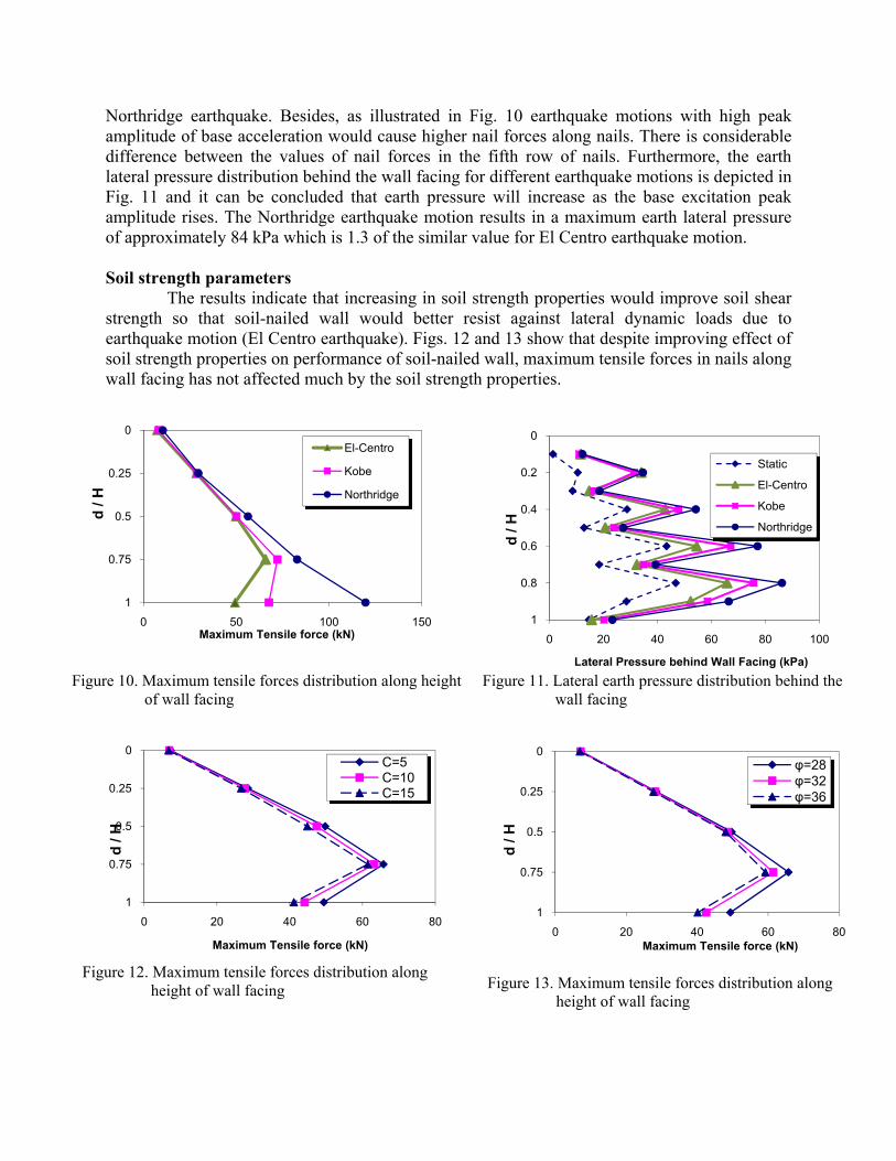
Northridge earthquake. Besides, as illustrated in Fig. 10 earthquake motions with high peak amplitude of base acceleration would cause higher nail forces along nails. There is considerable difference between the values of nail forces in the fifth row of nails. Furthermore, the earth lateral pressure distribution behind the wall facing for different earthquake motions is depicted in Fig. 11 and it can be concluded that earth pressure will increase as the base excitation peak amplitude rises. The Northridge earthquake motion results in a maximum earth lateral pressure of approximately 84 kPa which is 1.3 of the similar value for El Centro earthquake motion. Soil strength parameters The results indicate that increasing in soil strength properties would improve soil shear strength so that soil-nailed wall would better resist against lateral dynamic loads due to earthquake motion (El Centro earthquake). Figs. 12 and 13 show that despite improving effect of soil strength properties on performance of soil-nailed wall, maximum tensile forces in nails along wall facing has not affected much by the soil strength properties.
Figure 10. Maximum tensile forces distribution along height of wall facing
Figure 11. Lateral earth pressure distribution behind the wall facing
Figure 12. Maximum tensile forces distribution along height of wall facing
Figure 13. Maximum tensile forces distribution along height of wall facing
0
0.25
0.5
0.75
10 50 100 150
d / H
Maximum Tensile force (kN)
El-Centro
Kobe
Northridge
0
0.2
0.4
0.6
0.8
10 20 40 60 80 100
d / H
Lateral Pressure behind Wall Facing (kPa)
Static
El-Centro
Kobe
Northridge
0
0.25
0.5
0.75
10 20 40 60 80
d / H
Maximum Tensile force (kN)
C=5C=10C=15
0
0.25
0.5
0.75
10 20 40 60 80
d / H
Maximum Tensile force (kN)
φ=28φ=32φ=36
Conclusions A 3-D FD model was developed to examine the seismic behavior of soil-nailed walls. The information obtained from the analyses of the soil-nailed walls models used in this study contributes to have a better perception of dynamic performance of these structures. In order to validate the proposed model, the measurements of a scaled soil-nailed wall model subjected to a simulated earthquake excitation were compared to the numerical response. Conclusion of the work described in this paper focused on effect of soil non-linear hysteretic behavior, base excitation frequency content and soil strength parameters. The results showed that the dynamic earth pressure distribution behind the wall is almost following the static distribution but with different order. However, the trend shows much different soil distribution compared to well-known earth pressure relations such as Peck. To reach a suggested dynamic soil pressure scheme for soil-nailed walls more computational effort is needed. Enhancing the soil strength properties would improve soil shear strength so that soil-nailed wall would better resist against dynamic loads due to seismic base excitation.
References Choukeir, M., I. Juran, and S. Hanna, 1997. Seismic design of reinforced-earth and soil-nailed structures, Ground Improvement 1, 223- 238. Federal Highway Administration (FHWA) 2003. Geotechnical Engineering Circular No. 7, Soil Nailed Walls, Report No. FHWA0-IF-03-017. (Carlos A. Lazarte, Victor Elias, R. David Espinoza, Paul J. Sabatini) Washington, DC., USA. Halabian, A. M., S. H. Hashemolhosseini, and H. Saldourgar, 2008. Seismic response of structures with underground stories considering nonlinear soil-structure interaction, Proc. 6th international conference on Case Histories in Geotechnical Engineering, Arlingtion, VA. Hong, Y. S., R. H. Chen, C. S. Wu, and J. R. Chen, 2005. Shaking table tests and stability analysis of steep soil nailed slopes, Canadian Geotechnical Journal 42, 1264-1279. Ishihara, K., 1996. Soil Behavior in Earthquake Engineering, Clarendon Press, Oxford University, New York, USA. Prakash, S., 1981. Soil Dynamics, McGraw-Hill, Inc. Seed, H. B., P. P. Martin, and J. Lysmer, 1975. The Generation and Dissipation of Pore Water Pressures During Soil Liquefaction, Earthquake Engineering Research Center, UC-Berkeley NSF Report PB-252 648. Segrestin, P., and M. J. Bastick, 1988. Seismic design of reinforced earth retaining walls. Proc. International Geotechnical Symposium on Theory and Practice of Earth Reinforcement, Fukuok Kyushu, Japan, 577–582.