Embed Size (px)
Citation preview

Journal of Civil, Construction and Environmental Engineering 2017; 2(4): 100-111
http://www.sciencepublishinggroup.com/j/jccee
doi: 10.11648/j.jccee.20170204.11
Analysis of Stress- Strain and Deflection of Flexible Pavements Using Finite Element Method Case Study on Bako-Nekemte Road
Shiferaw Garoma Wayessa1, Emer Tucay Quezon
2, Tarekegn Kumela
2
1School of Civil and Environmental Engineering, Jimma Institute of Technology, Jimma University, Jimma, Ethiopia 2Construction and Engineering Management Stream, School of Civil and Environmental Engineering, Jimma Institute of Technology, Jimma
University, Jimma, Ethiopia
Email address: [email protected] (S. G. Wayessa), [email protected] (E. T. Quezon), [email protected] (E. T. Quezon),
[email protected] (T. Kumela)
To cite this article: Shiferaw Garoma Wayessa, Emer Tucay Quezon, Tarekegn Kumela. Analysis of Stress- Strain and Deflection of Flexible Pavements Using
Finite Element Method Case Study on Bako-Nekemte Road. Journal of Civil, Construction and Environmental Engineering.
Vol. 2, No. 4, 2017, pp. 100-111. doi: 10.11648/j.jccee.20170204.11
Received: June 19, 2017; Accepted: June 30, 2017; Published: September 7, 2017
Abstract: In Ethiopia the failure of roads are before handover period. Most roads found in Ethiopia are flexible pavements.
Nowadays, the failure of surface of flexible pavement roads are common before the expected design period. For the example
Bako-Nekemte road/ has become a critical issue in our country. The most common parameters that cause stress, strain and
deflection of the roads are loads and pressures that come from vehicles. Moreover, modulus of elasticity, Poisson’s ratio and
thickness of each layer needs to be characterized. Further, the load magnitude, contact pressure (or load radius) and location are
defined for each load (wheel) considered. Finite element method (FEM) is a numerical analysis technique to obtain the
stress-strain and deflection of each pavement layers. Analytical method usually uses layers thickness, loads, elastic modulus and
Poisson’s ratio of the pavement materials as design parameters. The objective of this research was to study the sensitivity of the
road parameters in analyzing the major causes of failure in asphalt pavement layers fatigue cracking and rutting deformation
which came due to the critical tensile strains at the bottom of the asphalt layer and the critical compressive strains on the top of
subgrade using the finite element method by relating the standard specification of ERA and laboratory test result. This thesis
studied the analysis of stress-strain and deflection of flexible pavements using Everstress finite element method. The Ever stress
program will take into account any stress dependent stiffness characteristics. This thesis dealt with ways to reduce deflections by
varying the design configuration, such as increasing the HMA modulus, the base modulus, sub base modulus, the subgrade
modulus and increasing thickness of each layers. Based on type of materials to use the value of elastic modulus and poison’s ratio
are various in each layers, in layer 1 is varied from 1500 to 3500 MPa, in layer 2 is varied from 200 to 1000MPa, in layer 3 is
varied from 100 to 250 MPa and in layer 4 is varied from 20MPa to 150MPa.
Keywords: Finite Element Analysis, Flexible Pavement, Layers Thickness, Modulus and Vertical Surface Deflections
1. Introduction
Nowadays the number and type of traffic increases from
day to day at global level. In developing countries like
Ethiopia, the traffic changes from time to time. This enforces
to develop the construction of road infrastructures, which
needs economical and safe design of roads. The most common
type of pavement used in Ethiopia is flexible pavement. A
flexible pavement is one that has low flexural strength and
transmit load to subgrade soil through lateral distribution of
stress with increasing depth. Deformation of subgrade soil is
the factor that affects the strength and smoothness of flexible
pavement.
The aim of this paper was to study the sensitivity of the road
parameters (dimension, layers thickness, elastic modulus,
Poisson’s ratio, loads and pressures). To control the vertical
surface deflections which caused the critical tensile strains at
the bottom of the asphalt layer and the critical compressive
strains on the top of subgrade using the finite element method
by relating the standard specification of road condition from

101 Shiferaw Garoma Wayessa et al.: Analysis of Stress- Strain and Deflection of Flexible Pavements Using Finite
Element Method Case Study on Bako-Nekemte Road
the existing documented data. These variables can use to
improve pavement performance.
1.1. Statement of the Problem
Road surface failure is a critical issue on the flexible
pavement where it involves a very high maintenance cost
every year. One of the reasons causing these failures are
fatigue cracking and rutting deformation due to improper or
error of pavement elastic modulus and layers thickness design.
The most common causes of fatigue cracking and rutting
deflection are due to stress or strain. Most of the flexible
pavement roads in our country are begun to failure before
expected period. The road from Bako-Nekemte is constructed
before four years ago that is until now not handover but it is
started to deteriorate.
In our country, it is not common to use software based
design of flexible pavements rather than the design agencies
practice the method by referring the hardcopy of design
guideline manual (AASHTO and ERA) and calculation.
Mistakes are mostly occurred or error cannot be fully avoided
in the design that influences the quality of the design and
development of the science. Manual design method has a
problem in doing many alternatives for comparison as flexible
pavement design involves different nomograph, charts, tables
and formulas. Therefore, it was complex and time taking
practice which may result in unsafe or uneconomical design.
The use of FEM model through Everstress allows the model
to accommodate the load dependent stiffness of the road
layers, granular and subgrade materials which most of the
models still use linear elastic theory as constitutive
relationship. The load come from vehicles must be distributed
properly otherwise it-enforced deflection of the road.
1.2. Research Questions
a) What are the parameters that cause stress-strain and
deflection of flexible pavement?
b) How stress-strain and deflection of flexible pavement
materials are analyzed using Ever Stress Finite Element
software by using laboratory test result and ERA
standard specification?
c) How the layers of flexible pavement are affected by
vertical surface deflections and the critical horizontal
tensile strains?
1.3. Objective of the Study
1.3.1. General Objective of Study
The general objective of this study is analysis of
stress-strain and deflection of flexible pavements using finite
element method software case study on Bako-Nekemte road.
1.3.2. Specific Objectives of the Study
a) To identify the parameters that causes stress, strain and
deflection of flexible pavement.
b) To analyze the stress, strain and deflection of flexible
pavement using finite element method software by using
the laboratory test result and ERA standard specification.
c) To describe how the layers of flexible pavement are
affected by vertical surface deflections and the critical
horizontal tensile strains.
2. Research Methodology
Finite element method (FEM) is a numerical analysis
technique to obtain the stress-strain and deflection of each
pavement layers.
2.1. Study Area
The study is carried out on the Bako-Nekemte road found in
the eastern Wollega districts of the Oromia Regional State.
The area exhibit moderate to cold climate conditions and
connects the town such as Bako, Ano, Sire, Cheri, Jalele,
Chingi, Gaba Jimata, Gute and Nekemte.
Figure 1. Map of the research study area.
2.2. Design Method of the Study
It is similarly analytical because it systematically identifies
numerical analysis and addresses the practical cause, problem,
and their solution. Analytical method usually uses layers
thickness, loads, elastic modulus and Poisson’s ratio of the

Journal of Civil, Construction and Environmental Engineering 2017; 2(4): 100-111 102
pavement materials as design parameters.
2.3. Assumptions of Analytical Solutions to the State of
Stress or Strain
a) The material properties of each layer are homogenous &
Each layer has finite thickness except for the lower layer
b) All layers are infinite in lateral directions
c) Each layer is isotropic (having the same magnitude or
properties when measured in different direction).
d) Full friction is developed between layers at each
interface
e) The stress solution are characterized by two material
properties for each layer (E & υ)
2.4. Basic Component of Layers in Bako-Nekemte Road
Bako–Nekemte asphalt concrete consist the following
component of layers, which is different thickness. The
thickness of each layers are the same throughout
Bako-Nekemte road except at some places where there is
capping layers where California bearing ratio is less than
fifteen. The components are surface course, base course, sub
base course, and subgrade course. (Source: Bako-Nekemte
road upgrade document)
Figure 2. Basic Component of layers in Bako-Nekemte road.
2.5. Type of Soil Through Studying Area
According the observations made on the natural soil surface
and on exposed soils of cut slopes as well as investigations and
laboratory testing result for sub-grade and materials study, the
predominant soil type along the Bako - Nekemte road is
well-drained reddish to brown clay with short sections of black
cotton soil at and near river crossings. Most of the soils along the
roadside appear suitable for the use in the proposed road
construction works. Generally, Bako-Nekemte soil properties are
good for construction of the road except around river and stream.
2.6. Characteristics of Climate Through Studying Area
The climate in the project area can be described as
temperate in general. The project road runs through one of the
highest rainfall areas in the country with a mean annual
rainfall ranging from 1,200 to 2,000 mm. Rainfall in the
project area has a typical uni-modal characteristics with the
rainy season extending from May to October.
During the rainy season, May to October, ITCZ is
positioned to the north of the project area and during the dry
season, its position is in the south.
2.7. Sampling Procedure
The definition of targeting population has been in line with
the objectives of the analysis of stress-strain and deflection of
flexible pavements using finite element method. A sampling
frame would be from the laboratory test result.
2.8. Sampling Technique of Research Study
The sample inspections selected may be provided by an
estimate of the analysis of stress- strain and deflection of
flexible pavements. By using the sampling technique to
collect data from site (distress area), depend on the mean
severe area, laboratory result, standard of specification of
AASHTO or ERA, and laboratory staffs who know property
of materials of the road. These collected data are input data,
the output will be analyzed using ever stress software.
2.9. Data Processing and Analysis
After successful collection of data has been arranged, then
data collected according the context of the research and
analysis the data using the pavement software, Microsoft
excel and other road tools. From the result, we analyzed all the
factors affecting flexible pavement road, then evaluate the
factors according to their magnitude of their effect and
according to their urgency. The collected data from the study
area (road condition survey, distress area), laboratory result
and standard specification of AASHTO and ERA were
analyzed and interpreted to charts, graphs, figures and tabular
formats using excel and other road tools to evaluate the major
factors affecting flexible pavement road problem on which
needs engineering and scientific solutions. Everstress or
Everseries is a free program that was developed by the
Washington State. Department of Transportation for paving
design purposes. The program can analyze a pavement
containing up to five layers (this study uses four) and its
primary purpose is to estimate stress, strain and deflection
within a layered pavement system due to a static load or loads.
2.10. Elastic Modulus of road Component
The flexible pavement road of Bako- Nekemte has four
layers component which were surface layer, base layers,
subbase layer and subgrade layer. It is difficult to get elastic
modulus of each component of flexible pavement directly.
Most of the time elastic modulus of road layers could be
determine from California bearing ratio test result. The CBR
value could change by using different institution of
laboratory test equations. The most popular equations
throughout the world is E = 250CBR1.2
(1500CBR) Psi
result.
2.11. Poisons Ratio
For Poisson’s ratio, the common practice is to use typical
value based on the type of material.

103 Shiferaw Garoma Wayessa et al.: Analysis of Stress- Strain and Deflection of Flexible Pavements Using Finite
Element Method Case Study on Bako-Nekemte Road
Ѵ = ��
��
Where
�� = ∆�
�= ���� ��� ������������ℎ����� ������.
�� = ∆�
�
= ���� ��� ��� ����� ��������������.
3. Results and Discussion
The following tables shown Laboratory test result CBR
taken from existing document which was did during road
construction of Bako-Nekemte road. At the same station,
current laboratory test result of CBR values have done and
took the mean values of each tables. Samples collected at the
place of deteriorate area and un deteriorate areas and compare
CBR value of existing document with current CBR values.
CBR values changed to elastic modulus by using equation of
2.1, 2.5 and 2.6
3.1. Laboratory Test Result from Bako-Nekemte Road for
Base Course
The following tables shown the Californian bearing ratio
values of base course which was collected from three different
places and took the average values of each tables. The sample
was collected in range of existing laboratory result from
existing documentary because of to compare with current test
result.
Table 1. CBR values of base course materials from laboratory test result.
California Bearing Ratio Test
Test Method: AASHTO T-193
Blows Load (KN) CBR (%) avg. CBR E.(Mpa)
2.54mm 5.08mm 2.54mm 5.08mm
10 3.68 7.19 27.6 36.1 31.81 109.5306
30 6.21 13.64 46.5 68.4 57.49 222.8633
65 18.51 38.98 138.7 194.9 166.8 800.033
85.36 358.1206
Blows Load (KN) CBR (%) avg. CBR E.(Mpa)
2.54mm 5.08mm 2.54mm 5.08mm
10 6.02 10.03 45.1 50.1 47.6 177.6911
30 12.3 21.2 91.9 105.4 98.65 426.0433
65 20.1 30.1 150.3 149.8 150.1 704.7263
98.77 426.648
Blows Load (KN) CBR (%) avg. CBR E.(Mpa)
2.54mm 5.08mm 2.54mm 5.08mm
10 8.34 13.60 62.5 68.0 65.22 259.2712
30 12.44 21.29 93.2 106.5 99.83 432.166
65 16.29 26.68 122.0 133.4 127.7 580.774
97.59 420.53
3.2. Laboratory Test Result from Bako-Nekemte Road for Subbase Course
The following tables shown the Californian bearing ratio values of subbase course which was collected from three different
places. The sample was collected in range of existing laboratory result from existing documentary because of to compare with
current test result.
Table 2. CBR values of subbase course materials from laboratory test result.
California Bearing Ratio Test
Test Method: Aashto T-193
Blows Load (KN) CBR (%) avg. CBR E.(MPa)
2.54mm 5.08mm 2.54mm 5.08mm
10 1.44 2.44 10.8 12.2 21.494 32.29363
30 3.29 6.21 24.6 31.2 27.901 112.6007
65 3.41 4.87 25.5 24.4 28.953 132.86255
29.449 155.27093
Blows Load (KN) CBR (%) avg. CBR E.(Mpa
2.54mm 5.08mm 2.54mm 5.08mm
10 2.7 3.6 19.9 18.1 19 59.02576
30 3.1 4.2 23.6 21.1 25.35 71.72496
65 6.4 7.6 48.2 37.8 45 157.2894
40.117 145.46999

Journal of Civil, Construction and Environmental Engineering 2017; 2(4): 100-111 104
California Bearing Ratio Test
Test Method: Aashto T-193
Blows Load KN CBR % avg. CBR E.(Mpa)
2.54mm 5.08mm 2.54mm 5.08mm
10 2.57 3.73 19.2 18.7 18.945 58.82078
30 7.58 12.48 56.8 62.4 59.625 232.8366
65 9.45 16.33 70.83 81.66 76.245 312.7454
51.605 195.7796
3.3. Laboratory Test Result from Bako-Nekemte Road for Subgrade Course
The following tables shown the Californian bearing ratio values of base course which was collected from three different
places. The sample was collected in range of existing laboratory result from existing documentary because of to compare with
current test result.
Table 3. CBR values of subgrade course materials from laboratory test result.
CALIFORNIA BEARING RATIO TEST
TEST METHOD: AASHTO T-193
Subgrade Course
Blows Load (KN) CBR (%) avg. CBR E.(Mpa)
2.54mm 5.08mm 2.54mm 5.08mm
10 0.66 0.96 4.94 4.82 4.88 50.46896
30 1.33 1.72 10 8.6 9.3 96.1806
65 1.85 2.44 13.86 12.22 13.04 134.8597
9.073333 93.83641
Blows Load (KN) CBR(%) avg. CBR E.(Mpa)
2.54mm 5.08mm 2.54mm 5.08mm
10 0.62 0.88 5.67 5.4 5.535 46.90097
30 0.93 1.25 7.1 6.3 6.7 69.2914
65 1.58 2.14 11.8 10.68 11.24 116.2441
7.825 80.92882
Blows Load (KN) CBR(%) Avg. CBR E.(Mpa)
2.54mm 5.08mm 2.54mm 5.08mm
10 0.68 0.94 5.4 5.6 5.5 56.9535
30 1.1 1.45 6.5 6.7 6.6 68.9494
65 1.58 2.5 6.8 8.68 7.74 80.04708
6.6133 68.395333
3.4. The Parameters That Causes Stress, Strain and
Deflection
The program can be used to estimate stress, strain and
deflection within a layered pavement systems subjected to
various parameters wheel/axle load combinations. The
modulus of elasticity, Poisson’s ratio, and thickness must be
defined for each layer. Further, the load magnitude, contact
pressure (or load radius) and location must be defined for each
load (wheel) considered. AASHTO, 1993 and Ethiopian Road
Authority, 2013 (ERA) design methods are incorporated in the
development of the analysis. This section describes how use
input the required variables and analyzes for all pavements
thickness design methods.
A typical flexible pavement section can be idealized as a
multi-layered system consisting of asphalt layers resting on
soil layers having different material properties. Methods of
designing flexible pavements can be classified into several
categories: Empirical method with or without a soil test,
limiting shear failure, and the mechanistic empirical method.
However, mechanistic design is becoming more prevalent,
which requires the accurate evaluation of stresses and strains
in pavements due to wheel and axle loads.
3.5. The Effect of Vertical Load on Layers of Flexible
Pavement
The main cause of vertical surface deflections and the
horizontal tensile strains in layers of flexible pavements were
vertical loads. The detrimental effects of axle load and tire
pressure on various pavement sections are investigated by
computing the tensile strain (Ɛt) at the bottom of the asphalt
layer and the compressive strain (Ɛc) at the top of the
subgrade. Then, damage analysis is performed using the two
critical strains to compute pavement life for fatigue cracking
and permanent deformation (rutting). Sensitivity Analyses
demonstrate the effect of various parameters on flexible
pavement.
In the analysis of flexible pavement, axle loads on the
surface of the pavement produce two different types of strains,
which are believed to be most critical for design purposes.
These are the horizontal tensile strains; Ɛt at the bottom of the
asphalt layer, and the vertical compressive strain; εc at the top
of the subgrade layer. If the horizontal tensile strain Ɛt is
excessive, cracking of the surface layer will occur and the

105 Shiferaw Garoma Wayessa et al.: Analysis of Stress- Strain and Deflection of Flexible Pavements Using Finite
Element Method Case Study on Bako-Nekemte Road
pavement will fail due to fatigue. If the vertical compressive
strain Ɛc is excessive, permanent deformations are observed at
the surface of the pavement structure from overloading the
subgrade and pavement fails due to rutting. Multilayered
elastic theory program is used for linear elastic materials in the
determination of stresses, strains and deflections. Critical
response locations are shown in Figure 3.
1) Tensile horizontal strain at the top of the asphalt layer,
used to determine fatigue cracking in the asphalt layer.
2) Compressive vertical stress/strain at mid-depth of
asphalt layer, used to determine rutting in the asphalt
layer.
3) Tensile horizontal strain at a depth of 50mm from the
asphalt layer surface and at the bottom of each bound or
stabilized layer, used to determine fatigue cracking in the
bound layers.
4) Compressive vertical stress/strain at mid-depth of each
unbound base/subbase layer, used to determine rutting of
the unbound layers. Rutting in chemically stabilized
base/subbase layers, bedrock, and concrete fractured slab
materials is assumed zero.
Compressive vertical stress/strain at the top of the subgrade
and 250mm below the top of the subgrade, used to determine
subgrade rutting.
Figure 3. Critical asphalt pavement responses locations.
3.6. Result Analysis and Discussion
Standard specification result from ERA
A typical cross section consists of asphalt layer thickness
(t1 = 50mm) with elasticity modulus (E1 = 3000MPa) at the
surface course layer, and base layer thickness (t2 = 200mm)
with elasticity modulus (E2 = 300MPa) between surface
course layer and subbase course layer, resting on sub-base
layer thickness (t3 = 250mm) with elasticity modulus (E3 =
175MPa) between base course layer and subgrade layer. In
addition, subgrade layer thickness (t4 = ∞mm) with elasticity
modulus (E4 = 73MPa) at the bottom of subbase course layer
is considered a section with reference components. Different
probability cross sections that may be used in Bako-Nekemte
Roads are considered for analysis through varying the
reference components.
Laboratory test result:-A typical cross section consists of
asphalt layer thickness (t1 = 50mm) with elasticity modulus
(E1 = 3000MPa) at the surface course layer, and base layer
thickness (t2 = 200mm) with elasticity modulus (E2 =
401.6MPa) between surface course layer and subbase course
layer, resting on sub-base layer thickness (t3 = 250mm) with
elasticity modulus (E3 = 183.6MPa) between base course layer
and subgrade layer. In addition, subgrade layer thickness (t4 =
∞mm) with elasticity modulus (E4 = 81.05MPa) at the bottom
of subbase course layer is considered a section with reference
components
Depending different countries design standard specification,
Asphalt institution, and different institution of laboratory test
(AASHTO, ASTM, BS, ERA and from CBR values by using
equations). The value of elastic modulus and poison’s ratio are
various in each layers, E1 is varied from 1500 to 3500 MPa, E2
is varied from 200 to 1000MPa , E3 is varied from 100 to 250
MPa and E4 is varied from 20MPa to 150MPa.
Materials in each layer are characterized by a modulus of
elasticity (E) and a Poisson’s ratio (υ). Poisson’s ratio; υ is
considered as 0.35, 0.30, 0.30 and 0.30 for asphalt layer, base

Journal of Civil, Construction and Environmental Engineering 2017; 2(4): 100-111 106
course, sub-base course and subgrade course, respectively.
Traffic is expressed in terms of repetitions of single axle load
80KN applied to the pavement on two sets of dual tires. The
investigated contact pressure is 690KPa. The dual tire is
approximated by two circular plates with radius 100mm and
spaced at 350mm center to center.
Table 4. Typical moduli value for common paving materials.
Materials General range (MPa) Poison’s ratio range Typical value (MPa) Poison’s ratio
HMA 1500-4000 0.15-0.45 3000 0.35
PCC 20000-55000 0.10-0.20 30000 0.15
Asphalt-treated base 700-6000 0.15-0.45 1500 0.35
Lean concrete 7000-20000 0.15-0.30 10000 0.20
Cement treated base 3500-7000 0.15-0.30 5000 0.20
Granular base 100-350 0.30-0.40 200 0.35
Granular subgrade 50-150 0.30-0.40 100 0.35
Fine grained subgrade soil 20-50 0.30-0.50 30 0.40
Source: AASHTO
There are many different institutions Test for California
Bearing Ratio Design Standard specifications of Road
component and layers thickness of the road throughout the
world. Such as Asphalt Institution, American Association
Society Highway and Transportation Office, Ethiopia Road
Authority etc.
Table 5. Some Institution (Asphalt institute, AASHTO&ERA) Test Design Standard of specifications.
Layer n Materials CBR Elasticmodulus
(MPa)
Poison’s
ratio
Thickness of pavement layer (mm)
Asphalt institute CBR AASHTO CBR ERA CBR
1 Surface (Asphalt Concrete) - 5000 0.35 100 50 50
2 Base (crushed rocks materials) 80 824 0.40 182 150 150
3 Sub base 30 309 0.45 200 200
4 Subgrade 8 82.4 0.45 - -
The following table shows road component characteristics like elastic modulus, poison’s ratio and their typical values which is
taken from ERA 2013.
Table 6. Pavement Material Properties (source: ERA 2013).
Material Elastic modulus (MPa) Poisson’s ratio
Asphalt surface 3000 0.35
Base course layer 300 0.30
Subbase layer 175 0.30
Subgrade layer 73 0.35
The following table show Bako-Nekemte road pavement materials properties from laboratory test result and ERA standard
specification result. The result is calculated by using the equation of elastic modulus (E = 250CBR1.2
or 1500CBR) and poisons
ratio (Ѵ = ��/��).
Table 7. Pavement material properties and thickness.
Road properties Layers thickness (mm) Laboratory Test Result Standard Specification Result
CBR E. MPa Ѵ CBR % Mr. MPa Ѵ
Asphalt concrete 50 - 3000 0.300 - 3000 0.35
Base course 200 93.91 401.6 0.30 >80 300 0.30
Subbase course 250 48.91 183.6 0.30 >30 175 0.30
Subgrade course 7.84 81.05 0.35 >15 73 0.40
The following table shows the road layers properties and
the general range of elastic modulus, poison’s ratio of different
materials based type of materials in case of Bako-Nekemte
road. The range decided after analysis has done using software
for each layers of the road depending types of materials used
and types of soil.
Table 8. Pavement Material Result Modulus Range used in analysis.
Material Elastic modulus (MPa) Poisson’s ratio
Asphalt surface 1500-3500 0.35
Base course layer 200-1000 0.30
Subbase layer 100-250 0.30
Subgrade layer 20-150 0.30
Source: laboratory test
107 Shiferaw Garoma Wayessa et al.: Analysis of Stress- Strain and Deflection of Flexible Pavements Using Finite
Element Method Case Study on Bako-Nekemte Road
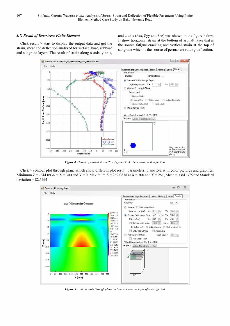
3.7. Result of Everstress Finite Element
Click result > start to display the output data and get the
strain, shear and deflection analyzed for surface, base, subbase
and subgrade layers. The result of strain along x-axis, y-axis,
and z-axis (Ɛxx, Ɛyy and Ɛzz) was shown in the figure below.
It show horizontal strain at the bottom of asphalt layer that is
the source fatigue cracking and vertical strain at the top of
subgrade which is the source of permanent rutting deflection.
Figure 4. Output of normal strain (Ɛxx, Ɛyy and Ɛzz), shear strain and deflection.
Click > contour plot through plane which show different plot result, parameters, plane xyz with color pictures and graphics.
Minimum Z = -244.0934 at X = 300 and Y = 0, Maximum Z = 269.0878 at X = 300 and Y = 251, Mean = 3.841375 and Standard
deviation = 82.3691.
Figure 5. contour plots through plane and show where the layer of road affected.

Journal of Civil, Construction and Environmental Engineering 2017; 2(4): 100-111 108
The following figure show the deflection of flexible pavement under the center of wheel load when the load applied on it.
Figure 6. The diagram show deflection of road at the center of wheel.
Figure 7. The graph shows the properties of strain on X-Z plane.

109 Shiferaw Garoma Wayessa et al.: Analysis of Stress- Strain and Deflection of Flexible Pavements Using Finite
Element Method Case Study on Bako-Nekemte Road
Contour plot through plane that show different plot results,
maximum, minimum, mean and their graphics are presented
as the following in different diagram, The analysis is being
carried out using the finite element computer package Visual
FEA. The results indicate that displacements under loading
are closest to mechanistic methods. This thesis study is being
under taken to incorporate the material properties of the
pavement layers and the moving traffic load, in the analysis of
the flexible pavement, using the finite element method. The
following table shows the road layers properties and the
general range of elastic modulus, poison’s ratio and their
typical values of different materials.
Comparison of laboratory test result and standard
specification of CBR procedure of elastic modulus, poison’s
ratio of different materials in case of Bako-Nekemte road, by
using EverstressFE to check stress, strain and deflection of
each layers parameters.
Table 9. Result of layered elastic analysis using EverstressFE.
CBR
procedure
Layer
No.
Depth: Z
Position
(mm)
Horizontal tensile strain at
the bottom of the asphalt
Layer(microstrain)
Vertical compressive
strain at the top of
subgrade(microstrain)
Shear stress of in the
flexible pavement
(microstrain)
Deflection in the
flexible pavement
(mm)
Ɛxx Ɛyy Ɛzz ɣxy ɣyz ɣzx ux uy uz
Standard
Specification
Result
1 0 -260.3 230.6 0.6 0.4 -42.8 0.4 -0.002 0 0.6
1 49 185.4 -348.6 49.8 0.02 4.2 -7.8 -0.004 0 0.6
2 51 118.4 -285.1 9.6 0.03 -0.7 -26.1 0.009 0 0.6
2 249 277.9 84.2 -385.1 0.06 -5.7 -114.4 0.02 0 0.6
3 251 276.2 83.5 -384.6 0.06 -5.6 -113.2 0.02 0 0.6
3 499 170.1 205.1 -330.2 0.07 -0.2 -109.5 0.04 0 0.5
4 501 169.3 209.2 -328.4 0.07 -0.2 109.1 0.04 0 0.5
Laboratory
Test Result
1 0 -217.3 185.2 1.3 -0.2 -0.2 0.4 -0.002 0 0.6
1 49 156.3 -311.1 48.5 -0.04 4.1 -8.1 -0.0001 0 0.6
2 51 -81.6 -84.7 -27.3 0.04 0.06 -51.5 -0.01 0 0.6
2 249 253.1 80.2 -311.3 0.04 -3.4 -72.7 0.02 0 0.5
3 251 244.2 80.4 -330.4 0.03 -2.9 -84.4 0.02 0 0.5
3 499 140.1 155.2 -323.1 0.02 -0.4 -118.2 0.03 0 0.4
4 501 140.0 155.8 -320.2 0.02 -0.4 -118.0 0.03 0 0.4
Comparison of general range of elastic modulus of different
materials in case of Bako-Nekemte road, which has been taken
from finite element software by using laboratory test result
and standard specification to check stress, strain and
deflection of each layers parameters. The following tables
shown the properties of strain in each layer of the road as well
as it shown where maximum strain and minimum strain were
presented. As the elastic modulus of asphalt concrete
increases horizontal strain and vertical strain distributes as
following table.
Table 10. The properties of horizontal and vertical strain when elastic modulus of asphalt concrete varies.
Elastic modulus in
asphalt concrete
Horizontal
strain in layer 1
Average vertical
strain in layer 1
Average vertical
strain in layer 2
Average vertical
strain in layer 3
Vertical strain at
depth 0mm in layer 4
Vertical strain at depth
150mm in layer 4
1500 1.6 55.9 -9.6 -229.9 -451.8 -382.5
2000 13.3 46.2 -12.8 -229.7 -447.3 -377.4
2500 22 39.4 -15.6 -230.1 -444.3 -373.7
3000 28.7 34.3 -18.3 -230.8 -442.1 -370.8
3500 33.8 30.3 -21 -231.7 -440.5 -368.4
The following table show the properties of horizontal strain and vertical strain in base course layer when the elastic modulus
increase.
Table 11. The vertical and horizontal strain in base layer as elastic modulus increases.
Elastic modulus in
base course
Horizontal
strain in layer 1
Average vertical
strain in layer 1
Average vertical
strain in layer 2
Average vertical
strain in layer 3
Vertical strain at
depth 0mm in layer 4
Vertical strain at depth
150mm in layer 4
200 97.6 28.3 -30.8 -237.3 -417.8 -405.2
300 53 32.1 -20.4 -232.6 -456.2 -384.8
400 29.1 34.2 -18.3 -230.8 -442.4 -371
500 14.1 35.6 -17.4 -229.9 -431.8 -330.3
600 3.8 36.4 -16.7 -229 -422.9 -351.3
700 0 36.9 -15.9 -228.1 -415.1 -343.3
800 0 37.3 -15.1 -226.9 -407.8 -336.1
1000 0 37.5 -13.5 -223.9 -494.6 -323.3
The following tables shown the distribution of horizontal strain and vertical strain in subbase course layer in case of elastic
modulus varies.

Journal of Civil, Construction and Environmental Engineering 2017; 2(4): 100-111 110
Table 12. The distribution of horizontal and vertical strain in subbase layer due to elastic modulus.
Elastic modulus in
subbase course
Horizontal
strain in layer 1
Average vertical
strain in layer 1
Average vertical
strain in layer 2
Average vertical
strain in layer 3
Vertical strain at
depth 0mm in layer 4
Vertical strain at depth
150mm in layer 4
100 31.6 37.4 -49.1 -428.1 -475.4 -394.6
150 30.1 35.1 -28.6 -284.6 -455.3 -380.3
200 28 34 -14.1 -211.8 -436.2 -366.6
250 26.1 33.2 -3.2 -168 -419.3 -354.5
The following table show the properties of horizontal strain and vertical strain in subgrade course layer when the elastic
modulus increase.
Table 13. The vertical and horizontal strain in subgrade layer as elastic modulus increases.
Elastic modulus in
subgrade course
Horizontal strain
in layer 1
Average vertical
strain in layer 1
Average vertical
strain in layer 2
Average vertical
strain in layer 3
Vertical strain at
depth 0mm in layer 4
Vertical strain at depth
150mm in layer 4
20 0 56.5 -6.1 -235.3 -871.3 -704.2
50 15 42.2 -13.3 -230.1 -590 -485.7
100 34.3 30.9 -20.7 -232.1 -382.8 -324.4
150 44.2 25 -25.3 -236.4 -282.2 -244.9
The maximum horizontal strain in layer 1 is 28.8 micro
strain and the average vertical strain in the layer 1 is 34.3
micro strain. The average vertical strain in the layer 2 is -18.3
microstrain while the average vertical strain in the layer 3 is
-230.8 microstrain. Vertical strain at depth 0mm in layer 4 is
-442.2 microstrain and at 150mm in layer 4 is -370.8
microstrain.
The maximum horizontal strain in layer 1 is 50.2 micro
strain and the average vertical strain in the layer 1 is 34.1
micro strain. The average vertical strain in the layer 2 is -22
microstrain while the average vertical strain in the layer 3 is
-245.3 microstrain. Vertical strain at depth 0mm in layer 4 is
-494.2 microstrain and at 150mm in layer 4 is -414.5
microstrain.
4. Conclusion
From this work, it can be concluded that to the cause of
stress, strain and deflection of flexible pavement was the load
came from vehicles, axle load, wheel pressures (load), and
elastic modulus of each road layers, road layers thickness and
poison ratio. The stress, strain and deflection of flexible
asphalt pavement can be reduced by using various design
parameters of each layers thickness: by increasing the hot mix
asphalt modulus and its layer thickness, increasing the base
course modulus and its layer thickness, increasing subbase
course modulus and its layer thickness and increasing
subgrade course modulus and its layer thickness. The value of
elastic modulus are various in each layers, E1 is varied from
1500 to 3500 MPa, E2 is varied from 200 to 1000MPa, E3 is
varied from 100 to 250 MPa and E4 is varied from 20MPa to
150MPa.
Therefore, at elastic modulus maximum in each layers, the
maximum horizontal strain in layer 1 is 0 microstrain and the
average vertical strain in the layer 1 is 24.6 micro strain. The
average vertical strain in the layer 2 is -11 microstrain while
the average vertical strain in the layer 3 is -171.8 microstrain.
Vertical strain at depth 0mm in layer 4 is -253.3 microstrains
and at 150mm in layer 4 is -214.7 microstrain.
The software can analysis of the stress, strain and deflection
of asphalt concrete, base and subbase courses, subgrade
course based on AASHTO guide 1993, laboratory test result,
existing laboratory result and Ethiopian Roads Authority
2001/2013 manual. EverstressFE can be used to predict the
performance of flexible pavement more easily and efficiently
since, it is more user-friendly. Subgrade modulus is the key
element that controls the excess vertical surface deflection in
flexible pavement. Hence, more efforts are required for
achieving high value of subgrade modulus as compared to
other top layers of pavement. Base course and surface layer
modulus have minor effects on the excess vertical surface
deflection in flexible pavement.
This study has been carried out in order to compare flexible
pavement performance using standard specification of
AASHTO, ERA and FEM computer programs, respectively.
Comparison of the output has been made to determine the
governing distress and deterioration models.
As observed above analysis from laboratory test result and
standard specification result, the vertical deflection reduces as
the modulus increases at all values of E. The maximum
horizontal strain in layer 1 is 28.8 micro strain and the average
vertical strain in the layer 1 is 34.3 micro strain. The average
vertical strain in the layer 2 is -18.3 microstrain while the
average vertical strain in the layer 3 is -230.8 microstrain.
Vertical strain at depth 0mm in layer 4 is -442.2 microstrain
and at 150mm in layer 4 is -370.8 microstrain.
The maximum horizontal strain in layer 1 is 50.2 micro
strain and the average vertical strain in the layer 1 is 34.1
micro strain. The average vertical strain in the layer 2 is -22
microstrain while the average vertical strain in the layer 3 is
-245.3 microstrain. Vertical strain at depth 0mm in layer 4 is
-494.2 microstrain and at 150mm in layer 4 is -414.5
microstrain.
Recommendation
This study was conducted in short time and limited budget,
human labor, thus, there are still several improvements that
can be made. In order to have complete software for flexible
pavement thickness design and elastic modulus, extensive

111 Shiferaw Garoma Wayessa et al.: Analysis of Stress- Strain and Deflection of Flexible Pavements Using Finite
Element Method Case Study on Bako-Nekemte Road
study and time frame is required.
Software is very important for design and analysis of new
highway and existing highway without create error (mistake).
So every institution in Ethiopia like Ethiopia Road Authority
and Regional State Road Authority have to use software rather
than hardcopy manual.
Therefore weather government or private design institution,
construction institution and consultant institution must use
software in future in case of road.
Rutting deflection and fatigue cracking are easily solved by
EverstressFE, to analysis and check stress, strain and
deflection of flexible pavement weather balance to each other.
Ethiopia road authorities have to consult all institution of
construction to develop software for road and to use software
for design and analysis of road.
The application of Everstress finite element can be used
only where computer is provided in contrast to manual design.
So the designer should equip himself with all the necessary
hard copy materials if the condition doesn't allow him to use
Everstress finite element.
EverstressFE executes AASHTO and ERA design manuals
only so it limits the range of comparison for better design or
research. Further study can be done to incorporate other
design methods.
References
[1] Burmister, D. (1945). The general theory of stresses and displacements in layered soil system. journal of applied physics,, vol. 16, pp. 84-94, 126-126-127, 296-302.
[2] De Beer M; Fisher C & Jooste F. (1997). Determination of Pneumatic Tire Pavement Interface Contact Stresses Under Moving Loads and Some Effects on Pavements with Thin Asphalt Surfacing Layers. Proceedings of 8th International Conference on Asphalt Pavements (Volume I), Seattle, Washington, pp. 179-227.
[3] Emmanuel O, E. a. (2009). Fatigue and rutting strain analysis of flexible pavements designed using CBR methods. African Journal of Environmental Science and Technology, Vol. 3 (1 2), pp. 41 2-421.
[4] Garba, R. (2002). A Thesis on Permanent Deformation properties of Asphalt Concrete mixtures. Department of Road and Railway Engineering, Norwegian University of Science and Technology.
[5] Gupta. (2014). COMPARATIVE STRUCTURAL ANALYSIS OF FLEXIBLE PAVEMENTS USING FINITE ELEMENT METHOD. The International Journal of Pavement Engineering and Asphalt Technology,, Volume: 15, pp.11-19.
[6] Huang Y. H. (1993). Pavement Analysis and Design. Englewood Cliffs, New Jersey, Prentice-Hall.
[7] Institute Asphalt. (1982). Research and Development of Asphalt Institute’s Thickness Design Manual. 9th Ed, Research Report 82-2.
[8] Lanham. (1996). National Asphalt Pavement Association Research and Education Foundation. Maryland.
[9] Machemehl R, Wang F & Prozzi J. (2005). Analytical study of effects of truck tire pressure on pavements with measured tire-pavement contact stress data. Transportation Research Record: J. Transp. Res. Board, 1919: 111-119.
[10] Markshek, K, Chen, H, & Hudso, R. C. (1986). Experimental Determination of Pressure Distribution of Truck Tire Pavement Contact, in Transportation Research Record 1070. pp.197-206.
[11] Ralph H.; Susan T.; Guy D.& David H. (2007). Mechanistic-Empirical pavement design. Evolution and future challenges. Canada.: Saskatoon.
[12] Shane Buchanan, (2007). Vulcan Materials Company, RESILIENT MODULUS: WHAT, WHY, AND HOW?Taneerananon, Somchainuek, Thongchim, & Yandell. (2014). ANALYSIS OF STRESS, STRAIN AND DEFLECTION OF PAVEMENTS USING FINITE ELEMENT. Journal of Society for Transportation and Traffic Studies, Vol. 1 No. 4.
[13] Yang, H. (1973). Asphalt Pavement Design – The Shell Method, Proceedings. 4th International Conference on Structural Design of Asphalt Pavements.
[14] Zaghloul S and White, T. (1993). Use of a ThreeDimensional, Dynamic Finite Element Program for Analysis of Flexible Pavement. In Transportation Research Record 1388, TRB, Washington D. C, pp. 6069.