Embed Size (px)
Citation preview
© 2008 Baylor University Slide 1
Analysis of Structures
© 2008 Baylor University Slide 2
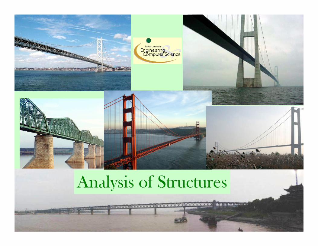
The truss is a simple skeletal structure. In design theory, the individual membersof a simple truss are only subject to tension (pulling) and compression (pushing)forces and not bending forces.
This is the Washington Ave. Bridge in Waco, Texas. It is the longest andoldest single span truss still in continuous use in Texas.
There are both simple and continuous trusses. The small size of individual partsof a truss make it the ideal bridge for places where large parts or sections cannotbe shipped. Because the truss is a hollow skeletal structure, the roadway maypass over or even through the structure allowing for clearance below the bridgeoften not possible with other bridge types.
Truss Bridges
© 2008 Baylor University Slide 3
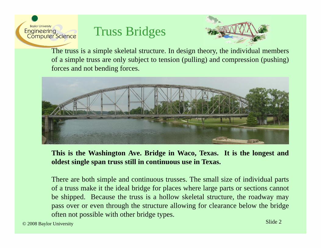
• Note that a suspension bridge like the Golden Gate also uses truss structures in the design.
• What are the Advantages in the suspension bridge design?• What are the Disadvantages in the suspension bridge design?
Suspension Bridges
© 2008 Baylor University Slide 4
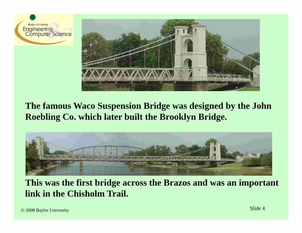
The famous Waco Suspension Bridge was designed by the John Roebling Co. which later built the Brooklyn Bridge.
This was the first bridge across the Brazos and was an important link in the Chisholm Trail.
© 2008 Baylor University Slide 5
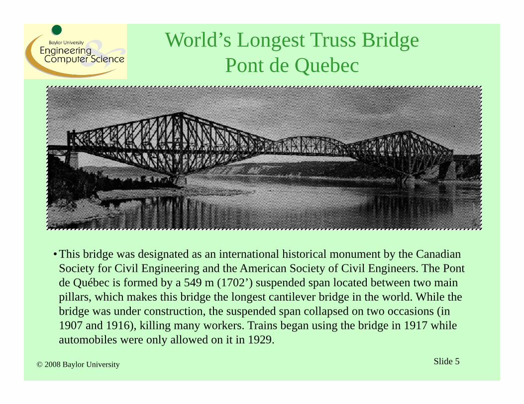
• This bridge was designated as an international historical monument by the Canadian Society for Civil Engineering and the American Society of Civil Engineers. The Pont de Québec is formed by a 549 m (1702’) suspended span located between two main pillars, which makes this bridge the longest cantilever bridge in the world. While the bridge was under construction, the suspended span collapsed on two occasions (in 1907 and 1916), killing many workers. Trains began using the bridge in 1917 while automobiles were only allowed on it in 1929.
World’s Longest Truss BridgePont de Quebec
© 2008 Baylor University Slide 6
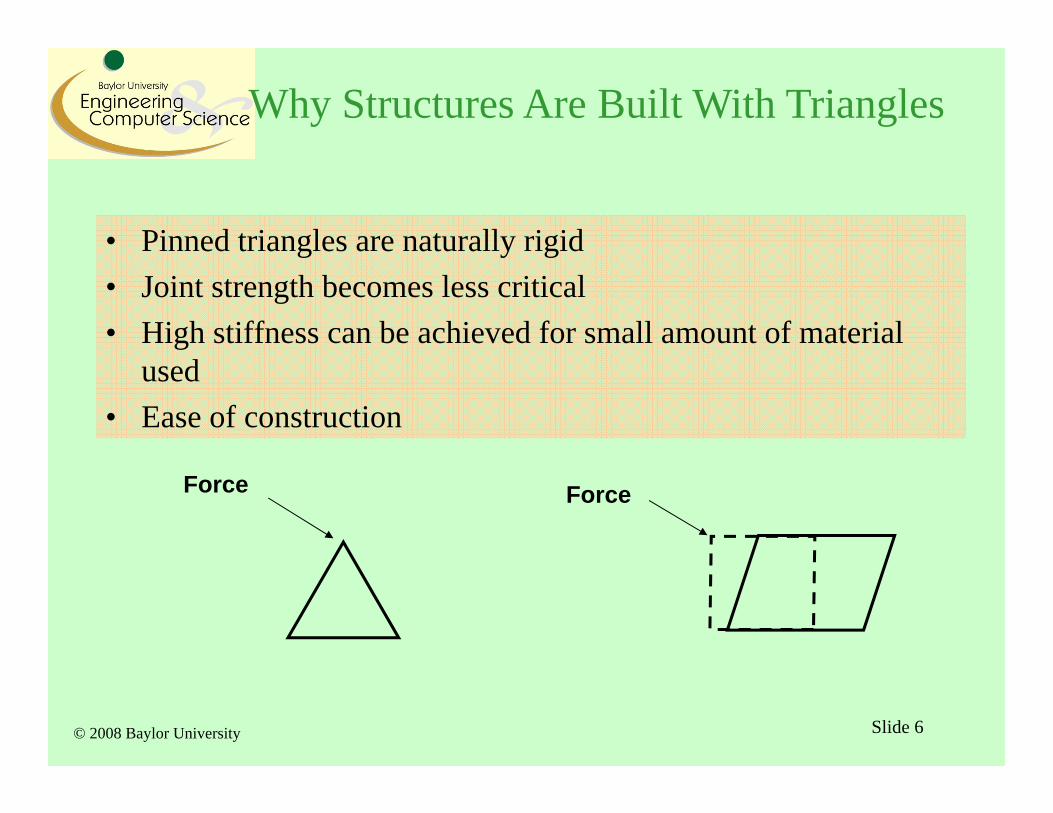
• Pinned triangles are naturally rigid• Joint strength becomes less critical• High stiffness can be achieved for small amount of material
used• Ease of construction
ForceForce
Why Structures Are Built With Triangles
© 2008 Baylor University Slide 7
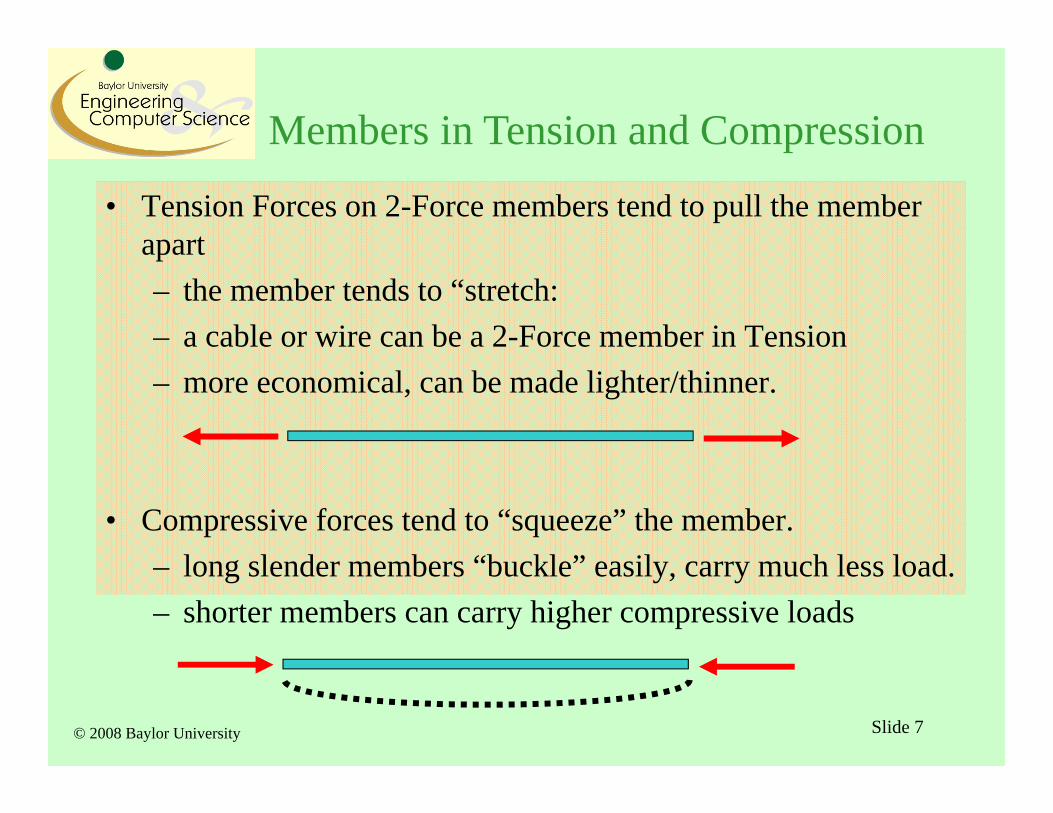
Members in Tension and Compression
• Tension Forces on 2-Force members tend to pull the member apart– the member tends to “stretch:– a cable or wire can be a 2-Force member in Tension– more economical, can be made lighter/thinner.
• Compressive forces tend to “squeeze” the member.– long slender members “buckle” easily, carry much less load.– shorter members can carry higher compressive loads
© 2008 Baylor University Slide 8
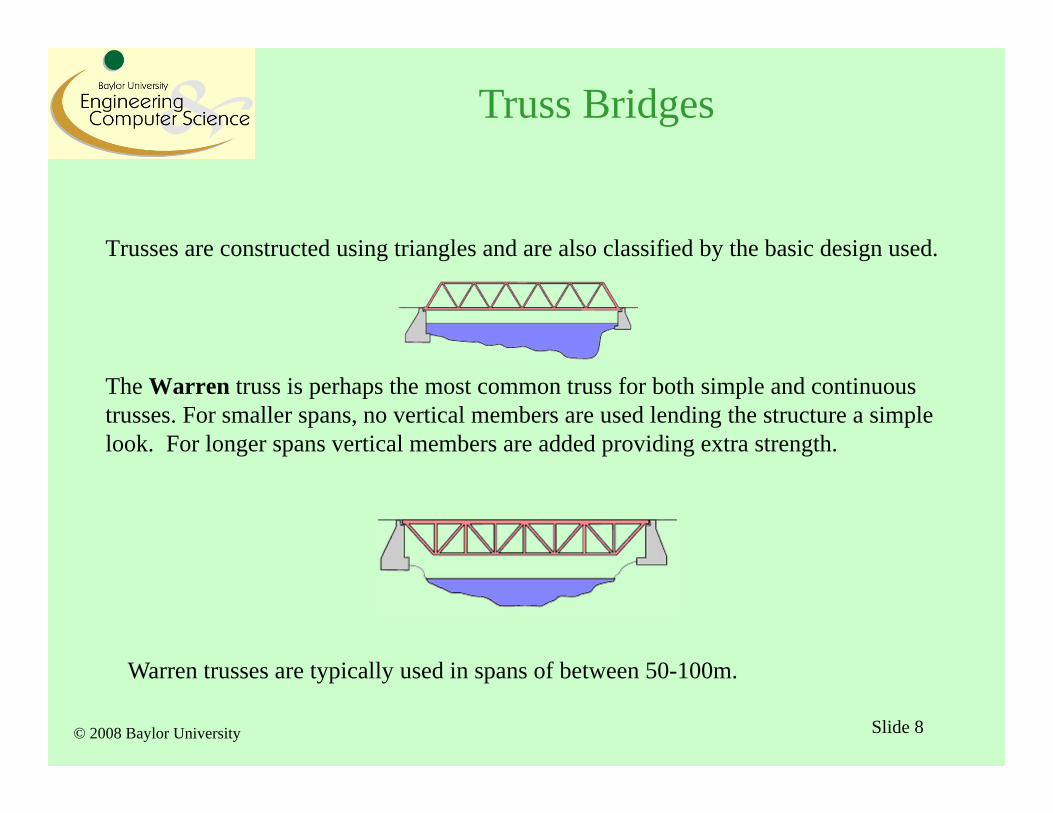
Trusses are constructed using triangles and are also classified by the basic design used.
The Warren truss is perhaps the most common truss for both simple and continuous trusses. For smaller spans, no vertical members are used lending the structure a simple look. For longer spans vertical members are added providing extra strength.
Warren trusses are typically used in spans of between 50-100m.
Truss Bridges
© 2008 Baylor University Slide 9
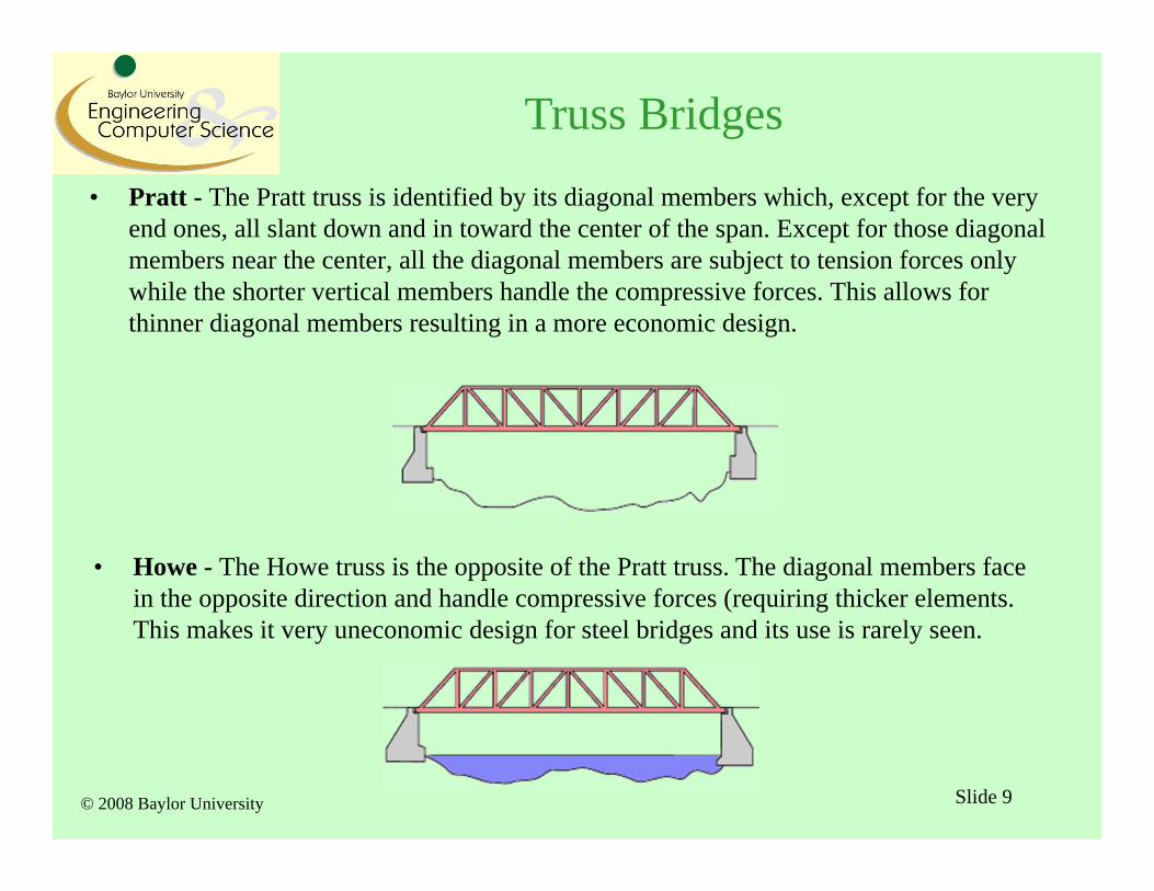
• Pratt - The Pratt truss is identified by its diagonal members which, except for the very end ones, all slant down and in toward the center of the span. Except for those diagonal members near the center, all the diagonal members are subject to tension forces only while the shorter vertical members handle the compressive forces. This allows for thinner diagonal members resulting in a more economic design.
• Howe - The Howe truss is the opposite of the Pratt truss. The diagonal members face in the opposite direction and handle compressive forces (requiring thicker elements. This makes it very uneconomic design for steel bridges and its use is rarely seen.
Truss Bridges
© 2008 Baylor University Slide 10
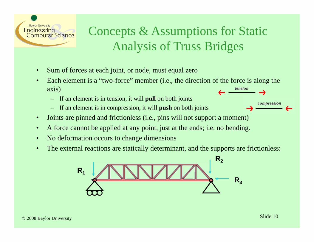
• Sum of forces at each joint, or node, must equal zero• Each element is a “two-force” member (i.e., the direction of the force is along the
axis)– If an element is in tension, it will pull on both joints– If an element is in compression, it will push on both joints
• Joints are pinned and frictionless (i.e., pins will not support a moment)• A force cannot be applied at any point, just at the ends; i.e. no bending.• No deformation occurs to change dimensions• The external reactions are statically determinant, and the supports are frictionless:
R1R3
R2
Concepts & Assumptions for Static Analysis of Truss Bridges
© 2008 Baylor University
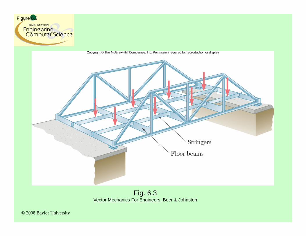
Figure 6.3
Fig. 6.3Vector Mechanics For Engineers, Beer & Johnston
© 2008 Baylor University Slide 12
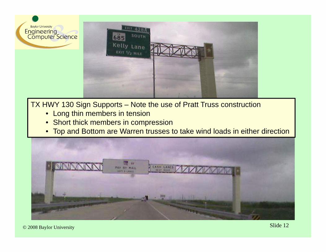
TX HWY 130 Sign Supports – Note the use of Pratt Truss construction• Long thin members in tension• Short thick members in compression• Top and Bottom are Warren trusses to take wind loads in either direction
© 2008 Baylor University Slide 13
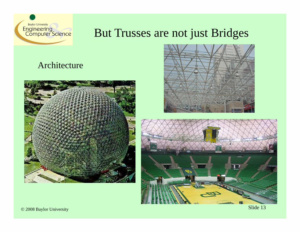
But Trusses are not just Bridges
Architecture
© 2008 Baylor University Slide 14
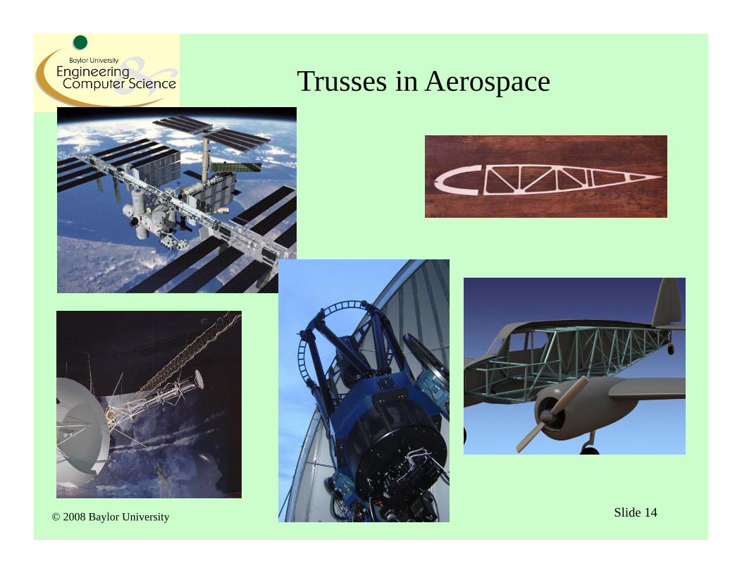
Trusses in Aerospace
© 2008 Baylor University
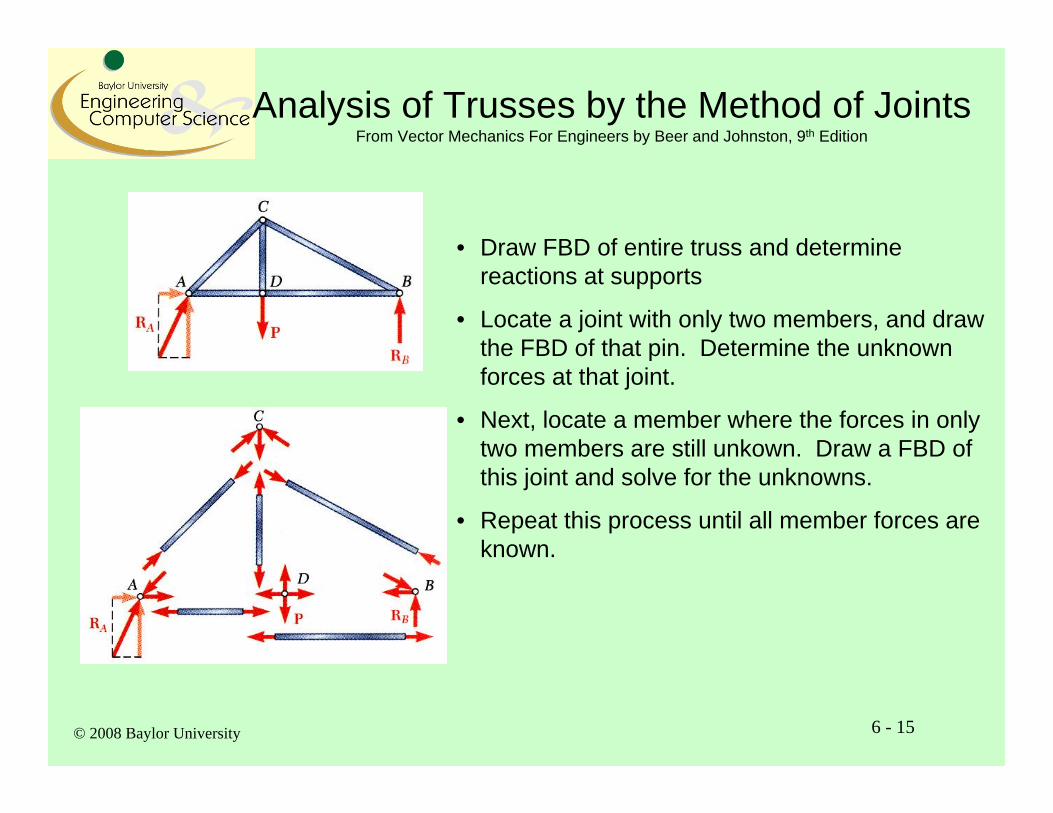
Analysis of Trusses by the Method of JointsFrom Vector Mechanics For Engineers by Beer and Johnston, 9th Edition
6 - 15
• Draw FBD of entire truss and determine reactions at supports
• Locate a joint with only two members, and draw the FBD of that pin. Determine the unknown forces at that joint.
• Next, locate a member where the forces in only two members are still unkown. Draw a FBD of this joint and solve for the unknowns.
• Repeat this process until all member forces are known.
© 2008 Baylor University
Joints Under Special Loading ConditionsFrom Vector Mechanics For Engineers by Beer and Johnston, 9th Edition
6 - 16
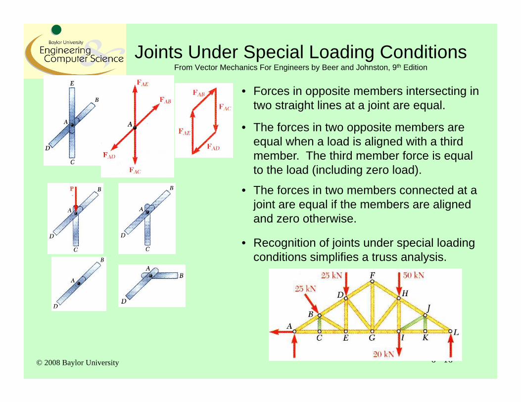
• Forces in opposite members intersecting in two straight lines at a joint are equal.
• The forces in two opposite members are equal when a load is aligned with a third member. The third member force is equal to the load (including zero load).
• The forces in two members connected at a joint are equal if the members are aligned and zero otherwise.
• Recognition of joints under special loading conditions simplifies a truss analysis.
© 2008 Baylor University
Sample Problem
6 - 17
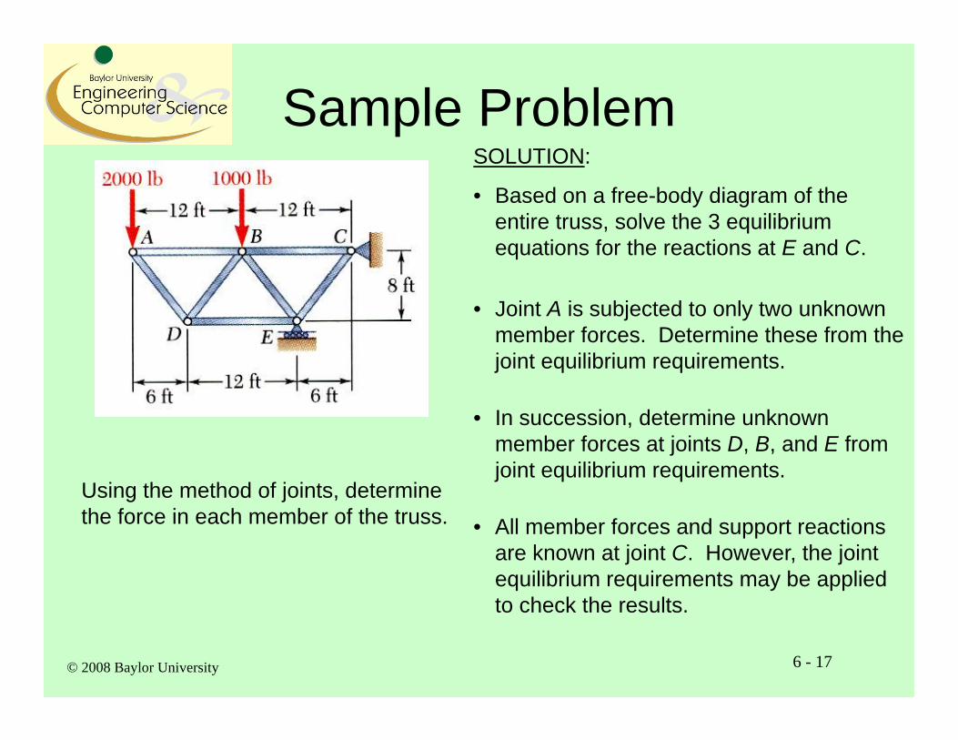
Using the method of joints, determine the force in each member of the truss.
SOLUTION:
• Based on a free-body diagram of the entire truss, solve the 3 equilibrium equations for the reactions at E and C.
• Joint A is subjected to only two unknown member forces. Determine these from the joint equilibrium requirements.
• In succession, determine unknown member forces at joints D, B, and E from joint equilibrium requirements.
• All member forces and support reactions are known at joint C. However, the joint equilibrium requirements may be applied to check the results.
© 2008 Baylor University
Sample Problem
6 - 18
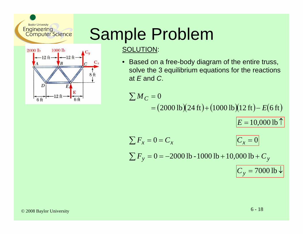
SOLUTION:
• Based on a free-body diagram of the entire truss, solve the 3 equilibrium equations for the reactions at E and C.
ft 6ft 12lb 1000ft 24lb 20000
EMC
lb 000,10E
xx CF 0 0xC
yy CF lb 10,000 lb 1000 - lb 20000
lb 7000yC
© 2008 Baylor University
Sample Problem
6 - 19
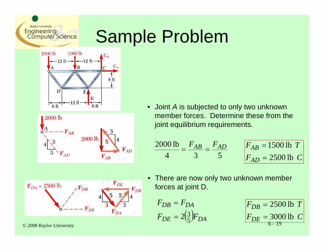
• Joint A is subjected to only two unknown member forces. Determine these from the joint equilibrium requirements.
534lb2000 ADAB FF
CFTF
AD
AB lb 2500 lb 1500
• There are now only two unknown member forces at joint D.
DADE
DADB
FF
FF
532
CFTF
DE
DB lb 3000 lb 2500
© 2008 Baylor University
Sample Problem
6 - 20
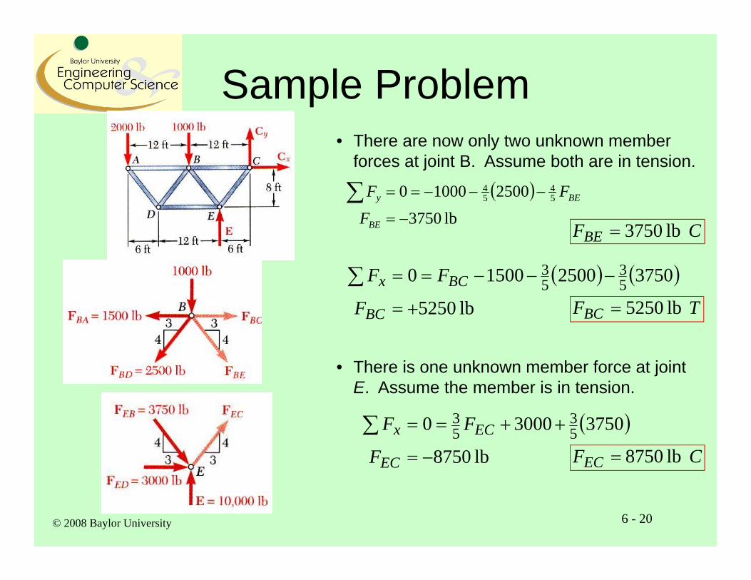
• There are now only two unknown member forces at joint B. Assume both are in tension.
lb 3750
250010000 54
54
BE
BEy
F
FF
CFBE lb 3750
lb 5250
3750250015000 53
53
BC
BCx
F
FF
TFBC lb 5250
• There is one unknown member force at joint E. Assume the member is in tension.
lb 8750
375030000 53
53
EC
ECx
F
FF
CFEC lb 8750
© 2008 Baylor University
Sample Problem
6 - 21
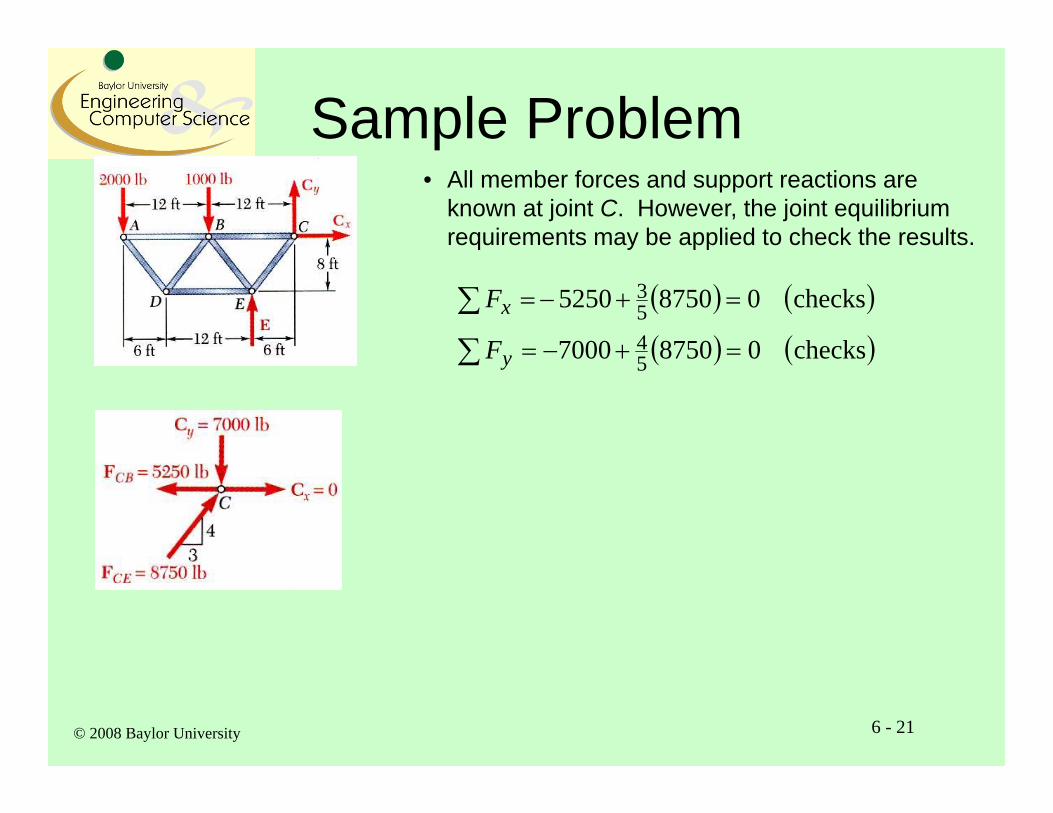
• All member forces and support reactions are known at joint C. However, the joint equilibrium requirements may be applied to check the results.
checks 087507000
checks 087505250
5453
y
x
F
F