Embed Size (px)
Citation preview
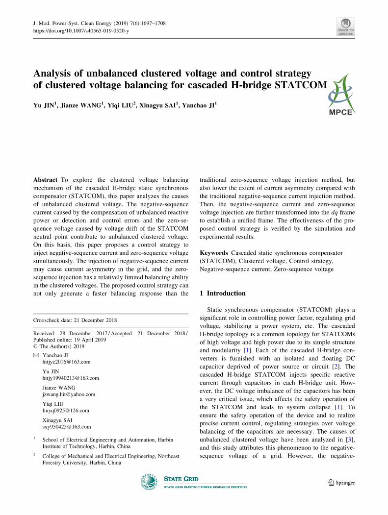
Analysis of unbalanced clustered voltage and control strategyof clustered voltage balancing for cascaded H-bridge STATCOM
Yu JIN1, Jianze WANG1, Yiqi LIU2, Xinagyu SAI1, Yanchao JI1
Abstract To explore the clustered voltage balancing
mechanism of the cascaded H-bridge static synchronous
compensator (STATCOM), this paper analyzes the causes
of unbalanced clustered voltage. The negative-sequence
current caused by the compensation of unbalanced reactive
power or detection and control errors and the zero-se-
quence voltage caused by voltage drift of the STATCOM
neutral point contribute to unbalanced clustered voltage.
On this basis, this paper proposes a control strategy to
inject negative-sequence current and zero-sequence voltage
simultaneously. The injection of negative-sequence current
may cause current asymmetry in the grid, and the zero-
sequence injection has a relatively limited balancing ability
in the clustered voltages. The proposed control strategy can
not only generate a faster balancing response than the
traditional zero-sequence voltage injection method, but
also lower the extent of current asymmetry compared with
the traditional negative-sequence current injection method.
Then, the negative-sequence current and zero-sequence
voltage injection are further transformed into the dq frame
to establish a unified frame. The effectiveness of the pro-
posed control strategy is verified by the simulation and
experimental results.
Keywords Cascaded static synchronous compensator
(STATCOM), Clustered voltage, Control strategy,
Negative-sequence current, Zero-sequence voltage
1 Introduction
Static synchronous compensator (STATCOM) plays a
significant role in controlling power factor, regulating grid
voltage, stabilizing a power system, etc. The cascaded
H-bridge topology is a common topology for STATCOMs
of high voltage and high power due to its simple structure
and modularity [1]. Each of the cascaded H-bridge con-
verters is furnished with an isolated and floating DC
capacitor deprived of power source or circuit [2]. The
cascaded H-bridge STATCOM injects specific reactive
current through capacitors in each H-bridge unit. How-
ever, the DC voltage imbalance of the capacitors has been
a very critical issue, which affects the safety operation of
the STATCOM and leads to system collapse [1]. To
ensure the safety operation of the device and to realize
precise current control, regulating strategies over voltage
balancing of the capacitors are necessary. The causes of
unbalanced clustered voltage have been analyzed in [3],
and this study attributes this phenomenon to the negative-
sequence voltage of a grid. However, the negative-
Crooscheck date: 21 December 2018
Received: 28 December 2017 / Accepted: 21 December 2018 /
Published online: 19 April 2019
� The Author(s) 2019
& Yanchao JI
Yu JIN
Jianze WANG
Yiqi LIU
Xinagyu SAI
1 School of Electrical Engineering and Automation, Harbin
Institute of Technology, Harbin, China
2 College of Mechanical and Electrical Engineering, Northeast
Forestry University, Harbin, China
123
J. Mod. Power Syst. Clean Energy (2019) 7(6):1697–1708
https://doi.org/10.1007/s40565-019-0520-y

sequence voltage only accounts for a small portion of the
grid voltage; therefore, there should also be other causes
for this phenomenon.
To solve the problem of unbalanced DC voltage across
each floating capacitor, various research works have been
carried out and the resultant papers have been published in
[1–23]. The hierarchical voltage balancing structure is first
proposed to solve the imbalance problem in [4]. The
voltage balancing can be divided into three layers,
including overall voltage control, clustered voltage bal-
ancing control, and individual voltage balancing control.
This paper mainly focuses on the second layer, clustered
voltage balancing control. For overall voltage control, a
proportional-integral (PI) controller in the dq frame is
usually adopted to regulate the sum of voltages of all the
capacitors in three phases [4, 17, 22]. For individual volt-
age balancing control, multiple research studies have been
conducted in [5–12]. The individual phase instantaneous
current tracking method is employed in [5] to control the
voltage of each DC capacitor. Reference [6] adopts a novel
balance control method for individual DC voltage balanc-
ing based on the popular carrier phase-shifted sinusoidal
pulse-width modulation (PWM) strategy, and this method
makes the control strategy simpler and more flexible.
References [13–15] have further proposed the individual
voltage balancing strategy based on space vector modula-
tion and another method of current injection, the root-
mean-square (RMS) of which is zero, as presented in
[16].
For a clustered voltage balancing control, the PI con-
troller is first adopted to regulate the DC clustered voltages
of the capacitors in [4]. On this basis, the clustered voltage
balancing strategy based on the loop-gain shaping con-
troller in the dq frame is described in [22]. However, the
injection components of these clustered voltage balancing
strategies are not analyzed and the injection components
may include positive-sequence and other components that
may not be necessary for the clustered voltage balancing.
This may lower the efficiency and affect the balancing
strategy. Therefore, the voltage balancing technique based
on negative-sequence current injection [17] and zero-se-
quence voltage injection [18] is proposed to eliminate the
imbalance of the voltage between the clusters. Based on
[17], a new clustered voltage balancing control is realized
by regulating the negative-sequence modulation reference
voltage in the dq frame [1]. Considering the merits and
demerits of zero-sequence voltage and negative-sequence
current injection, one of the two kinds of injection is
applied according to the load currents of the grid in
[19, 23]. The zero-sequence voltage injection may lower
the DC voltage utilization and have a relatively limited
ability in the clustered voltage balancing, while the nega-
tive-sequence current injection results in significant peak
current and even triggers the current asymmetry of the
power grid. Thus, voltage balancing strategies to improve
the DC voltage utilization by regulating the effectiveness
between the zero-sequence voltage and negative-sequence
current injection are proposed [20]. On the basis of these
studies, reference [21] provided the voltage balancing
strategy to manage the peak current and the modulation
index simultaneously. However, it should be noted that the
possible demerits, current asymmetry of the grid caused by
the negative-sequence injection and the limited ability in
the clustered voltage balancing of the zero-sequence
injection, remain to be solved.
This paper first analyzes the causes of the unbalanced
clustered voltage. The negative-sequence current caused by
the unbalanced loads and the zero-sequence voltage caused
by the voltage drift of the STATCOM neutral point con-
tribute to this unbalanced clustered voltage. On this basis, a
novel control strategy to inject the negative-sequence
current and zero-sequence voltage simultaneously is pro-
posed. The proposed control strategy can generate a faster
balancing response. It also lowers the extent of current
asymmetry by reducing the negative-sequence current
injection. To establish a unified frame, the negative-
sequence and zero-sequence injections are further trans-
formed into the dq frame. The effectiveness of the pro-
posed control strategy is verified by simulation and
experimental results.
Load
A-phasecluster
N
O
Udc,1
Udc,2
Udc,N
C
C
C
C
C
C C
C
C
L L LuaN ubN ucN
uscN iLc
usbN iLb
usc
usb
usaN iLausa
+
+
+−
−
−ia ib ic
Fig. 1 Circuit configuration of cascaded STATCOM
1698 Yu JIN et al.
123

2 System configuration
The circuit configuration of the cascaded STATCOM is
shown in Fig. 1. The cascaded STATCOM is composed of
three identical clusters with a star connection. Each cluster
consists of N series of H-bridge units and is connected to
the grid through an inductance L. usa, usb, and usc are the
three-phase grid voltages; uaN, ubN, and ucN are the three-
phase output voltages of the STATCOM; iLa, iLb, and iLcare the three-phase currents of the grid loads; ia, ib, and icare the three-phase output currents of the STATCOM;
Udc,1, Udc,2, and Udc,N represent the voltages across each
capacitor.
3 Analysis of unbalanced clustered voltage
In practical engineering projects, the phenomenon of
unbalanced clustered voltages is quite common. Most lit-
eratures attribute this phenomenon to the difference of the
electronic devices and the unbalanced grid voltage. How-
ever, there are other important factors that trigger this
problem and few literature studies have been conducted to
explore the causes behind this.
Most literatures have not provided any specific instruc-
tion on how to measure the output voltage of the cascaded
STATCOM and decompose it into only the positive-se-
quence component [1, 7, 8] and some with minor portions
of the negative-sequence component [19–21]. The com-
ponent of the output voltage is the same as the grid voltage
in these circumstances. However, they have not considered
the zero-sequence voltage [17, 18]. The voltage of each
cluster is a reflection of the active power flow of the
STATCOM, and the active power flow of each cluster
should be calculated with the output voltage and current of
the cascaded STATCOM, i.e., uaN, ubN, ucN, ia, ib, and ic.
The active power flow of the converters are replaced with
the active power flow of converter together with the
inductor in this study because the inductor will absorb no
active power from either the grid or the converter. There-
fore, the cluster voltages used to calculate the active power
flow, uaN, ubN, and ucN, can be replaced by usaN, usbN, and
uscN, as shown in Fig. 1.
The following equations (1)–(3) are derived based on
the following assumptions:
1) The grid voltages are balanced and only the positive-
sequence voltage exists.
2) The STATCOM generates only the reactive power to
correct the power factor, and no additional injection is
included to balance the voltage of each capacitor.
Then, the output voltage of each cluster and the current
of the cascaded STATCOM can thus be expressed as (1)
and (2), respectively.
usaN
usbN
uscN
2664
3775 ¼
usa
usb
usc
2664
3775þ
uON
uON
uON
2664
3775
¼ Up
cosxt
cos xt � 2
3p
� �
cos xt þ 2
3p
� �
26666664
37777775þ U0
cosðxt þ /0Þ
cosðxt þ /0Þ
cosðxt þ /0Þ
2664
3775
ð1Þ
where Up is the amplitude of the positive-sequence voltage
of the grid; x is the grid frequency; U0 and /0 are the
amplitude and the phase angle of the zero-sequence
voltage, uON, caused by the voltage drift of the neutral
point, respectively.
iaibic
24
35 ¼ Ip
cosðxt þ upÞ
cos xt þ up �2
3p
� �
cos xt þ up þ2
3p
� �
266664
377775
þ In
cosðxt þ unÞcos xt þ un þ
2
3p
� �
cos xt þ un �2
3p
� �
266664
377775
ð2Þ
where Ip and up are the amplitude and the phase angle of
the positive-sequence output current, respectively; In and
un are the amplitude and the phase angle of the negative-
sequence output current caused by the compensation of
unbalanced loads or detection and control errors,
respectively.
The active power flow of each cluster can thus be
expressed as:
Pa
Pb
Pc
2664
3775 ¼ 1
T
Z T
0
usaNia
usbNib
uscNic
2664
3775dt
¼cosup cosun cosð/0 � upÞ cosð/0 � unÞcosup cosðun � 2p=3Þ cosð/0 � up þ 2p=3Þ cosð/0 � un � 2p=3Þcosup cosðun þ 2p=3Þ cosð/0 � up � 2p=3Þ cosð/0 � un þ 2p=3Þ
264
375
UpIp
UpIn
U0Ip
U0In
26664
37775
ð3Þ
where T is the time of each period. It can be seen from (3)
that UpIpcosup is the same component of Pa, Pb, and Pc that
will contribute no imbalance to the three phases. The
negative-sequence current caused by the compensation of
the unbalanced loads or detection and control errors, and
Analysis of unbalanced clustered voltage and control strategy of clustered voltage balancing… 1699
123

the zero-sequence voltage caused by the voltage drift of the
STATCOM neutral point contribute to the unbalanced
voltage of each cluster. This phenomenon is thus
inevitable.
4 Control strategy of cascaded STATCOM
Figure 2 illustrates the overall control block diagram of
the cascaded STATCOM. The control diagram can be
divided into three layers. The first layer, active/reactive
power control, is designed to control the overall DC volt-
age Udc,sum and correct the grid power factor by generating
a reactive power. The second layer, clustered voltage bal-
ancing control, aims to balance the three clustered voltages
Udca, Udcb, and Udcc. The third layer, an individual voltage
balancing control, is to regulate the voltage of each
capacitor (Udckj, k = a, b, c, j = 1, 2, …, N). This paper
mainly focuses on the control strategy of the second layer.
4.1 Transformation between different frames
The overall DC voltage control and reactive power
control is conducted under the dq frame. However, the
traditional clustered voltage balancing control has been
calculated in the form of symmetrical components (posi-
tive-sequence, negative-sequence, and zero-sequence). In
order to keep pace with the dq rotating frame, this paper
puts forward a clustered voltage balancing control strategy
conducted in the dq frame.
Tdq0pn0 ¼ Tdq0
ab0Tab0abcT
abcpn0 ð4Þ
Tpn0dq0 ¼ ðTdq0
pn0Þ�1 ¼ ðTabc
pn0Þ�1ðTab0
abc Þ�1ðTdq0
ab0Þ�1 ð5Þ
Tdq0ab0 ¼
sinxt � cosxt 0
� cosxt � sinxt 0
0 0 1
24
35 ð6Þ
Tab0abc ¼ 2
3
1 � 1
2� 1
2
0
ffiffiffi3
p
2�
ffiffiffi3
p
21
2
1
2
1
2
2666664
3777775
ð7Þ
Tabcpn0 ¼
1 1 1
a2 a 1
a a2 1
24
35 ð8Þ
where Tdq0pn0 is the transformation matrix from sequence
frame (positive negative and zero sequence) to dq frame;
Tpn0dq0 is the opposite transformation matrix from dq frame to
sequence frame; Tabcpn0 is the transformation matrix from
sequence frame to abc frame; Tab0abc is the transformation
matrix from abc frame to ab frame; Tdq0ab0 is the transfor-
mation matrix from ab frame to dq frame; a ¼ ej120�.
Equations (4)–(8) are the transformation matrices in this
study, (9) and (10) exhibit the transformation between the
symmetrical components and the dq frame.
udq0 ¼ Tdq0pn0upn0
idq0 ¼ Tdq0pn0ipn0
(ð9Þ
upn0 ¼ Tpn0dq0udq0
ipn0 ¼ Tpn0dq0idq0
(ð10Þ
4.2 Overall DC voltage control and reactive power
control
In this study, the d-axis current and q-axis current were
injected individually to control the overall DC voltage and
reactive power. Figure 3 shows the block diagram of the
overall DC voltage control and reactive power control.
∑∑∑
PWM12N
∑
−
+−
+−
dq
abctodq
PI
PIPI
Clustered voltagebalancing control
dq0to
abc
Active/reactive power control
MC
NNN
uaref
ubref
ucref
Individual voltagebalancing control
++
N
+
N
+
+
N
NNN
Udcaj
Udcbj
Udccj
Udca
Udcb
Udcc
Udc,sum
+
Uabc
iLabc
iabcidiq
++
+
+
Modulation wavecalculation
++
+
*δu0*δ id *δ iq
Udc,sum*
*iq
*id
++ +
+
Fig. 2 Overall control block diagram of the cascaded STATCOM
Fig. 3 Block diagram of the overall DC voltage control and reactive
power control
1700 Yu JIN et al.
123

Equations (11) and (12) reveal that if the d-axis and q-axis
component injections are constant, then they can be
transformed into the positive-sequence component exclu-
sively, which will not affect the balance of the clustered
voltage. The d-axis current injection is calculated as (13)
and the q-axis current injection is calculated as (14).
ia
ib
ic
264
375 ¼ Tabc
dq0
id
iq
i0
264
375 ¼ ðTab0
abc Þ�1ðTdq0
ab0Þ�1
id
iq
i0
264
375 ð11Þ
Tabcdq0 ¼
sinxt � cosxt 1
� 1
2sinxt�
ffiffiffi3
p
2cosxt
1
2cosxt�
ffiffiffi3
p
2sinxt 1
� 1
2sinxtþ
ffiffiffi3
p
2cosxt
1
2cosxtþ
ffiffiffi3
p
2sinxt 1
26664
37775
ð12Þ
i�d ¼ KPov þKIov
S
� �U�
dc;sum � Udc;sum
� �ð13Þ
i�q ¼ �Qload=Ud ð14Þ
where Tabcdq0 is the transformation matrix from dq frame to
abc frame; KPov and KIov are the proportional and integral
gains in the PI control loop of the overall DC voltage; Qload
is the reactive power generated by the grid loads; Ud is the
d-axis component of the output voltages; U�dc;sum is the
reference of overall DC voltage Udc;sum.
4.3 Clustered voltage balancing control
Clustered voltage balancing control focuses on regulat-
ing the sum voltage of capacitors in each phase cluster and
the control target is to keep Udca, Udcb and Udcc equal to the
average value.
According to (1) to (3), extra negative-sequence current
and zero-sequence voltage injection is necessary since the
phenomenon of unbalanced cluster voltage is inevitable.
Extra negative-sequence current injection will cause cur-
rent asymmetry of power grid but has a high efficiency in
clustered voltage balancing while extra zero-sequence
voltage injection generates no additional influence on
current asymmetry but has a relatively low efficiency in
clustered voltage balancing. This paper proposes a novel
control strategy which injects the negative-sequence cur-
rent and zero-sequence voltage at the same time. The
proposed control strategy can not only generate a stronger
balancing ability and a faster balancing response than tra-
ditional zero-sequence voltage injection methods, but also
lower the extent of current asymmetry compared with
traditional negative-sequence current injection methods.
The block diagram of the proposed clustered voltage bal-
ancing control is shown in Fig. 4. In Fig. 4, du0 and din are
the zero-sequence voltage and negative-sequence current
injected to balance the clustered voltages and they are
further transformed into du0*, did
*, and diq*.
1) Overall control strategy: The output voltage, current
and active power flow of cascaded STATCOM including
no extra injection to balance the voltage of each capacitor
are depicted in (1) to (3), and the corresponding voltage,
current and additional active power flow of cascaded
STATCOM with extra negative-sequence current and zero-
sequence voltage injection are illustrated in (15) to (17).
u0saNu0sbNu0scN
24
35 ¼ Up
cosxt
cos xt � 2
3p
� �
cos xt þ 2
3p
� �
26664
37775þ U0
cosðxt þ /0Þcosðxt þ /0Þcosðxt þ /0Þ
24
35
þ dU0
cos xt þ /00
� �cos xt þ /0
0
� �cos xt þ /0
0
� �
24
35
ð15Þ
i0ai0bi0c
24
35 ¼ Ip
cosðxt þ upÞ
cos xt þ up �2
3p
� �
cos xt þ up þ2
3p
� �
266664
377775
þ In
cosðxt þ unÞcos xt þ un þ
2
3p
� �
cos xt þ un �2
3p
� �
266664
377775
þ dIn
cos xt þ u0n
� �
cos xt þ u0n þ
2
3p
� �
cos xt þ u0n �
2
3p
� �
266664
377775
ð16Þ
Fig. 4 Block diagram of the proposed clustered voltage balancing
control
Analysis of unbalanced clustered voltage and control strategy of clustered voltage balancing… 1701
123

where dU0 and /00 are the amplitude and phase angle of
du0; dIn and u0n are the amplitude and phase angle of din.
The higher order minima of power flow, du0din, is omitted
in (17). However, there are four variables (dU0, dIn, /00 and
u0n) in two linear independent equations according to the
referential power flow of each phase cluster, as dPa-
? dPb ? dPc = 0. So, this paper will add additional
restrictive conditions to make the maximum utilization of
the two kinds of injection. These restrictive conditions will
help to calculate two of the variables, /00 and u0
n, respec-
tively. Then, the four variables will be calculated according
to the two-linear independent equation in (17), thus
deriving the negative-sequence current and zero-sequence
voltage injection components.
2) Calculation of phase angle: The phase angles of zero-
sequence voltage injection and negative-sequence current
injectionare calculatedaccording to the followingprinciples.
The selection principles of phase angle for injection of
zero-sequence voltage are discussed first. In order to make
maximum utilization of the zero-sequence voltage injection,
the phase angle /00 can be calculated using two alternative
principles. The first principle is to provide the maximum
active power flow with the same amplitude of dU0, and the
phase angle /00 is calculated using (18)–(20).
If max jdP�a j; jdP�
bj; jdP�c j
¼ jdP�
a j, then
/00 ¼
up dP�a � 0
up þ p dP�a\0
�ð18Þ
If max jdP�a j; jdP�
bj; jdP�c j
¼ jdP�
bj, then
/00 ¼
up � 2p/3 dP�b � 0
up þ p=3 dP�b\0
�ð19Þ
If max jdP�a j; jdP�
bj; jdP�c j
¼ jdP�
c j, then
/00 ¼
upþ2p=3d P�c � 0
up � p=3 dP�c\0
(ð20Þ
The second principle is to alter the least amplitude of
overall voltage in each phase cluster with the same
amplitude of dU0, and the phase angle /00 is calculated
using (21)–(23).
Both the principles are effective. However, the first
principle can generate more significant effect on the active
power flow. This paper adopts the first principle to calcu-
late the phase angle of zero-sequence voltage injection.
If max jdP�a j; jdP�
bj; jdP�c j
¼ jdP�
a j, then
/00 ¼
0 dP�a � 0
p dP�a\0
�ð21Þ
If max jdP�a j; jdP�
bj; jdP�c j
¼ jdP�
bj, then
/00 ¼
�2p/3 dP�b � 0
p=3 dP�b\0
�ð22Þ
If max jdP�a j; jdP�
bj; jdP�c j
¼ jdP�
c j, then
/00 ¼
2p/3 dP�c � 0
�p=3 dP�c\0
�ð23Þ
The selection principles of the phase angle for injection
of zero-sequence voltage are then discussed.
In order to make the maximum utilization of negative-
sequence current injection, the phase angle u0n is calculated
using (24)–(26) to achieve the maximum active power flow
with the same amplitude of dIn.
3) Calculation of amplitudes: With the phase angle /00 and
u0n calculated earlier, the amplitude of zero-sequence voltage
and negative-sequence current, dU0 and dIn, can be expressedas (27) by substituting (18)–(20) and (24)–(26) into (17).
If max jdP�a j; jdP�
bj; jdP�c j
¼ jdP�
a j, then
u0n ¼
0 dP�a � 0
p dP�a\0
�ð24Þ
If max jdP�a j; jdP�
bj; jdP�c j
¼ jdP�
bj, then
u0n ¼
2p=3 dP�b � 0
�p=3 dP�b\0
�ð25Þ
If max jdP�a j; jdP�
bj; jdP�c j
¼ jdP�
c j, then
u0n ¼
�2p=3 dP�c � 0
p=3 dP�c\0
�ð26Þ
dU0 ¼H1dP�
b � H2dP�a
H1H3 � H2H4
dIn ¼H4dP�
b � H3dP�a
H2H4 � H1H3
8>><>>:
ð27Þ
where dP�a and dP�
b are active power instructions of phase
A and phase B. H1, H2, H3 and H4 are shown in (28).
dPa
dPb
dPc
2664
3775 ¼
cosu0n cosð/0 � u0
nÞ cos /00 � up
� �cos /0
0 � un
� �
cos u0n � 2p=3
� �cos /0 � u0
n � 2p=3� �
cos /00 � up þ 2p=3
� �cos /0
0 � un � 2p=3� �
cos u0n þ 2p=3
� �cos /0 � u0
n þ 2p=3� �
cos /00 � up � 2p=3
� �cos /0
0 � un þ 2p=3� �
264
375
UpdInU0dIndU0Ip
dU0In
26664
37775 ð17Þ
1702 Yu JIN et al.
123
H1 ¼ Up cosu0n þ U0 cos /0 � u0
n
� �
H2 ¼ Up cos u0n � 2p=3
� �þ U0 cos /0 � u0
n � 2p=3� �
H3 ¼ Ip cos /00 � up þ 2p=3
� �þ I0 cos /0
0 � un � 2p=3� �
H4 ¼ Ip cos /00 � up
� �þ I0 cos /0
0 � un
� �
8>>>><>>>>:
ð28Þ
4) Transformation into dq frame: With the calculated
phase angle and amplitude of extra zero-sequence voltage
and negative-sequence current, the injection components
are expressed in (29). In order to establish a unified frame,
the extra zero-sequence voltage and negative-sequence
current injection are then transformed into dq frame as (30)
by substituting (18)–(29) into (9).
du0 ¼ dU0 cosðxt þ /00Þ
din ¼ dIn cosðxt þ u0nÞ
(ð29Þ
du0 ¼ dU0 cosðxt þ /00Þ
did ¼ dInðcosðxt þ u0nÞ sinxt þ sinðxt þ u0
nÞ cosxtÞdiq ¼ dInðsinðxt þ u0
nÞ sinxt � cosðxt þ u0nÞ cosxtÞ
8><>:
ð30Þ
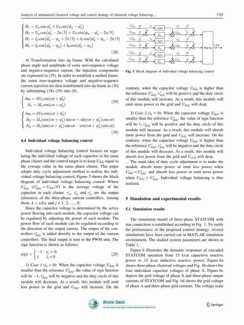
4.4 Individual voltage balancing control
Individual voltage balancing control focuses on regu-
lating the individual voltage of each capacitor in the same
phase cluster and the control target is to keep Udckj equal to
the average value in the same phase cluster. This paper
adopts duty cycle adjustment method to realize the indi-
vidual voltage balancing control. Figure 5 shows the block
diagram of individual voltage balancing control. Where
U�dckj (U�
dckj ¼ Udck=N) is the average voltage of the
capacitor in each cluster. v�ia, v�ib and v�ic are the output
references of the three-phase current controllers. Among
them, k ¼ a,b,c and j = 1, 2, …, N.
Since the capacitor voltage is determined by the active
power flowing into each module, the capacitor voltage can
be regulated by adjusting the power of each module. The
power flow of each module can be regulated according to
the direction of the output current. The output of the con-
trollers v�dckj is added directly to the output of the current
controllers. The final output is sent to the PWM unit. The
sign function is shown as follows:
sign ¼ �1 ik [ 0
1 ik\0
�ð25Þ
1) Case 1 (ik[ 0): When the capacitor voltage Udckj is
smaller than the reference U�dckj, the value of sign function
will be -1, v�dckj will be negative and the duty circle of this
module will decrease. As a result, this module will emit
less power to the grid and Udckj will increase. On the
contrary, when the capacitor voltage Udckj is higher than
the reference U�dckj, v
�dckj will be positive and the duty circle
of this module will increase. As a result, this module will
emit more power to the grid and Udckj will drop.
2) Case 2 (ik\ 0): When the capacitor voltage Udckj is
smaller than the reference U�dckj, the value of sign function
will be 1, v�dckj will be positive and the duty circle of this
module will increase. As a result, this module will absorb
more power from the grid and Udckj will increase. On the
contrary, when the capacitor voltage Udckj is higher than
the reference U�dckj, v
�dckj will be negative and the duty circle
of this module will decrease. As a result, this module will
absorb less power from the grid and Udckj will drop.
The main idea of duty cycle adjustment is to make the
module absorb more power or emit less power when
Udckj\U�dckj, and absorb less power or emit more power
when Udckj [U�dckj. Individual voltage balancing is thus
realized.
5 Simulation and experimental results
5.1 Simulation results
The simulation model of three-phase STATCOM with
star connection is established according to Fig. 1. To verify
the performance of the proposed control strategy, several
simulations have been carried out in MATLAB simulation
environment. The studied system parameters are shown in
Table 1.
Figure 6 illustrates the dynamic responses of cascaded
STATCOM operation from 15 kvar capacitive reactive
power to 15 kvar inductive reactive power. Figure 6a
shows three-phase clustered voltages and Fig. 6b shows the
four individual capacitor voltages of phase A. Figure 6c
depicts the grid voltage of phase A and three-phase output
currents of STATCOM and Fig. 6d shows the grid voltage
of phase A and three-phase grid currents. The voltage scale
Kiv
Kiv
Kiv
+
−
+
−
+
−
+
+
+
PWM
*Udcaj
Udcaj
*Udcbj
Udcbj
*Udccj
Udccj
N
N
N
N
N
N
*vdcaj
+
+
+
*vdcbj
*vdccj
12N
signia
signib
signic
N
N
N
N
N
N
*via
*vib
*vic
+
+
++
+
+
Fig. 5 Block diagram of individual voltage balancing control
Analysis of unbalanced clustered voltage and control strategy of clustered voltage balancing… 1703
123
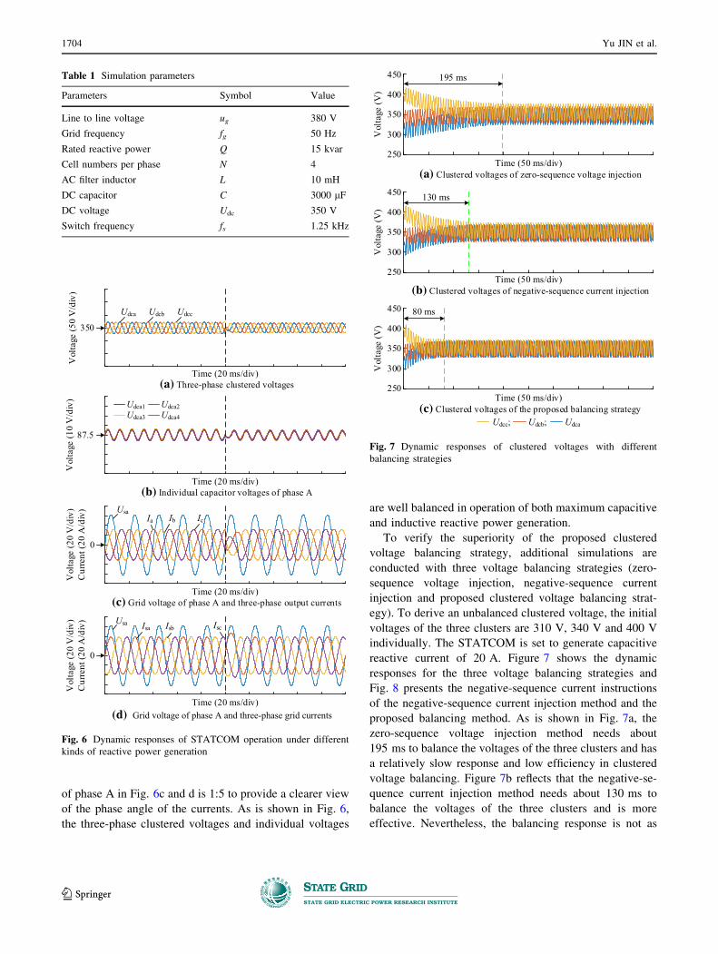
of phase A in Fig. 6c and d is 1:5 to provide a clearer view
of the phase angle of the currents. As is shown in Fig. 6,
the three-phase clustered voltages and individual voltages
are well balanced in operation of both maximum capacitive
and inductive reactive power generation.
To verify the superiority of the proposed clustered
voltage balancing strategy, additional simulations are
conducted with three voltage balancing strategies (zero-
sequence voltage injection, negative-sequence current
injection and proposed clustered voltage balancing strat-
egy). To derive an unbalanced clustered voltage, the initial
voltages of the three clusters are 310 V, 340 V and 400 V
individually. The STATCOM is set to generate capacitive
reactive current of 20 A. Figure 7 shows the dynamic
responses for the three voltage balancing strategies and
Fig. 8 presents the negative-sequence current instructions
of the negative-sequence current injection method and the
proposed balancing method. As is shown in Fig. 7a, the
zero-sequence voltage injection method needs about
195 ms to balance the voltages of the three clusters and has
a relatively slow response and low efficiency in clustered
voltage balancing. Figure 7b reflects that the negative-se-
quence current injection method needs about 130 ms to
balance the voltages of the three clusters and is more
effective. Nevertheless, the balancing response is not as
Table 1 Simulation parameters
Parameters Symbol Value
Line to line voltage ug 380 V
Grid frequency fg 50 Hz
Rated reactive power Q 15 kvar
Cell numbers per phase N 4
AC filter inductor L 10 mH
DC capacitor C 3000 lF
DC voltage Udc 350 V
Switch frequency fs 1.25 kHz
Time (20 ms/div)
Vol
tage
(50
V/d
iv)
350
(a) Three-phase clustered voltages
Udca1 Udca2Udca3 Udca4
87.5
Vol
tage
(10
V/d
iv)
Time (20 ms/div)(b) Individual capacitor voltages of phase A
0
Ia Ib IcUsa
Vol
tage
(20
V/d
iv)
Cur
rent
(20
A/d
iv)
Time (20 ms/div)(c) Grid voltage of phase A and three-phase output currents
Usa Isb IscIsa
0
Vol
tage
(20
V/d
iv)
Cur
rent
(20
A/d
iv)
Time (20 ms/div)
Udca UdccUdcb
(d) Grid voltage of phase A and three-phase grid currents
Fig. 6 Dynamic responses of STATCOM operation under different
kinds of reactive power generation
Time (50 ms/div)
Vol
tage
(V)
350
(a) Clustered voltages of zero-sequence voltage injection
Vol
tage
(V)
Time (50 ms/div)(b) Clustered voltages of negative-sequence current injection
Time (50 ms/div)(c) Clustered voltages of the proposed balancing strategy
195 ms
300
400
450
250
130 ms
350
300
400
450
250
80 ms
UdcaUdcb;Udcc;
Vol
tage
(V)
350
300
400
450
250
Fig. 7 Dynamic responses of clustered voltages with different
balancing strategies
1704 Yu JIN et al.
123
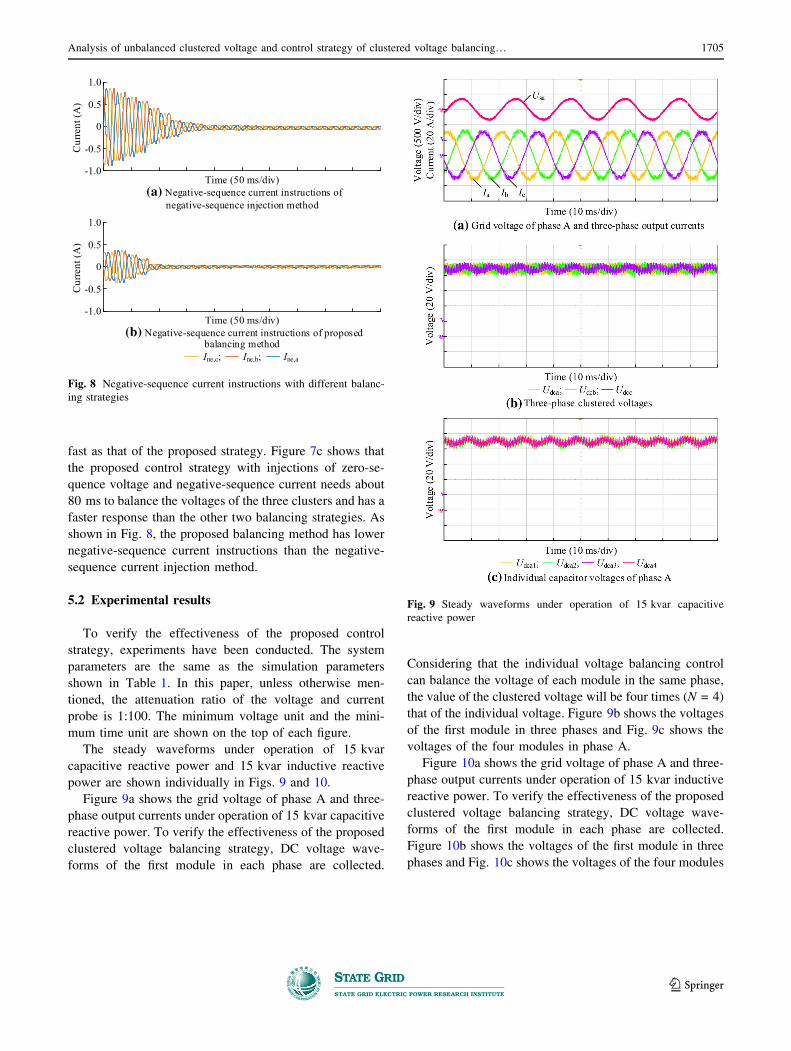
fast as that of the proposed strategy. Figure 7c shows that
the proposed control strategy with injections of zero-se-
quence voltage and negative-sequence current needs about
80 ms to balance the voltages of the three clusters and has a
faster response than the other two balancing strategies. As
shown in Fig. 8, the proposed balancing method has lower
negative-sequence current instructions than the negative-
sequence current injection method.
5.2 Experimental results
To verify the effectiveness of the proposed control
strategy, experiments have been conducted. The system
parameters are the same as the simulation parameters
shown in Table 1. In this paper, unless otherwise men-
tioned, the attenuation ratio of the voltage and current
probe is 1:100. The minimum voltage unit and the mini-
mum time unit are shown on the top of each figure.
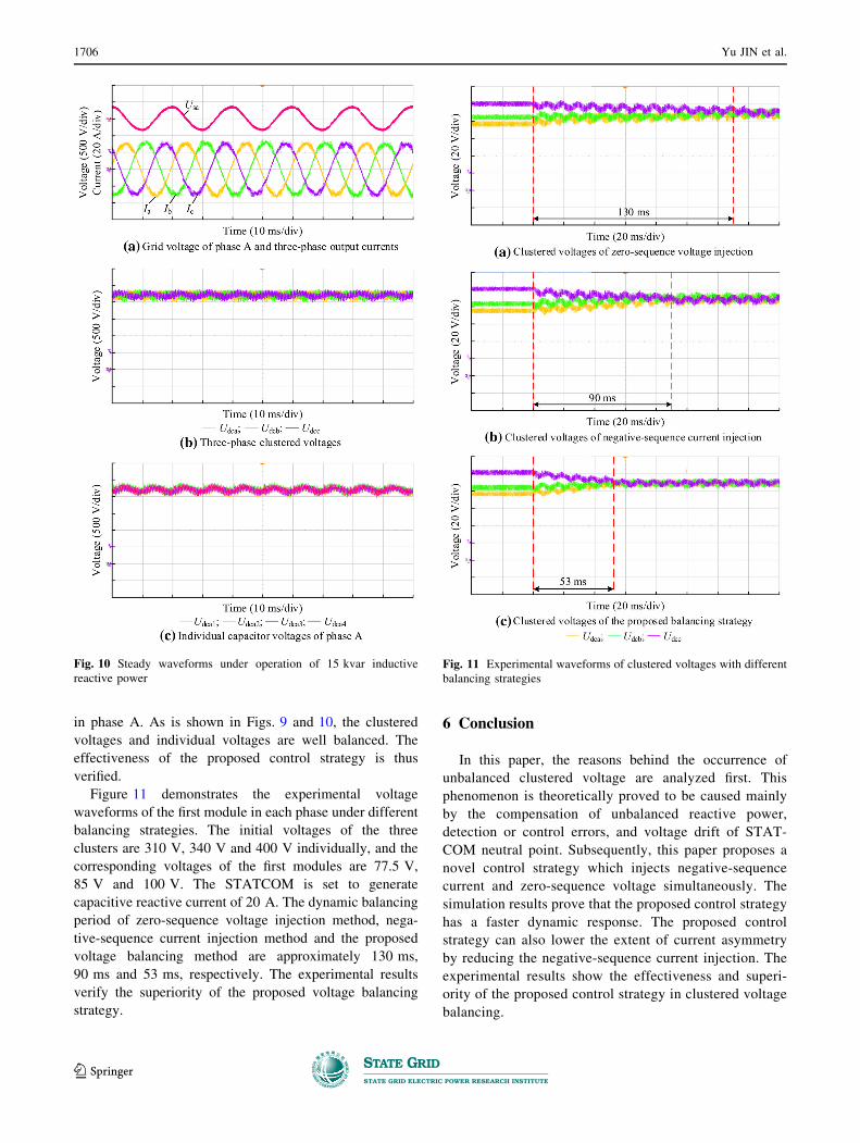
The steady waveforms under operation of 15 kvar
capacitive reactive power and 15 kvar inductive reactive
power are shown individually in Figs. 9 and 10.
Figure 9a shows the grid voltage of phase A and three-
phase output currents under operation of 15 kvar capacitive
reactive power. To verify the effectiveness of the proposed
clustered voltage balancing strategy, DC voltage wave-
forms of the first module in each phase are collected.
Considering that the individual voltage balancing control
can balance the voltage of each module in the same phase,
the value of the clustered voltage will be four times (N = 4)
that of the individual voltage. Figure 9b shows the voltages
of the first module in three phases and Fig. 9c shows the
voltages of the four modules in phase A.
Figure 10a shows the grid voltage of phase A and three-
phase output currents under operation of 15 kvar inductive
reactive power. To verify the effectiveness of the proposed
clustered voltage balancing strategy, DC voltage wave-
forms of the first module in each phase are collected.
Figure 10b shows the voltages of the first module in three
phases and Fig. 10c shows the voltages of the four modules
Fig. 9 Steady waveforms under operation of 15 kvar capacitive
reactive power
Cur
rent
(A)
Time (50 ms/div)(a) Negative-sequence current instructions of
negative-sequence injection method
Time (50 ms/div)(b) Negative-sequence current instructions of proposed
balancing method
0
-0.5
0.5
1.0
-1.0
Ine,aIne,b;Ine,c;
Cur
rent
(A)
0
-0.5
0.5
1.0
-1.0
Fig. 8 Negative-sequence current instructions with different balanc-
ing strategies
Analysis of unbalanced clustered voltage and control strategy of clustered voltage balancing… 1705
123
in phase A. As is shown in Figs. 9 and 10, the clustered
voltages and individual voltages are well balanced. The
effectiveness of the proposed control strategy is thus
verified.
Figure 11 demonstrates the experimental voltage
waveforms of the first module in each phase under different
balancing strategies. The initial voltages of the three
clusters are 310 V, 340 V and 400 V individually, and the
corresponding voltages of the first modules are 77.5 V,
85 V and 100 V. The STATCOM is set to generate
capacitive reactive current of 20 A. The dynamic balancing
period of zero-sequence voltage injection method, nega-
tive-sequence current injection method and the proposed
voltage balancing method are approximately 130 ms,
90 ms and 53 ms, respectively. The experimental results
verify the superiority of the proposed voltage balancing
strategy.
6 Conclusion
In this paper, the reasons behind the occurrence of
unbalanced clustered voltage are analyzed first. This
phenomenon is theoretically proved to be caused mainly
by the compensation of unbalanced reactive power,
detection or control errors, and voltage drift of STAT-
COM neutral point. Subsequently, this paper proposes a
novel control strategy which injects negative-sequence
current and zero-sequence voltage simultaneously. The
simulation results prove that the proposed control strategy
has a faster dynamic response. The proposed control
strategy can also lower the extent of current asymmetry
by reducing the negative-sequence current injection. The
experimental results show the effectiveness and superi-
ority of the proposed control strategy in clustered voltage
balancing.
Fig. 11 Experimental waveforms of clustered voltages with different
balancing strategies
Fig. 10 Steady waveforms under operation of 15 kvar inductive
reactive power
1706 Yu JIN et al.
123

Open Access This article is distributed under the terms of the
Creative Commons Attribution 4.0 International License (http://
creativecommons.org/licenses/by/4.0/), which permits unrestricted
use, distribution, and reproduction in any medium, provided you give
appropriate credit to the original author(s) and the source, provide a
link to the Creative Commons license, and indicate if changes were
made.
References
[1] Lu D, Wang J, Yao J et al (2017) Clustered voltage balancing
mechanism and its control strategy for star-connected cascaded
h-bridge statcom. IEEE Trans Ind Electron 64(10):7623–7633
[2] Reddy CL, Kumar PS, Sushama M et al (2015) A five level
cascaded H-bridge multilevel STATCOM. In: Proceedings of
IEEE Asia Pacific conference on postgraduate research in
microelectronics and electronics, Hyderabad, India, 27–29
November 2015, 6 pp
[3] Hu Y, Ren J, Wang J et al (2011) Analysis of voltage unbalance
phenomenon and causes in cluster DC link of cascaded H-bridge
STATCOM. Automat Electr Power Syst 35(21):96–100
[4] Akagi H, Inoue S, Yoshii T (2007) Control and performance of
a transformerless cascade PWM STATCOM with star configu-
ration. IEEE Trans Ind Appl 43(4):1041–1049
[5] Zhao L, Shi YJ, Duan SX et al (2009) The research of DC
capacitance voltages balancing strategy based on cascade
STATCOM using individual phase instantaneous current
tracking. In: Proceedings of IEEE international power elec-
tronics and motion control conference, Wuhan, China, 17–20
May 2009, 5 pp
[6] Xu R, Yu Y, Yang R et al (2014) A novel control method for
individual DC voltage balancing in H-bridge cascaded STAT-
COM. In: Proceedings of international power electronics con-
ference, Hiroshima, Japan, 18–21 May 2014, 5 pp
[7] Neyshabouri Y, Iman-Eini H, Farhangi S (2013) Control of a
transformer-less cascaded H-bridge based STATCOM using
low-frequency selective harmonic elimination technique. In:
Proceedings of international conference on environment and
electrical engineering, Wroclaw, Poland, 5–8 May 2013, 6 pp
[8] Neyshabouri Y, Iman-Eini H, Miranbeigi M (2015) State
feedback control strategy and voltage balancing scheme for a
transformer-less Stati synchronous compensator based on cas-
caded H-bridge converter. Power Electron IET 8(6):906–917
[9] Barrena JA, Marroyo L, Vidal MAR et al (2008) Individual
voltage balancing strategy for PWM cascaded H-bridge con-
verter-based STATCOM. IEEE Trans Ind Electron 55(1):21–29
[10] Marzoughi A, Neyshabouri Y, Imaneini H (2014) Control
scheme for cascaded H-bridge converter-based distribution
network static compensator. Power Electron IET
7(11):2837–2845
[11] Lei E, Yin X, Zhang Z et al (2018) An improved transformer
winding tap injection DSTATCOM topology for medium-volt-
age reactive power compensation. IEEE Trans Power Electron
33(3):2113–2126
[12] Sun Y, Zhao J, Ji Z et al (2013) An improved DC capacitor
voltage balancing strategy for PWM cascaded H-bridge con-
verter-based STATCOM. In: Proceedings of international con-
ference on power electronics and drive systems, Kitakyushu,
Japan, 22–25 April 2013, 6 pp
[13] Guo S, Liu D (2010) Voltage oriented based control strategy for
cascaded PWM STATCOM. In: Proceedings of Asia-Pacific
power and energy engineering conference, Chengdu, China,
28–31 March 2010, 4 pp
[14] Townsend CD, Cox SM, Watson AJ et al (2012) Voltage bal-
ancing characteristics for a cascaded H-bridge multi-level
STATCOM employing space vector modulation. Novi Sad,
Serbia, 4–6 September 2012, 7 pp
[15] Su Z, Zeng G, Zhang J et al (2012) The DC capacitors’ voltage
balancing strategy for cascaded H-bridge converter based
STATCOM. In: Proceedings of IEEE international power
electronics and motion control conference, Harbin, China, 2–5
June 2012, 4 pp
[16] Behrouzian E, Bongiorno M, Teodorescu R et al (2015) Indi-
vidual capacitor voltage balancing in H-bridge cascaded mul-
tilevel STATCOM at zero current operating mode. In:
Proceedings of European conference on power electronics and
applications, Geneva, Switzerland, 8–10 September 2015, 10 pp
[17] Maharjan L, Inoue S, Akagi H (2008) A transformerless energy
storage system based on a cascade multilevel PWM converter
with star configuration. IEEE Trans Ind Appl 44(5):1621–1630
[18] Maharjan L, Yamagishi T, Akagi H (2012) Active-power con-
trol of individual converter cells for a battery energy storage
system based on a multilevel cascade PWM converter. IEEE
Trans Power Electron 27(3):1099–1107
[19] Hatano N, Ise T (2010) Control scheme of cascaded H-bridge
STATCOM using zero-sequence voltage and negative-sequence
current. IEEE Trans Power Deliv 25(2):543–550
[20] Chen HC, Cheng PT (2015) Improved DC voltage utilization for
the star-connected cascaded H-bridges converter under unbal-
anced voltage sags. In: Proceedings of 9th international con-
ference on power electronics and ECCE Asia, Seoul, South
Korea, 1–5 June 2015, 8 pp
[21] Chen HC, Cheng PT (2017) A DC bus voltage balancing
technique for the cascaded H-bridge STATCOM with improved
reliability under grid faults. IEEE Trans Ind Appl
53(2):1263–1270
[22] Han C, Huang AQ, Liu Y et al (2007) A generalized control
strategy of per-phase DC voltage balancing for cascaded mul-
tilevel converter based STATCOM. In: Proceedings of IEEE
power electronics specialists conference, Orlando, USA, 17–21
June 2007, 7 pp
[23] Lee C, Chen H, Wang C et al (2014) A flexible DC voltage
balancing control based on the power flow management for star-
connected cascaded H-bridge converter. In: Proceedings of
IEEE energy conversion congress and exposition, Pittsburgh,
USA, 14–18 September 2014, 8 pp
Yu JIN received B.S. degree from School of Electrical Engineering
and Automation, Harbin Institute of Technology, Harbin, China. He is
currently working as a Ph.D. student in School of Electrical
Engineering and Automation, Harbin Institute of Technology. His
research interests include control method and applications of Half/
Full bridge modular multilevel converter including STATCOM,
motor driver, MMC-based energy storage system.
Jianze WANG received the B.E., M.E., and Ph.D. degrees in
Electrical Engineering from the Harbin Institute of Technology,
Harbin, China, in 1993, 1996, and 1999, respectively. He joined the
Harbin Institute of Technology, in 1999, and is currently a Research
Professor. From July 2003 to December 2003, he was a Visiting
Scholar with the Hong Kong Polytechnic University, Hong Kong,
China. His current research interests include power electronics,
multilevel converters, and digital-signal-processor-based power qual-
ity control systems.
Yiqi LIU received the B.S. degree in Electrical Engineering from
Northeast Agriculture University, Harbin, China, in 2009, the M.S.
Analysis of unbalanced clustered voltage and control strategy of clustered voltage balancing… 1707
123

degree in Electrical Engineering from the Tianjin University of
Technology, Tianjin, China, in 2012, and the Ph.D. degree in
electrical engineering from the Harbin Institute of Technology,
Harbin, China, in 2016. He joined Northeast Forestry University,
Harbin, China, in 2016, where he is currently an Associate Professor.
His current research interests include power electronics for renewable
energy sources, multilevel converters, high-voltage direct-current
technology, and microgrid clusters.
Xiangyu SAI received B.S. degree from School of Electrical
Engineering and Automation, Harbin Institute of Technology, Harbin.
He is a M.S. candidate of Electrical Engineering and Automation at
Harbin Institute of Technology. His research interests include the
control strategy and applications of active power filters, battery’s
SOC in large-capacity energy storage system.
Yanchao JI received the B.E., and M.E. degrees in Electrical
Engineering from Northeast Electric Power University, Jilin, China,
in 1983 and 1989, respectively, and the Ph.D. degree in Electrical
Engineering from the North China Electric Power University, Beijing,
China, in 1993. He joined the Department of Electrical Engineering,
Harbin Institute of Technology, Harbin, China in 1993. From 1995 to
1996, he was an Associate Professor with the Department of
Electrical Engineering, Harbin Institute of Technology, where he is
currently a Professor. His current research interests include pulse
width modulation technique, power converter, and flexible AC
transmission systems devices.
1708 Yu JIN et al.
123