Embed Size (px)
Citation preview
Acta of Bioengineering and Biomechanics Original paperVol. 13, No. 1, 2011
Analysis of wall shear stress around a competitive swimmerusing 3D Navier–Stokes equations in CFD
C.V. POPAa*, H. ZAIDI a, A. ARFAOUI a, G. POLIDORIa, R. TAIARb, S. FOHANNOa
a GRESPI/Thermomécanique, Université de Reims Champagne-Ardenne, Reims, France.b Laboratoire d’Analyse des Contraintes Mécaniques, Université de Reims Champagne-Ardenne, Reims, France.
This paper deals with the flow dynamics around a competitive swimmer during underwater glide phases occurring at the start and atevery turn. The influence of the head position, namely lifted up, aligned and lowered, on the wall shear stress and the static pressuredistributions is analyzed. The problem is considered as 3D and in steady hydrodynamic state. Three velocities (1.4 m/s, 2.2 m/s and3.1 m/s) that correspond to inter-regional, national and international swimming levels are studied. The flow around the swimmer is as-sumed turbulent. The Reynolds-averaged Navier–Stokes (RANS) equations are solved with the standard k–ω turbulent model by usingthe CFD (computational fluid dynamics) numerical method based on a volume control approach. Numerical simulations are carried outwith the ANSYS FLUENT® CFD code. The results show that the wall shear stress increases with the velocity and consequently the dragforce opposing the movement of the swimmer increases as well. Also, high wall shear stresses are observed in the areas where the bodyshape, globally rigid in form, presents complex surface geometries such as the head, shoulders, buttocks, heel and chest.
Key words: swimmer, wall shear stress, static pressure, standard k–ω turbulence model, CFD
1. Introduction
The glide phase, which plays a significant role dur-ing swimming starts and turns, is one of the most im-portant elements in swimming races as it allows thewave drag effects to be avoided. It is the reason why theFINA rules impose a 15 m limit on underwater swim-ming phases. The hydrodynamic performance in swim-ming depends greatly on the technique adopted by theswimmers during the different phases of swimming aswell as on the drag force opposing their movements inwater. Moreover, it is known (NAEMI et al. [14],BIXLER and RIEWALD [10]) that the drag force greatlydepends on pressure and wall shear stress fields aroundthe swimmer. So, improving the performance requiresa better understanding of the flow behaviour aroundswimmers (pressure field and wall shear stress distri-bution) in order to minimize the drag force.
Several authors carried out measurements of thedrag acting on the whole body of the swimmer andestimated the influence of various parameters such asthe swimmer’s position, morphology or velocity onthe intensity of the drag ([1]–[5]). In the biomechanicsof swimming, concerning both fishes and humanswimmers, the computational fluid dynamics (CFD)has been extensively used for last years due to thecomplexity of the experiments and the development ofcomputers (ADKINS and YAN [6], KATO et al. [7],SATO and HINO [8], MARINHO et al. [9]). BIXLER andRIEWALD [10] first used the CFD method to simulatethe water flow around a swimmer’s hand and forearm.The aim of their study was to calculate the drag forcesand their coefficients around a swimmer’s hand andforearm in the case of different angles of attack.ROUBOA et al. [11] estimated numerically the dragand lift coefficients for a swimmer’s hand and forearmin both the steady and unsteady state cases. They also
______________________________
* Corresponding author: C.V. Popa, GRESPI/Thermomécanique, Université de Reims Champagne-Ardenne, Moulin de la Housse,BP 1039, 51687 Reims, France. Tel. +33326913278. E-mail: [email protected]
Received: June 26th, 2010Accepted for publication: January 9th, 2011
C.V. POPA et al.4
evaluated the effect of the acceleration of the handand forearm on the generation of the propulsive force.GARDANO and DABNICHKI [12] performed numericalsimulations in order to highlight the importance of theanalysis of flow around the whole arm of a swimmer,so that the exact values of the propulsion and the dragforces were estimated. BIXLER et al. [13] used theCFD method to estimate the drag forces encounteredby the swimmer during the underwater glide phaseand to study the effect of wearing a wetsuit on thedrag forces. More recently, the numerical results ob-tained by ZAÏDI et al. [15] in a 2D geometry case re-vealed that the position of the head had a noticeableeffect on the hydrodynamic performances in under-water phase of start and turn. The analysis of theseresults made it possible to propose an optimal positionof the swimmer’s head in underwater glide swimming.Five turbulence models were tested by ZAÏDI et al.[16] in a 2D configuration and steady hydrodynamicstate. The comparison between these models and ex-perimental results reveals that the standard k–ω turbu-lence model is the most appropriate to predict the flowaround the swimmer. More recently, ZAÏDI et al. [17]studied a 3D geometry using a CFD code. Two turbu-lence models were tested, namely the standard k–εturbulence model and the standard k–ω turbulenceone, in order to predict drag forces during the under-water glide phases. The comparison between numericalresults and experimental measurements of drag forcesshows that the standard k–ω model accurately predictsthe drag forces while the standard k–ε model underes-timates their values. By making the assumption that theswimmer can adopt a rigid posture of the body, it canbe expected that in a laminar turbulent transition Reapproaches 5×10⁵. This implies that the flow aroundthe swimmer is mainly turbulent [17]–[20].
The objective of this paper was to study the flowdynamics around the swimmer during underwaterglide phases in swimming. Three velocities (U0 = 1.4,2.2 and 3.1 m/s) corresponding to the following rangeof the Reynolds number 4×10⁶ ≤ Re ≤ 9×10⁶ (ZAÏDI etal. [16]) were studied. These values correspond to thevelocity at the time of the departure (underwater glidephase after start dive) from inter-regional, nationaland international swimming levels (TOUSSAINT et al.[3]). Also, the influence of the head position, namelylifted up, aligned and lowered, on the wall shear stressand static pressure distributions were analyzed. To theauthors’ knowledge, this study is the first investiga-tion of the pressure field and wall shear stress distri-bution around the whole swimmer’s body. Three glidepositions were investigated, depending on whether thehead is aligned with the body, lifted up or lowered.
2. Material and methods
2.1. Geometry and mesh
The construction of the 3D geometric model of theswimmer follows the same procedure as that de-scribed by ZAÏDI et al. [17]. The subject chosen for thepresent study is a national-level male swimmer. Theequipment used in the construction of his 3D geomet-ric model is a Konica Minolta® scanner, which iscommanded by a laser scanning process. The scannerallows the creation of data files containing all the co-ordinates of all the points defining the layer on thesurface of the swimmer’s body. The RapidForm®
software has been used in the construction of theswimmer’s geometry using the data file that containsthe clouds of points coming from the scanner.
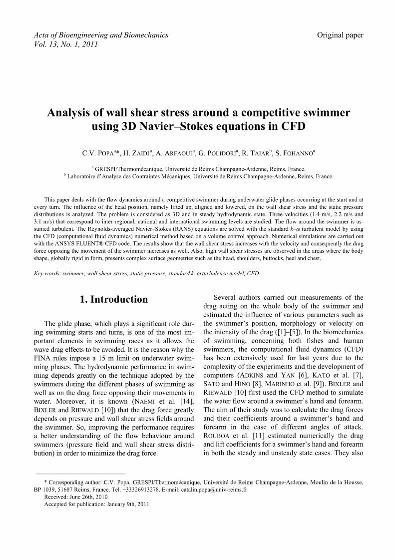
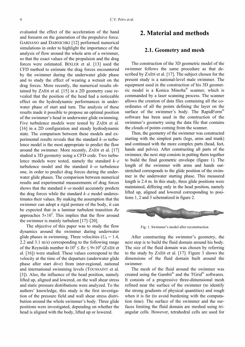
Then, the geometry of the swimmer was constructedstarting with the simplest parts (legs, arms and trunk)and continued with the more complex parts (head, feet,hands and pelvis). After constructing all parts of theswimmer, the next step consists in putting them togetherto build the final geometric envelope (figure 1). Thelength of the swimmer with arms and hands out-stretched corresponds to the glide position of the swim-mer in the underwater starting phase. This measuredlength is 2.4 m. In this study, three glide positions weremaintained, differing only in the head position, namelylifted up, aligned and lowered corresponding to posi-tions 1, 2 and 3 schematized in figure 2.
Fig. 1. Swimmer’s model after reconstruction
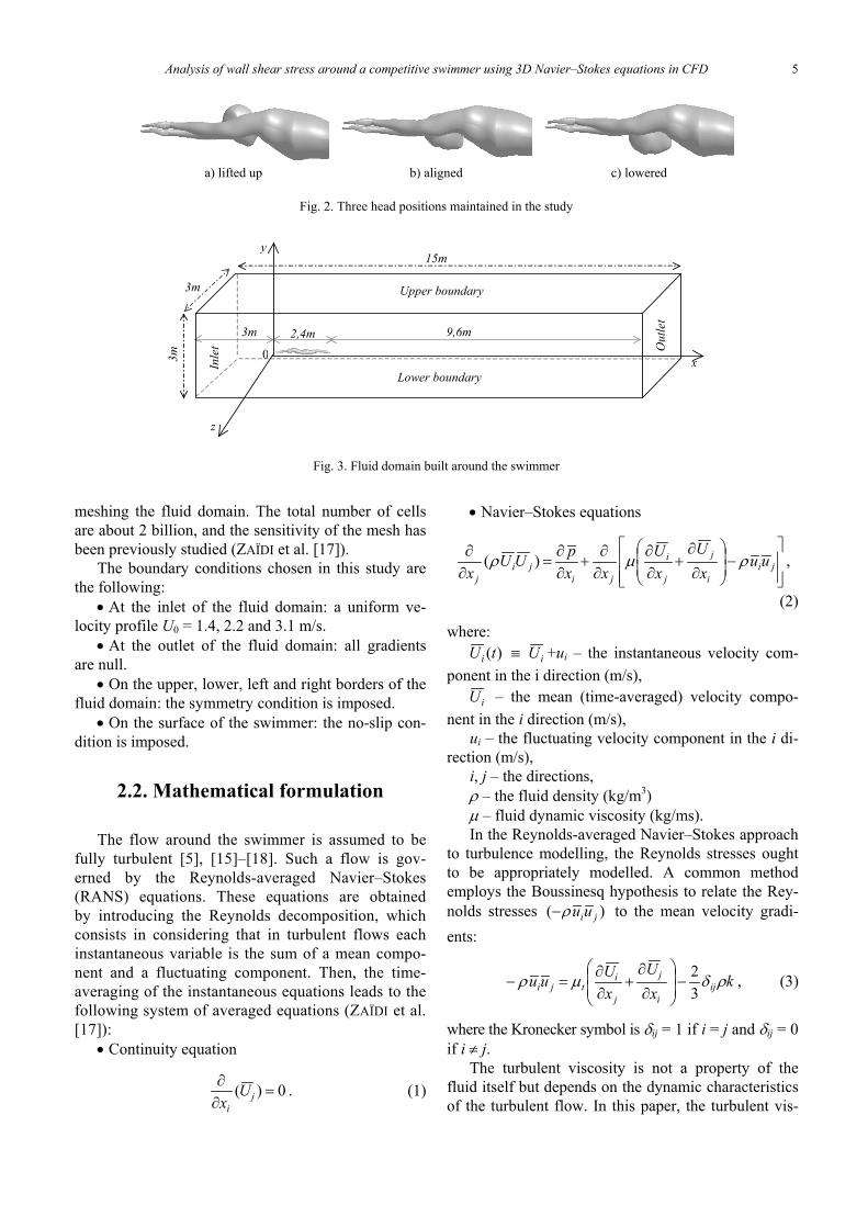
After constructing the swimmer’s geometry, thenext step is to build the fluid domain around his body.The size of the fluid domain was chosen by referringto the study by ZAÏDI et al. [17]. Figure 3 shows thedimensions of the fluid domain built around theswimmer.
The mesh of the fluid around the swimmer wascreated using the Gambit® and the TGrid® softwares.It consists of a progressive three-dimensional meshrefined near the surface of the swimmer (to identifythe strong gradients of physical quantities) and roughwhen it is far (to avoid burdening with the computa-tion time). The surface of the swimmer and the sur-faces limiting the fluid domain are meshed using tri-angular cells. However, tetrahedral cells are used for
Analysis of wall shear stress around a competitive swimmer using 3D Navier–Stokes equations in CFD 5
meshing the fluid domain. The total number of cellsare about 2 billion, and the sensitivity of the mesh hasbeen previously studied (ZAÏDI et al. [17]).
The boundary conditions chosen in this study arethe following:
• At the inlet of the fluid domain: a uniform ve-locity profile U0 = 1.4, 2.2 and 3.1 m/s.
• At the outlet of the fluid domain: all gradientsare null.
• On the upper, lower, left and right borders of thefluid domain: the symmetry condition is imposed.
• On the surface of the swimmer: the no-slip con-dition is imposed.
2.2. Mathematical formulation
The flow around the swimmer is assumed to befully turbulent [5], [15]–[18]. Such a flow is gov-erned by the Reynolds-averaged Navier–Stokes(RANS) equations. These equations are obtainedby introducing the Reynolds decomposition, whichconsists in considering that in turbulent flows eachinstantaneous variable is the sum of a mean compo-nent and a fluctuating component. Then, the time-averaging of the instantaneous equations leads to thefollowing system of averaged equations (ZAÏDI et al.[17]):
• Continuity equation
0)( =∂∂
ji
Ux
. (1)
• Navier–Stokes equations
⎥⎥⎦
⎤
⎢⎢⎣
⎡−⎟
⎟⎠
⎞⎜⎜⎝
⎛
∂∂
+∂∂
∂∂
+∂∂
=∂∂
jii
j
j
i
jiji
juu
xU
xU
xxpUU
xρμρ )( ,
(2)
where:)(tUi ≡ iU +ui – the instantaneous velocity com-
ponent in the i direction (m/s),iU – the mean (time-averaged) velocity compo-
nent in the i direction (m/s),ui – the fluctuating velocity component in the i di-
rection (m/s),i, j – the directions,ρ – the fluid density (kg/m3)μ – fluid dynamic viscosity (kg/ms).In the Reynolds-averaged Navier–Stokes approach
to turbulence modelling, the Reynolds stresses oughtto be appropriately modelled. A common methodemploys the Boussinesq hypothesis to relate the Rey-nolds stresses )( jiuuρ− to the mean velocity gradi-ents:
kx
UxUuu ij
i
j
j
itji ρδμρ
32
−⎟⎟⎠
⎞⎜⎜⎝
⎛
∂∂
+∂∂
=− , (3)
where the Kronecker symbol is δij = 1 if i = j and δij = 0if i ≠ j.
The turbulent viscosity is not a property of thefluid itself but depends on the dynamic characteristicsof the turbulent flow. In this paper, the turbulent vis-
a) lifted up b) aligned c) lowered
Fig. 2. Three head positions maintained in the study
Upper boundary
Lower boundary
Inle
t Out
let
z
y
x03m
3m
15m
3m 2,4m 9,6m
Fig. 3. Fluid domain built around the swimmer
C.V. POPA et al.6
cosity is modelled by means of the first-order modelsbased on the time-averaged dynamical characteristicsof the turbulent flow. The standard k–ω model waschosen because it is well suited to wall-bounded flowslike the flow around the body contour of the swimmer(ZAÏDI et al. [17]). The standard k–ω turbulencemodel is an empirical model based on transport equa-tions for the turbulent kinetic energy per unit mass (k)and the specific dissipation rate (ω). Two additionaltransport equations for the turbulent kinetic energy perunit mass (k) and the specific dissipation rate (ω) aresolved. These equations are:
kkj
kj
jj
YPxkΓ
xUk
x−+⎟
⎟⎠
⎞⎜⎜⎝
⎛
∂∂
∂∂
=∂∂ )(ρ , (4)
ωωωωρω YPx
Γx
Ux jj
jj
−+⎟⎟⎠
⎞⎜⎜⎝
⎛
∂∂
∂∂
=∂∂ )( , (5)
where Yk and Yω are the turbulent dissipations of kand ω, respectively.
The effective diffusivities for k and ω are givenby:
k
tkΓ σ
μμ= , (6)
ωω σ
μμ tΓ = , (7)
where σk and σω are the turbulent Prandtl numbers fork and ω, respectively.
The turbulent viscosity (μt) is then calculated asthe function of k and ω :
ωραμ k
t*= , (8)
where α * is the coefficient allowing us to correct theturbulent viscosity at low Reynolds numbers.
The production of k and ω due to mean velocitygradients are:
i
jjik x
UuuP
∂∂
−= ρ , (9)
kPk
P ωαω = . (10)
2.3. Numerical method
The system of governing equations (1)–(5) withappropriate boundary conditions has been successfully
solved by using a numerical method, mainly based onthe volume control approach (PATANKAR [19]). Thismethod is based on the spatial integration of the con-servation equations over finite control volumes. Thenumerical simulations were carried out with theANSYS FLUENT® software. The convergence crite-ria were based on the residuals resulting from the in-tegration of the conservation equations (1)–(5) overfinite control volumes. During the iterative calculationprocess, these residuals were constantly monitoredand carefully examined. For all the simulations per-formed in this study, converged solutions were usuallyachieved with residuals as low as 10–5 (or less) for allthe governing equations.
3. Results and discussion
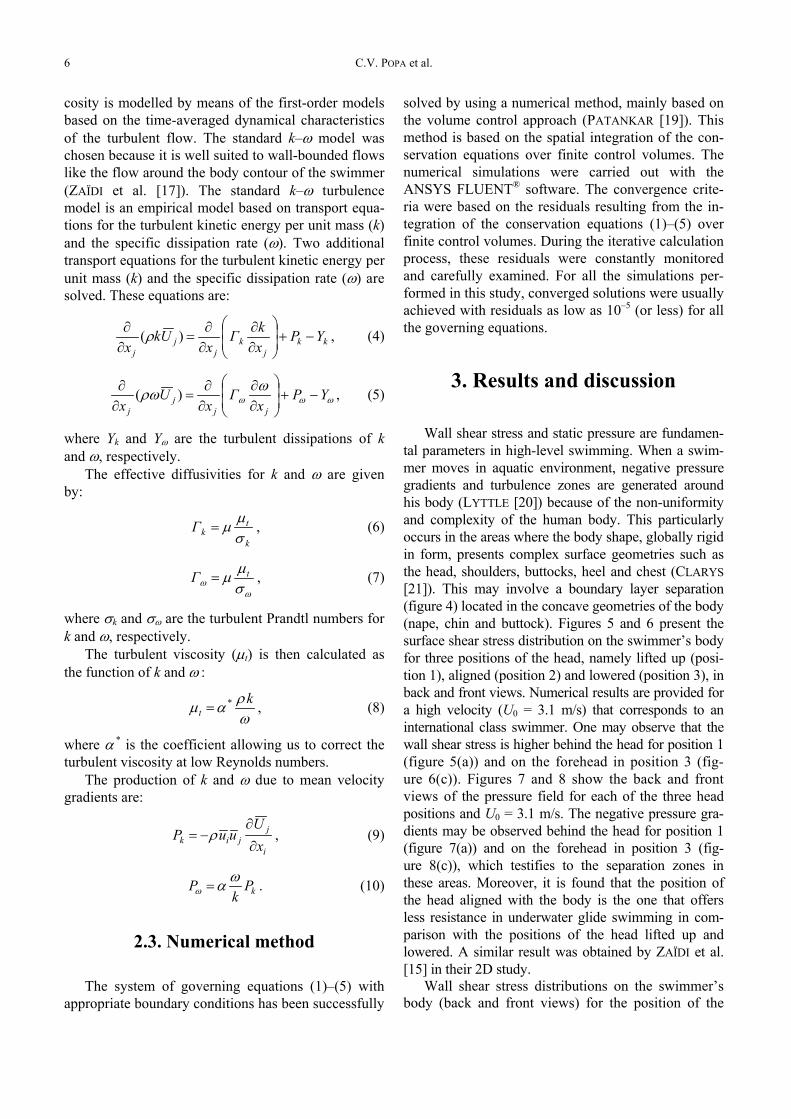
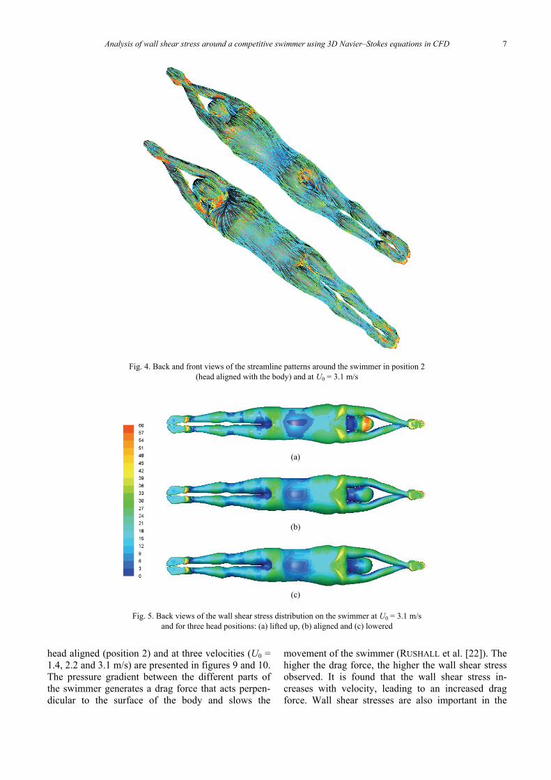
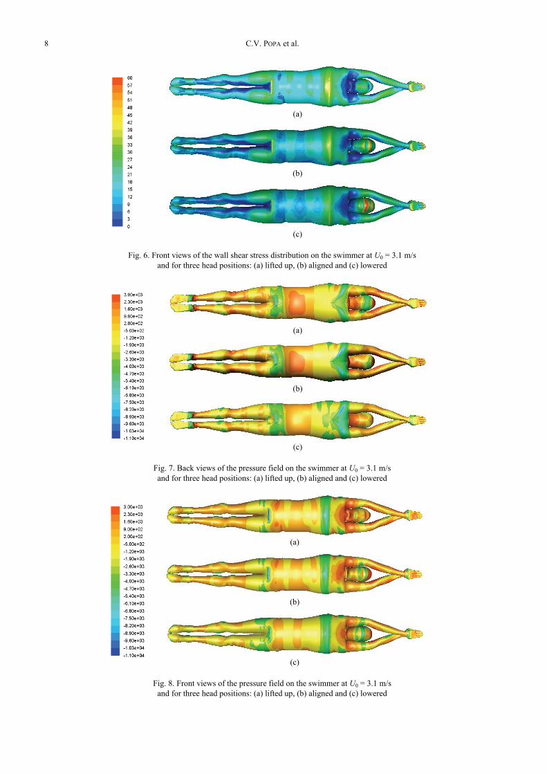
Wall shear stress and static pressure are fundamen-tal parameters in high-level swimming. When a swim-mer moves in aquatic environment, negative pressuregradients and turbulence zones are generated aroundhis body (LYTTLE [20]) because of the non-uniformityand complexity of the human body. This particularlyoccurs in the areas where the body shape, globally rigidin form, presents complex surface geometries such asthe head, shoulders, buttocks, heel and chest (CLARYS[21]). This may involve a boundary layer separation(figure 4) located in the concave geometries of the body(nape, chin and buttock). Figures 5 and 6 present thesurface shear stress distribution on the swimmer’s bodyfor three positions of the head, namely lifted up (posi-tion 1), aligned (position 2) and lowered (position 3), inback and front views. Numerical results are provided fora high velocity (U0 = 3.1 m/s) that corresponds to aninternational class swimmer. One may observe that thewall shear stress is higher behind the head for position 1(figure 5(a)) and on the forehead in position 3 (fig-ure 6(c)). Figures 7 and 8 show the back and frontviews of the pressure field for each of the three headpositions and U0 = 3.1 m/s. The negative pressure gra-dients may be observed behind the head for position 1(figure 7(a)) and on the forehead in position 3 (fig-ure 8(c)), which testifies to the separation zones inthese areas. Moreover, it is found that the position ofthe head aligned with the body is the one that offersless resistance in underwater glide swimming in com-parison with the positions of the head lifted up andlowered. A similar result was obtained by ZAÏDI et al.[15] in their 2D study.
Wall shear stress distributions on the swimmer’sbody (back and front views) for the position of the
Analysis of wall shear stress around a competitive swimmer using 3D Navier–Stokes equations in CFD 7
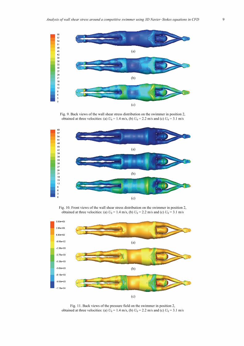
head aligned (position 2) and at three velocities (U0 =1.4, 2.2 and 3.1 m/s) are presented in figures 9 and 10.The pressure gradient between the different parts ofthe swimmer generates a drag force that acts perpen-dicular to the surface of the body and slows the
movement of the swimmer (RUSHALL et al. [22]). Thehigher the drag force, the higher the wall shear stressobserved. It is found that the wall shear stress in-creases with velocity, leading to an increased dragforce. Wall shear stresses are also important in the
Fig. 4. Back and front views of the streamline patterns around the swimmer in position 2(head aligned with the body) and at U0 = 3.1 m/s
(a)
(b)
(c)
Fig. 5. Back views of the wall shear stress distribution on the swimmer at U0 = 3.1 m/sand for three head positions: (a) lifted up, (b) aligned and (c) lowered
C.V. POPA et al.8
(a)
(b)
(c)
Fig. 6. Front views of the wall shear stress distribution on the swimmer at U0 = 3.1 m/sand for three head positions: (a) lifted up, (b) aligned and (c) lowered
(a)
(b)
(c)
Fig. 7. Back views of the pressure field on the swimmer at U0 = 3.1 m/sand for three head positions: (a) lifted up, (b) aligned and (c) lowered
(a)
(b)
(c)
Fig. 8. Front views of the pressure field on the swimmer at U0 = 3.1 m/sand for three head positions: (a) lifted up, (b) aligned and (c) lowered
Analysis of wall shear stress around a competitive swimmer using 3D Navier–Stokes equations in CFD 9
(a)
(b)
(c)
Fig. 9. Back views of the wall shear stress distribution on the swimmer in position 2,obtained at three velocities: (a) U0 = 1.4 m/s, (b) U0 = 2.2 m/s and (c) U0 = 3.1 m/s
(a)
(b)
(c)
Fig. 10. Front views of the wall shear stress distribution on the swimmer in position 2,obtained at three velocities: (a) U0 = 1.4 m/s, (b) U0 = 2.2 m/s and (c) U0 = 3.1 m/s
(a)
(b)
(c)
Fig. 11. Back views of the pressure field on the swimmer in position 2,obtained at three velocities: (a) U0 = 1.4 m/s, (b) U0 = 2.2 m/s and (c) U0 = 3.1 m/s
C.V. POPA et al.10
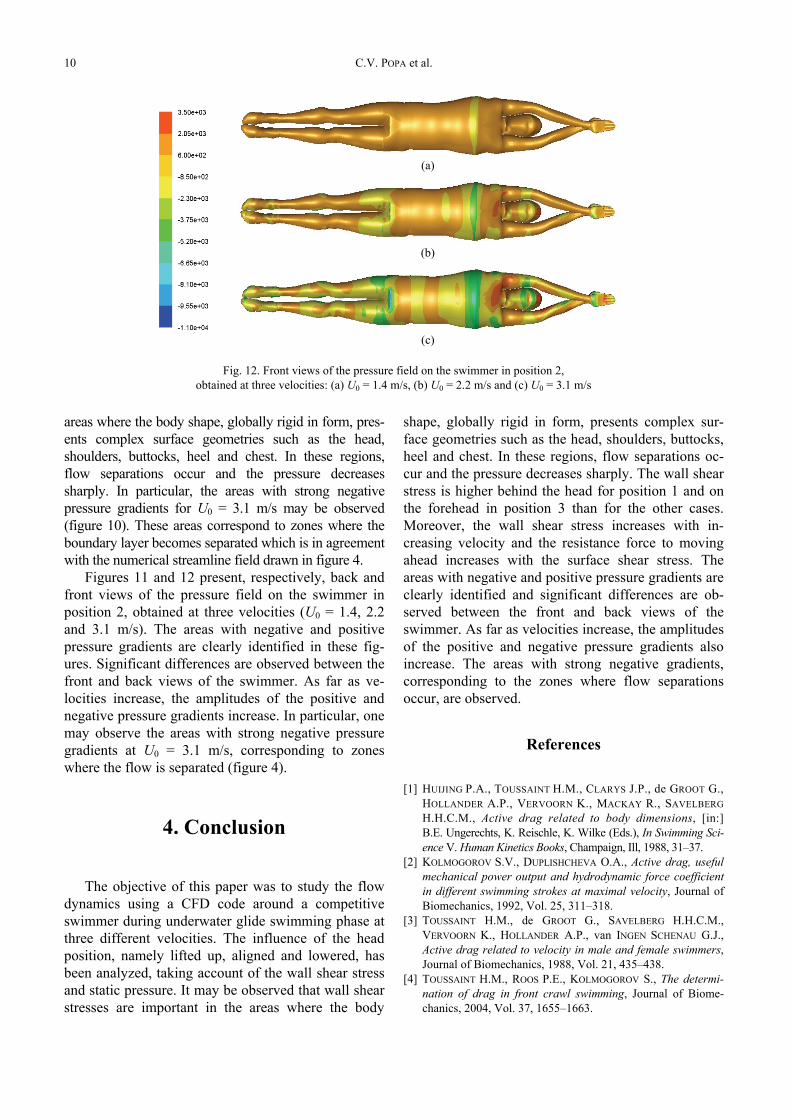
areas where the body shape, globally rigid in form, pres-ents complex surface geometries such as the head,shoulders, buttocks, heel and chest. In these regions,flow separations occur and the pressure decreasessharply. In particular, the areas with strong negativepressure gradients for U0 = 3.1 m/s may be observed(figure 10). These areas correspond to zones where theboundary layer becomes separated which is in agreementwith the numerical streamline field drawn in figure 4.
Figures 11 and 12 present, respectively, back andfront views of the pressure field on the swimmer inposition 2, obtained at three velocities (U0 = 1.4, 2.2and 3.1 m/s). The areas with negative and positivepressure gradients are clearly identified in these fig-ures. Significant differences are observed between thefront and back views of the swimmer. As far as ve-locities increase, the amplitudes of the positive andnegative pressure gradients increase. In particular, onemay observe the areas with strong negative pressuregradients at U0 = 3.1 m/s, corresponding to zoneswhere the flow is separated (figure 4).
4. Conclusion
The objective of this paper was to study the flowdynamics using a CFD code around a competitiveswimmer during underwater glide swimming phase atthree different velocities. The influence of the headposition, namely lifted up, aligned and lowered, hasbeen analyzed, taking account of the wall shear stressand static pressure. It may be observed that wall shearstresses are important in the areas where the body
shape, globally rigid in form, presents complex sur-face geometries such as the head, shoulders, buttocks,heel and chest. In these regions, flow separations oc-cur and the pressure decreases sharply. The wall shearstress is higher behind the head for position 1 and onthe forehead in position 3 than for the other cases.Moreover, the wall shear stress increases with in-creasing velocity and the resistance force to movingahead increases with the surface shear stress. Theareas with negative and positive pressure gradients areclearly identified and significant differences are ob-served between the front and back views of theswimmer. As far as velocities increase, the amplitudesof the positive and negative pressure gradients alsoincrease. The areas with strong negative gradients,corresponding to the zones where flow separationsoccur, are observed.
References
[1] HUIJING P.A., TOUSSAINT H.M., CLARYS J.P., de GROOT G.,HOLLANDER A.P., VERVOORN K., MACKAY R., SAVELBERGH.H.C.M., Active drag related to body dimensions, [in:]B.E. Ungerechts, K. Reischle, K. Wilke (Eds.), In Swimming Sci-ence V. Human Kinetics Books, Champaign, Ill, 1988, 31–37.
[2] KOLMOGOROV S.V., DUPLISHCHEVA O.A., Active drag, usefulmechanical power output and hydrodynamic force coefficientin different swimming strokes at maximal velocity, Journal ofBiomechanics, 1992, Vol. 25, 311–318.
[3] TOUSSAINT H.M., de GROOT G., SAVELBERG H.H.C.M.,VERVOORN K., HOLLANDER A.P., van INGEN SCHENAU G.J.,Active drag related to velocity in male and female swimmers,Journal of Biomechanics, 1988, Vol. 21, 435–438.
[4] TOUSSAINT H.M., ROOS P.E., KOLMOGOROV S., The determi-nation of drag in front crawl swimming, Journal of Biome-chanics, 2004, Vol. 37, 1655–1663.
(a)
(b)
(c)
Fig. 12. Front views of the pressure field on the swimmer in position 2,obtained at three velocities: (a) U0 = 1.4 m/s, (b) U0 = 2.2 m/s and (c) U0 = 3.1 m/s
Analysis of wall shear stress around a competitive swimmer using 3D Navier–Stokes equations in CFD 11
[5] TOUSSAINT H.M., TRUIJENS M., Biomechanical aspects ofpeak performance in human swimming, Journal of AnimalBiology, 2005, Vol. 25, 17–40.
[6] ADKINS D., YAN Y.Y., CFD Simulation of fish-like bodymoving in viscous liquid, Journal of Bionic Engineering,2006, Vol. 3(3), 147–153.
[7] KATO N., AYERS J., MORIKAWA H., Bio-mechanisms ofSwimming and Flying, Springer-Verlag, Tokyo, 2004.
[8] SATO Y., HINO T., CFD simulation of flows around a swim-mer in a prone glide position, Japanese Journal of Sciencesin Swimming and Water Exercise, 2010, Vol. 13, No. 1, 1–9.
[9] MARINHO D.A., BARBOSA T.M., KJENDLIE P.L.,MANTRIPRAGADA N., VILAS-BOAS J.P., MACHADO L.,ALVES F.B., ROUBOA A.I., SILVA A.J., Modelling Hydro-dynamic Drag in Swimming using Computational FluidDynamics, Computational Fluid Dynamics, Hyoung Woo Oh(Ed.), 2010, InTech, Available from: http://www.intechopen.com/articles/show/title/modelling-hydrodynamic-drag-in-swimming-using-computational-fluid-dynamics.
[10] BIXLER B., RIEWALD S., Analysis of swimmer’s hand andarm in steady flow conditions using computational fluid dy-namics, Journal of Biomechanics, 2002, Vol. 35, 713–717.
[11] ROUBOA A., SILVA A., LEAL L., ROCHA J., ALVES F., Theeffect of swimmer’s hand/forearm acceleration on propulsiveforces generation using computational fluid dynamics, Journalof Biomechanics, 2006, Vol. 39, 1239–1248.
[12] GARDANO P., DABNICHKI P., On hydrodynamics of drag andlift of the human arm, Journal of Biomechanics, 2006, Vol. 39,2767–2773.
[13] BIXLER B., PEASE D., FAIRHURST F., The accuracy ofcomputational fluid dynamics analysis of the passive drag
of a male swimmer, Sports Biomechanics, 2007, Vol. 6,81–98.
[14] NAEMI R., EASSON W.J., SANDERS R.H., Hydrodynamic glideefficiency in swimming, Journal of Science and Medicine inSport, 2010, 13(4), 444–451.
[15] ZAÏDI H., FOHANNO S., TAÏAR R., POLIDORI G., Analysis ofthe effect of swimmer’s head position on swimming perform-ance using computational fluid dynamics, Journal of Biome-chanics, 2008, Vol. 41, 1350–1358.
[16] ZAÏDI H., TAÏAR R., FOHANNO S., POLIDORI G., An evaluation ofturbulence models in CFD simulations of underwater swimming,Series on Biomechanics, 2009, Vol. 24, 1–5.
[17] ZAÏDI H., FOHANNO S., TAÏAR R., POLIDORI G., Turbulencemodels choice for the calculating of drag forces when usingCFD method, Journal of Biomechanics, 2010, Vol. 43, 405–411.
[18] POLIDORI G., TAÏAR R., FOHANNO S., MAI T.H. LODINI A.,Skin-friction drag analysis from the forced convection mod-eling in simplified underwater swimming, Journal of Biome-chanics, 2006, Vol. 39, 2535–2541.
[19] PATANKAR S.V., Numerical Heat Transfer and Fluid Flow,Hemisphere, New York, 1980.
[20] LYTTLE A.D., Hydrodynamics of the Human Body During theFreestyle Tumble Turn, PhD Thesis, The University of West-ern Australia, Nedlands, Australia, 1999.
[21] CLARYS J.P., Human morphology and hydrodynamics, [in:] J.Terauds & E.W. Bedingfield (Eds.), International Series onSports Science 8; Swimming III, 1979, 3–41. Baltimore,USA, University Park Press.
[22] RUSHALL B.S., HOLT L.E., SPRIGINGS E.J., CAPPAERT J.M., Are-evaluation of forces in swimming, Journal of SwimmingResearch, 1994, Vol. 10, 6–30.7