Embed Size (px)
Citation preview
ngineering 55 (2007) 83–92www.elsevier.com/locate/petrol
Journal of Petroleum Science and E
Analysis of wellbore instability in vertical, directional,and horizontal wells using field data
M.A. Mohiuddin, K. Khan, A. Abdulraheem ⁎, A. Al-Majed, M.R. Awal
Center for Petroleum and Minerals, Research Institute, King Fahd University of Petroleum and Minerals,P.O. Box # 755, Dhahran - 31261, Saudi Arabia
Received 18 April 2005; accepted 26 April 2006
Abstract
An old offshore field produced using vertical and directional wells is being redeveloped by drilling horizontal wells. Theexperience gained while drilling vertical and directional wells is not useful for drilling horizontal wells, as the failure rate is 1 in 3holes. Quantification of drilling problems in sixty wells show that majority are tight holes. Stuck pipes and hole pack offs are alsosignificant in number. The major loss of productivity is due to stuck pipes. A preliminary study of shale in sections where problemsoccur, show no chemical reactivity. Petrographic analysis confirmed the fissile and brittle nature of shale with presence of open,partially healed microfractures and partings. Rock mechanical simulation predicted the safe mud weight window for horizontalwells as 76–90 PCF, depending on azimuth. However, all the horizontal wells analyzed in this study were drilled using the samemud weight window. Therefore, field based parameters like initial mud weight used for drilling, mud weight increment andproblems per well were used to analyze wellbore instability, identify different instability mechanisms and design safe mud weightwindow for drilling horizontal wells. These parameters were used first on the drilling data of vertical wells to develop the procedurefor the analysis of wellbore instability and identify the mechanisms of instability. The developed procedure was then applied to thedrilling data of directional wells to show the dependence of mud weight on the inclination and azimuth of the well. Finally, theprocedure was applied to horizontal wells data along with the concept of critical washouts to infer the safe mud weight window as77–80 PCF in East–West and 82–85 PCF in North–South directions. The safe mud weight window is validated on another set ofdrilling data showing 90% success rate. The analysis confirms the existence of anisotropy in horizontal stresses and is extremelyuseful in cases where there is significant variation in mechanical properties of different layers of reservoir rock.© 2006 Elsevier B.V. All rights reserved.
Keywords: Wellbore instability; Drilling data analysis; Wellbore wall stabilization; Differential sticking; Mud invasion; Pore pressure penetration
1. Introduction
Wellbore instability manifests itself in different wayslike hole pack off, excessive reaming, overpull, torque
⁎ Corresponding author.E-mail addresses: [email protected] (M.A. Mohiuddin),
[email protected] (A. Abdulraheem).
0920-4105/$ - see front matter © 2006 Elsevier B.V. All rights reserved.doi:10.1016/j.petrol.2006.04.021
and drag, sometimes leading to stuck pipe that mayrequire plugging and side tracking. This requiresadditional time to drill a hole, driving up the cost ofreservoir development significantly. In case of offshorefields, loss of hole is more critical due to a limitednumber of holes that can be drilled from a platform.
Drilling an ingauge hole is an interplay of twofactors: uncontrollable and controllable. Uncontrollable
84 M.A. Mohiuddin et al. / Journal of Petroleum Science and Engineering 55 (2007) 83–92
factors are the earth stresses (horizontal and vertical),pore pressure, rock strength and rock chemistry.Controllable factors include mud weight, wellboreazimuth and inclination. A proper drilling programoptimizes the controllable factors with the knowledge ofuncontrollable factors. The controllable factors areheavily dependent on rock mechanical behavior ofrock. For example, it is well known in the rockmechanics literature that the change in mud weightwith the angle of inclination depends on the in-situstresses, if the rock anisotropy is negligible. If a normalstress regime is present, then the horizontal wells aremore susceptible to instabilities and hence the mostdifficult to drill. The mud weight control plays a crucialrole in instability management with the angle ofinclination. Unfortunately, drillers traditionally dependon empirically derived “Rules of Thumb” rather thanrock mechanic principles of rock stability and failure indesigning mud weight.
1.1. Literature review
Design of wells using principles of rock mechanics iswell reported in the literature (Wong et al., 1994; Moritaand Whitebay, 1994). A case study of designing ahorizontal well in Vlieland sand in the Dutch sector ofNorth Sea is reported by Fuh et al. (1991). The rockmechanical parameters such as in-situ stresses, strengthand pore pressure of the Vlieland sand and shale whichoverlies it were computed from the back analysis ofdrilling problems from previous eight vertical wellsdrilled in the area. A mud program was designed usingthese estimated parameters and a horizontal hole wasdrilled with few manageable instances of instability.
Drilling of overburden shales in offshore Nigeriaresulted in several problems of stuck pipes andsidetracks. A detailed rock mechanics study wasconducted to characterize the state of in-situ stress,rock strength, and formation pore pressure. Theseparameters were used to perform a geomechanicalsimulation and estimate safe mud weights. Use of thesemud weights led to a marked improvement in wellborestability (Lowrey and Ottesen, 1995).
Four wells drilled in Gulf of Suez and MediterraneanSea, offshore Egypt, were analyzed for wellboreinstability, to improve drilling performance in futurewells (Hassan et al., 1999). A suite of logs, includingDSI sonic, GR, and density were used as input toIMPACT-ELAN of Geoframe to predict rock strength,petrophysical properties, and safe mud weight windows.The weak shales in the overburden were failing due toinadequate wall support inspite of using oil based mud
(OBM). The simulation predicted higher mud weight foradequate wall support. Use of predicted higher mudweights during drilling improved the hole condition andrelated instabilities. Therefore, OBM used of to drillshaly sections should be checked for correct mudweight.
Saidin and Smith (2000) discussed wellbore insta-bility encountered when drilling through the Terengganushale (K-shale), Bekok field, Malaysia. Due to the timedependency of the observed instability cases, K-shalewas thought of as reactive and unstable due to shale–fluid interaction. Invert emulsion OBM was used to drillthe wells. This, however, resulted in severe formationdamage without any improvement in stability. Rockcharacterization and laboratory measurements of rock-mechanical properties indicated that K-shales had predo-minantly non-reactive weak clay. This informationhelped in improving the design of mud weight windowleading to successful completion of a new well. To mi-nimize differential sticking due to high mud weights,invert emulsion SBM was used.
In many cases, factors like magnitude of themaximum horizontal in-situ stress and variations inrock strength are not well known. These parameters areestimated using empirical or semi-empirical approaches.Under such circumstances, the safe mud weight windowpredicted using geomechanical simulation is often notrealistic. For such cases, drilling data accumulated fromprevious problematic wells can be used to predict safemud weight window. A brief review of studies using theabove mentioned approach is given in the followingparagraphs.
Santarelli et al. (1996) presented wellbore instabilityproblems occurring in a developed field in Italy. Theproblems were back analyzed with respect to the mudtypes, mud weights, azimuths, and stress regime. Moredrilling problems like reaming and stuck pipe occurredin a particular azimuth. This proved the existence ofanisotropic distribution of horizontal stresses, whichwas not known because of absence of any in-situ stressrelated data. The non-inhibitive water based mud gavebetter results compared to other mud system. In the lightof new data, drilling practices which were plannedduring appraisal drilling phase were continued withnecessary modifications.
Santarelli et al. (1992) presented a case study ofdrilling in highly fractured volcanic rocks at greatdepths. Use of OBM did not solve the problem since theinstability was not due to clay. Analysis of the clay inthose rocks showed that they were non-reactive. It wasfound that the main mechanism of instability was mudpenetration in fractures which led to eventual erosion of
85M.A. Mohiuddin et al. / Journal of Petroleum Science and Engineering 55 (2007) 83–92
the wellbore wall due to inadequate wall support.Appropriate mud weight was designed by simulating thefractured rock mass using discrete element modeling.Use of the new mud weight, lower than that being used,along with proper fracture plugging material in WBMproved successful. Classical method of solving theinstability by increasing mud weight could haveaggravated the problem.
In general, wellbore instability is caused by acombination of different reasons or presence of morethan one mechanisms of instability. Wells drilled incomplex geological areas encounter many layers of rockhaving different properties. Some layers could be weak,while others brittle, fractured, chemically reactive orrubble. There is no simple solution for wellboreinstability in such cases. A collapsing weak layerneeds high mud weight for stability, but increasing themud weight could excite instability in fractured layersby mud invasion. Therefore, such cases require carefulrock characterization and mud weight optimization.
In the past, fields were developed using vertical wellswhich did not exhibit any drilling trouble. The trendnowadays is to drill horizontal wells to enhanceproductivity. The experience of drilling vertical wellsis carried forward without appropriate modifications todrill the horizontal wells resulting in wellboreinstabilities.
Severe instability was encountered while drillinghorizontal drains in Hamlah-Gulailah Formation, ABKfield, offshore Abu Dhabi, though vertical wells weredrilled without encountering any significant problem.To analyze the instability problem, a comprehensiverock mechanical study was carried out to characterizerock strength and in-situ horizontal stresses. The studysuggested that the horizontal stresses were anisotropic innature with strike–slip–thrust stress regime. The rockswere weak and fissured. The rock mechanical simula-tion predicted higher mud weights than those actuallyused in the field (Onaisi et al., 2000).
Al-Buraik and Pasnak (1993) discussed well plans,drilling fluids, casing and cementing liners, coring,logging, completions, and drilling problems encoun-tered in more than a dozen horizontal wells drilled bothin sandstone and carbonate reservoirs in Saudi Arabia.The wellbore, in sandstone reservoirs, passed throughshale and shale–sand stringers before reaching TD(target depth). Because of the consolidated nature of thesand, these wells are completed with 7ʺ LNRs (liners).Three wells suffered from major wellbore instabilityproblems such as borehole collapse leading to stuckpipe. The collapse due to the mechanical instability ofshale was aggravated due to extended exposure time.
Some of the shale layers needed a minimum mud weightof 92 PCF (12.3 PPG) in order to keep the boreholeopen. Several stuck liners and casings were experiencedin holes drilled with motor. This problem was partiallysolved by reaming the motored hole with stiff, non-drilling reaming assembly before running the liner orcasing.
Ezzat (1993) discussed different laboratory testsperformed for suitable mud design for drilling Khafjiand other reservoirs in Saudi Arabia. The petrophysicalexamination of Khafji cores revealed that the formationwas basically sandstone with shale stringers, shaly sand,coal/lignite/amber (plant remains and fossilized treeresins) and iron rich shale/sand near the top of thereservoir. The shale was characterized as water-sensitivewith kaolinite up to 49 wt.%, chlorite up to 19 wt.%, andmixed layer illite/montmorillonite up to 13 wt.%. Thisunstable shale caved in, if proper mud weight was notused during drilling. In some instances mud weightsgreater than formation fracture pressure had to be usedto keep the hole open. Use of oil-based mud resulted inreduction of wellbore instability cases. Among thereasons that caused mechanical instability were erosionof unconsolidated sand, gas cut mud and hole fill aftertrip, pipe whip and drillstring sticking. Appropriateactions were taken to solve these problems.
Thus several studies have been conducted to designsafe mud weight window using field drilling data. In thispaper, wellbore instability as a function of shale–mudinteraction, rock mechanical simulation, safe mudweight prediction, and analysis of drilling data hasbeen studied. This paper proposes new parameters notused so far to develop a method of wellbore instabilityanalysis and calculation of safe mud weight window.This method of analysis is very useful when in-situstress data and rock strength data are not available orwhere there is significant variation in rock propertiesthrough different formation layers.
1.2. Reservoir geology and drilling experience
The field under study can be divided into three mainlithological sequences. The upper part has predomi-nantly shale with coal and sand stringers. The middlepart has clean sand and the lower part has sand and shalestringers. The target zone for the development wells hasclean sand. The trajectories of these wells in shale–coal–sand stringers of the upper zone are highlydeviated and long. Since longer deviated trajectorieshave to be drilled, it takes more time to drill, giving riseto delayed problems like tight hole, hole pack off, andirremedial stuck pipe which require side tracking.
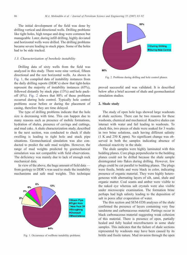
Fig. 2. Problems during drilling and hole control phases.
86 M.A. Mohiuddin et al. / Journal of Petroleum Science and Engineering 55 (2007) 83–92
The initial development of the field was done bydrilling vertical and directional wells. Drilling problemslike tight holes, high torque and drag were common butmanageable. Later, during infill drilling, highly deviatedand horizontal wells were drilled. The drilling problemsbecame severe leading to stuck pipes. Some of the holeshad to be side tracked.
1.3. Characterization of borehole instability
Drilling data of sixty wells from the field wasanalyzed in this study. There were nine vertical, fifteendirectional and the rest horizontal wells. As shown inFig. 1, the compiled data of instability instances fromthe daily drilling reports (DDR's) show that tight-holesrepresent the majority of instability instances (65%),followed distantly by stuck pipe (13%) and hole pack-off (8%). Fig. 2 shows that 80% of these problemsoccurred during hole control. Typically hole controlproblems occur before or during the placement ofcasing, therefore they are time delayed.
The type of drilling problems indicate that the holesize is decreasing with time. This can happen due tomany reasons such as presence of mobile formations,hydration of shales, presence of cavings and cuttings,and mud cake. A shale characterization study, describedin the next section, was conducted to check if shaleswelling is leading to tight hole and stuck pipesituations. Geomechanical simulation was also con-ducted to predict the safe mud weights. However, therange of mud weights predicted by goemechanicalsimulation was not compatible with field observations.The deficiency was mainly due to lack of enough rockmechanical data.
In view of the above, the huge amount of field data—from geology to DDR's was used to study the instabilitymechanisms and safe mud weights. This technique
Fig. 1. Occurrence of wellbore instability problems.
proved successful and was validated. It is describedbelow after a brief account of shale and geomechanicalsimulation studies.
2. Shale study
The study of open hole logs showed large washoutsat shale sections. There can be two reasons for thesewashouts, chemical and mechanical. Reactive shales caninteract with water and fail leading to washouts. Tocheck this, two pieces of shale were soaked for 3 weeksin two brine solutions, each having different salinity(1 K and 250 K ppm). No significant change was ob-served in both the samples indicating absence ofchemical reactivity in the shale.
The shale samples were highly laminated with thinbedding planes. Core plugs perpendicular to the beddingplanes could not be drilled because the shale sampledisintegrated into flakes during drilling. However, fewplugs could be cut parallel to bedding planes. The plugswere fissile, brittle and were black in color, indicatingpresence of organic material. They were highly hetero-geneous with alternating layers of silt, sand, shale andorganic matter. Coal seams and amber were visible tothe naked eye whereas salt crystals were also visibleunder microscopic examination. The formation brineperhaps had high salinity leading to the deposition ofsalt in pores after evaporation of water.
The thin section and SEM-EDS analyses of the shaleconfirmed the presence of layers containing very finesandstone and carbonaceous material. Partings occur inblack carbonaceous material suggesting weak cohesionof this material. There is presence of open, partiallyhealed and fully healed microfractures in some shalesamples. This indicates that the failure of shale sectionsrepresented by washouts may have been caused by itsbrittle and fissile nature. Mud invasion through the open
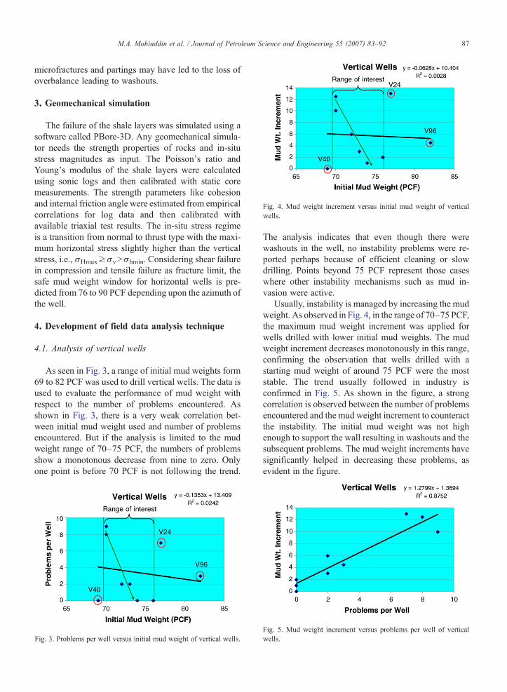
Fig. 4. Mud weight increment versus initial mud weight of verticalwells.
87M.A. Mohiuddin et al. / Journal of Petroleum Science and Engineering 55 (2007) 83–92
microfractures and partings may have led to the loss ofoverbalance leading to washouts.
3. Geomechanical simulation
The failure of the shale layers was simulated using asoftware called PBore-3D. Any geomechanical simula-tor needs the strength properties of rocks and in-situstress magnitudes as input. The Poisson's ratio andYoung's modulus of the shale layers were calculatedusing sonic logs and then calibrated with static coremeasurements. The strength parameters like cohesionand internal friction angle were estimated from empiricalcorrelations for log data and then calibrated withavailable triaxial test results. The in-situ stress regimeis a transition from normal to thrust type with the maxi-mum horizontal stress slightly higher than the verticalstress, i.e., σHmax≥σvNσhmin. Considering shear failurein compression and tensile failure as fracture limit, thesafe mud weight window for horizontal wells is pre-dicted from 76 to 90 PCF depending upon the azimuth ofthe well.
4. Development of field data analysis technique
4.1. Analysis of vertical wells
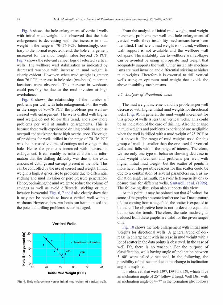
As seen in Fig. 3, a range of initial mud weights form69 to 82 PCF was used to drill vertical wells. The data isused to evaluate the performance of mud weight withrespect to the number of problems encountered. Asshown in Fig. 3, there is a very weak correlation bet-ween initial mud weight used and number of problemsencountered. But if the analysis is limited to the mudweight range of 70–75 PCF, the numbers of problemsshow a monotonous decrease from nine to zero. Onlyone point is before 70 PCF is not following the trend.
Fig. 3. Problems per well versus initial mud weight of vertical wells.
The analysis indicates that even though there werewashouts in the well, no instability problems were re-ported perhaps because of efficient cleaning or slowdrilling. Points beyond 75 PCF represent those caseswhere other instability mechanisms such as mud in-vasion were active.
Usually, instability is managed by increasing the mudweight. As observed in Fig. 4, in the range of 70–75 PCF,the maximum mud weight increment was applied forwells drilled with lower initial mud weights. The mudweight increment decreases monotonously in this range,confirming the observation that wells drilled with astarting mud weight of around 75 PCF were the moststable. The trend usually followed in industry isconfirmed in Fig. 5. As shown in the figure, a strongcorrelation is observed between the number of problemsencountered and the mud weight increment to counteractthe instability. The initial mud weight was not highenough to support the wall resulting in washouts and thesubsequent problems. The mud weight increments havesignificantly helped in decreasing these problems, asevident in the figure.
Fig. 5. Mud weight increment versus problems per well of verticalwells.
88 M.A. Mohiuddin et al. / Journal of Petroleum Science and Engineering 55 (2007) 83–92
Fig. 6 shows the hole enlargement of vertical wellswith initial mud weight. It is observed that the holeenlargement is decreasing with the increase in mudweight in the range of 70–76 PCF. Interestingly, con-trary to the normal expected trend, the hole enlargementincreased for the mud weight value beyond 76 PCF.Fig. 7 shows the relevant caliper logs of selected verticalwells. The wellbore wall stabilization as indicated bydecreased washout with increase in mud weight isclearly evident. However, when mud weight is greaterthan 76 PCF, increase in hole size (washouts) at certainlocations were observed. This increase in washoutscould possibly be due to the mud invasion at highoverbalance.
Fig. 8 shows the relationship of the number ofproblems per well with hole enlargement. For the wellsin the range of 70–76 PCF, the problems per well in-creased with enlargement. The wells drilled with highermud weight do not follow this trend, and show moreproblems per well at smaller enlargements. This isbecause these wells experienced drilling problems such asoverpull and stuckpipe due to high overbalance. The originof problems for wells drilled in the range of 70–76 PCFwas the increased volume of cuttings and cavings in thehole. Hence the problems increased with increase inenlargement. It can readily be inferred from this infor-mation that the drilling difficulty was due to the extraamount of cuttings and cavings present in the hole. Thiscan be controlled by the use of correct mud weight. If mudweight is high, it gives rise to problems due to differentialsticking and mud invasion or pore pressure penetration.Hence, optimizing themudweight to reduce the volume ofcavings as well as avoid differential sticking or mudinvasion is essential. Figs. 6, 7 and 8 also clearly show thatit may not be possible to have a vertical well withoutwashouts. However, these washouts can beminimized andthe potential drilling problems better managed.
Fig. 6. Hole enlargement versus initial mud weight of vertical wells.
From the analysis of initial mud weight, mud weightincrement, problems per well and hole enlargement ofvertical wells, three instability mechanisms have beenidentified. If sufficient mud weight is not used, wellborewall support is not available and the wellbore wallcollapses. The instability due to wellbore wall collapsecan be avoided by using appropriate mud weight thatadequately supports the wall. Other instability mechan-isms are mud invasion and differential sticking at highermud weights. Therefore it is essential to drill verticalwells using an optimum mud weight that avoids theabove instability mechanisms.
4.2. Analysis of directional wells
The mud weight increment and the problems per welldecreased with higher initial mud weights for directionalwells (Fig. 9). In general, the mud weight increment forthis group of wells is less than vertical wells. This couldbe an indication of the ease of drilling. Also the changein mud weights and problems experienced are negligiblewhen the well is drilled with a mud weight of 75 PCF orjust above it. The range of mud weights used for thisgroup of wells is smaller than the one used for verticalwells and falls within the range of interest. Therefore,we see only one type of behavior showing decrease inmud weight increment and problems per well withhigher initial mud weight, but the scatter of points ismore here. The possible reasons for this scatter could bedue to a combination of several parameters such as in-clination angle, azimuth, reservoir heterogeneity or ex-posure time for different wells, Santarelli et al. (1996).The following discussion also supports this view.
At this point, it may be pointed out that R2 values forsome of the graphs presented earlier are low.Due to natureof data coming from a huge field, the scatter is expected tobe there. The objective here is not to develop equationsbut to see the trends. Therefore, the safe mudweightsdeduced from these graphs are valid for the given rangesonly.
Fig. 10 shows the hole enlargement with initial mudweights for directional wells. A general trend of dec-rease in enlargement with increase in mud weight with alot of scatter in the data points is observed. In the case ofwell D9, there is no washout. For the purpose ofclassification, wells having angle of inclination between5–60° were called directional. In the following, thepossibility of this scatter due to the change in inclinationangle is explored.
It is observed that wells D97, D94 and D9, which havean inclination angle of 25° follow a trend. Well D61 withan inclination angle of 4–7° in the formation also follows
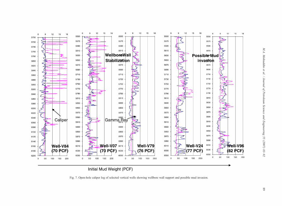
Fig. 7. Open-hole caliper log of selected vertical wells showing wellbore wall support and possible mud invasion.
89M.A.Mohiuddin
etal.
/Journal
ofPetroleum
Scienceand
Engineering
55(2007)
83–92
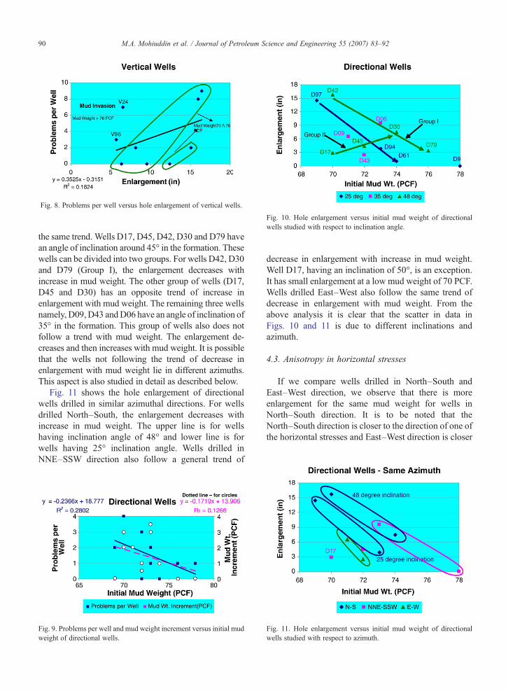
Fig. 8. Problems per well versus hole enlargement of vertical wells.
Fig. 10. Hole enlargement versus initial mud weight of directionalwells studied with respect to inclination angle.
90 M.A. Mohiuddin et al. / Journal of Petroleum Science and Engineering 55 (2007) 83–92
the same trend. Wells D17, D45, D42, D30 and D79 havean angle of inclination around 45° in the formation. Thesewells can be divided into two groups. For wells D42, D30and D79 (Group I), the enlargement decreases withincrease in mud weight. The other group of wells (D17,D45 and D30) has an opposite trend of increase inenlargement with mud weight. The remaining three wellsnamely, D09,D43 andD06 have an angle of inclination of35° in the formation. This group of wells also does notfollow a trend with mud weight. The enlargement de-creases and then increases with mud weight. It is possiblethat the wells not following the trend of decrease inenlargement with mud weight lie in different azimuths.This aspect is also studied in detail as described below.
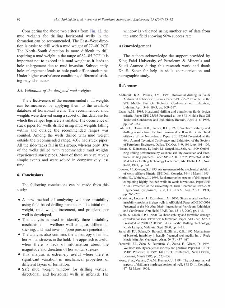
Fig. 11 shows the hole enlargement of directionalwells drilled in similar azimuthal directions. For wellsdrilled North–South, the enlargement decreases withincrease in mud weight. The upper line is for wellshaving inclination angle of 48° and lower line is forwells having 25° inclination angle. Wells drilled inNNE–SSW direction also follow a general trend of
Fig. 9. Problems per well and mud weight increment versus initial mudweight of directional wells.
decrease in enlargement with increase in mud weight.Well D17, having an inclination of 50°, is an exception.It has small enlargement at a low mud weight of 70 PCF.Wells drilled East–West also follow the same trend ofdecrease in enlargement with mud weight. From theabove analysis it is clear that the scatter in data inFigs. 10 and 11 is due to different inclinations andazimuth.
4.3. Anisotropy in horizontal stresses
If we compare wells drilled in North–South andEast–West direction, we observe that there is moreenlargement for the same mud weight for wells inNorth–South direction. It is to be noted that theNorth–South direction is closer to the direction of one ofthe horizontal stresses and East–West direction is closer
Fig. 11. Hole enlargement versus initial mud weight of directionalwells studied with respect to azimuth.
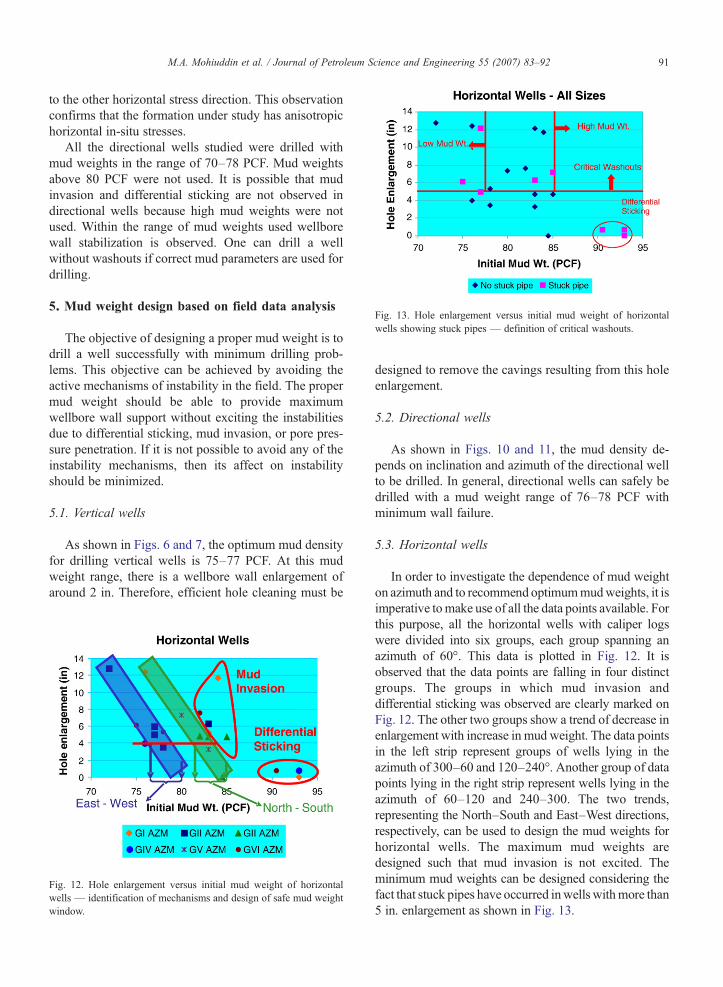
Fig. 13. Hole enlargement versus initial mud weight of horizontalwells showing stuck pipes — definition of critical washouts.
91M.A. Mohiuddin et al. / Journal of Petroleum Science and Engineering 55 (2007) 83–92
to the other horizontal stress direction. This observationconfirms that the formation under study has anisotropichorizontal in-situ stresses.
All the directional wells studied were drilled withmud weights in the range of 70–78 PCF. Mud weightsabove 80 PCF were not used. It is possible that mudinvasion and differential sticking are not observed indirectional wells because high mud weights were notused. Within the range of mud weights used wellborewall stabilization is observed. One can drill a wellwithout washouts if correct mud parameters are used fordrilling.
5. Mud weight design based on field data analysis
The objective of designing a proper mud weight is todrill a well successfully with minimum drilling prob-lems. This objective can be achieved by avoiding theactive mechanisms of instability in the field. The propermud weight should be able to provide maximumwellbore wall support without exciting the instabilitiesdue to differential sticking, mud invasion, or pore pres-sure penetration. If it is not possible to avoid any of theinstability mechanisms, then its affect on instabilityshould be minimized.
5.1. Vertical wells
As shown in Figs. 6 and 7, the optimum mud densityfor drilling vertical wells is 75–77 PCF. At this mudweight range, there is a wellbore wall enlargement ofaround 2 in. Therefore, efficient hole cleaning must be
Fig. 12. Hole enlargement versus initial mud weight of horizontalwells — identification of mechanisms and design of safe mud weightwindow.
designed to remove the cavings resulting from this holeenlargement.
5.2. Directional wells
As shown in Figs. 10 and 11, the mud density de-pends on inclination and azimuth of the directional wellto be drilled. In general, directional wells can safely bedrilled with a mud weight range of 76–78 PCF withminimum wall failure.
5.3. Horizontal wells
In order to investigate the dependence of mud weighton azimuth and to recommend optimummudweights, it isimperative tomake use of all the data points available. Forthis purpose, all the horizontal wells with caliper logswere divided into six groups, each group spanning anazimuth of 60°. This data is plotted in Fig. 12. It isobserved that the data points are falling in four distinctgroups. The groups in which mud invasion anddifferential sticking was observed are clearly marked onFig. 12. The other two groups show a trend of decrease inenlargement with increase in mud weight. The data pointsin the left strip represent groups of wells lying in theazimuth of 300–60 and 120–240°. Another group of datapoints lying in the right strip represent wells lying in theazimuth of 60–120 and 240–300. The two trends,representing the North–South and East–West directions,respectively, can be used to design the mud weights forhorizontal wells. The maximum mud weights aredesigned such that mud invasion is not excited. Theminimum mud weights can be designed considering thefact that stuck pipes have occurred inwells withmore than5 in. enlargement as shown in Fig. 13.
92 M.A. Mohiuddin et al. / Journal of Petroleum Science and Engineering 55 (2007) 83–92
Considering the above two criteria from Fig. 12, themud weights for drilling horizontal wells in theformation can be recommended. The East–West direc-tion is easier to drill with a mud weight of 77–80 PCF.The North–South direction is more difficult to drillrequiring a mud weight in the range of 82–85 PCF. It isimportant not to exceed this mud weight as it leads tohole enlargement due to mud invasion. Subsequently,hole enlargement leads to hole pack off or stuck pipe.Under higher overbalance conditions, differential stick-ing may also occur.
5.4. Validation of the designed mud weights
The effectiveness of the recommended mud weightscan be measured by applying them to the availabledatabase of horizontal wells. The recommended mudweights were derived using a subset of this database forwhich the caliper logs were available. The occurrence ofstuck pipes for wells drilled using mud weights fallingwithin and outside the recommended ranges wascounted. Among the wells drilled with mud weightoutside the recommended range, 40% had stuck pipes.All the side-tracks fall in this group, whereas only 10%of the wells drilled with recommended mud weightsexperienced stuck pipes. Most of these were relativelysimple events and were solved in comparatively lesstime.
6. Conclusions
The following conclusions can be made from thisstudy:
• A new method of analyzing wellbore instabilityusing field-based drilling parameters like initial mudweight, mud weight increment, and problems perwell is developed.
• The analysis is used to identify three instabilitymechanisms — wellbore wall collapse, differentialsticking, and mud invasion/pore pressure penetration.
• The analysis also confirms the anisotropy of in-situhorizontal stresses in the field. The approach is usefulwhen there is lack of information about themagnitude and direction of horizontal stresses.
• This analysis is extremely useful where there issignificant variation in mechanical properties ofdifferent layers of formation.
• Safe mud weight window for drilling vertical,directional, and horizontal wells is inferred. The
window is validated using another set of data fromthe same field showing 90% success rate.
Acknowledgement
The authors acknowledge the support provided byKing Fahd University of Petroleum & Minerals andSaudi Aramco during this research work and thankDr. S. Saner for help in shale characterization andpetrographic study.
References
Al-Buraik, K.A., Pasnak, J.M., 1993. Horizontal drilling in SaudiArabian oil fields: case histories. Paper SPE 25592 Presented at theSPE Middle East Oil Technical Conference and Exhibition,Bahrain, April 3–6, 1993, pp. 609–617.
Ezzat, A.M., 1993. Horizontal drilling and completion fluids designcriteria. Paper SPE 25595 Presented at the SPE Middle East OilTechnical Conference and Exhibition, Bahrain, April 3–6, 1993,pp. 645–654.
Fuh, G.F., Deom, D.B., Turner, R.D., 1991. Wellbore stability anddrilling results from the first horizontal well in the Kotter fieldoffshore of the Netherlands. Paper SPE 22544 Presented at the66th Annual Technical Conference and Exhibition of the Societyof Petroleum Engineers, Dallas, TX, Oct. 6–9, 1991, pp. 101–109.
Hassan, S., Klimentos, T., Badri, M., Sengul, M., Zeid, A., 1999. Optimi-zing drilling performance by wellbore stability evaluation and direc-tional drilling practices. Paper SPE/IADC 57575 Presented at theMiddle East Drilling Technology Conference, Abu Dhabi, UAE, Nov.8–10, 1999, pp. 1–11.
Lowrey, J.P., Ottesen, S., 1995. An assessment of themechanical stabilityof wells offshore Nigeria. SPE Drill. Complet. 34–41 March 1995.
Morita, N., Whitebay, L., 1994. Rockmechanics aspects of drilling andcompleting highly inclined wells in weak formations. Paper SPE27983 Presented at the University of Tulsa Centennial PetroleumEngineering Symposium, Tulsa, OK, U.S.A., Aug. 29–31, 1994,pp. 265–276.
Onaisi, A., Locane, J., Razimbaud, A., 2000. Stress related wellboreinstability problems in deepwells inABK field. PaperADIPEC-0936Presented at the 9th Abu Dhabi International Petroleum Exhibitionand Conference, Abu dhabi, UAE, Oct. 15–18, 2000, pp. 1–8.
Saidin, S., Smith, S.P.T., 2000. Wellbore stability and formation damageconsiderations for Bekok fieldK formation. Paper IADC/ SPE 62797Presented at 2000 IADC/SPE Asia Pacific Drilling Technology,Kuala Lumpur, Malaysia, Sept. 2000, pp. 1–11.
Santarelli, F.J., Dahen, D., BaroudI, H., Sliman, K.B., 1992.Mechanismsof borehole instability in heavily fractured rock media. Int. J. RockMech. Min. Sci. Geomech. Abstr. 29 (5), 457–467.
Santarelli, F.J., Zaho, S., Burrafato, G., Zausa, F., Giacca, D., 1996.Wellbore stability analysismade easy and practical. Paper IADC/SPE35105 Presented at 1996 IADC/SPE Conference, New Orleans,Lousiana, March 1996, pp. 523–532.
Wong, S.W., Veeken, C.A.M., Kenter, C.J., 1994. The rock mechanicalaspects of drilling a north sea horizontal well. SPE Drill. Complet.47–52 March 1994.


![SPE 146559 - A Unique Plug for a Restricted Wellbore[1] · PDF file2 SPE 146559 Fig 1—Directional survey illustrating the wellbore path. While pulling out of the hole following the](https://img.pdfslide.net/doc/110x75/5a8d9da87f8b9abb068ca691/spe-146559-a-unique-plug-for-a-restricted-wellbore1-spe-146559-fig-1directional.jpg)