Embed Size (px)
Citation preview
IJR International Journal of Railway
Vol. 2, No. 4 / December 2009, pp. 164-169
Vol. 2, No. 4 / December 2009 − 164 −
Analysis on Steering Capability of a New Bogie with Independently
Rotating Wheels
CHI Maoru†, ZENG Jing*, GUO Wenhao*, ZHANG Weihua* and JIN Xuesong*
Abstract
A new scheme about a coupled bogie with Independently Rotating Wheels was put forward firstly. And then it is fund by
theoretic analysis that the bogie takes on prominent radial capability on curved track and splendiferous restoring capa-
bility on tangent track. Lastly, a dynamic calculating model of the coupled bogie with independently rotating wheels has
been established and a dynamic simulation analysis on steering capability of the bogie was made and the simulation
results can inosculate foregoing theoretic analysis, which illuminates that the coupled bogie can solve drastically the dif-
ficulty about steering problem of independently rotating wheel.
Keywords : Independently rotating wheel, Coupled bogie, Steering capability
1. Introduction
As the independently rotating wheels(is shortly called as
IRW) can individually rotate around its axle while the axle
itself does not rotate, so its axle can be made into cranked
axle and thus the floor height of the vehicle can be low-
ered, therefore the IRW are generally adopted in low-floor
light rail vehicles. As known, IRW can’t generate longitu-
dinal creep forces that play a key role in the steering capa-
bility, so IRW has a poor steering capability. On the
tangent track, the IRW usually drift to one side of the track
and can’t restore to the center of the track, and on the
curved track, the IRW have larger attack angle, which usu-
ally causes the flange contact rail. Therefore, the IRW not
only cause serious wheel-rail wear but also increase the
risk of derailment.
The steering problem is a barrier for the development of
IRW, in order to solve this problem, a lot of solutions has
been put forward [1]. The initial solution is to design the
special wheel tread [2-3], which increase the contact angle
difference of left and right wheels, and the gravity restor-
ing force can be increased, which can make the wheelsets
restored, whereas this scheme can not let the IRW auto-
matically tend to the radical position on the curved track.
So some radical mechanisms have been put forward, for
instance, the Talgo train in Spain had successfully applied
forced steering mechanism for the single-axle bogie with
IRW [4]. However the forced steering mechanism applied
to the two-axle bogie with IRW does not work perfectly
[5], because the reasonable steering gain coefficient can’t
easily be obtained in the intricate condition of track. Japa-
nese developed a radical bogie that adjusts the wheelsets
to the radical position by centrifugal force[6]. But its effect
will be limited by the external condition such as curve
radius, superelevation and the running velocity. The Pro-
fessor Frederich in Germany has developed a bogie (Einel-
rad-Einelfahrwerk, is shortly called as EEF) [7-8], which
relay on the gravity to regulate the yaw angle of IRW. Yet
the bogie has too complicated structure and the cost of the
manufacture become higher.
Up to now, the application of IRW isn’t satisfying, so a
coupled bogie with IRW has been put forward in this
paper.
2. Steering Principle of the New Bogie
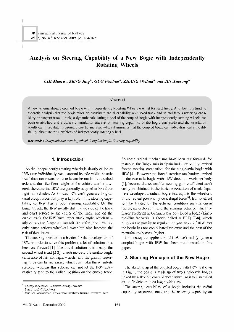
The sketch map of the coupled bogie with IRW is shown
in Fig. 1, the bogie is made up of two single-axle bogies
linked by a flexible coupled mechanism, so it is also called
as the flexible coupled bogie with IRW.
The steering capability of a bogie includes the radial
capability on curved track and the restoring capability on
†
*
Corresponding author : Southwest Jiaotong University
E-mail : [email protected]
State Key Laboratory of Traction Power, Southwest Jiaotong University, China
Vol. 2, No. 4 / December 2009 − 165 −
Analysis on Steering Capability of A New Bogie with Independently Rotating Wheels
tangent track. The radial capability is mainly embodied in
whether the attack angle can tend to zero on the curved
track and the restoring capability is embodied in whether
the lateral displacement of the wheelsets departuring the
centre of track can restore to zero on the tangent track.
In the lateral and yaw motion equations of coupled
bogie, the primary suspension stiffness of single-axle
bogie is far greater than its secondary suspension stiff-
ness, so in theoretical analysis, the frame and the
wheelsets can be considered as a whole and the motion
equations of bogie can be written as follows.
Lateral motion equation:
(1)
Yaw motion equation:
(2)
Where: i=1, 2, 3, 4; is MB the mass of the single-axle
bogie; IBZ is the yaw inertia of single-axle bogie; yBi is the
lateral displacement of single-axle bogie; is the yaw
angle of single-axle bogie; v is the vehicle running speed;
RBi is the radius of curved track; is the super-
elevation angle of the actual track; h is the distance
between mass center of bogie and rail surface; Twyi is the
lateral creep force of wheelset; Fgyi is the gravity restoring
force of wheelset; Fsyi is the lateral force of secondary
suspension; Mwzi is the yaw deflection torque produced by
the wheel-rail forces; Mszi is the yaw deflection torque pro-
duced by secondary suspension forces; Mczi is the yaw
deflection torque produced by flexible coupled mecha-
nism.
In this paper, the coupling mechanism in coupled bogie
only supply the stiffness of yaw angle for the leading and
trailing single-axle bogie and not interfere other motions,
so the role of coupling mechanism is only embodied in
yaw motion equation. When the coupling moment Mczi=0,
the coupled bogie evolved into two single-axle bogie with
IRW, and when the coupling moment Mczi is given a very
big value, the coupled bogie can approximately simulate
two-axle bogie with IRW, thus single-axle bogie and two-
axle bogie are only two extreme forms of the coupled
bogie.
2.1 The Analysis of Radial Capability on
Curve Track
According to the comparison of fig. 2, the radial capabil-
ity of the flexible coupled bogie with IRW can be intu-
itively understood.
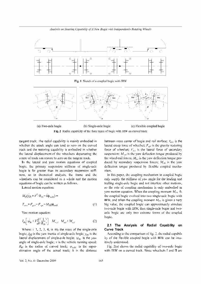
Fig. 2(a) shows the radial capability of two-axle bogie
with IRW on a curved track. Since wheelsets I and II are
MB y··Bi V
2RBi h
··φseBi+⁄+( ) =
Twyi Fgyi Fsyi MBgφseB+ + +
IBz ψBi
··V
d
dt----
1
RBi
-------⎝ ⎠⎛ ⎞+ Mwzi Mszi Mczi+ +=
ψBi
ϕseBi
Fig. 1 Sketch of a coupled bogie with IRW
Fig. 2 Radial capability of the three types of bogie with IRW on curved track
CHI Maoru, ZENG Jing, GUO Wenhao, ZHANG Weihua and JIN Xuesong
− 166 − IJR International Journal of Railway
constrained by the same frame, so the wheelset I has a
positive attack angle and wheelset II has a negative attack
angle, which indicates that the wheelsets I and II can not
outspread enough to achieve the radial position on the
curved track.
Fig. 2 (b) shows the radial capability of single-axle
bogie with IRW on a curve track. Since the wheelsets I
and II are not constrained by the same frame but by their
respective car bodies, so the wheelset I has a negative
attack angle and wheelset II has a positive attack angle,
which indicates that the Wheelsets outspread too much to
achieve the radial position on the curved track.
By further analysis, it is known that the reason why the
front and rear wheelsets of the two-axle bogie can not out-
spread enough to achieve the radial position on the curved
track is that the constrain on wheelsets applied by the rigid
frame is too great, while that of the two single-axle bogies
outspread too much to achieve the radial position on the
curved track is the absence of some necessary constrain
between the two wheelsets. However the flexible coupled
bogie can make up for the drawbacks of the former two
types of bogies. When a appropriate coupling stiffness for
the coupled bogie is chosen, the Wheelsets would advis-
ably outspread to achieve the perfect radial position on the
curved track(showed in Fig. 2(c)), which is just the inten-
tion of the flexible coupled bogie with IRW put forward in
this paper.
When a train steady-state running on curved track, the
left side of the equation (2) is equal to zero, while on the
right side of the equation, the yaw deflection torque Mwzi
which mainly generated by the longitudinal creep force is
very small and it can be ignored. So the equation (2) can
be written into:
(3)
(4)
(5)
Where: i= 1, 2; ksx denotes the one side secondary sus-
pension longitudinal stiffness; is the yaw angle stiff-
ness due to the coupled mechanism; bs is half of the
secondary suspension lateral span; bc is half of the cou-
pled mechanism lateral span; l is half of the nominal dis-
tance between front and back bogies centers; b is half of
the coupled bogie wheelbase; R is the radius of the circle
curve; is the yaw angle of bogie; is the yaw angle
of car body.
Considering the displacement of the wheelsets and the
deformation of the suspensions system are far shorter than
the length of the nominal distance between front and back
bogies centers 2l, thus the central part of the car body is
approximately tangential with the circle curve, i.e. .
When a train steady-state running on a circle curve track, in
order to let the front and rear wheelsets of the coupled
bogies achieve radial position completely, must have
. So according to equations (3) ~ (5), we can
obtain:
(6)
Reduces to
(7)
It is known from the equation (7) that the coupling stiff-
ness is only relational with the inherent configuration
parameters (such as l, b, bs, bc) of the train system and the
secondary suspension longitudinal stiffness ksx, yet irre-
spective to the external condition parameters(such as speed
of the train and curve radius of the track), which means
that as long as the coupling stiffness is selected accord-
ing to equation (7), whatever external condition(curve
radius and speed)change, the leading and trailing
wheelsets of the coupled bogie can run automatically to
radial position by the coordinated operation of the flexible
coupled mechanism and the secondary suspension sys-
tems of the vehicle. So the coupled bogie is also called as
the self-acting radial bogie with IRW.
2.2 The Analysis of Restoring Capability
on Tangent Track
When the train runs on tangent track, equation (1) will
be simplified as:
(8)
In equation (8), if the resultant force of right side has the
opposite direction to the lateral displacement yBi, the
wheelsets can restore. The direction of gravity restoring
force Fgyi is always opposite to the lateral displacement ybi.
The lateral creep force Twyi is related to the yaw angle of
wheelset and its phase is usually asynchrony to the lateral
displacement yBi. The lateral suspension force Fsyi related
to suspension stroke can’t be controlled artificially. So the
gravity restoring force and lateral creep force will usually
be changed to make the wheelset restored. There are three
measures as follows:
(1) Increasing the gravity restoring force Fgyi to make the
resultant force has the opposite direction to the lateral dis-
placement yBi. The measurement mainly relies on increas-
Mczi Mszi+ 0=
Mszi 2ksxbs
2ψBi ψc– 1–( )
i l
R---+–=
Mczi 1–( )ikψ
1–( )i 1+ψBi 1–( )
i 1+ψB i 1±( )–
2b
R------+=
Kψ
ψB ψc
ψc 0≈
ψBi =
ψB i 1+( ) 0=
kψ2b
R------ 2ksxbs
2 l
R---=
kψ
bs
2 l
b---ksx=
kψ
kψ
MBy··
Bi Twyi Fgyi Fsyi+ +=
Vol. 2, No. 4 / December 2009 − 167 −
Analysis on Steering Capability of A New Bogie with Independently Rotating Wheels
ing the contact angle difference of wheelsets and the tread
have to be designed specially.
(2) Reducing the lateral creep force Twyi to make the
resultant force has the opposite direction to the lateral dis-
placement yBi. This measurement mainly relies on adding
radial mechanism to make the yaw angle of wheelsets
approach to zero.
(3) Changing the direction of the lateral creep force Twyito make the lateral creep force Twyi has the opposite direc-
tion to the lateral displacement, which will make the
wheelset restore promptly. But the measurement can only
be achieved in some special bogie with special mecha-
nism.
Theoretically, the measurement (2) is the best of the
three because the radical measures can not only make the
wheelsets restore but also reduce the wheel-rail wear.
Actually this is the development tendency of IRW and the
new coupled bogie put forward in this paper also uses this
theory to make the IRW restore.
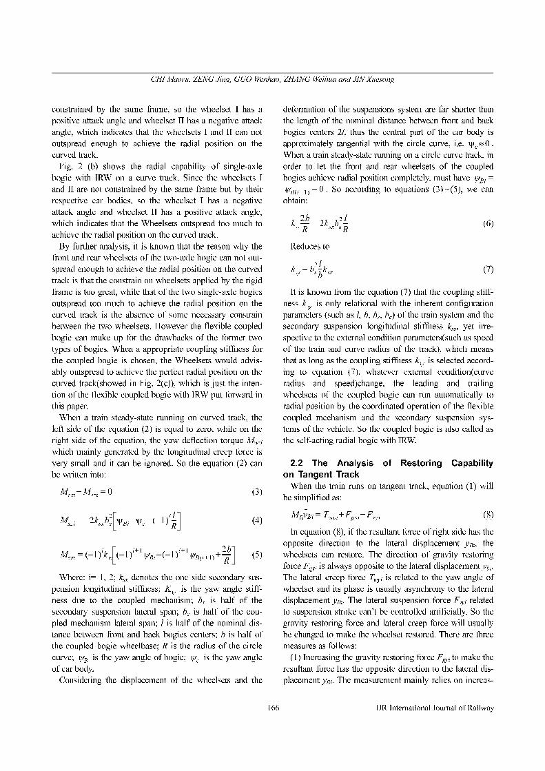
Fig. 3 shows restoring capability of three kinds of bogies
on tangent track. Fig. 3 (a) shows the restoring capability of
two-bogie with IRW on tangent track. When the wheelset I
runs to the right ride of the track, at the action of the gravity
restoring force, the wheelset I will have the tendency to
restore to the centre of the track, at the same time due to the
influence of the suspension system, the frame will generate
a positive yaw angle, which will make the wheelset I and II
also produce a positive yaw angle that will make wheelset I
and II produce positive lateral creep force. Because of the
influence of lateral creep force, wheelset I will be prevented
from restoring to restore to the centre of the track, thus
when the lateral creep force and the gravity restoring force
reach balance, wheelset I and II will stay at that position and
can not restore to the centre of the track.
Fig. 3 (b) shows the restoring capability of single-axle
bogie with IRW on tangent track. Since each wheelset has
its own frame, and there isn’t any connection between
wheelset I and II, they are only constrained by their own car
body. When wheelset I runs to the right side of the track, the
front car body will generates a negative yaw angle because
of the influence of suspend system. Since the front and rear
car bodies are jointed together, the rear car body will
generate a positive yaw angle. In this case, the front car
body will compel the wheelset I to generate a negative yaw
angle that will make wheelset I produce a negative
lateral creep force. The lateral creep force and the gravity
restoring force have the same direction, which will make the
wheelset I restore to the centre of the track. At last the
wheelset II will also restore to the centre of the track.
As for the coupled bogie with IRW, because of the coop-
eration action of suspend system and flexible coupling
mechanism, wheelset I and II can automatically adjust the
yaw angle near to zero which can decrease the lateral
creep force of wheelsets. In this case, the gravity restoring
force will play a key role in lateral wheel-rail force and it
will make the wheelsets quickly restore to the centre of the
track, just as Fig. 3(c).
3. The Design of Flexible Coupling Mechanism
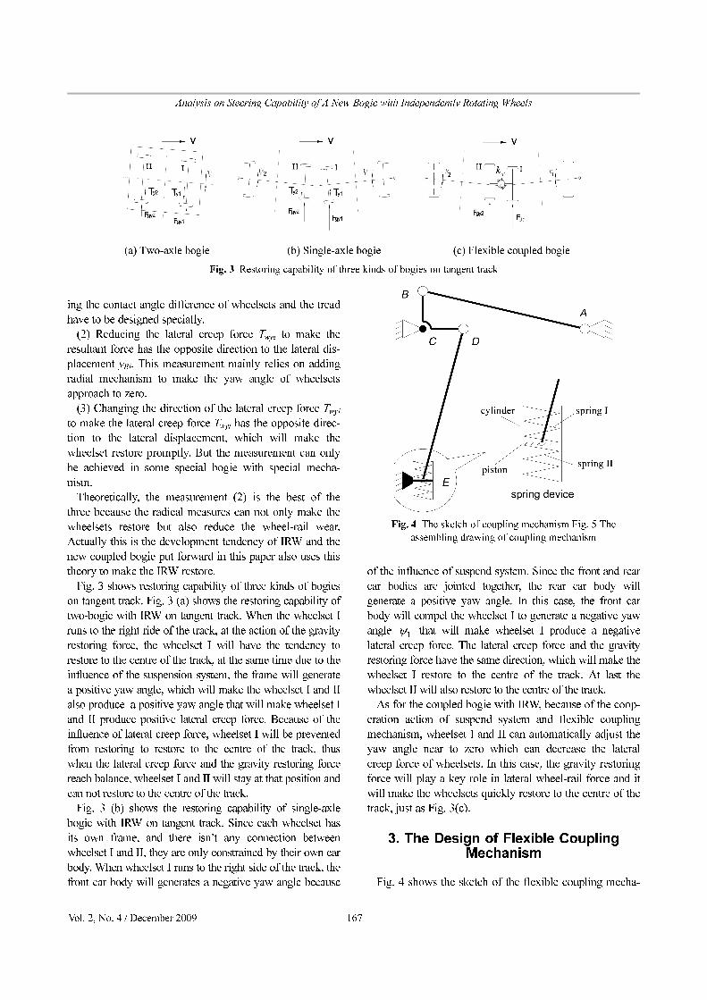
Fig. 4 shows the sketch of the flexible coupling mecha-
ψ1
Fig. 3 Restoring capability of three kinds of bogies on tangent track
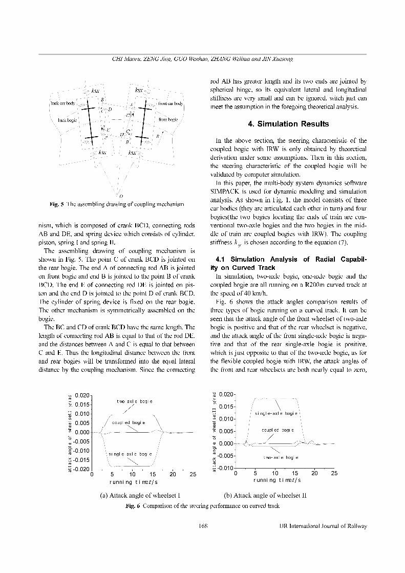
Fig. 4 The sketch of coupling mechanism Fig. 5 The
assembling drawing of coupling mechanism
CHI Maoru, ZENG Jing, GUO Wenhao, ZHANG Weihua and JIN Xuesong
− 168 − IJR International Journal of Railway
nism, which is composed of crank BCD, connecting rods
AB and DE, and spring device which consists of cylinder,
piston, spring I and spring II.
The assembling drawing of coupling mechanism is
shown in Fig. 5. The point C of crank BCD is jointed on
the rear bogie. The end A of connecting rod AB is jointed
on front bogie and end B is jointed to the point B of crank
BCD. The end E of connecting rod DE is jointed on pis-
ton and the end D is jointed to the point D of crank BCD.
The cylinder of spring device is fixed on the rear bogie.
The other mechanism is symmetrically assembled on the
bogie.
The BC and CD of crank BCD have the same length. The
length of connecting rod AB is equal to that of the rod DE,
and the distances between A and C is equal to that between
C and E. Thus the longitudinal distance between the front
and rear bogies will be transformed into the equal lateral
distance by the coupling mechanism. Since the connecting
rod AB has greater length and its two ends are jointed by
spherical hinge, so its equivalent lateral and longitudinal
stiffness are very small and can be ignored, witch just can
meet the assumption in the foregoing theoretical analysis.
4. Simulation Results
In the above section, the steering characteristic of the
coupled bogie with IRW is only obtained by theoretical
derivation under some assumptions. Then in this section,
the steering characteristic of the coupled bogie will be
validated by computer simulation.
In this paper, the multi-body system dynamics software
SIMPACK is used for dynamic modeling and simulation
analysis. As shown in Fig. 1, the model consists of three
car bodies (they are articulated each other in turn) and four
bogies(the two bogies locating the ends of train are con-
ventional two-axle bogies and the two bogies in the mid-
dle of train are coupled bogies with IRW). The coupling
stiffness is chosen according to the equation (7).
4.1 Simulation Analysis of Radial Capabil-
ity on Curved Track
In simulation, two-axle bogie, one-axle bogie and the
coupled bogie are all running on a R200m curved track at
the speed of 40 km/h.
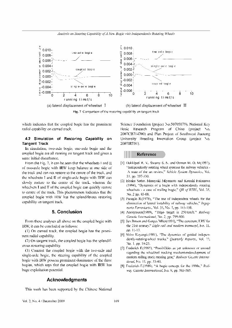
Fig. 6 shows the attack angles comparison results of
three types of bogie running on a curved track. It can be
seen that the attack angle of the front wheelset of two-axle
bogie is positive and that of the rear wheelset is negative,
and the attack angle of the front single-axle bogie is nega-
tive and that of the rear single-axle bogie is positive,
which is just opposite to that of the two-axle bogie, as for
the flexible coupled bogie with IRW, the attack angles of
the front and rear wheelsets are both nearly equal to zero,
kψ
Fig. 5 The assembling drawing of coupling mechanism
Fig. 6 Comparison of the steering performance on curved track
Vol. 2, No. 4 / December 2009 − 169 −
Analysis on Steering Capability of A New Bogie with Independently Rotating Wheels
which indicates that the coupled bogie has the prominent
radial capability on curved track.
4.2 Simulation of Restoring Capability on
Tangent Track
In simulation, two-axle bogie, one-axle bogie and the
coupled bogie are all running on tangent track and given a
same initial disturbance.
From the Fig. 7, it can be seen that the wheelsets I and II
of two-axle bogie with IRW keep balance at one side of
the track and can not restore to the centre of the track, and
the wheelsets I and II of single-axle bogie with IRW can
slowly restore to the centre of the track, whereas the
wheelsets I and II of the coupled bogie can quickly restore
to centre of the track. This phenomenon indicates that the
coupled bogie with IRW has the splendiferous restoring
capability on tangent track.
5. Conclusion
From these analyses all above on the coupled bogie with
IRW, it can be concluded as follows:
(1) On curved track, the coupled bogie has the promi-
nent radial capability.
(2) On tangent track, the coupled bogie has the splendif-
erous restoring capability.
(3) Contrast the coupled bogie with the two-axle and
single-axle bogie, the steering capability of the coupled
bogie with IRW possess prominent dominance of the three
bogies, which says that the coupled bogie with IRW has
huge exploitation potential.
Acknowledgments
This work has been supported by the Chinese National
Science Foundation (project No.50705079), National Key
Basic Research Program of China (project No.
2007CB714700) and Plan Project of Southwest Jiaotong
University Breeding Innovation Group (project No.
2007IRT01).
[1] Dukkipati R. V., Swamy S. N. and Osman M. O. M(1992),
“Independently rotating wheel systems for railway vehicles -
A state of the art review,” Vehicle System Dynamics, Vol.
21, pp. 297-330.
[2] Eisaku Satho, Masayuki Miyamoto and Katoshi Fukazawa
(1994), “Dynamics of a bogie with independently rotating
wheelsets - a case of trailing bogie,” QR of RTRI., Vol. 35,
No. 2 pp. 83-88.
[3] Panagin R.(1978), “The use of independent wheels for the
elimination of lateral instability of railway vehicles,” Ingeg-
neria Ferroviaria., Vol. 33, No. 2, pp. 143-150.
[4] Anonymous(1989), “Talgo target is 250 km/h,” Railway
Gazette International, No. 2, pp. 799-800.
[5] Jan Jhnson and Gorges Mller(1991), “The eurotram: LRV for
the 21st century,” Light rail and modern tramwayl, No. 11,
pp. 11-13.
[6] Shiro Koyangi.(1981), “The dynamics of guided indepen-
dently-rotating-wheel trucks,” Quarterly Reports., Vol. 22,
No. 1, pp. 19-25.
[7] Frederich F.(1985), “Possibilities as yet unknown or unused
regarding the wheel/rail tracking mechanismdevelopment of
modern rolling stock running gear,” Railway Gazette Interna-
tional, No. 11, pp. 33-40.
[8] Frederich F.(1988), “A bogie concept for the 1990s,” Rail-
way Gazette International, No. 9, pp. 583-585.
Fig. 7 Comparison of the restoring capability on tangent track