Embed Size (px)
Citation preview

ANALYSIS ON THIN SHEET METAL FEEDING CHARACTERISTIC BY A
SERVO ROLL FEEDER
MOHAMAD ZULHISYAM BIN MOHD RAZMI
This thesis is submitted as a partial fulfilment of the requirements for the award of the
degree of Bachelor of Mechanical Engineering
Faculty of Mechanical Engineering
UNIVERSITI MALAYSIA PAHANG
JUNE 2013

vii
ABSTRACT
This thesis was carried out to analyse thin sheet metal feeding characteristic
by a servo roll feeder. Although servo roll feeding has been seen to be very
successful in conventional sheet metal forming, no significant effort has been made
to enable the application of this technology to micro sheet metal forming. A metal
strip in micron size is very fragile, and it may be severely deformable if an
inappropriate feeding facility is deployed. A model of feeder was created and
simulation was further conducted to analyse the performance of servo roll feeder in
term of accuracy and repeatability during feeding process of thin sheet metal. Several
parameters were changed during simulation to acquire more data about servo roll
feeder performance. The analysed showed that many factors affect the feed process
in term of accuracy such as feed frequencies, feed distances and materials thickness.
viii
ABSTRAK
Tesis ini dijalankan untuk menganalisis ciri-ciri suapan kepingan logam nipis
oleh suapan gulungan bermotor. Walaupun suapan gulungan bermotor dilihat sangat
berjaya dalam lembaran pembentukan logam konvensional, tidak ada usaha ketara
telah dibuat untuk membolehkan penggunaan teknologi ini untuk pembentukan
logam bersaiz mikron. Kepingan logam dalam saiz mikron sangat rapuh, dan ia boleh
menjadi teruk jika perubahan suapan tidak bersesuian dilakukan. Satu model suapan
telah dicipta dan simulasi dijalankan untuk dianalisis prestasi suapan gulungan
bermotor dari segi ketepatan dan kebolehulangan semasa proses suapan pada
kepingan logam nipis. Beberapa aturan telah diubah dalam simulasi untuk
memperoleh lebih banyak data mengenai prestasi suapan gulungan bermotor.
Analisis menunjukkan bahawa banyak faktor mempengaruhi proses suapan dalam
ketepatan seperti kecepatan suapan, jarak suapan, dan ketebalan bahan.

ix
TABLE OF CONTENTS
TITLE PAGES
EXAMINER’S DECLERATION ii
SUPERVISOR’S DECLERATION iii
STUDENT’S DECLERATION iv
DEDICATION v
ACKNOWLEDGEMENT vi
ABSTRACT vii
ABSTRAK viii
TABLE OF CONTENTS ix
LIST OF TABLES xii
LIST OF FIGURES xiii
LIST OF ABBREVIATIONS xiv
LIST OF APPENDICES xv
CHAPTER 1 INTRODUCTION
1.1 Introduction 1
1.2 Project background 2
1.3 Problem statement 3
1.4 Objective of the project 3
1.5 Scope of studies 3
1.6 Overview of the thesis 4

x
CHAPTER 2 LITERATURE REVIEW
2.1 Introduction 5
2.2 Micro-Manufacturing 5
2.3 Micro-Parts 6
2.4 Micro-Forming 7
2.4.1 Definition 7
2.4.2 Micro-Forming Processes 7
2.4.3 Micro- Forming Machines 9
2.5 Sheet Metal Feeding 10
2.6 Types of Feeder For Micro-Forming 12
2.7 Servo Roll Feeder 15
2.8 Feeding Performance and Related Parameters 18
CHAPTER 3 METHODOLOGY
3.1 Introduction 20
3.2 Procedure 20
3.2.1 Modelling The Feeder 20
3.2.2 The Change of Parameter 22
3.2.3 Collecting The Data 22
3.3 Flow Chart 23
CHAPTER 4 RESULT AND DISCUSSION
4.1 Introduction 24
4.2 Result 24
4.2.1 effect of change feed distance 24
4.2.2 effect of change feed frequency 26
4.2.3 effect of change material thickness 28
4.2.4 effect of change material type 29
4.2.5 effect brake force 30
4.2.6 effect of motion profile 32

xi
4.3 Discussion 34
4.3.1 effect of change of feed distance and feed
frequency
34
4.3.2 effect of material thickness 34
4.3.3 effect of material types 35
4.3.4 effect of brake force 35
4.3.5 effect of motion profile 35
CHAPTER 5 CONCLUSION 36
5.1 Introduction 36
5.2 Conclusion 36
5.3 Recommendation 36
REFERENCES 37
APPENDIX A1 39
APPENDIX B1 40
APPENDIX B2 41
APPENDIX B3 42
APPENDIX B4 43
APPENDIX B5 44
APPENDIX B6 45

xii
LIST OF TABLES
TABLE NO. TITLE PAGE
2.1 Micro forming process 8

xiii
LIST OF FIGURES
FIGURE NO. TITLE PAGE
2.1 Parts scale and dimensions 6
2.2 Working principle of a roll feeder 10
2.3 Mechanical type feeder 13
2.4 Servo roll feeder 14
2.5 Pneumatic feeder 14
2.6 (a) Servo roll feeder by H&O Inc. 17
2.6 (b) Servo roll feeder by H&O Inc. 17
3.1 Model of feeder 21
3.2 Data and graph 22
3.3 Flow chart 23
4.1 Percentage vs accuracy of 1mm and 5mm feed
distance of carbon steel
25
4.2 Percentage vs accuracy of 1mm and 5mm feed
distance of stainless steel
26
4.3 Percentage vs accuracy of 1Hz and 3Hz feed
frequency carbon steel
27
4.4 Percentage vs accuracy of 1Hz and 3Hz feed
frequency stainless steel
27
4.5 Percentage vs accuracy of 50µm and 100µm carbon
steel thickness
28
4.6 Percentage vs accuracy of 50µm and 100µm
stainless steel thickness
29
4.7 Percentage vs accuracy of different materials types 30
4.8 Percentage vs accuracy of the effect brake force on
carbon steel
31
4.9 Percentage vs accuracy of the effect brake force on
stainless steel
31
4.10 Percentage vs accuracy of 45-45 motion profile 32
4.11 Percentage vs accuracy of 50-50 motion profile 33

xiv
LIST OF ABBREVIATIONS
FE Finite element
MEMS Micro-electromechanical systems
MST
PID
Micro-system technologies
Proportional Elongated Derivative
HSS High speed steel

xv
LIST OF APPENDICES
APPENDIX NO. TITLE PAGE
A1 Project Gantt chart 39
B1 Data feed distance 40
B2 Data feed frequency 41
B3 Data material thickness 42
B4 Data material types 43
B5 Data effect of brake force 44
B6 Data motion profile 45

CHAPTER 1
INTRODUCTION
1.1 INTRODUCTION
Forming is one of the most economic and mass process that contributes to
nearly 80% of everyday life objects production. Examples of products made of
forming process include, car, reinforced steel for constructions, wires, hand phones,
coins, etc. Forming process can be many, for example, coining, stamping, rolling,
extrusions, drawing etc. Stamping is one of the processes that can produce mass
production within short time and is seen economics. Stamping is a process of shaping
sheet metal to the designated end product.
In stamping process, sheet metal is fed into the machine (punch and dies) by a
transportation system called feeder. Feeders can be of mechanical type, pneumatic as
well as servo roll feeder. Servo roll feeder is seen as one of the flexible feeding
mechanisms due to feeding parameters can be changed easily. Feeding large and
thick sheet metal into a machine is no longer a problem since the technique used is
already matured. However, the challenge arises when very thin sheet (measured
around 50-100micron thick) is fed onto a forming/stamping machine. Sheet metals at
this thickness are very fragile and easily deformed if not handled appropriately.
In addition to that, parts produced by thin sheet metal usually in sub
millimeter size and some of it has micron range of part features. Conventional
feeding accuracy of 25micron is no longer good enough for this application. This is
because the achievable process accuracy is about the same size of the part features to
be produced from very thin sheet metals. Moreover, only few researches were

2
conducted to examine the feeding characteristics of thin sheet metal feeding. Lack of
know-how knowledge to understand feeding characteristics is the main issue in this
thin sheet metal forming. Therefore, this researches focuses on the thin sheet metal in
order to understand how it‟s behave during feeding process.
It is hoped that the know-how on the feeding characteristics of very thin sheet
metal is usable for micro-sheet-forming applications. Micro servo roll feeder (micro
version of conventional servo roll feeder) is used to study its performance when
feeding thin sheet metals. The analysis is conducted by ABAQUS where the model
of the feeder is created and analyzed. Then the very thin sheet behaviors or
characteristics during feeding are analyzed and discussed along with the feeder
performance in terms of its achievable positional accuracy and repeatability.
1.2 PROJECT BACKGROUND
The precision feeding for micro sheet forming cannot be achieved with
conventional, large scale sheet metal feeder. The miniaturization concept of micro
servo roll feeder still inherits the conventional inaccuracy. To achieve high
operational performance, several parameters were investigated, which led to more
feeding accuracy and repeatability of servo roll feeder. Therefore, FE simulations of
strip feeding were conducted to do analysis (Akhtar, 2010).
The sheet metal is metal in the form of a sheet that has the thickness between
foil and plate. The thickness of metal strip used in micro-sheet-forming are usually
less than 100 um. It is very fragile, and it may be severely deformed if an
inappropriate feeding facility is deployed. Therefore, FE simulations were conducted
to quantify a servo roll feeder performance with a view to determine and analyse the
feeding characteristic and strip behaviours.
There are several key factors in the characteristics of feeding were considered
for analysis. The change of feed frequencies, feed distances, brake force, motion
profiles, material thickness, and material types to the system was conducted to
analyse the performance of servo roll feeder in term of accuracy and repeatability.

3
1.3 PROBLEM STATEMENT
The modernization of this era expands the demands of micro-parts especially
in manufacturing industries. A lot of micro-forming machines have been designed to
fulfil the industries needed. Servo roll feeder is one of micro-forming machines that
serve in sheet metal feeding. These feeders perform well in speed and power required
for high speed and medium gauge material stamping applications. However, these
feeders usually are more vulnerable to the accuracy and repeatability problems which
may decrease it performance. Thus, improvements in feeding characteristics are
needed to increase the performance of servo roll feeder.
1.4 THE OBJECTIVES OF THE PROJECT
The objectives of the project are:
i. To conduct basic studies on micro-manufacturing.
ii. To analyse feeding characteristic in micro-forming application.
iii. To qualify servo roll feeder performance in terms of feeding accuracy
and repeatability.
1.5 SCOPE OF STUDIES
The scope of works involve in this study will be:
i. To study the characteristic of servo roll feeder.
ii. To perform the analysis on thin sheet metal feeding characteristic by a
servo roll feeder using FE simulation software, Abaqus.
iii. To investigates the best result in term of accuracy and repeatability
using the parameters.

4
1.6 OVERVIEWS OF THE THESIS
This report is divided into five chapters. Chapter one gives the brief content
and background of the project. The problem statement, objectives and scopes of the
studies are also discussed in this chapter.
In chapter two, the literature review of the study is discussed. This chapter
provides fundamental studies on the micro-manufacturing, micro-parts, and micro-
forming. Then, this literature reviewed about the types of the feeders existed in
micro-forming processes. Next, the literature reviewed about servo roll feeder.
Lastly, this literature reviewed about the feeding performance and related
parameters.
For chapter three, methodology of the analysis is discussed. Drawing model
of the feeder by ABAQUS is generated and the data collected was analysed in
Minitab software to create the histogram graph. The model then is tested and
analysed. After that, the procedure of feeding performance using related parameters
is discussed.
In chapter four, the result in form of histogram graph from simulation are
shown for further analysis. The result from difference values or type from several
parameters are shown and be discussed.
Lastly, in chapter five, the conclusions are to be made based on the objective
of this thesis.
CHAPTER 2
LITERATURE REVIEW
2.1 INTRODUCTION
The purpose of this chapter is to provide a review of past research efforts
related to thin sheet metal forming using servo roll feeder. This chapter start with the
brief introduction about micro forming. Next, a review about sheet metal feeding and
servo roll feeder was provided. Lastly, a review of relevant research studies about
feeding performance and related parameters was provided.
2.2 MICRO-MANUFACTURING
The definition of micro-manufacturing is the manufacturing of components or
devices on a micro scale. The term „micro-manufacturing‟ in the context of a
miniature factory is understood to be a micro-factory (Qin, 2006). However, the term
„micro-factory‟ is defined as a small manufacturing system conceived as a means of
achieving higher throughput with less space and reduced consumption of both
resources and energy via downsizing of production processes (Claessen, 2002).
Therefore, all the equipment has been reduced in the scale of the micro-machines to
reduce the energy consumptions, overhead costs, material requirements, reduce
pollutions and create a more user friendly production environment. As the result of
reducing of scales of equipment, the mass of the equipment could be reduced
dramatically and this will lead to the increasing of tool speed and production rates by
lowering down manufacturing cycle. The micro-forming machine was invented in
micro-manufacturing system to serve a production of micro-forming products.

6
2.3 MICRO-PARTS
A micro-part is defined as small parts with typical part-dimensions in the
range of sub-millimetres up to a few millimetres, although part-features may be in
the micro-meter range. The positional of micro-part is expected to be in the range of
0.1 to 10μm. Figure 2.1 illustrates the range of part and feature size machining
capability. Parts with machined features beyond 100μm are known as miniature
parts, whereas a maximum size of less than 5mm usually can be found in micro-
electromechanical systems (MEMS) applications.
Figure 2.1: Parts scales and dimensions
Source: Qin 2006

7
2.4 MICRO-FORMING
The application of micro-forming in industries nowadays has grown rapidly
since the demands of micro product increase. The examples of micro-forming
product exist such as cell phone cases, toys, and electronic components.
2.4.1 DEFINITION
The term „micro-forming‟ in the context of metal forming is the production of
parts or structures with at least two dimensions in the sub-millimetre range [Geiger,
2001). Parts of such size are commonly used more in extremely high numbers, in
particular for electronic components in micro-system technologies (MST) and micro-
electromechanical systems (MEMS) as they characterize today many products
pushing forward their miniaturization. The examples of part are fasteners, micro-
screws, sockets, and any kind of connecting element.
2.4.2 MICRO-FORMING PROCESSES
Nowadays, most of the micro-forming processes were tends to mimicking
conventional processes. These apply toward miniaturization and some has great
limitation in terms of its potential such as limited number of machining axes and
capability on roughing process only compare to well-developed macro-scale
processes.
Besides that, most of the micro-forming processes developed at present only
capable of machining soft materials. This is due to the usage of soft tooling such high
speed steel (HSS) as it was widely used in macro-processes. No harder materials can
be qualified under the usage of soft tooling. The only way out to avoid the usage of
micro-tools is by approaching and exploring non-contact machining process.
Noncontact machining is the only promising solution available for micro-process and
the potential is seen similar to the conventional manufacturing processes. The
examples of micro-forming process are subtractive, additive, deforming, joining, and
hybrid process. These micro-forming processes are shown in Table 2.1.

8
Table 2.1: Micro-forming Processes
Types of
processes
Types of machining
Subtractive
processes
Micro-Mechanical Cutting, Laser Beam Machining, Electro
Beam Machining, Photo-chemical machining, etc.
Additive
processes
Surface coating, Micro-casting, Micro-injection moulding,
Sintering, Photo-electro-forming, Chemical deposition,
Polymer deposition, etc.
Deforming
processes
Micro-forming , Hot-embossing, Micro/Nano imprinting, etc.
Joining
processes
Micro-Mechanical-Assembly, Laser-welding, Resistance,
Laser, Vacuum Soldering, Bonding, Gluing, etc.
Hybrid
processes
Micro-Laser-ECM, Micro-EDM and Laser assembly, Laser-
assisted micro-forming, Micro assembly injection moulding,
Combined micro-machining and casting, etc.
Source: Qin 2009

9
2.4.3 MICRO-FORMING MACHINES
The design of conventional, large-scale machines has been upgraded for
manufacture of micro-component with enhanced precision. These machines are of
much smaller size compared to the conventional, large-scale machines. The
enhanced precision may be achieve through the combination of design forming tools
to address concerning the size of small component and higher precision equipment.
These machines may be designed primarily to manufacture components with
precisions in the millimetre ranges. With specific engineering modifications
implemented on these machines they could also be used for micro-forming
applications. Machines of smaller size may be built with newly enhanced parts and
designs that are particularly for micro-forming applications. These machines may
also be of normal size but incorporated with new concepts dedicated to micro-
forming (Qin, 2006).
The development of such machines has attracted a lot of interest from
researchers during last 10 years. Various new concepts are being experimented upon
to design and fabricate prototypes of the micro-machines.
The example of micro-stamping machines that use widely is BSTA300 series
machines from BRUDERER. This machine has high precision automatic punching
press with a perfected mass counterbalancing system and adjustable strokes, a press
force of 300 kN, speeds of from 100 to 1400 spm (fixed stroke max. 2000 spm), with
some specific considerations on the thermal and mechanical influences on the
precision of the guides and the ram, and is ideal for mass production.
Other machines which could be used for micro-forming purposes include the
mabu VP precision press series (speeds of up to 600 spm, with a maximum force of
250–500 kN). These machines have a press body with pre-stressed tension rods to
minimise deflections, an eccentric shaft and a connecting rod fitted entirely with
roller bearings, and a pre-stressed ram slide guiding with no play. These machines
are environment friendly in that there is no open lubricating system, no oil, and no
recycling of oil, and the machine is practically maintenance-free (Qin, 2006).

10
2.5 SHEET METAL FEEDING
The sheet metal feeding is used widely in micro-forming processes. Most
industry use high speed feeding in their industries to produce lots of material or parts
daily to fulfil market needed. The high speed feeding refers to the usage of a press
driven feeding system. The feeding system is well synchronized and powered by the
press. Roll feeder driven by the press through mechanical transmission system are
always synchronized to the rotation of the press, Figure 2.2. Furthermore, the feeder
always begins its motion at some predetermined point in the press cycle and finishes
at another predetermined point, regardless of the press speed or dies engagement.
Besides that, feeding system also drive by self-powered or stand-alone unit. The
motion was response to a signal from the press.
Figure 2.2: Working principle of a roll feeder
Source: Qin 2009
The ability to synchronization of press-driven feeds allows high-speed
indexing on press-driven feeds, the feeding of „in-die‟ transfers, or for use with an
unloader and for other applications that require the feed motion to be well
synchronized with the press rotation in order to avoid collision and tool breakage.
Meanwhile, the feed motion for all dies cannot begin until it reaches a point in the
stroke when the lack of timing adjustment occurs. Besides that, pneumatic and servo-
11
powered feeds operate independently of the press and allowing adjustment to enable
feeding to begin as soon as the die opens.
The press-driven feeds exhibit a very smooth motion. The motion called an
„s-curve motion profile‟ is better „trapezoidal-movement curve‟ used by most other
feeds. This s-curve motion profile enables the variation of the acceleration rate
throughout the index, hence resulting in the elimination of sharp transitions or
changes in velocity, which can cause slippage with other feeds. Most self-powered
feeds start their motion from a stationary condition directly into a fixed rate of
acceleration which results in a sharp velocity changes or transition called a „jerk‟
point. These jerk points typically occur at the beginning, middle, and end of each
move in trapezoidal motion (Akhtar, 2008).
Press-driven feeds make gradual transitions in velocity, with high-
acceleration and-deceleration in the interim due to their s-curve-designed cam. This
in turn leads to the elimination of these jerk points, while retaining the ability to
make high-speed indexes that are within reasonably good positional precision.
There are several disadvantages to most press driven feeds. The difficulty
occur when lack of adjustment, feed length/distance limitations, lack of inching
capability, and the absence of a control interface. Most of the press-driven feeds
require gear sets, rollers, or mechanical linkages to be changed to be able to adjust
the feed length only. They are also subjected to limitation in their range of feed
length/distance adjustment due to their being directly coupled to the press rotation
and their lack of ability to jog the strip for threading (U. Engel, 2002). In addition,
due to lack of electrical controls, mechanical feeds such as press-driven feeds cannot
accept a set-up input from, or provide an output feedback to, press-control or
automation systems.
The advantages of servo-driven roll-feeds include minimal space requirement
due their compact size, low maintenance, and high feed frequency. However, servo
feeds have some benefits that press-driven units do not have. Servo feeds utilize a
microprocessor-based control that gives them an added capability. Features such as

12
flexibility in changes of feed length/distance, programmable move patterns, self-
diagnostics capability, positional auto correction, and the ability to communicate
with an automation system, set them apart from other types of feeds.
Besides that, servo-driven roll feeds are also different to press-driven units in
the way that they are available in a wide variety of roll-unit configurations,
straighteners and unwinder. Most servo feeds manufactured at the present time
utilize a trapezoidal move/motion profile with four distinct „jerk‟ points that could
result in slippage but some are also available with controls that enable the execution
of s-curve move profiles to reduce the „jerking‟ motion (Okazaki. 2004).
2.6 TYPES OF FEEDER FOR MICRO-FORMING
There are many type of feeder. The three well- known feeders are mechanical
type feeder, servo roll feeder, and pneumatic feeder that still serve the metal forming
industries at the present time. The mechanical type feeder use of mechanical system
is good for feeding strips on medium and high speed pressure. The feeder performs
in high speed in feed frequency but lack in flexibility in feed distance. The
mechanical type feeder also has tendency to mechanical transmission wear. Figure
2.3 show mechanical feeder.
13
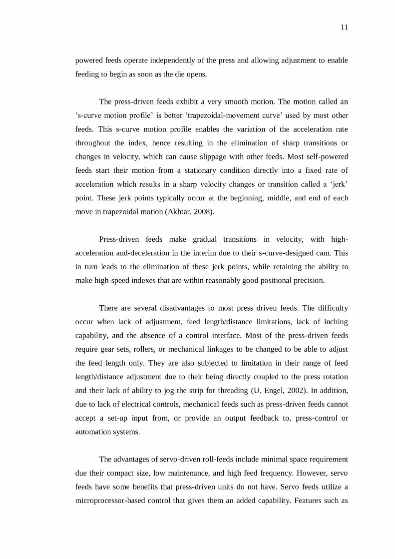
Figure 2.3: Mechanical feeder
The servo feeder uses electrical servomotor as shown in Figure 2.4. It is good
in flexibility in feed distance and also can perform in high speed feeding. Servo roll
feeder also better in accuracy and repeatability. Next, pneumatic feeder uses
pneumatic actuation as shown in Figure 2.5. Its performance in repeatability process
is very high. Pneumatic feeder also lack in accuracy when perform feeding process.

14
Figure 2.4: Servo roll feeder
Figure 2.5: Pneumatic feeder


![eprints.usm.myeprints.usm.my/34874/2/EKC217_SEM_I_1617.pdf · Bilangan minimum dulang teori pada refluks jumlah [2 markah] Lokasi optimum suapan danjumlah bilangan peringkat keseimbangan](https://img.pdfslide.net/doc/110x75/5ccafdfd88c993fa708c5102/-bilangan-minimum-dulang-teori-pada-refluks-jumlah-2-markah-lokasi-optimum.jpg)


![DESIGN, MODELING, AND PERFORMANCE COMPARISON …eprints.utm.my/id/eprint/5727/1/JTDIS47D[08].pdf · proximiti dan suapan bukaan. Kerja ini adalah usaha ... simulasi menggunakan cara](https://img.pdfslide.net/doc/110x75/5d19510f88c993495f8c786a/design-modeling-and-performance-comparison-08pdf-proximiti-dan-suapan-bukaan.jpg)