Embed Size (px)
Citation preview

492
DOI: 10.21205/deufmd. 2018205939
Analytical Dynamic Analysis of a Kinesthetic Haptic Device
Mehmet İsmet Can DEDE*1, Omar W. MAAROOF1, Marco CECCARELLI2
1İzmir Yüksek Teknoloji Enstitüsü, Mühendislik Fakültesi, Makina Mühendisliği Bölümü, 35430, İzmir
*1 (ORCID: http://orcid.org/0000-0001-6220-6678) 1 (ORCID: http://orcid.org/0000-0002-8910-2075)
2 University of Cassino, Laboratory of Robotics and Mechatronics, DIMSAT, 03043, Cassino (Fr.), Italy (ORCID: http://orcid.org/0000-0001-9388-4391)
(Alınış / Received: 11.08.2017, Kabul / Accepted: 08.12.2017,
Online Yayınlanma / Published Online: 15.05.2018) Keywords Haptics, Parallel Mechanisms, Dynamics
Abstract: A hybrid-structured kinesthetic haptic device based on an R-CUBE mechanism and a serial spherical wrist mechanism is considered in this article. This device is designed to simulate point-type contacts on the user. Hence, only three-dimensional forces are simulated to the user through the R-CUBE mechanism. This paper presents the quasi-static force analysis, gravity compensation calculations and dynamic analysis of the R-CUBE mechanism to serve for better understanding the capabilities of the mechanism and to be used in haptics controller development in the future studies. Making use of the derived dynamic equations, torque requirements from the actuators are examined for use in the haptic application scenarios.
Bir Kinestetik Haptik Cihazın Dinamik Analizi
Anahtar Kelimeler Haptik, Paralel Mekanizmalar, Dinamik
Özet: Bu makalede R-CUBE mekanizması ve seri küresel bilek mekanizmasını temel alan bir hibrit-yapılı kinestetik haptik cihaz üzerinde durulmuştur. Cihaz noktasal teması kullanıcıya hissettirmesi için tasarlanmıştır. Dolayısı ile, sadece üç-boyutlu kuvvetler kullanıcıya R-CUBE mekanizması üzerinden iletilmiştir. Bu makale, mekanizmanın kabiliyetinin daha iyi anlaşılması ve ilerideki çalışmalarda haptik denetleyicisinde kullanılması için, R-CUBE mekanizmasının yarı-statik kuvvet analizini, yerçekimi etkisi telafisi hesaplarını ve dinamik analizini sunmaktadır. Çıkarılan dinamik denklemler kullanılarak haptik uygulama senaryolarında gerekli eyleyici torkları incelenmiştir.
Dokuz Eylul University-Faculty of Engineering Journal of Science and Engineering
Volume 20, Issue 59, May, 2018
Dokuz Eylül Üniversitesi-Mühendislik Fakültesi Fen ve Mühendislik Dergisi Cilt 20, Sayı 59 , Mayıs, 2018

M.İ.C. Dede vd. / Analytical Dynamic Analysis of a Kinesthetic Haptic Device
493
1. Introduction Touch sensors in our bodies, the mechanoreceptors, can be classified into two groups based on the location in the body [1]. Kinesthetic receptors are located in muscles, tendons, and joints of the body and cutaneous receptors are located in the skin. Since the past two decades, haptics technology develops to stimulate both of these sensory systems [2]. Although there is strong evidence that cutaneous receptors contribute to kinesthetic perception, for the sake of simplicity, we adopt the definition in [2] and therefore, the haptic device presented in this paper is designed to stimulate kinesthetic receptors. The sense of touch that is accompanied by the visual and auditory feedback is enough to gather most of the information about a certain environment, which is generally called the slave environment. The addition of touch information increases the level of telepresence. If the interacted slave environment is a virtual environment, then this setting is called Virtual Reality (VR) application [3]. If the slave system is a real robotic device, then this type of setting is called teleoperation application. In both, physical interaction information from the virtual or real environment, such as forces, motions, textures, are sent back to the user through a haptic device. Currently, haptic devices find use in many VR and teleoperation applications such as computer-aided design, entertainment, education, training, rehabilitation, nano-manipulation, and virtual sculpting. Several types of haptic devices have been developed, and they have been employed in different types of tasks. However, especially for precise force reflection [4], large workspace needs [5] and precision required VR applications [6], high precision haptic systems are still required. In order to reflect back realistic touch information, besides the design on
the haptic device, the dynamic analysis should be carried out. Haptic devices do not always reflect back forces to simulate constraints but also they are driven dynamically to simulate for example the slip effect. Therefore, in this work, the dynamic analysis of the previously developed hybrid-structure haptic device is given in two parts as quasi-static force analysis and dynamic analysis. The aim of the quasi-static force analysis is to calculate joint torques to be applied while simulating constraints with various stiffness properties under the influence of gravitational forces acting on the mechanism. The aim of dynamic analysis is to calculate the required joint torques to simulate interaction forces such as slipping on an icy surface while applying forces on the surface. The hybrid-structure haptic device that is considered in this work is developed to simulate point type of contact, which means that it will only simulate forces that are reflected back from the slave environment in three-dimensional (3D) space but not the torque information. In order to accommodate this type of working scheme, the only active mechanism is the translational one, which is the R-CUBE mechanism. Therefore, dynamic analyses are carried out only for the R-CUBE mechanism. Section 2 provides information on classification of existing haptic devices and their designs. It is followed by the description of the designed hybrid-structure haptic device. Quasi-static force analysis and dynamic analysis of the device complete this paper. 2. Background In this section, the aim is to describe previous haptic applications and to clarify the concept of haptics by categorization. First, haptics technology is described with respect to their aimed receptors and mechanical structures.
M.İ.C. Dede vd. / Analytical Dynamic Analysis of a Kinesthetic Haptic Device
494
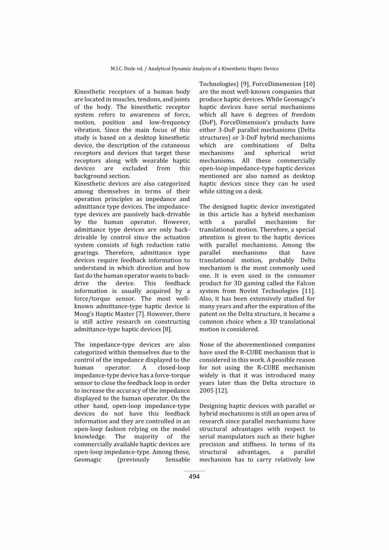
Kinesthetic receptors of a human body are located in muscles, tendons, and joints of the body. The kinesthetic receptor system refers to awareness of force, motion, position and low-frequency vibration. Since the main focus of this study is based on a desktop kinesthetic device, the description of the cutaneous receptors and devices that target these receptors along with wearable haptic devices are excluded from this background section. Kinesthetic devices are also categorized among themselves in terms of their operation principles as impedance and admittance type devices. The impedance-type devices are passively back-drivable by the human operator. However, admittance type devices are only back-drivable by control since the actuation system consists of high reduction ratio gearings. Therefore, admittance type devices require feedback information to understand in which direction and how fast do the human operator wants to back-drive the device. This feedback information is usually acquired by a force/torque sensor. The most well-known admittance-type haptic device is Moog’s Haptic Master [7]. However, there is still active research on constructing admittance-type haptic devices [8]. The impedance-type devices are also categorized within themselves due to the control of the impedance displayed to the human operator. A closed-loop impedance-type device has a force-torque sensor to close the feedback loop in order to increase the accuracy of the impedance displayed to the human operator. On the other hand, open-loop impedance-type devices do not have this feedback information and they are controlled in an open-loop fashion relying on the model knowledge. The majority of the commercially available haptic devices are open-loop impedance-type. Among these, Geomagic (previously Sensable
Technologies) [9], ForceDimenesion [10] are the most well-known companies that produce haptic devices. While Geomagic’s haptic devices have serial mechanisms which all have 6 degrees of freedom (DoF), ForceDimension’s products have either 3-DoF parallel mechanisms (Delta structures) or 3-DoF hybrid mechanisms which are combinations of Delta mechanisms and spherical wrist mechanisms. All these commercially open-loop impedance-type haptic devices mentioned are also named as desktop haptic devices since they can be used while sitting on a desk. The designed haptic device investigated in this article has a hybrid mechanism with a parallel mechanism for translational motion. Therefore, a special attention is given to the haptic devices with parallel mechanisms. Among the parallel mechanisms that have translational motion, probably Delta mechanism is the most commonly used one. It is even used in the consumer product for 3D gaming called the Falcon system from Novint Technologies [11]. Also, it has been extensively studied for many years and after the expiration of the patent on the Delta structure, it became a common choice when a 3D translational motion is considered. None of the abovementioned companies have used the R-CUBE mechanism that is considered in this work. A possible reason for not using the R-CUBE mechanism widely is that it was introduced many years later than the Delta structure in 2005 [12]. Designing haptic devices with parallel or hybrid mechanisms is still an open area of research since parallel mechanisms have structural advantages with respect to serial manipulators such as their higher precision and stiffness. In terms of its structural advantages, a parallel mechanism has to carry relatively low

M.İ.C. Dede vd. / Analytical Dynamic Analysis of a Kinesthetic Haptic Device
495
mass due to its ground-fixed actuators and this improves transparency of haptic devices. Therefore, parallel manipulators have higher loading capacity with respect to serial manipulators. Their major disadvantage is their limited workspace and low stiffness in singular positions. Today, still most of the published designs in the literature are based on Delta structure [13]. Nevertheless, there are other studies that make use of various types of parallel mechanisms to construct their haptic systems [14, 15]. 3. Description of the R-CUBE based hybrid-structure haptic device The haptic device, which is presented in this work, is a general purpose haptic device for fine VR and teleoperation applications. In order to develop a general purpose haptic device, the device type is selected as an open-loop impedance-type (passively back-drivable) kinesthetic desktop device since it can support a wide variety of desktop applications. Since hybrid mechanisms adopt the advantages of serial and parallel structures, the structure of the mechanism was selected to be configured as a hybrid structure. The hybrid structure is composed of a 3-DoF parallel mechanism for translational motions and a 3-DoF serial mechanism for rotational motion. The parallel mechanism was selected as a modified R-CUBE mechanism and it was designed to be actuated with direct driven motors to simulate point-type of contact, which means that only the forces along 3 axes are to be reflected back to the human with this mechanism. Additionally, angular position sensors are used in the fixed joints of the R-CUBE mechanisms to measure the wrist point position indirectly by using direct kinematics solutions. The mechanism for rotational motions is a passive mechanism with only position sensors to acquire the orientation of the handle. The superiority
of the R-CUBE mechanism with respect to any other 3-DoF translational mechanism with Cartesian structure is that it is composed of all revolute joints, which increases the workspace to footprint ratio. However, the R-CUBE structure has 9 more joint structures than the Cartesian parallel structure. As a result of having more joints and links, mechanical manufacturing and assembly may lead to significant problems and errors and more links and joints in the mechanical design can be sources of increased friction and flexion that will need proper considerations in motion and force control and will increase necessary actuating torques. The superiority of the R-CUBE structure with respect to the Delta structure is that the motion along each axis of its local frame is uncoupled (each actuator is responsible for the motion along one local orthogonal frame axis) and therefore, it has trivial kinematics and static force analysis which results in better controllability in a haptic use. However, relative to the Delta structure, the R-CUBE structure needs a large frame and occupies a large volume compared to its useful workspace. Also, with respect to the Delta structure, R-CUBE mechanism has not been extensively studied to be used in haptic devices. This paper serves to compensate for this shortcoming of the R-CUBE mechanism. Additionally, since haptic devices should not include singularity position within its workspace, by a careful design, R-CUBE mechanism does not have singularity positions inside its workspace. Design characteristics of the device are listed in [16] and a key feature is that it can produce three-dimensional 0.8 N of continuous force. For this device, the handle motion capturing system’s calibration was also presented in [17]. The original structure of R-CUBE [12] had some actuation problems due to the unequally distributed gravitational effects since the actuator operated for

M.İ.C. Dede vd. / Analytical Dynamic Analysis of a Kinesthetic Haptic Device
496
generating the motion along the z-axis by working the most against gravity. Hence, the original structure of R-CUBE is reoriented and the effect of gravity is distributed equally to all actuators since the orientation of the platform remains constant throughout the operation. The original R-CUBE design and the proposed design are shown in Fig. 1.a and Fig. 1.b respectively. They both have the 3(RRRR)RRR structure. Only one of the joint of the parallelogram (RRRR) on each leg is actuated and “ ” indicates the actuated joint. Since the link lengths of the parallelograms are the same, angular position sensor can be coupled to the passive fixed joint of the parallelogram.
(a) (b) Figure 1: R-CUBE designs: (a) Original design [14], (b) The re-oriented design
Although the scope of this article is the analytical formulation of the dynamics of the haptic interface, it should be noted that firstly, kinematics analysis has to be worked out. Although kinematics of the R-CUBE mechanism is sufficiently provided in [12], for the sake of having a common notation in the dynamic formulation, a brief review of the kinematics analysis of the haptic device is given in this section. Impedance-type kinesthetic haptic devices are expected to transmit motion demands (with respect to an acquired motion of the handle operated by the user) to the slave environment and reflect back the force/torque information to the user as received from the slave environment. To send a motion demand towards a virtual or real system by a haptic interface, the pose of the handle
should be measured. Since translational and rotational motions are decoupled in the proposed hybrid mechanism, the position of the wrist point 𝑾𝑟 where the serial-spherical wrist-based orientation mechanism’s rotation axes intersect is calculated for generating position information of the handle. The orientation of the handle is then calculated by acquiring the data from the position sensors that are directly attached to joints of the serial-spherical wrist mechanism. However, since the dynamic analysis is only carried out for the active translational mechanism, wrist mechanism’s full kinematics analysis is excluded from this article and the reader is encouraged to refer to [16] for the full kinematics analysis.
Figure 2: Mechanism parameters in the kinematic model
The location of the wrist point 𝑾𝑟 is also defined as the intersection point of the last link connection surfaces on the moving platform. The origin of the base coordinate frame O is selected to be at the intersection point of the unit vectors of the coordinate frame that are originated from the connection of actuated parallelogram links to the actuator axes. In Figure 2, the rotated frame is defined in terms of its origin and basis vectors as ℱ = {𝑂; 𝑼1, 𝑼2, 𝑼3} and the mechanism parameters are; 𝑆𝑖: the distance of the ith motor shaft along the 𝑼𝑖 direction from the rotated frame origin 𝑂 and 𝑙𝑖1: the length of the first link attached to the ith motor shaft. The parameters denoted in

M.İ.C. Dede vd. / Analytical Dynamic Analysis of a Kinesthetic Haptic Device
497
Figure 2 are used in the kinematics, quasi-static force, and dynamic analyses. The translational motion demand for the slave system is based on the calculation of the 𝑾𝑟 point position by using the real-time measurements from the position sensors. In other words, direct kinematics is used to calculate the motion demand. The calculation of the position vector of the tip point 𝑊𝑟 with respect to the origin point O in the rotated ground reference frame, which is denoted in Fig. 2, is
obtained as 𝑾𝑟 = ∑ 𝑊𝑟𝑖3𝑖=1 𝑼𝑖, where the
components of the 𝑾𝑟 vector are a function of the angular position of the actuator shafts 𝜃𝑖 that are given by 𝑊𝑟𝑖 =𝑆𝑖 + 𝑙𝑖1 sin 𝜃𝑖 ; 𝑖 = 1, 2, 3.
Figure 3: Parameters of R-CUBE’s first link
The location of the workspace can be changed by varying the 𝑆𝑖 parameters without affecting the size of the workspace. Therefore, this parameter can be tuned according to the user ergonomics. However, the size of the workspace is defined by the length of the first link li1 that appears in Figure 3. It should be noted that the zero position of the angle 𝜃𝑖 is represented by the straight red line in Figure 3. The total rotation limit of the first link is calculated by summation of the maximum amount of angular displacements allowed by mechanical limits on (+) direction and (-) direction of motion, 𝜃𝑖𝑇 = +𝜃𝑖 − (−𝜃𝑖). The workspace of the R-CUBE mechanism is a cube. The corners of the cubic workspace denoted with 𝑾𝑐𝑘 for 𝑘 𝜖 {1,2, … ,8} are calculated as shown in (1). Since there will be eight corners in a cube, there will be eight combinations of
± sign in (1) for the direction in three axes as given by
𝑾𝑐𝑘 = ∑ [𝑆𝑖 ± 𝑙𝑖1 sin (𝜃𝑖𝑇
2)] ∙
3
𝑖=1𝑼𝑖
𝑘 = 1,2 … 8
(1)
The link lengths with respect to the allowable total sweep of the first link angular motion are computed from (1) as
𝑙𝑖1 =𝑊𝑖
2∙sin(𝜃𝑖𝑇 2⁄ ); 𝑖 = 1, 2, 3, (2)
where 𝑊𝑖 indicates the length of the side of the cubic workspace in the 𝑼i direction. The workspace dimensions are selected as 120 x 120 x 120 mm in the rotated coordinate frame. The total motion range is equal in all directions, thus, the allowable total angle range of the first links is selected to be equal. When the first link length is selected by iteration as 65 mm, the total rotation limits of the first links were calculated to be 𝜃𝑖𝑇 = 134.76°, which covers 67.38° in clockwise and counter-clockwise directions from the null position. This selection was mainly to avoid singularities. Corner locations of the workspace are selected to provide better ergonomics in terms of convenient handling by the operator. A convenient handling position is a position where the operator’s hand does not come near to any of the links of the mechanism during the operation. This is achieved by modifying the shape of the links that are attached to the mobile platform and by setting the workspace location away from the origin. The workspace location is selected for better ergonomics by tuning S1, S2 and S3 to be 233 mm. In impedance-type kinesthetic haptic device controllers, mechanical impedance, which is described as the relation between the forces and velocities, is to be altered to reflect back the force information to the user. The velocity

M.İ.C. Dede vd. / Analytical Dynamic Analysis of a Kinesthetic Haptic Device
498
mapping required for such a calculation can be trivially accommodated by taking the time derivations of the position equations in the form
�̇�𝑟𝑖 = �̇�𝑖 ∙ 𝑙𝑖1 cos 𝜃𝑖 ; 𝑖 = 1, 2, 3. (3)
Inverse kinematics solution is necessary for dynamic analysis and controlling the haptic device to track motion demand for the handle action, i.e. during a simulating slipping condition. The inverse kinematics solutions of R-CUBE at position and velocity levels are given by
𝜃𝑖 = sin−1(
𝑊𝑟𝑖 − 𝑆𝑖
𝑙𝑖1)
�̇�𝑖 =𝑙𝑖1 cos 𝜃𝑖
�̇�𝑟𝑖
; 𝑖
= 1, 2, 3
(4)
Using the kinematics parameters determined for the re-oriented R-CUBE mechanism and by mounting a serial spherical wrist with potentiometers, the proposed device is manufactured and assembled as shown in Figure 4. The wrist is assembled on the moving platform produced from Delrin material in this figure. The mechanism is mounted on a base for ease of visualizing the actuators. The numbers in the red circles in Figure 4 indicate the actuator numbers used in the equations in this paper.
Figure 4: Manufactured and assembled device prototype
This prototype is actuated with three brushless DC (BLDC) motors. The motion of the mobile platform is calculated by using the acquired signals from the digital encoders located on the grounded joints and direct kinematics. Data exchange between the device’s motor drivers and the angular position sensors, and the control computer is achieved through a DAQ card, Quanser Q8. The orientation of the device can be changed by mounting the device on a base shown in black color in Figure 4. 4 Quasi-Static Force Analysis In a kinesthetic haptic device application, once the pose of the handle is calculated and the information is sent to the slave side, the forces and torques that are obtained from the slave side need to be reflected by the haptic device to the user. Acquiring or calculating forces/torques in the slave side is not in the scope of the work presented in this article. However, in order to display these forces and/or torques by the handle of a kinesthetic haptic device, a quasi-static force analysis should be carried out. This analysis relates the forces to be applied to the handle through the respective torques applied by the actuators. The hybrid mechanism is designed to display point-type of contact, thus, the actuators are placed only on the translational mechanism to reflect forces along the 3 axes at the wrist point. Thus, the quasi-static force analysis is worked out only for the R-CUBE mechanism. For a quasi-static force analysis, several methods are available. Among these, in this work, virtual work principle is used for this analysis. Since the motion along the base frame axes is decoupled, the virtual work formulation is formulated independently for each axis as
𝐹𝑖 ∙ 𝛿𝑊𝑟𝑖 = 𝑇𝑖 ∙ 𝛿𝜃𝑖; 𝑖 = 1, 2, 3 (5)

M.İ.C. Dede vd. / Analytical Dynamic Analysis of a Kinesthetic Haptic Device
499
where 𝐹𝑖 is the applied force magnitude by the device along the 𝑼𝑖 direction and 𝑇𝑖 is the torque magnitude of the ith actuator. Finitely small displacement of the wrist point 𝑊𝑟 along the unit vectors of the rotated frame can be calculated as
𝛿𝑊𝑟𝑖 = 𝑙𝑖1 ∙ cos 𝜃𝑖 ∙ 𝛿𝜃𝑖; 𝑖= 1, 2, 3
(6)
Substituting (6) in (5), actuator torques are obtained as functions of the forces at the wrist point as
𝑇𝑖 = 𝐹𝑖 ∙ 𝑙𝑖1 cos 𝜃𝑖 ; 𝑖 = 1, 2, 3 (7) Therefore, the required amount of torques to be applied by the actuators in order to display the demanded forces at the wrist point is calculated by (7).
Figure 5: Mechanism links that contribute to the calculation of GTM, mi4 and mi5 masses (in light gray)
In order to enhance the telepresence by increasing the level of transparency (in other terms enabling the user to feel only the reflected forces that are sent from the slave side), it is generally useful to eliminate gravitational effects acting on the mechanism [18]. The weights of the mechanism parts are precisely measured after the manufacturing processes. In order to facilitate the next set of analyses, total mass of the system is decomposed into smaller portions as the link masses of the parallelograms, the mass of the mobile platform GTM, and the masses of the two passive links on each leg (mi4 and mi5, where i=1, 2, 3) connecting the mobile
platform to the parallelograms. Mobile platform and two passive links on each leg are presented in Figure 5 (light gray). Since the gravity is in the downward direction, in this configuration, all the actuators contribute to carrying GTM, mi4 and mi5 masses equally. The components of the force vector 𝑭𝐺 required to be applied to carry the described masses can be identified as
𝐹𝐺𝑖
= (𝐺𝑇𝑀 + 𝑚𝑖4 + 𝑚𝑖5). 𝑔𝑖(𝑅)
𝑖 = 1,2,3
(8)
where 𝐹𝐺𝑖 represents the magnitudes of the forces applied by each actuator at the wrist point and 𝒈𝑅 represents the gravitational acceleration vector as observed in the rotated frame. The gravity vector is represented in a rotated frame by using the formulation;
𝒈(𝑅) = 𝐂(𝑅,𝑊)𝒈(𝑊)
= [𝐂(𝑊,𝑅)]
−1𝒈(𝑊)
(9)
In which, 𝒈(𝑊) = [0 0 −𝑔]𝑇 , 𝑔 = 9.81 m/s2, 𝛽 = 45°, and 𝛾 = 35.26°. In (9), 𝐂(𝑅,𝑊) is the transformation matrix that is defined from the 𝑊 frame orientation to the 𝑅 frame orientation [16]. However, there are still two legs with masses mi4 and mi5 to be compensated by the work of all three actuators. The remaining effect of these masses are calculated by
𝑾𝑖4 = 𝑚𝑖4 ∙ (𝒈(𝑅) − 𝑔𝑖(𝑅) ∙ 𝑼𝑖)
𝑾𝑖5 = 𝑚𝑖5 ∙ (𝒈(𝑅) − 𝑔𝑖(𝑅) ∙ 𝑼𝑖)
(10)
The gravitational effect of the parallelograms and remaining gravitational effects of the legs 𝑾𝑖4 and 𝑾𝑖5 are dependent on the angular positions of the actuators. Therefore, for

M.İ.C. Dede vd. / Analytical Dynamic Analysis of a Kinesthetic Haptic Device
500
each actuator, the gravitational effect of parallelograms and legs needs to be calculated separately. Once again, virtual work principle is used to find the torques required from the actuators, Tpi, to withstand gravitational effects of the links. The mass centers of the links of the legs are shown in Figure 6. The reaction forces on the parallelograms and platform applied by the gravitational forces of each leg’s links are required to be calculated. In order to accomplish this calculation, first, the inverse kinematics analysis for each leg is carried out to find the angles 𝛼𝑖1and 𝛼𝑖2, which are described in Figure 6. The kinematics calculations to determine these angles are for a simple serial planar RR manipulator and therefore, the inverse kinematics calculation steps are not given in this paper. The mass centers of the links with respect to rotated link frames are indicated with vectors 𝒍𝑚𝑖4 and 𝒍𝑚𝑖5. The effective link lengths are denoted with 𝑙𝑖4 and 𝑙𝑖5. In order to use the same representation for each leg, the axis of rotation of the actuator is denoted with
𝑼𝑎(0)
. The axis perpendicular to 𝑼𝑎(0)
and
𝑼𝑖 is denoted with 𝑼𝑛(0)
in Figure 6. The link frame vector representations are selected with respect to this notification
as 𝑼𝑎(1)
, 𝑼𝑛(1)
, 𝑼𝑎(2)
and 𝑼𝑛(2)
.
Figure 6: Mass center locations of the links of passive legs
The reaction forces are calculated by using Newton-Euler formulation and free-body diagrams of each link, as presented in Figure 6, in the quasi-static form. The calculation of the reaction force 𝐹𝑖3𝑎 is not provided in this paper since it does not contribute to the calculation of necessary actuator torques for quasi-static equilibrium. Torque balancing equations are derived for about point 𝑝𝑖3 and 𝑝𝑖4 as
∑ 𝑴𝑝𝑖3 = (𝒐𝒊𝒄𝒊𝟓 −
𝒐𝒊𝒑𝒊𝟑)(0)
× 𝒈(𝑅) ∙ 𝑚𝑖5 +
(𝒐𝒊𝒄𝒊𝟒 − 𝒐𝒊𝒑𝒊𝟑)(0)
× 𝒈(𝑅) ∙
𝑚𝑖4 + (𝒐𝒊𝒑𝒊𝟓 − 𝒐𝒊𝒑𝒊𝟑)(0)
×𝑭𝑖5 = 0
(11)
∑ 𝑴𝑝𝑖4 = (𝒐𝒊𝒄𝒊𝟓 − 𝒐𝒊𝒑𝒊𝟒)(0) ×
𝒈(𝑅) ∙ 𝑚𝑖5 + (𝒐𝒊𝒑𝒊𝟓 − 𝒐𝒊𝒑𝒊𝟒)(0) ×𝑭𝑖5 = 0
(12)
where 𝑐𝑖𝑗 and 𝑝𝑖𝑗 are the mass centers
and joint centers, respectively. In the subscript, i represent the leg that these

M.İ.C. Dede vd. / Analytical Dynamic Analysis of a Kinesthetic Haptic Device
501
centers belong to, and the subscript j indicate the link they belong to. From the torque vectors 𝑴𝑝𝑖3 and 𝑴𝑝𝑖4, the torque
about 𝑼𝑖 is extracted to derive two
equations as 𝑴𝑝𝑖3 ∙ 𝑼𝑖 = 𝑀𝑝𝑖3𝑖 = 0 and
𝑴𝑝𝑖4 ∙ 𝑼𝑖 = 𝑀𝑝𝑖4𝑖 = 0. The reaction force
vector 𝑭𝑖5 applied by the platform to the leg is decomposed into two components as 𝐹𝑖5𝑎 and 𝐹𝑖5𝑛 considering the torque t
taken about the 𝑼𝑖 vector in the 𝑼𝑎(0)
−
𝑼𝑛(0)
plane. After 𝐹𝑖5𝑎 and 𝐹𝑖5𝑛 are solved from (11) and (12), the reaction force at point 𝑝𝑖3 applied by parallelogram to the leg is calculated as
𝐹𝑖3𝑛 = (𝑚𝑖4 + 𝑚𝑖5) ∙ 𝑔𝑗(𝑅)
+
𝐹𝑖5𝑛 (13)
with the sequence when 𝑖 = 1, 2, 3 and 𝑗 = 3, 1, 2. Finally, these reaction forces on the legs that contribute to determining the necessary actuator torques to maintain quasi-static equilibrium are calculated as
𝑇𝑙1 = 𝑙11 cos 𝜃1 ∙ (𝐹35𝑎+ 𝐹25𝑛)+ 𝑙11 sin 𝜃1∙ 𝐹13𝑛
𝑇𝑙2 = 𝑙21 cos 𝜃2 ∙ (𝐹35𝑛+ 𝐹15𝑎)+ 𝑙21 sin 𝜃2∙ 𝐹23𝑛
𝑇𝑙3 = 𝑙31 cos 𝜃3 ∙ (𝐹25𝑎+ 𝐹15𝑛)+ 𝑙31 sin 𝜃3∙ 𝐹33𝑛
(14)
The mass centers of the parallelograms are shown in Figure 7, where moving link masses are denoted with mi1, mi2, and mi3.
Figure 7: Mass center locations of a
parallelogram’s links
Virtual work principle is used to determine the torques required to withstand the gravitational effects of the parallelogram links for each actuator. It should be noted that the coupler is a rigid body and parallelogram effective link lengths are equal to each other. Therefore, the motion of the coupler link is translational and it is equivalent to the linear motion of the joint of the first link that is attached to the coupler. Therefore, the distance from the actuator to calculate the motion of the coupler is taken as 𝑙𝑖1 which will be used in the next set of equations as 𝑙𝑚𝑖2 = 𝑙𝑖1. Infinitesimal amount of motion of the mass centers is represented by
𝛿𝑿𝑚𝑖k =𝜕 𝒐𝒊𝒍𝒎𝒊𝐤
𝜕𝜃𝑖. 𝛿𝜃𝑖 ; 𝑘 =
1, 2, 3
(15)
Virtual work equality by taking into account the gravitational forces of the parallelogram links can be expressed as
𝑇𝑝𝑖 . 𝛿𝜃𝑖 =
[𝒈(𝑅)]𝑇
(𝑚𝑖1 . 𝛿𝑿𝑚𝑖1 +𝑚𝑖2 . 𝛿𝑿𝑚𝑖2 + 𝑚𝑖3 . 𝛿𝑿𝑚𝑖3)
(16)
(16) is re-organized and generalized to calculate the required torques 𝑇𝑝𝑖 at each

M.İ.C. Dede vd. / Analytical Dynamic Analysis of a Kinesthetic Haptic Device
502
actuator to withstand the gravitational effects of the parallelogram links as
𝑇𝑝𝑖 = −𝑔𝑖(𝑅) ∙ (∑ 𝑚𝑖𝑗 ∙
3
𝑗=1
𝑙𝑚𝑖𝑗) ∙ (cos 𝜃𝑖 − sin 𝜃𝑖)
(17)
Finally, to calculate the total torque 𝑇𝑡𝑖 to display the required task forces at the wrist point and to eliminate the gravitational effects, (7), (8), (14) and (17) are used in formulating (18).
𝑇𝑡𝑖 = −[(𝐹𝑖 + 𝐹𝐺𝑖) ∙ 𝑙𝑖1 ∙ cos 𝜃𝑖] + 𝑇𝑝𝑖 + 𝑇𝑙𝑖
(18)
The material for the links was selected as 1060 Alloy Aluminum while the moving platform and the orientation mechanism were produced from Delrin material. Table 1 lists the physical properties of the links in terms of mass, inertia, the center of mass and effective link length. These are used to calculate the actuator torques to withstand gravitational effects when no other external force is applied.
An analysis is carried out to find the torque range of each motor within the workspace when a force of 0.8 N along each axis is to be applied under gravitational effects. For the worst case
scenario, the force along the 𝑼3(𝑊)
axis is
selected to be in the opposite direction of the gravity vector. The maximum torque requirement was found to be about 0.22 Nm near the middle of the workspace. The total computed torque from quasi-static force analysis is represented in Figure 8 for only actuator 1 with respect to end-effector location inside the workspace of the mechanism. The plots for the other two actuator torques have the same distribution as in Figure 8 but along their own axes of action. Therefore the torque distribution on each 𝑼2 − 𝑼3 plane along the 𝑼1 axis for actuator 1 is the same as the torque distribution on each 𝑼1 − 𝑼3 plane along the 𝑼2 axis for actuator 2 and on each 𝑼1 − 𝑼2 plane along the 𝑼3 axis for actuator 3.
Table 1: Physical parameters of the mechanism’s links in the prototype shown in Figure 4 Link1 Link2 Link3 Link4 Link5 Platform
Mass (gr.) 𝑚𝑖1
49.64 𝑚𝑖2 56
𝑚𝑖3 100.8
𝑚𝑖4 44.1
𝑚𝑖5 61.3
𝐺𝑇𝑀 140.5
Inertia (kg.mm2)
𝐼𝑐𝑖1 28.5
_ 𝐼𝑐𝑖3
37.3 𝐼𝑐𝑖4
45.3 𝐼𝑐𝑖5
165.96 _
Effective link length (mm)
𝑙𝑖1 65
𝑙𝑖2 76
𝑙𝑖3 65
𝑙𝑖4 93.15
𝑙𝑖5 155
_
Mass center of link (mm)
𝑙𝑚𝑖1 14.87
_ 𝑙𝑚𝑖3 7.4
𝑙𝑚𝑖4
= 43.13 �⃗⃗⃗�𝑎(1)
+ 7.71 �⃗⃗⃗�𝑛(1)
𝑙𝑚𝑖5
= 74.81 �⃗⃗⃗�𝑎(2)
− 11.36 �⃗⃗⃗�𝑛(2)
_

M.İ.C. Dede vd. / Analytical Dynamic Analysis of a Kinesthetic Haptic Device
503
Figure 8: Map of the actuator 1 torque with respect to the location of the end-effector (173 mm to 293mm with a 5mm resolution) It is observed from Figure 8 that the torques applied at various locations of the workspace for quasi-static equilibrium are not constant and even at certain configurations can be zero. This result indicates that the maximum applicable static force has a large variance due to the gravitational effects. One possible solution is to decrease the link weights and thus, decrease the band of the variance of the necessary torques from the actuators to apply the same amount of force at various locations of the workspace. Another solution is to implement passive gravity compensation by means of springs or counterweights or even both at the same time. 5. Dynamic Analysis In open-loop impedance-type kinesthetic devices, actuators are not only used to restrict the motion but they are also used for displaying motion and sometimes for increasing transparency of the device operation to compensate for frictional effects. The transparency can be improved in haptic devices by eliminating or minimizing inertial, frictional and gravitational effects. Although parallel configurations enable to locate the actuators on the device frame, they require more linkages and hence, more
link mass is carried by the actuators. However, by a proper design of links, the strength-to-weight ratio of these links can be improved and thus, the transparency of the device can be enhanced. However, the transparency and z-width calculations are not in the scope of this paper due to space limitations although it is in the scope of the development of this device. In this section, dynamic analysis is provided to simulate motion effects by control on the user of the haptic device. A dynamic analysis of the manipulator is worked out in two parts to obtain an analytical solution. The main reason for this is that the closed form solution for the differentiation of velocity equations cannot be derived straightforwardly. Therefore Lagrangian equations are not used for the whole analysis. In the first part, the dynamic effects are calculated for: First, the motion of the moving platform, second, the translational motion along the normal to the Euclidean planes of the legs that are connecting the moving platform to the parallelograms and third, the motion of the parallelogram links. The dynamic effects due to the motion of each leg’s links on their Euclidean planes are later calculated by Newton-Euler

M.İ.C. Dede vd. / Analytical Dynamic Analysis of a Kinesthetic Haptic Device
504
formulation. The Lagrangian formulation used for the first part is given by
𝑇𝑑𝑖1 =𝑑
𝑑𝑡(
𝜕𝐿
𝜕�̇�𝑖) − (
𝜕𝐿
𝜕𝑞𝑖) ; 𝑖 =
1,2,3 (19)
where 𝑇𝑑𝑖1 is a portion of the actuator torque that is required at the ith joint for the desired motion at the wrist point Wr. In the Lagrangian formulation, the potential energy term is neglected since the gravitational effects are already calculated in Section 4 and there is no elastic part in the system. Therefore, the Lagrangian term is composed of only the kinetic energy term 𝐾. Using the mass center location information, the velocity of the elements of the mechanism is derived and the total kinetic energy of the manipulator (excluding the motion of leg links in their Euclidean planes) is calculated as
𝐾 = 𝐾𝐺𝑇𝑀 + ∑ (𝐾𝑎𝑖 + 𝐾𝑖1 +3𝑖=1
𝐾𝑖2 + 𝐾𝑖3) (20)
where, 𝐾𝐺𝑇𝑀 is the kinetic energy of the moving platform and links that are connecting the moving platform to the parallelograms (only the translational motion of these along the normal of the links’ Euclidean plane); 𝐾𝑎𝑖 is the kinetic energy of the ith actuator with moment of inertia about its rotation axis 𝐼𝑎𝑖 = 164.65 kg·mm2, 𝐾𝑖1, 𝐾𝑖2 and 𝐾𝑖3 are the total kinetic energy of the i1th , i2th and i3th parallelogram links, respectively. The parts of kinetic energy equation defined in Eq. (20) are calculated as
𝐾𝐺𝑇𝑀 =1
2[𝐺𝑇𝑀 ∙ �̇�2 +
∑ (𝑚𝑖4 + 𝑚𝑖5) ∙ �̇�𝑖23
𝑖=1 ]
𝐾𝑎𝑖 =1
2𝐼𝑎𝑖�̇�𝑖
2
𝐾𝑖1 =1
2(𝐼𝑐𝑖1 + 𝑚𝑖1𝑙𝑚𝑖1
2 )�̇�𝑖2
(21)
𝐾𝑖2 =1
2𝑚𝑖3𝑙𝑖1
2 �̇�𝑖12
𝐾𝑖3 =1
2(𝐼𝑐𝑖3 + 𝑚𝑖3𝑙𝑚𝑖3
2 )�̇�𝑖2
where, �̇�𝑖 = �̇�𝑖𝑙𝑖1 cos 𝜃𝑖 𝑖 = 1, 2, 3 and �̇�2 = ∑ �̇�𝑖
23𝑖=1 .
Assuming that all three legs’ and parallelograms’ physical properties are identical, by substituting (21) and (20) in (19), the first portion of actuator torque to move the wrist point is calculated as
𝑇𝑑𝑖1 = (𝐺𝑇𝑀 + 𝑚𝑖4 + 𝑚𝑖5) ∙
(�̈�𝑖 cos2𝜃𝑖 − �̇�𝑖2
cos 𝜃𝑖 sin 𝜃𝑖) ∙
𝑙𝑖12 + 𝐼𝑎𝑖�̈�𝑖 + ( 𝐼𝑐𝑖1 +
𝑚𝑖1𝑙𝑚𝑖12
) �̈�𝑖 + 𝑚𝑖2𝑙𝑖12 �̈�𝑖 +
( 𝐼𝑐𝑖3 + 𝑚𝑖3𝑙𝑚𝑖32
) �̈�𝑖
(22)
The second part of the dynamics calculation is carried out for the motion of each leg’s links on their Euclidean planes. The procedure for the second part of the dynamic calculation is similar to the part presented in the quasi-static equilibrium calculations and first of all, the reaction forces at the link joints are calculated. However, in the dynamics calculations, the reaction forces are due to the motion of the links on their Euclidean planes and not due to their gravitational effects. Torques taken about point 𝑝𝑖3 and 𝑝𝑖4 are expressed as
∑ 𝑴𝑝𝑖3 = − (𝒐𝒊𝒄𝒊𝟓 −
𝒐𝒊𝒑𝒊𝟑)(0)
× �̈�𝑖5 ∙ 𝑚𝑖5 − 𝐼𝑐𝑖5 ∙( �̈�𝑖1 + �̈�𝑖2) − (𝒐𝒊𝒄𝒊𝟒 −
𝒐𝒊𝒑𝒊𝟑)(0)
× �̈�𝑖4 ∙ 𝑚𝑖4 − 𝐼𝑐𝑖4 ∙
�̈�𝑖1 + (𝒐𝒊𝒑𝒊𝟓 − 𝒐𝒊𝒑𝒊𝟑)(0)
×𝑭𝑑𝑖5 = 0
(23)
∑ 𝑴𝑝𝑖4 = − (𝒐𝒊𝒄𝒊𝟓 − 𝒐𝒊𝒑𝒊𝟒)(0) ×
�̈�𝑖5 ∙ 𝑚𝑖5 − 𝐼𝑐𝑖5 ∙ ( �̈�𝑖1 + �̈�𝑖2) +(𝒐𝒊𝒑𝒊𝟓 − 𝒐𝒊𝒑𝒊𝟒)(0) × 𝑭𝑑𝑖5 = 0
(24)

M.İ.C. Dede vd. / Analytical Dynamic Analysis of a Kinesthetic Haptic Device
505
Likewise, the case in the quasi-static equilibrium calculations, we get two equations for the torque components about 𝑼𝑖 . The reaction force vector 𝑭𝑑𝑖5 is decomposed into its two components as 𝐹𝑑𝑖5𝑎 and 𝐹𝑑𝑖5𝑛 and these components are calculated from the two equations that are derived from (23) and (24). Then the reaction force at point 𝑝𝑖3 applied by parallelogram to the leg is
𝐹𝑑𝑖3𝑛 = −𝑚𝑖4 ∙ �̈�𝑖4 ∙ 𝑼𝑗 − 𝑚𝑖5 ∙�̈�𝑖5 ∙ 𝑼𝑗 + 𝐹𝑑𝑖5𝑛
(25)
with the sequence when 𝑖 = 1, 2, 3, 𝑗 =3, 1, 2. It is sufficient to calculate three of the above-stated reaction forces because these forces affect the driving torques of the three actuators while the other components of these forces in the other directions have no effect on the actuators’ torques or have already been taken into account in first part using Lagrangian formulation. The required torques of the actuators (𝑇𝑑i2; 𝑖 = 1,2,3) to withstand the calculated reaction forces can be computed by using (14) and exchanging the reaction forces calculated for static effects by dynamic effects (i.e. using 𝐹𝑑35𝑎 instead of 𝐹35𝑎). Finally, the total amount of torque for compensating the gravitational effects, to display required amount of forces at the wrist point and to accomplish the motion designed for the wrist point can be calculated by using (18), (22) and (14) as
𝑇𝑖 = 𝑇𝑑𝑖1 + 𝑇𝑑𝑖2 + 𝑇𝑡𝑖 (26) In order to verify the dynamics calculations, a trajectory for the wrist
point is planned to follow a high-frequency sinusoidal motion at 7 Hz,
along 𝑼1(𝑤)
-direction with a total range of
4 cm. It was stated in [19] that human hand motion cannot go beyond the frequencies of 5–10 Hz. Therefore, generally, the bandwidth of a haptic interface is limited to 7 Hz. To perform this motion, the required torques at each driver is calculated using (26). The results for the required torques are displayed in Figure 9. Since the motion is defined in the world frame, the transferred motion to the rotated frame should result in a combined effort of all actuators, which can be observed from plots in Figure 9. The maximum torque requirement is just above 1 Nm for 7 Hz motion. Obviously, the torque requirement for the same type of motion carried out at different places of the workspace will be different. In order to verify the results, the mechanism’s solid model is transferred from SolidWorks into MATLAB Simulink in the block diagram modeling environment Simscape/SimMechanics. Actuators and sensors are included in the transferred model to accomplish the designed motion and measure the resulting torques at the actuators. The model is simulated at 1 kHz sampling rate and the difference between the computed torques at the actuated joints and the calculated torques with (26) is bounded by ± 8.6 x 10⁻⁶ Nm for a total range of about 2 Nm. Therefore, we can conclude that the results of our calculations are satisfactory.

M.İ.C. Dede vd. / Analytical Dynamic Analysis of a Kinesthetic Haptic Device
506
Figure 9: Computed actuator torques for the tested motion trajectory at 7 Hz
After the verification of the results, a series of simulations are run for a variety of dynamic motions. Three positions along each axis of the rotated frame, which are the boundaries at two ends and the midpoint of the workspace, are used specify 27 measurement points to define the worst-case scenarios. The motion is defined along the 𝑼1 axis of the rotated frame so that the majority of the work will be done by a single actuator (actuator 1) during the motion. The largest torque requirements are calculated when the mechanism is retracted to the lower end of the boundary which is the closest location of the end-effector to the world frame origin. The maximum torque requirement at 7 Hz for a total displacement of 4 cm along the 𝑼1 axis is calculated to be 3.43 Nm. When the total displacement is reduced to 2 cm, the maximum torque requirement is calculated to be 1.78 Nm. Although the dynamic range of a human hand is limited to 7 Hz, the device is tested for higher frequency motions at 14 Hz and 21 Hz for a displacement of 4 cm. The results of these tests are a maximum actuator torque of 13.32 Nm and 29.79 Nm, respectively. These results are used in selecting suitable actuation system.
6. Conclusions The design of the device considered in this work includes an R-CUBE mechanism for translational motion and serial spherical wrist mechanism for rotational motion. Since the only active mechanism in this haptic device is the R-CUBE mechanism and the passive wrist mechanism is treated as a payload, the necessary dynamic analysis is carried out for only the R-CUBE mechanism. The quasi-static force analysis is carried out to calculate the necessary actuator torques to reflect back the required amount of forces to a human operator. Gravitational effects are also compensated to relatively enhance the level of transparency. It should be noted that having variable torque requirements limits the range of forces to be applied at the wrist point in different locations of the workspace. A future work is planned for passive gravity balancing to expand this limitation. Kinesthetic haptic devices are also used to simulate dynamic effects of the environment such as slip effect on icy surfaces or surface roughness of an orange skin. In order to achieve such a task, dynamic analysis is required and in this paper, dynamic analysis is carried out by making use of both the Lagrange’s and the Newton-Euler methods. The required

M.İ.C. Dede vd. / Analytical Dynamic Analysis of a Kinesthetic Haptic Device
507
torques are calculated to display their variation for a relatively fast motion of the wrist point. The results indicated that for the R-CUBE mechanism, the actuator torques required for any desired motion can be calculated analytically with good precision for an ideal system in which the effects of joint frictions and clearances are neglected. In fast motion, actuator torques are calculated to be almost five times greater than the torques required for gravity compensation. Acknowledgments This research was supported by a Marie Curie International Reintegration Grant within the 7th European Community Framework Programme. We thank Dr. Erkin Gezgin for his help in Figure 2. References [1] Clark, F. J., Horch, K. W., Bach, S. M.,
Larson, G. F. 1979. Contribution of Cutaneous and Joint Receptors to Static Knee-Position Sense in Man, Journal of Neurophysiology, 42(3), 877-888.
[2] Hannford, B. and Okamura, A.M. 2008. Haptics. pp 719-735. Siciliano, B. and Khatib, O., ed. 2008. Springer Handbook of Robotics, Springer-Verlag, Germany, 1611p.
[3] Adams, R. J., Hannaford, B. 1999. Stable Haptic Interaction with Virtual Environments, IEEE Transactions on Robotics and Automation, 15, 465-473.
[4] Guo, Shuxiang, Mingyang Qin, Nan Xiao, Yuan Wang, Weili Peng, and Xianqiang Bao. "High precise haptic device for the robotic catheter navigation system." In Mechatronics and Automation (ICMA), 2016 IEEE International Conference on, pp. 2524-2529. IEEE, 2016.
[5] Parent, Q. U. E. N. T. I. N., and J. E. R. O. M. E. Perret. "Usability of a large-scale force-feedback device in different immersive environments." In EuroVR Conference. 2016.
[6] Guo, Shuxiang, Miao Yu, Yu Song, and Linshuai Zhang. "The virtual reality simulator-based catheter training system with haptic feedback." In Mechatronics and Automation (ICMA), 2017 IEEE International Conference on, pp. 922-926. IEEE, 2017.
[7] Van der Linde, Richard Q., Piet Lammertse, Erwin Frederiksen, and B. Ruiter. "The HapticMaster, a new high-performance haptic interface." In Proc. Eurohaptics, pp. 1-5. 2002.
[8] Arbuckle, Troy K., Manikantan Nambi, Jonathan E. Butner, William R. Provancher, and Jake J. Abbott. "Human velocity control of admittance-type robotic devices with scaled visual feedback of device motion." IEEE Transactions on Human-Machine Systems 46, no. 6 (2016): 859-868.
[9] 3D Systems Touch Haptic. https://www.3dsystems.com/haptics-devices/geomagic-touch (Accessed on 30.11.2017).
[10] ForceDimension. http://www.forcedimension.com/ (Accessed on 30.11.2017).
[11] Martin, S., Hillier, N. 2009. Characterisation of the Novint Falcon haptic device for application as a robot manipulator, Australasian Conference on Robotics and Automation, 2-4 December, Sidney, Australia, 291-292.
[12] Li, W., Gao, F., Zhang, J. 2005. R-CUBE, a Decoupled Parallel Manipulator only with Revolute Joints, Mechanism and Machine Theory, 40, 467-473.
[13] Ergin, M. A., Satıcı, A. C., Patoğlu, V. 2011. Design Optimization, Impedance Control and Characterization of a Modified Delta Robot, IEEE International Conference on Mechatronics, 13-15 April, İstanbul, 2011, 737-742.
[14] Abeywardena, Sajeeva, and Chao Chen. "Implementation and

M.İ.C. Dede vd. / Analytical Dynamic Analysis of a Kinesthetic Haptic Device
508
evaluation of a three-legged six-degrees-of-freedom parallel mechanism as an impedance-type haptic device." IEEE/ASME Transactions on Mechatronics (2017).
[15] Saafi, Houssem, Med Amine Laribi, and Said Zeghloul. "Redundantly actuated 3-RRR spherical parallel manipulator used as a haptic device: improving dexterity and eliminating singularity." Robotica 33, no. 5 (2015): 1113-1130.
[16] Bilgincan, T., Dede, M.İ.C. 2010. Development of an R-CUBE Based General Purpose Haptic Device System, ASME 2010 10th Biennial Conference on Engineering Systems Design and Analysis, 12-14 July İstanbul, 675-682.
[17] Dede, M.İ.C., Taner, B., Bilgincan, T. Ceccarelli M. 2014. Kinematic Analysis Validation and Calibration of a Haptic Interface, pp 375-381. M. Ceccarelli, V. Glazunov, ed. 2014. Advances on Theory and Practice of Robots and Manipulators Mechanisms and Machine Science, Volume 22, Springer, Dordrecht, Netherlands, 573p.
[18] Boztaş, S., Taner, B., Karabulut, M.G., Dede, M.İ.C. 2014. Haptik Cihazlarda Yer Çekimi Telafisinin Kullanıcı Performansı Üzerindeki Etkileri, Türkiye Otomatik Kontrol Komitesi Toplantısı, 11-13 Eylül, Kocaeli, 361-365.
[19] Tan, H.Z., Srinivasan, M.A., Eberman, B., Cheng, B. 1994. Human factors for the Design of Force-Reflecting Haptic Interfaces, Dynamic Systems and Control, 55(1), 353-359.