Embed Size (px)
Citation preview

274
Analytical Methods for Materials
Lesson 11Crystallography and Crystal Structures, Part 3
Suggested Reading• Chapter 6 in Waseda• Chapter 1 in F.D. Bloss, Crystallography and Crystal Chemistry: An Introduction, (Holt,
Rinehart and Winston, Inc., New York, 1971)

Point Groups
• Crystals possess symmetry in the arrangement of their external faces.
• Crystals also possess symmetry in the arrangement of lattice points and in the arrangement of objects placed on lattice points.
• When we put these two things together, we arrive at a new way to classify crystals in terms of symmetry.

Point Groups►Relate internal symmetry to external symmetry
of crystal.
• All symmetry elements intersect at a point. Symmetry operations are defined with respect to a point in space that does not move during the operation.
• There is no translational symmetry in a point group but there is always translational symmetry in a crystal.

277
Symmetry Operators• All motions that allow a pattern to be transformed from
an initial position to a final position such that the initial and final patterns are indistinguishable.
1. Translation
2. Reflection*
3. Rotation*
4. Inversion (center of symmetry)*
5. Roto-inversion (inversion axis)*
6. Roto-reflection*
7. Glide (translation + reflection)
8. Screw (rotation + translation)
Point groups:
symmetry operations defined with respect to a point in space that remains stationary
(i.e., does not move) during the operation.
Applies to objects occupying lattice
points.
2781. TRANSLATION
From Bloss, p. 141Inherent symmetry operation in crystals!

279
2. REFLECTION = m
From Bloss, p. 2
3. ROTATION
α = 360°/nn = fold of axis = 1,2,3,4 or 6
From Bloss, pp. 4, 5
4. INVERSION = i
From Bloss, p. 6

Fig. 6.9 Examples of symmetry operations. (a) Generation of a pattern by rotation of a motif through an angle of 180°. (b) Motifs as related by a mirror reflection. (c) Motifs related by inversion through a center. (d) Motifs related by 180° rotation an subsequent inversion; known as rotoinversion. From C. Klein and B. Dutrow, Manual of Mineral Science, 23rd Edition (John Wiley & Sons, 2007)

281
From Bloss, p. 7
Produce a change of hand
Produce replicas of same
hand

Fig. 6.12 Illustration of rotations that allow the motif to coincide with an identical unit for one-, two-, three-, four-, or six-fold rotation axes. The diagram for 2 represents a projection onto the xy plane of Fig. 6.9a. From C. Klein and B. Dutrow, Manual of Mineral Science, 23rd Edition (John Wiley & Sons, 2007)
α = 360°/nn = fold of axis = 1,2,3,4 or 6

Name of rotation Notation Angle SymbolDiad 2-fold 180°Triad 3-fold 120°Tetrad 4-fold 90°Hexad 6-fold 60°
Rotation – Symbols and NotationRotation – Symbols and Notation

Inversion
284
Inversion center = i
From Bloss, p. 6

Roto-Inversion
285α = 360°/n
n = fold of axis = 1,2,3,4 or 6
n From Bloss, p. 8
1 2
4 3 6
This one is the same is simple inversion (i)

Name of rotation Notation Angle SymbolDiad 2-fold 180°Triad 3-fold 120°Tetrad 4-fold 90°Hexad 6-fold 60°
Rotation – Symbols and NotationRotoinversion – Symbols and Notation

Fig. 6.14 (a) Illustration of an operation of rotoinversion, consisting of a 360° rotation and subsequent inversion through the center of the globe. (b) Projection of the two motif units (A and B) from the outer skin of the globe to the equatorial plane. (c) Location of the projected motifs on the equatorial plane. From C. Klein and B. Dutrow, Manual of Mineral Science, 23rd Edition (John Wiley & Sons, 2007)
Rotoinversion

Fig. 6.15 Illustration of operations of rotoinversion on motif units for all possible rotoinversion axes. From C. Klein and B. Dutrow, Manual of Mineral Science, 23rd Edition (John Wiley & Sons, 2007)
Rotoinversion

Combinations of Rotations
• Axes of rotation can only be combined in symmetrically consistent ways such that an infinite set of axes is not generated.
• All symmetry axes must intersect at a point that remains unchanged by the operations.
289
Fig. 6.18 The location of 4-, 3-, and 2-fold symmetry axes with respect to a cubic outline for 432. Note that the axes connect symbols on the opposite sides of the crystal and run through the center. Adapted from C. Klein and B. Dutrow, Manual of Mineral Science, 23rd Edition (John Wiley & Sons, 2007)

290
AxialCombination α β γ w = AB u = BC v = AC
2 2 2 180° 180° 180° 90° 90° 90°
2 2 3 180° 180° 120° 60° 90° 90°
2 2 4 180° 180° 90° 45° 90° 90°
2 2 6 180° 180° 60° 30° 90° 90°
2 3 3 180° 120° 120° 54°44’ 70°32’ 54°44’
2 3 4 180° 120° 90° 35°16’ 54°44’ 45°
Permissible combinations of crystallographic rotation axes.
They’re pictured on next page

291
Spatial arrangements for the six permittedcombinations of rotation symmetry axes in crystals.
Here’s our friend symmetry again!We’ll address this again a little later!
222 223 224 226
233 234

292
Rotate through symmetry operations then reflect.Mirrors can be parallel or perpendicular to rotation axis.
Mirror planes
2-fold rotation axis (180°)
ROTO-REFLECTION
AA´
2 2 m
α = 360°/nn = fold of axis = 1,2,3,4 or 6
n n m2 2 2m mm mm
nmα = 360°/n
n = fold of axis = 1,2,3,4 or 6
Only 3m is unique

Fig. 6.19 (a) Combination of 4-fold symmetry axis with a perpendicular mirror plane. (b) 6-fold rotation axis with a perpendicular mirror plane. Motifs above and below the mirror can be represented by solid dots and small open circles. From C. Klein and B. Dutrow, Manual of Mineral Science, 23rd Edition(John Wiley & Sons, 2007) 293

Fig. 6.21 Illustrations of intersecting parallel mirrors and the resultant lines of intersection, equivalent to rotation axes. (a) and (b) Perspective and plan views of 2mm and 4mm. In (c) and (d) horizontal mirrors are added. The horizontal intersection lines become 2-fold rotation axes in both figures. From C. Klein and B. Dutrow, Manual of Mineral Science, 23rd Edition (John Wiley & Sons, 2007)
294

Fig. 6.22 Crystal structure of Halite (NaCl). This structure contains all symmetry elements that are present in a cube. From C. Klein and B. Dutrow, Manual of Mineral Science, 23rd Edition (John Wiley & Sons, 2007)
4 23m m
100 111 110

296
Some compound symmetryoperators yield the same final results
►In crystallography rotoreflection and rotoinversion sometimes produce the same result.
When that happens, we use rotoinversioninstead of rotoreflection.
R. Tilley, Crystals and Crystal Structures, John Wiley & Sons, Hoboken, NJ, 2006
Correspondence of rotoreflection and rotoinversion axes.
Axis of Axro
is ofrotoreflection
1 22 13
toinvers
64 4
3
ion
6
m
Table 4.1

297
Crystallographers use standard graphical symbols and stereograms to
depict crystal symmetry.

32 Point groups – the way you’ll see them in reference books
Figure 2.24 Stereograms of the poles of equivalent general directions and of the symmetry elements of each of the 32 point groups. The z-axis is normal to the paper. A. Kelly et al., Crystallography and crystal defects, Revised Edition (John Wiley & Sons, New York, NY, 2000) pp. 60, 61. 298

299
Why only 1-, 2-, 3-, 4-, and 6-fold rotation?
• Crystal structures are built by the regular stacking of unit cells that are translated.
• All symmetry operations must be self-consistent (internally and externally).
• This limits combinations of symmetry elements that are compatible in a unit cell.

300
Why only 1-, 2-, 3-, 4-, and 6-fold rotation?
• Rotation operators acting on points A and A´produce points B and B′.
• For B and B′ to be valid lattice points, the distance between them, t′, must be an integral number, m, of translation vectors
t mt
t´ = mt
t
A´A
B´B
α α
tt
tt

t´ = mt
t
A´A
B´B
α α
tt
tt
301
Allowed Rotation Angles• From the diagram:
Therefore:
• If m is an integer, m-1 must be an integer.
• The angle α must lie between0 and 180° to obtain closure. Therefore:
• Thus: m-1 = -2, -1, 0, 1, or 2.
• From this we find:
• Or, more succinctly:
2 cost mt
t t
cos 1
1 2m
2nn
where order rotat. sym
metry
180 ,120 ,90 ,60 , 0 or
2-fold 3-fold 4-fold 6-fold 1-fold
1cos2
m
cost cost
6
2 3 2 3 0

302
Why only 1-, 2-, 3-, 4-, and 6-fold rotation?
2 / 2cos(2 / ) Comments1 360 2 integer, ALLOWED2 180 2 integer, ALLOWED3 120 1 integer, ALLOWED4 90 0 integer, ALLOWED
6 60 1 i5 72 0.618 NOT ALLOWED
7 51.4nte
3 1.244 NOT Ager, ALLOWED
n n n m
Rotation Axes in Plane Space
LLOWED

303
Symmetry Operators• All motions that allow a pattern to be transformed from
an initial position to a final position such that the initial and final patterns are indistinguishable.
1. Translation*
2. Reflection
3. Rotation
4. Inversion (center of symmetry)
5. Roto-inversion (inversion axis)
6. Roto-reflection
7. Glide (translation + reflection)
8. Screw (rotation + translation)
• All crystals exhibit translational symmetry.
• Any other symmetry elements must be consistent with translational symmetry of the lattice
These are compound symmetry operators (combinations of 1-4)

Other Symmetry OperatorsTranslations “interact” with symmetry operators 1-6.
Results in the final two symmetry operators.
Screw Axis = Rotation Axis + Translation 21
31, 32
41, 42, 43
61, 62, 63, 64, 65
Glide Plane = Mirror Plane + Translation a b c n d
304

305
7. Glide Planes
Combine reflection and translation
AA
A´
Mirror plane(Glide plane)
Nomenclature for glide planes
Glide Direction Glide Magnitude Designation <100> ½ axis length a, b, or c <110> ½ face diagonal n <110> ¼ face diagonal d
When going from a space group to the parent point group, all a’s, b’s, c’s, n’s, and d’s are converted back into m’s.
Glide direction

306
8. Screw Axes
Adapted from L.V. Azaroff, Introduction to Solids, McGraw-Hill, New York, 1960, p. 22.
fold of rotation (2, 3, 4, or 6); each rotation = 2 /
unit translation (i.e., the shortest lattice vector) parallel to screw axis
# of cells/steps back to starting position
pitch of sc
m
nt mP
n n
P
m
t
n
rew axis /t m n P
P
P
P
P
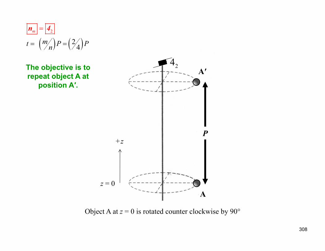
n-fold rotation followed by a translation parallel to the rotation axis P by a vector t = mP/n.
Combine rotation and translation

307
These can be difficult to visualize.
Let’s step through one:
42 screw axis
308
2
2 4
m
mt P Pn
n 4
Object A at z = 0 is rotated counter clockwise by 90°
z = 0
+z
The objective is to repeat object A at
position A′.
A
A′24
P

309
2
2 4
m
mt P Pn
n 4
Object A at z = 0 is rotated counter clockwise by 90° followed by translation parallel to z by a distance of t = 2P/4, i.e. P/2, to create object B
t
A′
A
24
B 1
90°

310
2
2 4
m
mt P Pn
n 4
Object B is rotated counter clockwise by 90° and translated parallel to z by a distance of t = P/2, producing object C
90°t
A′24
A
B
C2

311
2
2 4
m
mt P Pn
n 4
Object C is at now at z = P, the lattice repeat distance; thus we repeat it at z =0 (i.e., position C′)
A′24
B
C
AC′2… cont’d
312
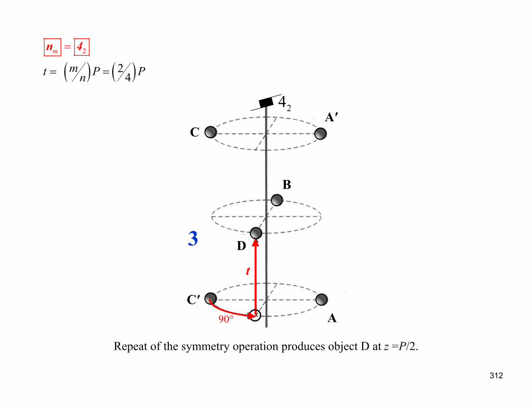
2
2 4
m
mt P Pn
n 4
Repeat of the symmetry operation produces object D at z =P/2.
A′24
A
t
C
C′
D
B
3
90°

313
2
2 4
m
mt P Pn
n 4
Repeat of the symmetry operation on object D brings everything back into coincidence
A′24
A
C
C′
D
B
4t
90°
+
+
½ +
½ +
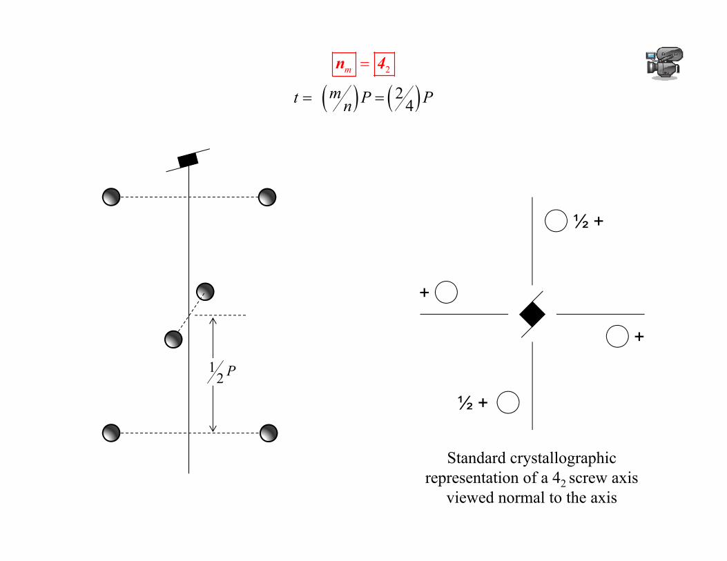
2
2 4
m
mt P Pn
n 4
12 P
Standard crystallographic representation of a 42 screw axis
viewed normal to the axis

315
Do you see things like this in real materials?

316
DNA double helix consisting of 2 anti-parallel screws
http://www.nature.com/scitable/nated/content/24263/sadava_11_8_large_2.jpg
317
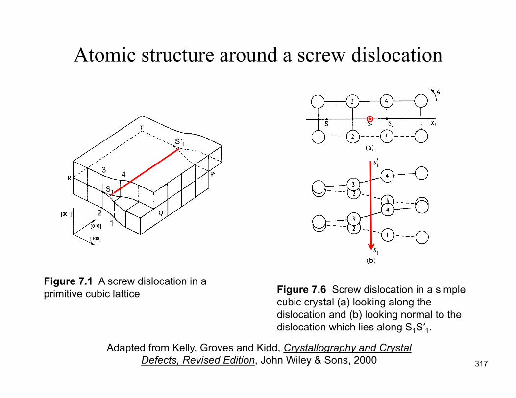
Atomic structure around a screw dislocation
Figure 7.1 A screw dislocation in a primitive cubic lattice Figure 7.6 Screw dislocation in a simple
cubic crystal (a) looking along the dislocation and (b) looking normal to the dislocation which lies along S1S′1.
S′1
12
3 4
S1
Adapted from Kelly, Groves and Kidd, Crystallography and Crystal Defects, Revised Edition, John Wiley & Sons, 2000
1s
1s

http://www.flickr.com/photos/l2xy2/4644933597/sizes/o/in/photostream/

319
The chains in the crystal structure of tellurium along the 31-screw axis. The chain is highlighted in blue colors where the dark blue atom is situated on c = 1/3, middle blue on c = 2/3 and light blue on c = 0. Thick red bonds represent covalent bonds between atoms in the chain (d = 284 pm), dashed green bonds secondary contacts between chains (d = 349 pm) and dashed purple bonds represent the hexagonal surrounding within a "layer" of tellurium (d = 446 pm).
http://www.periodictable.com/Elements/052/index.htmlhttp://en.wikipedia.org/wiki/File:Te_chains.png