Embed Size (px)
Citation preview
ANALYTICAL OPTIMIZATION OF SIMPLE ROOF SHADING DEVICES
Khaled Nassar1and Mohamed Aly1 1The American University in Cairo
line below should be left
ABSTRACT Parametric and algorithmic design tools have developed significantly in the last few years with the advent of several commercial and open-source applications and simulation software. These tools have been used extensively in the design and analysis of various building elements such as glazing, screens, massing and shading devices. Typically, ether iterative, parametric or optimization techniques are coupled with simulation software to reach an optimum design for the considered element. Setting up these problems usually requires time and effort, but sometime the designers need a simple tool to design particular elements. This paper presents an analytic approach for designing simple roof shading devices. The proposed approach is based on a ground-up analysis of the shading device geometry to reach global optimum designs for the elements. The approach is applied to a simple roof shading element and it is shown how different objectives and situations can be modelled using this approach. The results are compared to ENERGY PLUS simulations to verify the results. It is shown that comparable results can be achieved with the proposed approach without the need for the numerical simulation and in less time.
INTRODUCTION In warm climates it is often important to protect of the building from unwanted solar gain as a key part of any cooling strategy which is most readily achieved by blocking the sun’s rays before they reach the building (R. Mc Cluney, 1990). It has been shown repeatedly that concrete roof slabs without thermal insulation lead to thermal stress resulting in negative effects on the thermal comfort of the occupants (Garde et al,. 2005). Effective Shading is an excellent option for controlling solar radiation and reducing the amount of heat gain in buildings. By blocking both the direct and diffuse solar radiation they offer great passive potential in hot environments where cooling loads are significant, while movable shading addresses nocturnal radiation in night hours A number of publications addressed the effect of shading wall openings, such as windows, on energy consumption (Sherif et al., 2011), while other publications examine the dependence of the thermal
loads reduction on the size of solar shading systems (Franzetti et al., 2004), (Afnor, 2003) and (Kuhn et al., 2000). Garde (2005) provides a comprehensive list of various research efforts on designing shading devices. Liangliang et al 2012 investigated the rotation of an integrated solar panel (BIPV) in a shading device in Hong Kong. In order to maximize the energy generated while reducing the solar radiation different tilt angles were explored. The simulation results showed that the shading device BIPV did significantly increase the total energy benefits relative to PV modules. Niccolò et al (2012) developed an algorithm to design a dynamic solar shading system for an office building situated in Milan, Italy. The study aimed to define the analytical method for defining the optimal movement profile for dynamic shading system based on the horizontal mobile blinds for indoor visual comfort. This study allowed to define the annual movement of shading devices, to customize the behaviour of every single shading device and ensure constant control of their movements. In addition a wide range of simulation tools can be used to assess the effect of shading on the various aspects of the building. These tools often require a detailed building input and some will have a significant run time. While these may be of importance in many situations, it is often the case where the designers need a simple tool to design a particular building element. Therefore, often a fully fledged simulation is not warranted and a simple design tool (in the form of a spreadsheet or an add-on) may be required. Although the many previous research efforts addressed the issue of shading devices for windows, design of roof shading devices has not received an equal amount of attention. The work presented here addresses this gap and tries to develop a tool for the design of simple roof shading devices (RSD). The goal is to design a simple tool with a user friendly interface to globally optimize very simple typologies of the RSD. In the next section a formulation of the RSD problem is presented.
Proceedings of BS2013: 13th Conference of International Building Performance Simulation Association, Chambéry, France, August 26-28
- 419 -
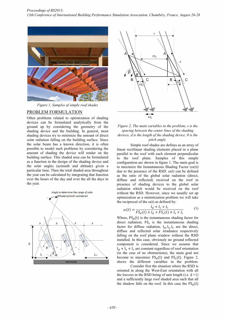
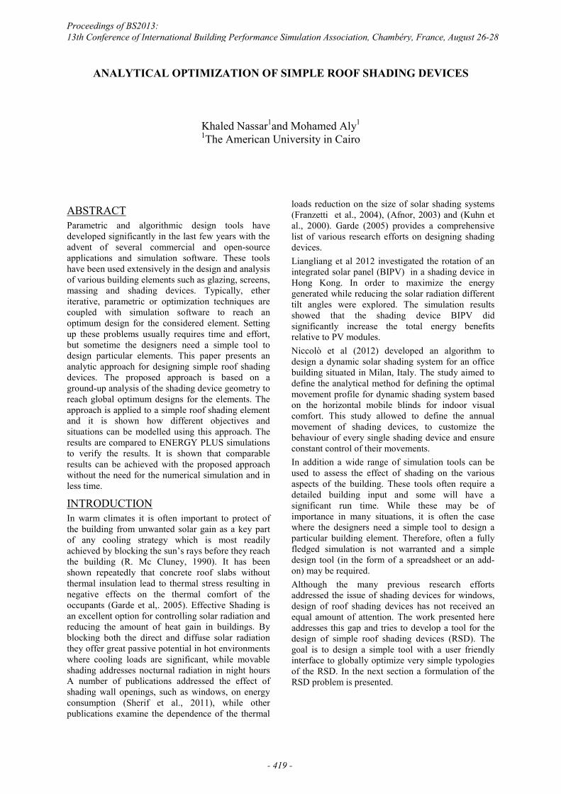
Figure 1, Samples of simple roof shades
PROBLEM FORMULATION Often problems related to optimization of shading devices can be formulated analytically from the ground up by considering the geometry of the shading device and the building. In general, most shading devices try to minimize the amount of direct solar radiation falling on the building surface. Since the solar beam has a known direction, it is often possible to model such problems by considering the amount of shading the device will render on the building surface. This shaded area can be formulated as a function in the design of the shading device and the solar angles (azimuth and altitude) given a particular time. Then the total shaded area throughout the year can be calculated by integrating that function over the hours of the day and over the all the days in the year.
Figure 2, The main variables in the problem; s is the
spacing between the center lines of the shading GHYLFHV��G�LV�WKH�OHQJWK�RI�WKH�VKDGLQJ�GHYLFH��ș�LV�WKH�
pitch angle. Simple roof shades are defines as an array of linear rectilinear shading elements placed in a plane parallel to the roof with each element perpendicular to the roof plane. Samples of this simple configuration are shown in figure 1. The main goal is WR�PD[LPL]H�WKH�,QVWDQWDQHRXV�6KDGLQJ�)DFWRU��Ȧ�W���GXH�WR�WKH�SUHVHQFH�RI�WKH�56'��Ȧ�W��FDQ�EH�GHILQHG�as the ratio of the global solar radiation (direct, diffuse and reflected) received on the roof in presence of shading devices to the global solar radiation which would be received on the roof without the RSD. However, since we usually set up optimization as a minimization problem we will take the UHFLSURFDO�RI�WKH�Ȧ�W��DV�GHILQHG�E\�
𝜔(𝑡) = 𝐼 + 𝐼 + 𝐼𝐹𝑆 (𝑡) × 𝐼 + 𝐹𝑆 (𝑡) × 𝐼 + 𝐼 (1)
Where, FS (t) is the instantaneous shading factor for direct radiation; FS is the instantaneous shading factor for diffuse radiation; I , I , I are the direct, diffuse and reflected solar irradiance respectively falling on the roof plane window without the RSD installed. In this case, obviously no ground reflected component is considered. Since we assume that I + I + I are constant regardless of roof orientation (in the case of no obstructions), the main goal not become to maximize FS (t) and FS (t). Figure 2, shows the different variables in the problem. Consider first the situation where the RSD is oriented in along the West-East orientation with all the louvers in the RSD being of unit length (i.e. d =1) and a sufficiently large roof shaded area such that all the shadow falls on the roof. In this case the FS (t)
Proceedings of BS2013: 13th Conference of International Building Performance Simulation Association, Chambéry, France, August 26-28
- 420 -
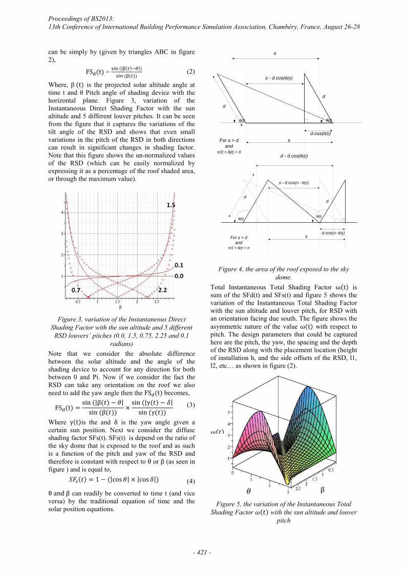
can be simply by (given by triangles ABC in figure 2),
FS (t) = (| ( ) |) ( ( )) (2)
:KHUH�� ȕ (t) is the projected solar altitude angle at WLPH� W� DQG� ș� 3LWFK� DQJOH� RI� VKDGLQJ� GHYLFH�ZLWK� WKH�horizontal plane. Figure 3, variation of the Instantaneous Direct Shading Factor with the sun altitude and 5 different louver pitches. It can be seen from the figure that it captures the variations of the tilt angle of the RSD and shows that even small variations in the pitch of the RSD in both directions can result in significant changes in shading factor. Note that this figure shows the un-normalized values of the RSD (which can be easily normalized by expressing it as a percentage of the roof shaded area, or through the maximum value).
Figure 3, variation of the Instantaneous Direct
Shading Factor with the sun altitude and 5 different RSD louvers’ pitches (0.0, 1.5, 0.75, 2.25 and 0.1
radians) Note that we consider the absolute difference between the solar altitude and the angle of the shading device to account for any direction for both between 0 and Pi. Now if we consider the fact the RSD can take any orientation on the roof we also need to add the yaw angle then the FS (t) becomes,
FS (t) = sin (|β(𝑡) − 𝜃|sin (β(𝑡)) × sin (|γ(𝑡) − 𝛿|
sin (γ(𝑡)) (3)
Where γ(t)is the and δ is the yaw angle given a certain sun position. Next we consider the diffuse shading factor SFs(t). SFs(t) is depend on the ratio of the sky dome that is exposed to the roof and as such is a function of the pitch and yaw of the RSD and therefore is constant with respect to θ or β (as seen in figure ) and is equal to,
𝑆𝐹 (𝑡) = 1 − (|cos𝜃| × |cos 𝛿|) (4)
θ and β can readily be converted to time t (and vice versa) by the traditional equation of time and the solar position equations.
s - d.cos(ș(t))
d
ș(t)
d
s
sd.cos(ș(t))
For s > dand
ʌ/2 > ș(t) > 0
ș(t)
d - d.cos(ș(t))
s - d.cos(ʌ�- ș(t))
d
ș(t)
d
sd.cos(ʌ- ș(t))
For s > dand
ʌ/2 > ș(t) > ʌ
ș(t)
Figure 4, the area of the roof exposed to the sky
dome. Total Instantaneous Total Shading Factor ω(t) is sum of the SFd(t) and SFs(t) and figure 5 shows the variation of the Instantaneous Total Shading Factor with the sun altitude and louver pitch, for RSD with an orientation facing due south. The figure shows the asymmetric nature of the value ω(t) with respect to pitch. The design parameters that could be captured here are the pitch, the yaw, the spacing and the depth of the RSD along with the placement location (height of installation h, and the side offsets of the RSD, l1, l2, etc… as shown in figure (2).
Figure 5, the variation of the Instantaneous Total
Shading Factor 𝜔(𝑡) with the sun altitude and louver pitch
𝜔(𝑡)
𝜃 β
Proceedings of BS2013: 13th Conference of International Building Performance Simulation Association, Chambéry, France, August 26-28
- 421 -
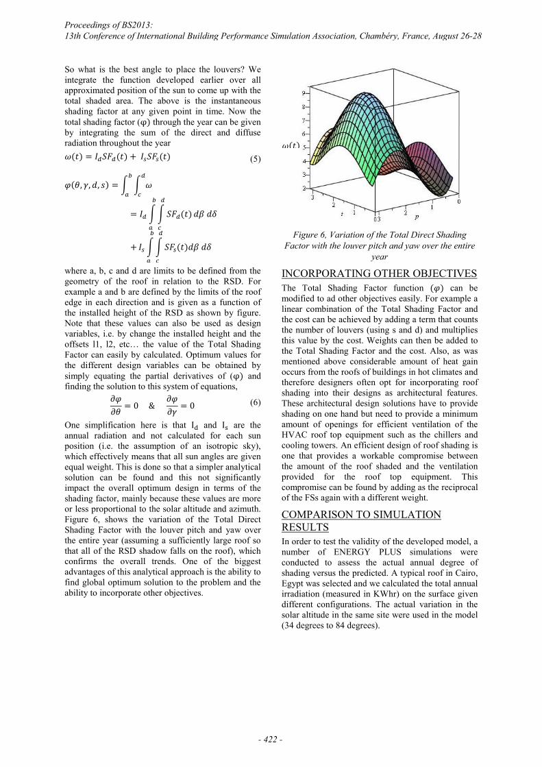
So what is the best angle to place the louvers? We integrate the function developed earlier over all approximated position of the sun to come up with the total shaded area. The above is the instantaneous shading factor at any given point in time. Now the total shading factor (φ) through the year can be given by integrating the sum of the direct and diffuse radiation throughout the year 𝜔(𝑡) = 𝐼 𝑆𝐹 (𝑡) + 𝐼 𝑆𝐹 (𝑡)
𝜑(𝜃, 𝛾,𝑑, 𝑠) = 𝜔
= 𝐼 𝑆𝐹 (𝑡)𝑑𝛽 𝑑𝛿
+ 𝐼 𝑆𝐹 (𝑡)𝑑𝛽 𝑑𝛿
(5)
where a, b, c and d are limits to be defined from the geometry of the roof in relation to the RSD. For example a and b are defined by the limits of the roof edge in each direction and is given as a function of the installed height of the RSD as shown by figure. Note that these values can also be used as design variables, i.e. by change the installed height and the offsets l1, l2, etc… the value of the Total Shading Factor can easily by calculated. Optimum values for the different design variables can be obtained by simply equating the partial derivatives of (φ) and finding the solution to this system of equations,
𝜕𝜑𝜕𝜃 = 0 & 𝜕𝜑𝜕𝛾 = 0 (6)
One simplification here is that I and I are the annual radiation and not calculated for each sun position (i.e. the assumption of an isotropic sky), which effectively means that all sun angles are given equal weight. This is done so that a simpler analytical solution can be found and this not significantly impact the overall optimum design in terms of the shading factor, mainly because these values are more or less proportional to the solar altitude and azimuth. Figure 6, shows the variation of the Total Direct Shading Factor with the louver pitch and yaw over the entire year (assuming a sufficiently large roof so that all of the RSD shadow falls on the roof), which confirms the overall trends. One of the biggest advantages of this analytical approach is the ability to find global optimum solution to the problem and the ability to incorporate other objectives.
Figure 6, Variation of the Total Direct Shading
Factor with the louver pitch and yaw over the entire year
INCORPORATING OTHER OBJECTIVES The Total Shading Factor function (𝜑) can be modified to ad other objectives easily. For example a linear combination of the Total Shading Factor and the cost can be achieved by adding a term that counts the number of louvers (using s and d) and multiplies this value by the cost. Weights can then be added to the Total Shading Factor and the cost. Also, as was mentioned above considerable amount of heat gain occurs from the roofs of buildings in hot climates and therefore designers often opt for incorporating roof shading into their designs as architectural features. These architectural design solutions have to provide shading on one hand but need to provide a minimum amount of openings for efficient ventilation of the HVAC roof top equipment such as the chillers and cooling towers. An efficient design of roof shading is one that provides a workable compromise between the amount of the roof shaded and the ventilation provided for the roof top equipment. This compromise can be found by adding as the reciprocal of the FSs again with a different weight.
COMPARISON TO SIMULATION RESULTS In order to test the validity of the developed model, a number of ENERGY PLUS simulations were conducted to assess the actual annual degree of shading versus the predicted. A typical roof in Cairo, Egypt was selected and we calculated the total annual irradiation (measured in KWhr) on the surface given different configurations. The actual variation in the solar altitude in the same site were used in the model (34 degrees to 84 degrees).
𝜔(𝑡)
Proceedings of BS2013: 13th Conference of International Building Performance Simulation Association, Chambéry, France, August 26-28
- 422 -
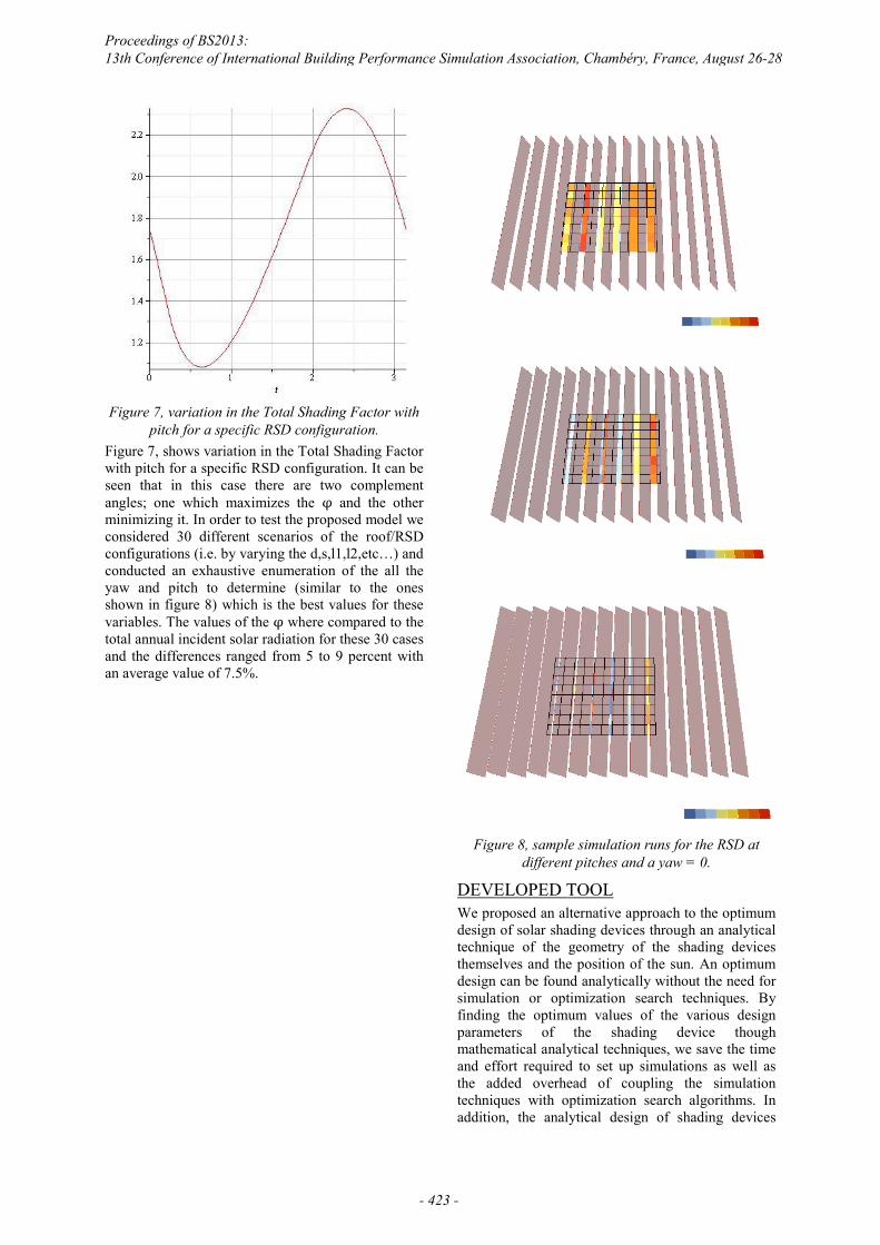
Figure 7, variation in the Total Shading Factor with
pitch for a specific RSD configuration. Figure 7, shows variation in the Total Shading Factor with pitch for a specific RSD configuration. It can be seen that in this case there are two complement angles; one which maximizes the φ and the other minimizing it. In order to test the proposed model we considered 30 different scenarios of the roof/RSD configurations (i.e. by varying the d,s,l1,l2,etc…) and conducted an exhaustive enumeration of the all the yaw and pitch to determine (similar to the ones shown in figure 8) which is the best values for these variables. The values of the φ where compared to the total annual incident solar radiation for these 30 cases and the differences ranged from 5 to 9 percent with an average value of 7.5%.
Figure 8, sample simulation runs for the RSD at
different pitches and a yaw = 0.
DEVELOPED TOOL We proposed an alternative approach to the optimum design of solar shading devices through an analytical technique of the geometry of the shading devices themselves and the position of the sun. An optimum design can be found analytically without the need for simulation or optimization search techniques. By finding the optimum values of the various design parameters of the shading device though mathematical analytical techniques, we save the time and effort required to set up simulations as well as the added overhead of coupling the simulation techniques with optimization search algorithms. In addition, the analytical design of shading devices
Proceedings of BS2013: 13th Conference of International Building Performance Simulation Association, Chambéry, France, August 26-28
- 423 -
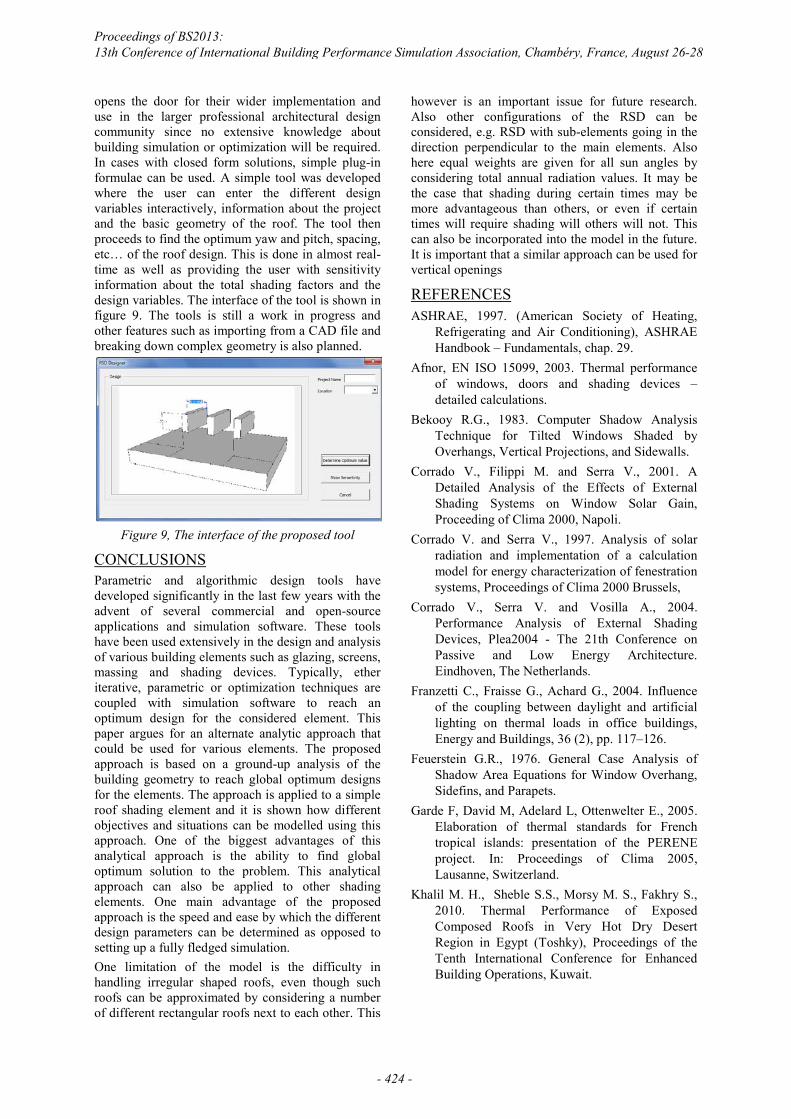
opens the door for their wider implementation and use in the larger professional architectural design community since no extensive knowledge about building simulation or optimization will be required. In cases with closed form solutions, simple plug-in formulae can be used. A simple tool was developed where the user can enter the different design variables interactively, information about the project and the basic geometry of the roof. The tool then proceeds to find the optimum yaw and pitch, spacing, etc… of the roof design. This is done in almost real-time as well as providing the user with sensitivity information about the total shading factors and the design variables. The interface of the tool is shown in figure 9. The tools is still a work in progress and other features such as importing from a CAD file and breaking down complex geometry is also planned.
Figure 9, The interface of the proposed tool
CONCLUSIONS Parametric and algorithmic design tools have developed significantly in the last few years with the advent of several commercial and open-source applications and simulation software. These tools have been used extensively in the design and analysis of various building elements such as glazing, screens, massing and shading devices. Typically, ether iterative, parametric or optimization techniques are coupled with simulation software to reach an optimum design for the considered element. This paper argues for an alternate analytic approach that could be used for various elements. The proposed approach is based on a ground-up analysis of the building geometry to reach global optimum designs for the elements. The approach is applied to a simple roof shading element and it is shown how different objectives and situations can be modelled using this approach. One of the biggest advantages of this analytical approach is the ability to find global optimum solution to the problem. This analytical approach can also be applied to other shading elements. One main advantage of the proposed approach is the speed and ease by which the different design parameters can be determined as opposed to setting up a fully fledged simulation. One limitation of the model is the difficulty in handling irregular shaped roofs, even though such roofs can be approximated by considering a number of different rectangular roofs next to each other. This
however is an important issue for future research. Also other configurations of the RSD can be considered, e.g. RSD with sub-elements going in the direction perpendicular to the main elements. Also here equal weights are given for all sun angles by considering total annual radiation values. It may be the case that shading during certain times may be more advantageous than others, or even if certain times will require shading will others will not. This can also be incorporated into the model in the future. It is important that a similar approach can be used for vertical openings
REFERENCES ASHRAE, 1997. (American Society of Heating,
Refrigerating and Air Conditioning), ASHRAE Handbook – Fundamentals, chap. 29.
Afnor, EN ISO 15099, 2003. Thermal performance of windows, doors and shading devices – detailed calculations.
Bekooy R.G., 1983. Computer Shadow Analysis Technique for Tilted Windows Shaded by Overhangs, Vertical Projections, and Sidewalls.
Corrado V., Filippi M. and Serra V., 2001. A Detailed Analysis of the Effects of External Shading Systems on Window Solar Gain, Proceeding of Clima 2000, Napoli.
Corrado V. and Serra V., 1997. Analysis of solar radiation and implementation of a calculation model for energy characterization of fenestration systems, Proceedings of Clima 2000 Brussels,
Corrado V., Serra V. and Vosilla A., 2004. Performance Analysis of External Shading Devices, Plea2004 - The 21th Conference on Passive and Low Energy Architecture. Eindhoven, The Netherlands.
Franzetti C., Fraisse G., Achard G., 2004. Influence of the coupling between daylight and artificial lighting on thermal loads in office buildings, Energy and Buildings, 36 (2), pp. 117–126.
Feuerstein G.R., 1976. General Case Analysis of Shadow Area Equations for Window Overhang, Sidefins, and Parapets.
Garde F, David M, Adelard L, Ottenwelter E., 2005. Elaboration of thermal standards for French tropical islands: presentation of the PERENE project. In: Proceedings of Clima 2005, Lausanne, Switzerland.
Khalil M. H., Sheble S.S., Morsy M. S., Fakhry S., 2010. Thermal Performance of Exposed Composed Roofs in Very Hot Dry Desert Region in Egypt (Toshky), Proceedings of the Tenth International Conference for Enhanced Building Operations, Kuwait.
Proceedings of BS2013: 13th Conference of International Building Performance Simulation Association, Chambéry, France, August 26-28
- 424 -
Kuhn T.E., Hler C.B., Platze W.J., 2000. Evaluation of overheating protection with sun-shading systems, Solar Energy, 69 (1) pp. 59–74.
Liangliang Sun, Lin Lu, Hongxing Yang, Optimum design of shading-type building-integrated photovoltaic claddings with different surface azimuth angles, Applied Energy, Volume 90, Issue 1, February 2012, Pages 233-240, ISSN 0306-2619, 10.1016/j.apenergy.2011.01.062.
Mc Cluney R., 1990. Awning shading algorithm update, ASHRAE Transactions, vol. 96, Part 1.
Niccolò Aste, Rajendra Singh Adhikari, Claudio Del Pero, An Algorithm for Designing Dynamic Solar Shading System, Energy Procedia, Volume 30, 2012, Pages 1079-1089, ISSN 1876-6102, 10.1016/j.egypro.2012.11.121.
Sherif A., El-Deeb K., El Zafarany A. and Aly M., 2011. Effectiveness of External Wall Shading in Reducing the Energy Consumption of Desert Buildings, ICSDC 2011.
Proceedings of BS2013: 13th Conference of International Building Performance Simulation Association, Chambéry, France, August 26-28
- 425 -