Embed Size (px)
Citation preview

Analytical procedure for stress field solution in concretegravity dams
Paulo Marcelo Vieira Ribeiro and Lineu José PedrosoDepartment of Civil and Environmental Engineering,University of Brasilia - UnB, Brasilia, DF – Brazil
Abstract
Analytical solutions are of great interest to designers of concrete dams. Even though it is possible to solvethis problem with numerical methods, it is undeniable the contribution of a totally analytical interior stresssolution of dams. The easiness of computational planning and interpretation of this procedure, besides thespeed and quality of the results obtained when compared to numerical solutions, justify the use of this methodfor preliminary stress analysis in concrete gravity dams.
The analytical proposed development is based on classical formulations of solid mechanics and equilibriumof cross sections along the structure – assimilated to a deep beam – for a 2-D plane strain problem. Theseismic loads associated to inertia and hydrodynamic forces are evaluated by a Pseudo-Static procedure, andare applied as static equivalent forces, which makes easier the analytical solution of this problem.
The procedure development will be presented in this work, besides several examples and applicationsobtained through a computational tool developed by the Dynamics and Fluid-Structure Interaction Group(DFSG) at University of Brasilia. The results show a great potential of this solution applied to solid mechan-ics problems in engineering of dams, and indicates good results when compared to formulations and designexamples obtained from USBR (United States Bureau of Reclamation).
Keywords: analytical, concrete, dams, seismic, stress
1 Introduction
It is well known that a closed form stress field solution for concrete gravity dams is a challenge tostructural engineers. The arbitrary shape and loads applied in this geometry turns the design into amulti-variable task. Numerical solutions for this problem are available, but it is undeniable that ananalytical procedure is of great interest to structural designers.
The Gravity Method [1] is a solution proposed by the United States Bureau of Reclamation (USBR)for design of concrete gravity dams. In-plane stresses are results of this procedure. They can be easilycombined for principal stress analysis at any interior point of the given geometry. It is a great design
Mechanics of Solids in Brazil 2007, Marcílio Alves & H.S. da Costa Mattos (Editors)Brazilian Society of Mechanical Sciences and Engineering, ISBN 978-85-85769-30-7

470 P.M.V. Ribeiro and L.J. Pedroso
tool, but the mid-steps of this procedure are not very clear in literature, and that implies that thevalid boundaries of this solution can be become a problem to designers.
Past works developed by the DFSG have made important achievements in an attempt to solveanalytically this problem [2–4]. A complete rebuild of this method was proposed by Ribeiro [5]. It hasbeen shown that final formulations, including Static and Pseudo-Static procedures, are identical tothe original ones given by USBR. A forward step, including a new type of analysis is now available,and it gives this method additional seismic solution, including a modified pseudo-dynamic approachfor stress field determination. A computer code called SAGDAM (Stress Analysis of Gravity Dams)developed by the DFSG is able to solve the stress field including both static and seismic actions in adam.
The easiness of computational planning of this procedure and quality of the results obtained whencompared to finite element method models makes this solution a very powerful tool for initial designof concrete gravity dams. The step-by-step procedure and some practical examples are presented inthis work.
2 Exterior actions in a dam
Dams are usually subjected, in normal operation conditions, to three major exterior actions: self-weight, hydrostatic and uplift pressures (Figure 1). During an earthquake seismic loads must be alsotaken in account, and these include the hydrodynamic and inertia effects (estimated under a specifiedlevel of seismic analysis; Pseudo-Static in example).
Figure 1: Arbitrary section over normal operation actions (static analysis)
Mechanics of Solids in Brazil 2007, Marcílio Alves & H.S. da Costa Mattos (Editors)Brazilian Society of Mechanical Sciences and Engineering, ISBN 978-85-85769-30-7

Analytical procedure for stress field solution in concrete gravity dams 471
Figure 2: Pseudo-Static actions in a dam (seismic analysis)
3 Analytical equations (normal operation actions)
Stresses formulations on arbitrary sections are listed in the next items. This analytical developmentis based on classical Theory of Elasticity 2D, under some simplified hypotheses, and the idea of globalequilibrium of forces used in Strength of Materials.
3.1 Simplified hypotheses
The stress field solution is based on the following properties:1. Linear stress distribution for vertical normal and parabolic shear stress distributions over the
section in analysis;2. The dam is built of a homogeneous, isotropic and linear elastic concrete;3. All applied loads are transferred to foundation under beam action. This means that the dam is
analyzed as a cantilever beam with unitary width;4. The dam’s body is divided in concrete joints that have uniform properties along its length, and
are uniformly elastic;5. There is no interaction between adjacent joints. Each one is treated independently.
3.2 Vertical normal stress formulation (σZ )
From classical beam theory, assuming that normal stresses are linear distributed over a section, it isshown that:
σZ =ΣW
A+
ΣM · yI
(1)
Equation (1) can be rearranged to a coordinate system fixed at the dam’s downstream position (y).That implies on the following equation:
σZ (y) =(
ΣW
T− 6 · ΣM
T 2
)+
(12 · ΣM
T 3
)· y (2)
Mechanics of Solids in Brazil 2007, Marcílio Alves & H.S. da Costa Mattos (Editors)Brazilian Society of Mechanical Sciences and Engineering, ISBN 978-85-85769-30-7

472 P.M.V. Ribeiro and L.J. Pedroso
where:ΣW = sum of all vertical forces over an analyzed section;ΣM = sum of all moments over an analyzed section;T = length of the section being analyzed;y = distance measured from section’s downstream side;
Figure 3 illustrates the signal convention for stresses and forces over a section.
σ
σ
τ
τ (b)(a)
Figure 3: Positive stresses (a) and forces (b) over a section
3.3 Shear stress formulation (τY Z or τZY )
It is assumed that shear stresses follow a second degree parabolic equation:
τZY (y) = a1 + b1 · y + c1 · y2 (3)
where a1,b1 and c1 are specific constants for every section in analysis.Three boundary conditions are needed for this problem. Two of them can be obtained at the dam’s
upstream and downstream sides. The last one is given by the shear force acting on a section. Thesolution of these constants leads to the following final equation for shear stresses:
τZY (y) = τZY D− 1T·[6 · ΣV
T+ 2 · τZY U + 4 · τZY D
]·y+
1T 2·[6 · ΣV
T+ 3 · τZY D ·+3 · τZY U
]·y2 (4)
where:ΣV = sum of all horizontal forces over an analyzed section;τZY U = shear stress at dam’s upstream side, given by Equation (5);
Mechanics of Solids in Brazil 2007, Marcílio Alves & H.S. da Costa Mattos (Editors)Brazilian Society of Mechanical Sciences and Engineering, ISBN 978-85-85769-30-7
Analytical procedure for stress field solution in concrete gravity dams 473
τZY D = shear stress at dam’s downstream side, given by Equation (6);
τZY U = −[σZU − p] · tan (φU ) (5)
τZY D = [σZD − p′] · tan (φD) (6)
σZU = vertical normal stress at dam’s upstream side (y = T ), given by Equation (2);σZD = vertical normal stress at dam’s downstream side (y = 0), given by Equation (2);p or p′ = hydrostatic pressure at section’s upstream or downstream side;φU or φD = angle between upstream or downstream side and a vertical line.
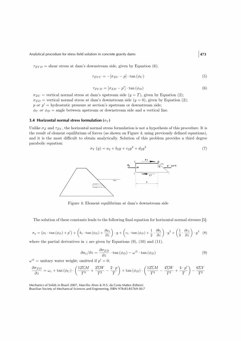
3.4 Horizontal normal stress formulation (σY )
Unlike σZ and τZY , the horizontal normal stress formulation is not a hypothesis of this procedure. It isthe result of element equilibrium of forces (as shown on Figure 4; using previously defined equations),and it is the most difficult to obtain analytically. Solution of this problem provides a third degreeparabolic equation:
σY (y) = a2 + b2y + c2y2 + d2y
3 (7)
yσ E2E1y FE DC dz p´.cos φDφDds
Figure 4: Element equilibrium at dam’s downstream side
The solution of these constants leads to the following final equation for horizontal normal stresses [5]:
σy =(a1 · tan (φD) + p′
)+
(b1 · tan (φD) +
∂a1
∂z
)· y +
(c1 · tan (φD) +
1
2· ∂b1
∂z
)· y2 +
(1
3· ∂c1
∂z
)· y3 (8)
where the partial derivatives in z are given by Equations (9), (10) and (11).
∂a1/∂z =∂σZD
∂z· tan (φD)− ω⊗ · tan (φD) (9)
ω⊗ = unitary water weight; omitted if p′ = 0;
∂σZD
∂z= ωc + tan (φU ) ·
(12ΣM
T 3+
2ΣW
T 2− 2 · p
T
)+ tan (φD) ·
(12ΣM
T 3− 4ΣW
T 2+
4 · p′T
)− 6ΣV
T 2
Mechanics of Solids in Brazil 2007, Marcílio Alves & H.S. da Costa Mattos (Editors)Brazilian Society of Mechanical Sciences and Engineering, ISBN 978-85-85769-30-7

474 P.M.V. Ribeiro and L.J. Pedroso
ωc = unitary concrete weight;
∂b1
∂z= − 1
T 2·[6 ·
(∂ΣV
∂z
)− ∂T
∂z·(
12 · ΣV
T+ 2 · τZY U + 4 · τZY D
)]− 1
T·[2 ·
(∂τZY U
∂z
)+ 4 ·
(∂τZY D
∂z
)]
(10)
∂ΣV
∂z= p′ − p
∂T
∂z= tan (φU ) + tan (φD)
∂τZY D
∂z=
∂a1
∂z
∂τZY U
∂z= −∂σZU
∂z· tan (φU ) + ω⊗ · tan (φU )
ω⊗ = unitary water weight; omitted if p = 0;
∂σZU
∂z= ωc + tan (φU ) ·
(4 · pT
− 4ΣW
T 2− 12ΣM
T 3
)+ tan (φD) ·
(2ΣW
T 2− 2 · p′
T− 12ΣM
T 3
)+
6ΣV
T 2
∂c1
∂z=
1
T 3·[6 ·
(∂ΣV
∂z
)− ∂T
∂z·(
18 · ΣV
T+ 6 · τZY U + 6 · τZY D
)]+
1
T 2·[3 ·
(∂τZY U
∂z
)+ 3 ·
(∂τZY D
∂z
)]
(11)Equations (2) and (4), combined with (7) and its constants, gives the stress field solution for a
dam under normal operation condition. That is: under self-weight plus hydrostatic pressures actingon upstream and downstream sides. Uplift pressures contribution is not included.
4 Analytical equations (pseudo-static actions)
Comments on seismic action of inertia and hydrodynamic effects using pseudo-static approach onprevious formulations are listed in the next items.
4.1 Procedure hypotheses
The pseudo-static approach for analysis of dams follows the following hypotheses:1. Rigid dam movement (uniformly accelerated over its height);2. Incompressible fluid.
4.2 Additional forces
In this procedure additional forces appear due to inertia and hydrodynamic effects on a rigid bodymovement in an incompressible fluid. Inertia contribution is given by IF = m · vH , where m is thestructural mass over an analyzed section, and vH is the rigid body acceleration. Hydrodynamic effectsare calculated though a simplified Westergaard [6] formula, given by Equation (12).
Mechanics of Solids in Brazil 2007, Marcílio Alves & H.S. da Costa Mattos (Editors)Brazilian Society of Mechanical Sciences and Engineering, ISBN 978-85-85769-30-7

Analytical procedure for stress field solution in concrete gravity dams 475
pe (h) =0, 5430, 583
· 78· γ · Vg ·
√H · h (12)
where:pe = hydrodynamic pressure along the fluid-structure interface;
γ = unitary fluid weight;
Vg = horizontal seismic acceleration in terms of gravity acceleration (vH/g);
H = reservoir height;
h = vertical distance between analyzed section and reservoir surface.
Hydrodynamic pressure distribution is illustrated on Figure 2.Equation’s (12) integral over h provides the hydrodynamic force over an analyzed section.
FHD =
h∫
0
0, 5430, 583
· 78· Vg · γ ·
√H · h dh =
23· 0, 5430, 583
· 78Vg · γ ·
√H · h1,5 (13)
4.3 Vertical normal stress formulation (σZ )
Equation (2) remains the same in this analysis. But moments and forces are increased by additionalinertia and hydrodynamic effects.
4.4 Shear stress formulation (τY Z or τZY )
Equation (4) remains valid, but τZY U and τZY D are modified by the presence of hydrodynamic pressureterms (pe and p′e) on its equations (Figure 5):
τY ZU = τZY U = −[σZU − p± ††pe] · tan (φU ) (14)
τY ZD = τZY D = [σZD − p′ ± †p′e] · tan (φD) (15)
where:pe = upstream hydrodynamic pressure on a section, given by Westergaard formula;p′e = downstream hydrodynamic pressure on a section, given by Westergaard;†† = positive for downstream acceleration, otherwise negative;† = positive for upstream acceleration, otherwise negative.
Forces and moments are increased by additional inertia and hydrodynamic effects.
Mechanics of Solids in Brazil 2007, Marcílio Alves & H.S. da Costa Mattos (Editors)Brazilian Society of Mechanical Sciences and Engineering, ISBN 978-85-85769-30-7

476 P.M.V. Ribeiro and L.J. Pedroso YZD ZYDYZUZYU τ
τφDφDDφ
σZDZU σ dydz dsds dzdyφUφU Uφ
(p+pe).sen(p+pe).cosσ
σ
τ
τ
(p´+pe´).sen(p´+pe´).cos
Figure 5: Element equilibrium at upstream and downstream sides
4.5 Horizontal normal stress formulation (σY )
Element equilibrium shown on Figure 5 receives two additional components: inertia and hydrodynamicforces. Constants a2 and b2 suffer the following modifications:
a2 = a1 tan (φD) + p′ ± ††p′e (16)
b2 = b1 tan (φD) + ∂a1/∂z ± ††λ · ωc (17)
where:λ = vh/g = horizontal acceleration modulus divided by gravity acceleration;
Constants c2 and d2 do not receive additional terms on its formulations. However the partial deriva-tives in zare affected by seismic action. The first one is given by:
∂a1
∂z=
(∂σZD
∂z− ω⊗ ± †∂p′e
∂z
)· tan (φD) (18)
∂σZD
∂z=ωc + tan (φU ) ·
(12ΣM
T 3+
2ΣW
T 2− 2 · p
T± ††2 · pe
T
)
+ tan (φD) ·(
12ΣM
T 3− 4ΣW
T 2+
4 · p′T
± ††4 · p′e
T
)− 6ΣV
T 2
(19)
where ∂p′e/∂z is the first hydrodynamic downstream pressure derivative.Equation (10) remains the same for ∂b1/∂z, but inside terms suffer the following modifications:
∂ΣV
∂z= − (p− p′ ± †λ · ωc · T ± †pe ± †p′e) (20)
∂τZY D
∂z=
∂a1
∂z=
(∂σZD
∂z− ω⊗ ± †∂p′e
∂z
)· tan (φD) (21)
Mechanics of Solids in Brazil 2007, Marcílio Alves & H.S. da Costa Mattos (Editors)Brazilian Society of Mechanical Sciences and Engineering, ISBN 978-85-85769-30-7

Analytical procedure for stress field solution in concrete gravity dams 477
∂τZY U
∂z=
(ω⊗ − ∂σZU
∂z± †∂pe
∂z
)· tan (φU ) (22)
∂σZU
∂z=ωc + tan (φU ) ·
(4 · pT
± †4 · pe
T− 4ΣW
T 2− 12ΣM
T 3
)
+ tan (φD) ·(
2ΣW
T 2± †2 · p
′e
T− 2 · p′
T− 12ΣM
T 3
)+
6ΣV
T 2
(23)
Equation (11) remains the same for ∂c1/∂z. Modifications on inside terms have already been shownon above equations. It is important to notice that all equations on seismic effects action must includeforces and moments with inertia and hydrodynamic contributions. Except when commented, all termsremains the same and have the same meaning as in the static case.
5 Analytical procedure valid boundaries
The proposed procedure was compared with results obtained in a finite element model. Valid bound-aries of this solution are presented in the next items.
5.1 Dam geometry and finite element mesh properties
Figure 6: Friant Dam typical section geometry
Mechanics of Solids in Brazil 2007, Marcílio Alves & H.S. da Costa Mattos (Editors)Brazilian Society of Mechanical Sciences and Engineering, ISBN 978-85-85769-30-7

478 P.M.V. Ribeiro and L.J. Pedroso
Figure 6 illustrates the analyzed dam. It is a real model of American Friant Dam under normaloperation actions (except uplift forces). The finite element mesh was built using eight node planestrain quadrilaterals elements (Figure 7). In this analysis the foundation has the same material andelement properties as the dam’s body.
Figure 7: Friant Dam finite element model [7]
5.2 Overall comparison of results
Figures 8 and 9 illustrate an overall comparison of principal stress results under normal operationactions (except uplift forces).
(a) (b)
Figure 8: Maximum principal stresses (kPa) obtained analytically (a) and with finite elementmethod (b)
Mechanics of Solids in Brazil 2007, Marcílio Alves & H.S. da Costa Mattos (Editors)Brazilian Society of Mechanical Sciences and Engineering, ISBN 978-85-85769-30-7

Analytical procedure for stress field solution in concrete gravity dams 479
(a) (b)
Figure 9: Minimum principal stresses (kPa) obtained analytically (a) and with finite elementmethod (b)
5.3 Section results
Section results are presented on Figures 10 through 13. Elevation 71.63m (88% dam's height)0,00
50,00
100,00
150,00
200,00
250,00
0,0 1,0 2,0 3,0 4,0 5,0 6,0 7,0 8,0 9,0y (m)stress (kPa) SZ Analytical
TZY AnalyticalSY AnalyticalSZ FEMTZY FEMSY FEM
Figure 10: Elevation 71.63m stress distribution
Mechanics of Solids in Brazil 2007, Marcílio Alves & H.S. da Costa Mattos (Editors)Brazilian Society of Mechanical Sciences and Engineering, ISBN 978-85-85769-30-7

480 P.M.V. Ribeiro and L.J. Pedroso Elevation 41.15m (51% dam's height)0,00
100,00
200,00
300,00
400,00
500,00
600,00
700,00
800,00
0,0 5,0 10,0 15,0 20,0 25,0 30,0 35,0y (m)stress (kPa) SZ AnalyticalTZY AnalyticalSY AnalyticalSZ FEMTZY FEM
SY FEM
Figure 11: Elevation 41.15m stress distribution
Elevation 25.91m (32% dam's height)
0,00
200,00
400,00
600,00
800,00
1.000,00
1.200,00
0,0 5,0 10,0 15,0 20,0 25,0 30,0 35,0 40,0 45,0y (m)stress (kPa) SZ Analytical
TZY AnalyticalSY AnalyticalSZ FEMTZY FEMSY FEM
Figure 12: Elevation 25.91m stress distribution
Mechanics of Solids in Brazil 2007, Marcílio Alves & H.S. da Costa Mattos (Editors)Brazilian Society of Mechanical Sciences and Engineering, ISBN 978-85-85769-30-7

Analytical procedure for stress field solution in concrete gravity dams 481 Elevation 10.67m (13% dam's height)0,00
200,00
400,00
600,00
800,00
1.000,00
1.200,00
1.400,00
0,0 10,0 20,0 30,0 40,0 50,0 60,0y (m)Stress (kPa) SZ Analytical
TZY Analytical
SY Analytical
SZ FEM
TZY FEM
SY FEM
Figure 13: Elevation 10.67m stress distribution
5.4 Results analysis
From the above figures and graphics it is clear that the analytical procedure provides very goodresults for stress field distribution when compared to finite element solution. Figures 8a and 8b arealmost identical. Very good results are also shown by Figures 9a and 9b. Section analysis reveals thatanalytical stress functions are very close to numerical results on a great part of the dam’s elevations.Sections near the base or close to abrupt changes in geometry provide poor results.
6 Some seismic results samples
Seismic action is able to make significant changes on stress field magnitudes during earthquakes.Figures 14a and 14b illustrate some sample results. The first one indicates the stress field on PineFlat Dam under normal operation actions. The second one indicates the stress field during a 0.2g(1.962m
/s2) peak ground acceleration (upstream direction), using the pseudo-static approach.
7 Conclusions
Analysis of previous results indicates that:1. Analytical results are globally very similar to the ones obtained trough numerical methods as
seen in Figures 8 and 9;2. Section analysis justifies the above results. Analytical stress equations cover most of the dam’s
Mechanics of Solids in Brazil 2007, Marcílio Alves & H.S. da Costa Mattos (Editors)Brazilian Society of Mechanical Sciences and Engineering, ISBN 978-85-85769-30-7

482 P.M.V. Ribeiro and L.J. Pedroso
(a) (b)
Figure 14: Pine Flat Dam maximum principal stresses (kPa) under normal (a) and upstream seismicaction (b)
stress field with good accuracy. Singular points on geometry or near boundary conditions (dam’sbase) provide poor results;
3. The simple nature of this procedure and the good results provided makes it an ideal tool forpreliminary design of concrete dams. Computational cost when compared to the output’s qualityis minimal for automatic calculations, and that is one the method’s great advantage.
4. Seismic action can make significant changes on stress field during earthquakes. When Pine FlatDam is accelerated at upstream direction, maximum principal stresses magnitudes at down-stream side can increase up to 67%. The same effect could be expected in a downstream direction,generating overstressed regions on upstream side.
Acknowledgements
The authors are grateful for the financial support provided by CNPq and ELETRONORTE scholar-ships.
References
[1] Design of Gravity Dams. USBR (United States Bureau of Reclamation): Denver: United States Departmentof the Interior – Bureau of Reclamation, 1976.
[2] Oliveira, F.F., Análise de Tensões e Estabilidade Global de Barragens de Gravidade de Concreto. Master’sthesis, Universidade de Brasília, 2002.
[3] Léger, P. & Tinawi, R., Lecture notes of the seminars on research and development of security and structuralintegrity of concrete dams. Technical report, UM/Poly, Montreal, 2000.
Mechanics of Solids in Brazil 2007, Marcílio Alves & H.S. da Costa Mattos (Editors)Brazilian Society of Mechanical Sciences and Engineering, ISBN 978-85-85769-30-7

Analytical procedure for stress field solution in concrete gravity dams 483
[4] Silva, S.F. & Pedroso, L.J., Avaliação preliminar da segurança sísmica de um perfil típico em barragem deconcreto gravidade. Relatório técnico de pesquisa rtp-sfs1-03/05, Universidade de Brasília, Brasília, 2005.
[5] Ribeiro, P.M.V., Uma Metodologia Analítica para a Avaliação do Campo de Tensões em Barragens deConcreto durante Terremotos. Master’s thesis, Universidade de Brasília - UnB, 2006.
[6] Westergaard, H.M., Water pressure on dams during earthquakes. Transactions ASCE, 98(1835), pp. 418–433, 1933.
[7] ANSYS, versão 5.4. “Método dos Elementos Finitos” . ANSYS Inc., 1996.
Mechanics of Solids in Brazil 2007, Marcílio Alves & H.S. da Costa Mattos (Editors)Brazilian Society of Mechanical Sciences and Engineering, ISBN 978-85-85769-30-7