Embed Size (px)
Citation preview
PORT-SAID ENGINEERING RESEARCH JOURNAL
Faculty of Engineering - Port Said University
Volume 23 No.2 September 2019 pp: 1:10
1
Analytical Study for the Visual Appearance of Tensile Membrane Structure Ashraf A. Elmokadem
1, Ahmed A. Waseef
2 and Mohamed E. Elballah
3 ABSTRACT
In the past, Fri Otto designed Tensile Membrane Structures (TMS) using soap film and large physical models.
Nowadays however, complex computational methods are available and can be used to generate an optimal TMS form
that can improve the aesthetic aspect of these structures. This research paper presents a comprehensive categorization
for TMS gathering all possible present classifications. Besides, the paper discusses the factors that impact and control
the design of TMS and identifies the ones that affect the overall visual appearance and perception of TMS structures.
The paper also provides a comprehensive analysis of these identified factors to quantify their impact on the final form
of the TMS. Three case studies of TMS were analyzed to demonstrate the identified factors and their impact on the
TMS. The results revealed that the structure type and material used in TMS are the most affecting factors on the overall
image and visual perception of TMS.
Keywords: Tensile Membrane Structure, Visual Appearance, Daylighting,
Introduction: Unlike conventional building structures, TMS can be
distinguished based on their structural concept rather than
their building materials. For example, materials such as
timber, concrete, and/or steel limit designers to specific
structural systems in their designs. While in the case of
TMS, there are numerous materials that can be used in the
same structural form. For membranes, the excitement of their exterior
sculptural form, beauty of their interior space, purity of
their structural system, suitability of the materials used and
the apparent comfort of their internal climatic conditions
are the fundamentals in securing this aim.[1]
1. Tensile Membrane Structure
Modem construction technologies, such as steel and
reinforced concrete frames, seemed to release architects
from many constraints of structure. They indeed brought
larger freedoms for architects to determine architectural
forms. However, such technologies could not free
architects an example of a tensile structure is membranes,
usually constructed as a set of continuous surfaces,
carrying load through membrane action.[2] Form matters
associated with scales of construction.[3] Besides,
Membrane structures are one form of architectural features
that are becoming hugely popular within modern-day
engineering. They are becoming majorly prominent in
many designs. Although they have been used in
architecture for over 50 years, they use an Aesthetic and
ergonomic feature is becoming more apparent.[4]
A well designed tensile structure is characteristic by
structure and materials with authentic expressions.
1 Professor and Head of Architectural engineering and
urban planning faculty of engineering Port Said
University, email: [email protected]
2 Assistant Professor at Architecture department,
College of Architecture and Design, Effat University.
Assistant Professor at Architectural engineering &
urban planning dept., faculty of engineering Port Said
University, email: [email protected]
3 Demonstrator at Arab Academy for Science and
Technology port said branch.
email:[email protected]
https://dx.doi.org/10.21608/pserj.2019.49412
There is no part of the lightweight structure that is useless
or added on for any reason. Every part of these structures
is present by necessity – what you see is the essence of the
structure. There are no massive hidden structural
fortifications; nothing in the structure has been added for
decorative purposes.
These structures are catching people eyes in part because
of their obvious contrast to traditional structures. Where
conventional structures are sturdy, staid and obviously
anchored to the ground, tensile membranes are light,
graceful and sometimes give you the impression that they
could fly. They are completely different from the tall
concrete frames, the steel towers and trusses of everyday
buildings. [5]
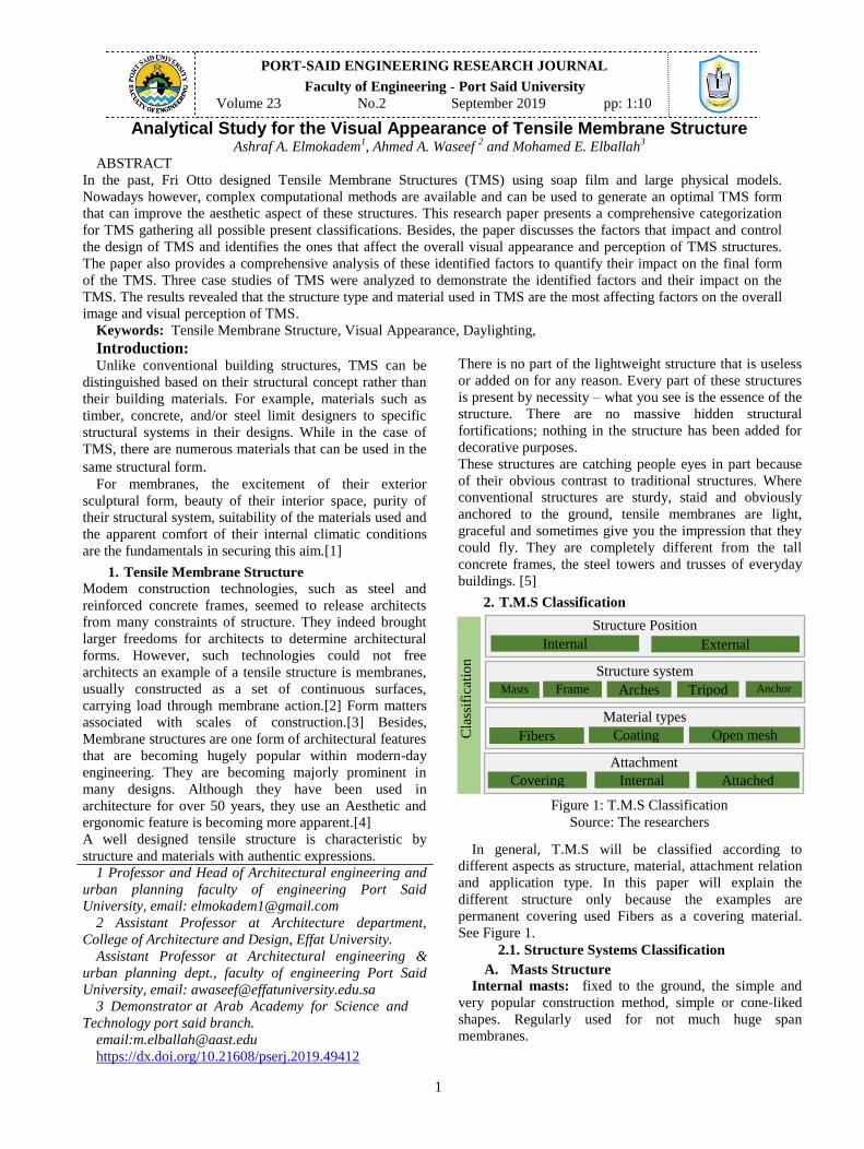
2. T.M.S Classification
In general, T.M.S will be classified according to
different aspects as structure, material, attachment relation
and application type. In this paper will explain the
different structure only because the examples are
permanent covering used Fibers as a covering material.
See Figure 1.
2.1. Structure Systems Classification
A. Masts Structure
Internal masts: fixed to the ground, the simple and
very popular construction method, simple or cone-liked
shapes. Regularly used for not much huge span
membranes.
Figure 1: T.M.S Classification
Source: The researchers
Cla
ssif
icat
ion
Structure Position
Internal External
Material types
Structure system
Fibers
Attachment
Covering Internal Attached
Open mesh Coating
Masts Frame
s
Arches Tripod
s
Anchor
2
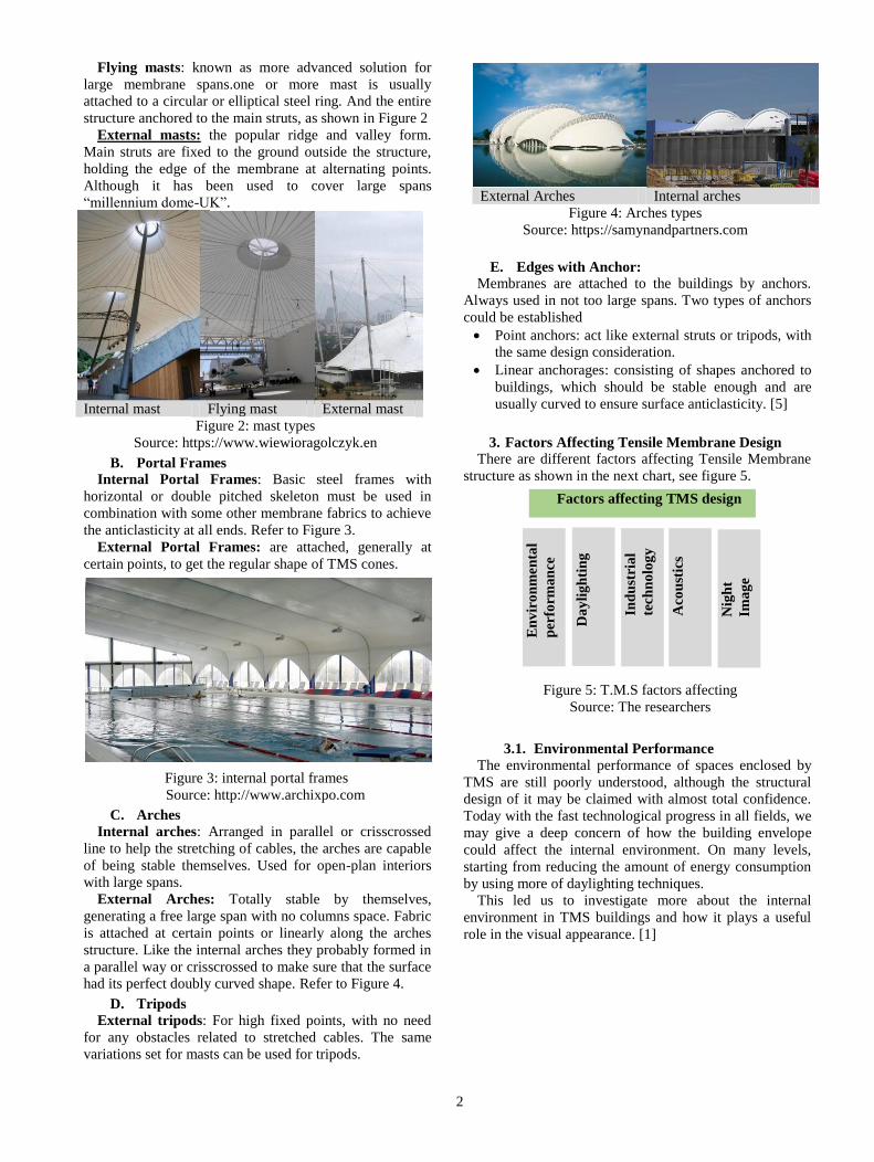
Flying masts: known as more advanced solution for
large membrane spans.one or more mast is usually
attached to a circular or elliptical steel ring. And the entire
structure anchored to the main struts, as shown in Figure 2
External masts: the popular ridge and valley form.
Main struts are fixed to the ground outside the structure,
holding the edge of the membrane at alternating points.
Although it has been used to cover large spans
“millennium dome-UK”.
Internal mast Flying mast External mast
Figure 2: mast types
Source: https://www.wiewioragolczyk.en
B. Portal Frames
Internal Portal Frames: Basic steel frames with
horizontal or double pitched skeleton must be used in
combination with some other membrane fabrics to achieve
the anticlasticity at all ends. Refer to Figure 3.
External Portal Frames: are attached, generally at
certain points, to get the regular shape of TMS cones.
C. Arches
Internal arches: Arranged in parallel or crisscrossed
line to help the stretching of cables, the arches are capable
of being stable themselves. Used for open-plan interiors
with large spans.
External Arches: Totally stable by themselves,
generating a free large span with no columns space. Fabric
is attached at certain points or linearly along the arches
structure. Like the internal arches they probably formed in
a parallel way or crisscrossed to make sure that the surface
had its perfect doubly curved shape. Refer to Figure 4.
D. Tripods
External tripods: For high fixed points, with no need
for any obstacles related to stretched cables. The same
variations set for masts can be used for tripods.
Figure 4: Arches types
Source: https://samynandpartners.com
E. Edges with Anchor:
Membranes are attached to the buildings by anchors.
Always used in not too large spans. Two types of anchors
could be established
Point anchors: act like external struts or tripods, with
the same design consideration.
Linear anchorages: consisting of shapes anchored to
buildings, which should be stable enough and are
usually curved to ensure surface anticlasticity. [5]
3. Factors Affecting Tensile Membrane Design
There are different factors affecting Tensile Membrane
structure as shown in the next chart, see figure 5.
3.1. Environmental Performance
The environmental performance of spaces enclosed by
TMS are still poorly understood, although the structural
design of it may be claimed with almost total confidence.
Today with the fast technological progress in all fields, we
may give a deep concern of how the building envelope
could affect the internal environment. On many levels,
starting from reducing the amount of energy consumption
by using more of daylighting techniques.
This led us to investigate more about the internal
environment in TMS buildings and how it plays a useful
role in the visual appearance. [1]
External Arches Internal arches
Figure 3 Figure 3: internal portal frames
Source: http://www.archixpo.com
Figure 5: T.M.S factors affecting
Source: The researchers
Factors affecting TMS design
En
vir
on
men
tal
per
form
an
ce
Da
yli
gh
tin
g
Ind
ust
ria
l
tech
no
log
y
A
cou
stic
s
Nig
ht
Ima
ge

Figure 7: Specifc Technology to install the roof of Sidi
gaber terminal
Source: Hueck max Egypt – adapted by researchers.
3
3.2. Daylighting
Bright interiors is one of the special features of
buildings using membranes as an envelope. It depends on
how translucent the membrane material is. It varies from
the amount of sunlight penetrating the internal space.
Some fabrics reaches 95% of transparency which allows
the interiors to be totally lit by the diffused sunlight,
avoiding glare problems. This unique characteristic make
TMS useful for different functions such as terminals, sport
facilities, music and theater activities. [1] See Figure 6.
Figure 6: Day lighting through Sharm el shiekh airport
terminal
Source: Hueck Max Egypt – adapted by researchers.
3.3. Industrial Technology
Now days, fabrics used in tensile structure need to high
technology process only available in limited number of
manufacturers. Due to the light weight and the adjustable
form of the fabrics used in TMS, all the manufacturing
may not happen at the construction site. Tent are
fabricated and shipped long distances to the installation
site. However, this is not an effective factor to the cost and
it’s not an obstacle for the installation, although attention
are required when it comes to wrapping, handling, and
shipping to keep away any kind of fabric material loss. [6]
Refer to Figure 7.
3.4. Acoustics
Architects can overlook acoustics in designing
fabric membrane structure due to a mistaken perception
that fabric membrane is acoustically transparent. Acoustics
are particularly challenging in fabric membrane
architecture due to the physical property of the materials.
The acoustical performance of fabrics is reflected highly
of sound vibrations, especially in the frequency range from
500 to 2000 Hertz. This means that T.M.S reflects high
frequency and mid frequency sounds but, low frequencies
pass through the fabric. [7]
3.5. Night Image of Tensile Facades
Technical textile is characterized not only by low
surface weight combined with extremely high tensile
strength but also by high translucency. Façade's
illumination for evening activity is designed in accordance
with the degree of translucency. Frequent examples of
textile façades carry media messages (eventually
advertisement) and interesting aesthetic motives on their
areas of stretched materials nowadays. The development
of membrane structures, own construction as well as
filling materials is constantly in technological
development process. So today's possibilities offer to
create the tension facade more as an artistic element with
the ambition of sculpture. [8]
4. T.M.S Visual Appearance
Unlike any conventional roof systems, Tensile
Membrane Structures has a unique visual appearance due
to composition between main structure system and the
covering material. T.M.S is obviously notable at the
exterior scene and extremely exciting for the building
users.
Well engineered structures are sensitively detailed to
provide visually “clean” connections that are expressive of
the transfer of forces between members. Which give the
fabric more value to keep all the details clearly seen from
the inner or the outer space according to the type of
structure used. [7]
Technical textile is characterized not only by low
surface weight combined with extremely high tensile
strength but also by high translucency. (Up to 95% for
ETFE cushions), Façade's illumination for evening activity
is designed in accordance with the degree of translucency.
For this paper we will try to investigate the most
factors affecting the perception of the T.M.S according to
the following methodology, see Figure 8. This
investigation will be carried over three case studies in the
following section.
Figure 8: Visual Appearance analysis of T.M.S project
methodology.

Table 1: (Adapted by researchers)
4
5. CASE (P1) THE SCHLUMBERGER
CAMBRIDGE RESEARCH CENTRE
The research building shows the very first big building
using glass-fiber membranes coated by Teflon in the UK.
Schlumberger building have a contribution in the
development of tensile architecture by successfully
elucidating the ability of the combination between
membrane envelope and usability, rectilinear structure.
This project demanded a hub for scientific research into
fields of oil exploration, to have a drilling test station, labs,
offices and more spaces to be used as workers facilities,
see Figure 9. General details are shown in Table 1.
This structure is designed to provide the interaction
between scientist, researchers and university personnel.
Besides, it provided a clear separation of user's facilities
into serving large scale spaces and subdivided spaces. Two
one floor sides at both directions are separated by a twenty
four meters wide space, enclosed with the single-layer
membrane. At the center of the building the space is
divided into three sections, two of them are including the
drilling test station. The third section is used for a winter
garden at which the workers lounge, restaurant and library
are sited for better environmental control. [10]
The tensioning of the fabric roof is achieved from the
outer with the help of cables in steel. Those cables are
been hinged from eight pairs of external steel masts, where
the masts are laid on steel lattice frames with the following
dimensions: 2.4 m wide and 19.2 m apart. The frames are
connected by 1.5m deep and 24m long prismatic steel
trusses shaping portals that span the spaces. [11]
5.1. T.M.S CLASSIFICATION ANALYSIS
Material / Material Coating:
Cable / fiberglass / PTFE the fabric covering is Teflon
coated glass fiber. It is uninsulated and transmits about
13% daylight, as shown in Figure 11.
Structure type:
The separation of the fabric roof in order of three main
bays corresponds to the 18x24 m structural sections single-
layer tensioned fabric panels are clamped at both ends of
the research center. The fabric roof is attached to a linear
framework, while it is separated from the primary
structure by glazing filled panels. Aerial cables, linked to
the primary masts by tension rods that would give the
external structure its final curved shape. [12], see Figure
12.
Table 1T.M.S Project 1 general information
Basic information
Architect Hopkins Architects
Contractors Stromeyer Ingenieurbau GmbH
Location Cambridge, United Kingdom
Climatic zone Cold winters and mild summers
Completion 1985
Cost £7.7 million
function Research center
Architectural information
Total area 8,046 m²
Covered surface 2700 m²
Total length 112.5 m
Total width 24 m
Levels 1
Functions Offices-labs-open garden test station
Shape Saddle shapes – Ridge and valley
T.M.S Classification Aspects
Material type PTFE (Teflon coated glass fiber)
Structure type External masts – cables
Application Total Covering
Duration of use Permanent
Figure 10: the Schlumberger Cambridge Research center
plan.
Source: https://www.hopkins.co.uk
(Adapted by researchers)
Figure 11: Research Center Coating Material.
Source: https://www.hopkins.co.uk
(Adapted by researchers)
Figure 12: Roof Structure.
Source: https://mapio.net/pic/p-40402541/
(Adapted by researchers)
Figure 9: the Schlumberger Cambridge research Centre.
Source: https://www.hopkins.co.uk
5
The prismatic trusses that span the central space which
is covered by a single-skin membrane.and separate the
membranes are glazed, affording views of the sky and
letting a proportion of direct sunlight into the center of the
plan. Before that the membrane had been installed and
clamped in place, pre-stressed by shortening the links
between ridge cables. See Figure 13.
Night image:
Using uplighters fixed to the internal masts structure,
these spaces are lit. The fabric surface allows the light to
be reflected down onto the internal spaces. [8] (Figure 14)
Natural lighting:
The fabric covering is Teflon coated glass fiber. It is
uninsulated and transmits about 13% daylight, see Figure
15.
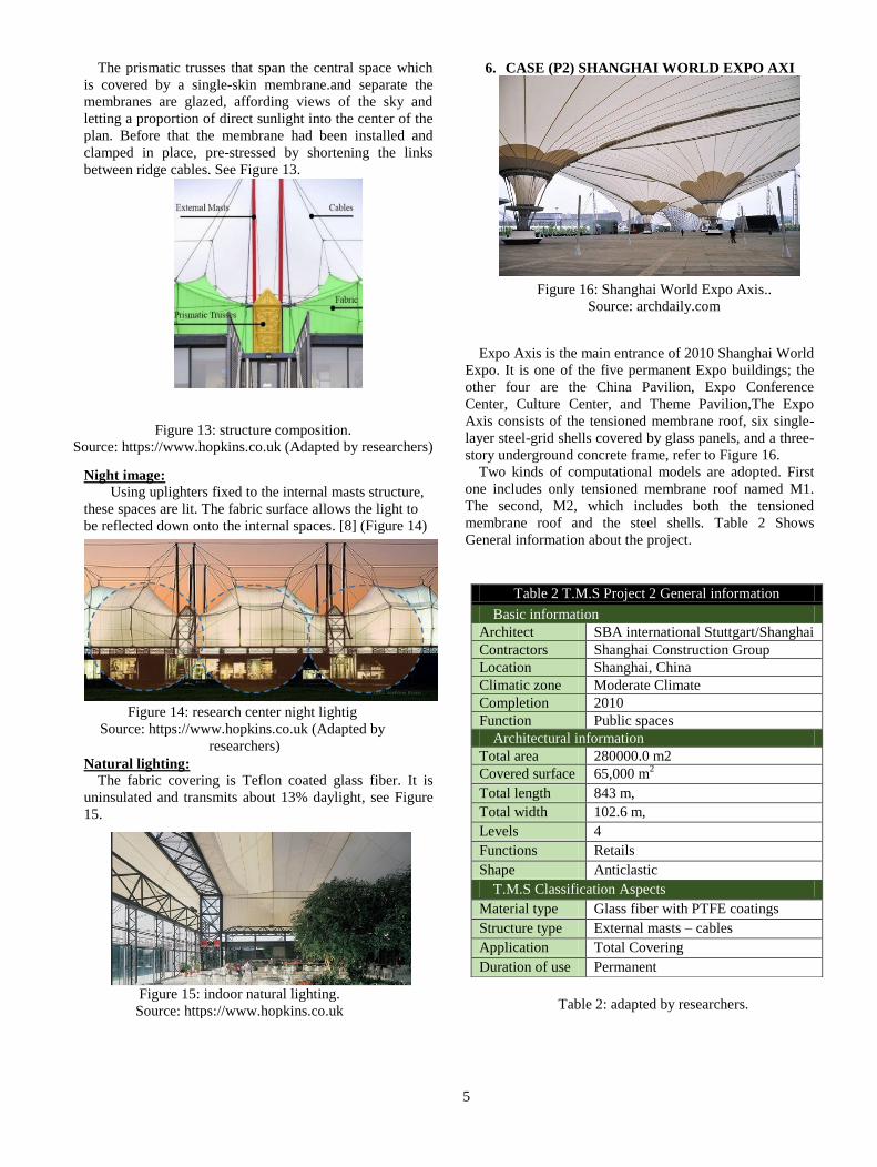
6. CASE (P2) SHANGHAI WORLD EXPO AXI
Expo Axis is the main entrance of 2010 Shanghai World
Expo. It is one of the five permanent Expo buildings; the
other four are the China Pavilion, Expo Conference
Center, Culture Center, and Theme Pavilion,The Expo
Axis consists of the tensioned membrane roof, six single-
layer steel-grid shells covered by glass panels, and a three-
story underground concrete frame, refer to Figure 16.
Two kinds of computational models are adopted. First
one includes only tensioned membrane roof named M1.
The second, M2, which includes both the tensioned
membrane roof and the steel shells. Table 2 Shows
General information about the project.
Table 2 T.M.S Project 2 General information
Basic information
Architect SBA international Stuttgart/Shanghai
Contractors Shanghai Construction Group
Location Shanghai, China
Climatic zone Moderate Climate
Completion 2010
Function Public spaces
Architectural information
Total area 280000.0 m2
Covered surface 65,000 m2
Total length 843 m,
Total width 102.6 m,
Levels 4
Functions Retails
Shape Anticlastic
T.M.S Classification Aspects
Material type Glass fiber with PTFE coatings
Structure type External masts – cables
Application Total Covering
Duration of use Permanent
Figure 14: research center night lightig
Source: https://www.hopkins.co.uk (Adapted by
researchers)
Figure 15: indoor natural lighting.
Source: https://www.hopkins.co.uk
Figure 16: Shanghai World Expo Axis..
Source: archdaily.com
Figure 13: structure composition.
Source: https://www.hopkins.co.uk (Adapted by researchers)
Table 2: adapted by researchers.
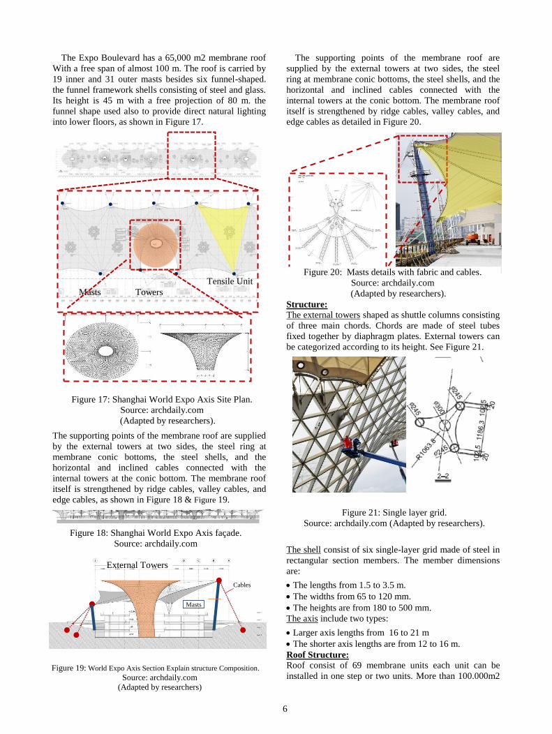
Figure 19: World Expo Axis Section Explain structure Composition.
Source: archdaily.com
(Adapted by researchers)
6
The Expo Boulevard has a 65,000 m2 membrane roof
With a free span of almost 100 m. The roof is carried by
19 inner and 31 outer masts besides six funnel-shaped.
the funnel framework shells consisting of steel and glass.
Its height is 45 m with a free projection of 80 m. the
funnel shape used also to provide direct natural lighting
into lower floors, as shown in Figure 17.
The supporting points of the membrane roof are supplied
by the external towers at two sides, the steel ring at
membrane conic bottoms, the steel shells, and the
horizontal and inclined cables connected with the
internal towers at the conic bottom. The membrane roof
itself is strengthened by ridge cables, valley cables, and
edge cables, as shown in Figure 18 & Figure 19.
The supporting points of the membrane roof are
supplied by the external towers at two sides, the steel
ring at membrane conic bottoms, the steel shells, and the
horizontal and inclined cables connected with the
internal towers at the conic bottom. The membrane roof
itself is strengthened by ridge cables, valley cables, and
edge cables as detailed in Figure 20.
Structure:
The external towers shaped as shuttle columns consisting
of three main chords. Chords are made of steel tubes
fixed together by diaphragm plates. External towers can
be categorized according to its height. See Figure 21.
The shell consist of six single-layer grid made of steel in
rectangular section members. The member dimensions
are:
The lengths from 1.5 to 3.5 m.
The widths from 65 to 120 mm.
The heights are from 180 to 500 mm.
The axis include two types:
Larger axis lengths from 16 to 21 m
The shorter axis lengths are from 12 to 16 m.
Roof Structure:
Roof consist of 69 membrane units each unit can be
installed in one step or two units. More than 100.000m2
Cables
Masts
External Towers
Figure 18: Shanghai World Expo Axis façade.
Source: archdaily.com
Masts Towers
Tensile Unit Figure 20: Masts details with fabric and cables.
Source: archdaily.com
(Adapted by researchers).
Figure 21: Single layer grid.
Source: archdaily.com (Adapted by researchers).
Figure 17: Shanghai World Expo Axis Site Plan.
Source: archdaily.com
(Adapted by researchers).

7
of PTFE fabrics were used for the tensile membrane
structure roof in order to cover Whole Boulevard which
summed an innovative and very special spectacular and
visual effect. Refer to Figure 22.
Factors Affecting Design Process Of T.M.S
Natural Lighting Internal spaces had its high quality of natural lighting,
this because of the mixture between direct and diffused
sunlight.it would be hard to achieve such a result using
another type of conventional roof. [9] See Figure 23.
Night image At night these spaces are lit by colored uplighters, fixed
to the internal Masts at the upper chord steel structure,
using the surface of the membrane to reflect light down
onto the spaces below. See Figure 24.
7. CASE STUDY (P3) KHAN SHATYR
ENTERTAINMENT CENTRE
This giant circus is a shopping mall and entertainment
centre, looked as tent structure, Designed by Norman
Foster. Its quilted fabric roof is controlling the interior
temperature to enjoy the artificial beach, with sand
imported from the Maldives. A The Khan Shatyr
Entertainment Centre is designed to provide the city with
a range of civic, cultural and social amenities all
sheltered within a climatic envelope - 'a world within' -
that offers a comfortable microclimate all year round,
whatever the weather. See Figure 25 and Figure 26.
Table 3 shows general information about the project.
Table3 T.M.S Project 3 general information
Basic information
Architect Norman foster architects
Client Sembol Construction
Location Astana, Kazakhstan
Climatic zone Cold, snowy climate
Completion 2010
Cost 150
Function Entertainment center
Architectural information
Total area 100,000m²
Covered
surface
30000 m2
Total length 200 m
Total width 150 m
Levels 6
Functions urban- park, 450m meter jogging
track shopping and leisure
facilities, restaurants, cinemas,
entertainment spaces, undulating
terraces, a water park, wave pools
Shape Cone
T.M.S Classification Aspects
Material type Ethylene Tetra Fluoro Ethylene
Structure type 150 m mast and cable net
Application Total Covering
Duration of
use
Permanent
Figure 22: Expo Structure Main Chords.
Source: Source: archdaily.com
(Adapted by researchers).
Figure 23: Natural lighting at the central spaces.
Source: archdaily.com
(Adapted by researchers).
Figure 24: Expo differnt night image.
Source: archdaily.com
(Adapted by researchers).
Figure 25: Khan Shatyr Entertainment Centre Astana,
Kazakhstan.
Source:fosterandpartners.com
Table 3: adapted by researchers.
8
Material cladding
the tent covered with a three-layers of ETFE, formed
as 3.5 x 30 m-cushions - a very light, economical and
thermally efficient solution. The building open areas are
tempered, with target temperatures of +14 C in winter
and +29 C in summer. Besides, the used cladding is
allowing light to flood large spaces and protecting the
interiors of the structures from powerful sunlight, wind
and snowfall. See Figure 27.
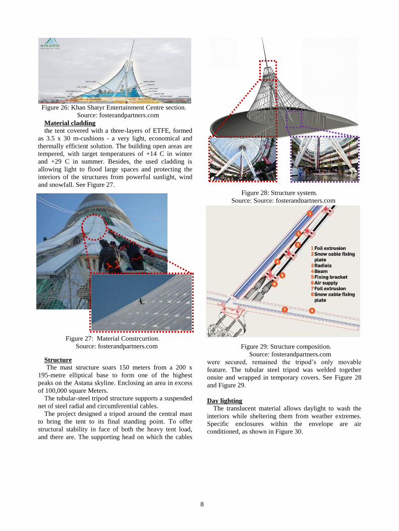
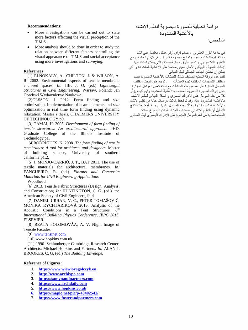
Structure
The mast structure soars 150 meters from a 200 x
195-metre elliptical base to form one of the highest
peaks on the Astana skyline. Enclosing an area in excess
of 100,000 square Meters.
The tubular-steel tripod structure supports a suspended
net of steel radial and circumferential cables.
The project designed a tripod around the central mast
to bring the tent to its final standing point. To offer
structural stability in face of both the heavy tent load,
and there are. The supporting head on which the cables
were secured, remained the tripod’s only movable
feature. The tubular steel tripod was welded together
onsite and wrapped in temporary covers. See Figure 28
and Figure 29.
Day lighting The translucent material allows daylight to wash the
interiors while sheltering them from weather extremes.
Specific enclosures within the envelope are air
conditioned, as shown in Figure 30.
Figure 26: Khan Shatyr Entertainment Centre section.
Source: fosterandpartners.com
Figure 27: Material Constrcurtion.
Source: fosterandpartners.com
Figure 29: Structure composition.
Source: fosterandpartners.com
Figure 28: Structure system.
Source: Source: fosterandpartners.com

9
Night image The building has a unique lighting system to control
the outer appearance of the building in different colors,
see Figure 31.
After analyzing all three case studies in the previous section, a comparative analysis will be held between them.
This is to observe the areas of strengths and those of weakness in the case studies, refer to table 4. Thus, this will
provide us with the necessary information and conclusions of the analytical part, to determine which factors are the
most influencing ones over the visual image and perception of TMS.
Table 4 : Comparative analysis between the three projects
According to Classification According to Factors Affecting
Structure Cladding
material
Natural lighting Night image
P1
External masts
– cables
Poly Tetra Flour
Ethylene - PTFE
Transmits only about 13%
daylight but it’s clearly
enough for the indoor
function
Using uplighters by fixing them to
the internal masts structure, these
spaces are lit. The fabric surface
allows the light to be reflected down
onto the internal spaces
P2
Internal and
External masts
– cables
Glass fiber with
PTFE coatings
PTFE material allows
daylight partially to lit up
the interior spaces
Uplighters fixed to the external masts
, led lights fixed to the masts
P3
Internal masts
and cable net
Triple layer of
ETFE
formed as 3.5 x
30-metre cushions
The translucent material
allows daylight to wash the
interiors while sheltering
them from weather extremes
The building has a unique lighting
system to control the outer
appearance of the building in
different colors.
Co
ncl
usi
on
Different
types of
Structure
elements highly
affects the
perception of
the entire shape
PTFE Materials
are more reliable
to use in order to
have more
attractive visual
perception from
the outside
ETFE is More translucent
than any other materials
used helping more natural
light to penetrate the indoor
space
For the different types of structure
elements or cladding material ,
external light units are needed to be
fixed or directed to the skin in order
to have a unique visual image for the
whole T.M.S
8. Conclusion:
After comparing three of the important T.M.S
projects in Europe / Asia with common structure
elements and different types of cladding materials the
following points were concluded:
Tensile Membrane Structures have a very
different visual image which allows designers,
architects or engineers to get a unique experience
forming and shaping exciting solutions to regular
design challenges.
Structure elements and cladding material are the
dominant factors affecting the whole visual image
for the T.M.S projects.
Steel Masts (Interior-Exterior) are the most
interesting Types of Structures we could use to
enhance the perception of the visual image as it's
clearly seen from inside or far away from outside
the building depending on its height
As for the cladding materials we can conclude that
different membrane materials (cushions or
fabrics) would give the designer more flexibility
to change the visual perception due to the amount
of translucency of the skin letting the light
through in or out the building.
Figure 31: different images at night.
Source: fosterandpartners.com
Figure 30: natural lighting in inner spaces.
Source: fosterandpartners.com
Table 4: Adapted by researchers.
10
Recommendations:
More investigations can be carried out to state
more factors affecting the visual perception of the
T.M.S
More analysis should be done in order to study the
relation between different factors controlling the
visual appearance of T.M.S and social acceptance
using more investigations and surveying.
References
[1] ELNOKALY, A., CHILTON, J. & WILSON, A.
R. 2002. Environmental aspects of tensile membrane
enclosed spaces. In: IIB, J. O. (ed.) Lightweight
Structures in Civil Engineering. Warsaw, Poland: Jan
Obrębski Wydawnictwo Naukowe.
[2]OLSSON, J. 2012. Form finding and size
optimization, Implementation of beam elements and size
optimization in real time form finding using dynamic
relaxation. Master’s thesis, CHALMERS UNIVERSITY
OF TECHNOLOGY.p9.
[3] TAMAI, H. 2005. Development of form finding of
tensile structures: An architectural approach. PHD,
Graduate College of the Illinois Institute of
Technology.p1.
[4]RODRIGUES, K. 2008. The form finding of tensile
membranes: A tool for architects and designers. Master
of building science, University of southern
california.p1:2.
[5] J. MONJO-CARRIÓ, J. T., BAT 2011. The use of
textile materials for architectural membranes. In:
FANGUEIRO, R. (ed.) Fibrous and Composite
Materials for Civil Engineering Applications
Woodhead
[6] 2013. Tensile Fabric Structures (Design, Analysis,
and Construction) In: HUNTINGTON, C. G. (ed.). the
American Society of Civil Engineers, ibid.
[7] DANIEL URBÁN, V. C., PETER TOMAŠOVIČ,
MONIKA RYCHTÁRIKOVÁ 2015. Analysis of the
Acoustic Conditions in a Tent Structures. 6th
International Building Physics Conference, IBPC 2015.
ELSEVIER.
[8] BEATA POLOMOVÁA, A. V. Night Image of
Tensile Facades.
[9] www.tensinet.com
[10] www.hopkins.com.uk
[11] 1990. Schlumberger Cambridge Research Center:
Architects: Michael Hopkins and Partners. In: ALAN J.
BROOKES, C. G. (ed.) The Building Envelope.
Reference of Figures:
1. https://www.wiewioragolczyk.en
2. http://www.archixpo.com
3. https://samynandpartners.com
4. https://www.archdaily.com
5. https://www.hopkins.co.uk
6. https://mapio.net/pic/p-40402541/
7. https://www.fosterandpartners.com
دساست ححللت للظسة البظشت لظبم الإشبء
ببلأغشت الوشذدة
:الولخض
ن فشاي أح بكل هؼخوذة ػلى الشذ ت القشى الؼششيف بذا ، طو
ف الأبم الحبلت، هغ . ببسخخذام فقبػبث طببى وبرس هؼوبست كبشة
الخطس الخكلص حافش طشق حسببت هؼقذة الخ وكي اسخخذاهب
لخ لإشبء الورس الكل الأهزل للوب هؼخوذا ػلى الأغشت الوشذدة ا
.وكي أى ححسي الضبب الضوبل لز الوبب
حقذم ز السقت البحزت حظف شبهل للوشآث ببلأغشت الوشذدة ضن
رن ؼشع البحذ هخخلف . هخخلف الخقسوبث الوخخلفت لز الوشآث
الؼاهل الوئزشة ػلى حظون ز الوشآث هغ إسخخلاص الؼاهل الوؤرشة
البظشت للوشآث ببلأغشت الوشذدة فن كف ؤرش ػلى إدساك الظسة
كل هي ز الؼاهل ػلى الإدساك البظشي الشكل البئ لظبم الإشبء
زا، قذ حن ححلل رلاد دساسبث حبلت هي ظبم الإشبء . ببلأغشت الوشذدة
لقذ أضحج خبئش . ببلأغشت الوشذدة لذساست حؤرشز الؼاهل ػلب
الخحلل أى الظبم الإشبئ الوسخخذم للغشبء الوشذد ع الوبدة
.ػلى الإدساك البظشي لز الوببالوسخخذهت ب هي أن الؼاهل الوؤرشة