Embed Size (px)
Citation preview

JAERI-Tech2001-044
JP0150728 *^-?K>•?".•<••*•
paam
ANALYTICAL STUDY OF NARROW CHANNEL FLOWFOR A SPALLATION TARGET SYSTEM DESIGN
July 2001
Md. Shafiqul Islam? Atsuhiko TERADA, Hidetaka KINOSHITA,Ryutaro HINO and Masanori MONDE*
Japan Atomic Energy Research Institute

(T319-1195
319-1195
This report is issued irregularly.Inquiries about availability of the reports should be addressed to Research
Information Division, Department of Intellectual Resources, Japan Atomic EnergyResearch Institute, Tokai-mura, Naka-gun, Ibaraki-ken 319-1195, Japan.
© Japan Atomic Energy Research Institute, 2001

PLEASE BE AWARE THATALL OF THE MISSING PAGES IN THIS DOCUMENT
WERE ORIGINALLY BLANK
JAERI-Tech 2001-044
Analytical Study of Narrow Channel Flowfor a Spallation Target System Design
Md. Shafiqul Islam* Atsuhiko TERADA*, Hidetaka KINOSHITA,
Ryutaro HINO and Masanori MONDE*
Center for Neutron Science
Tokai Research Establishment
Japan Atomic Energy Research Institute
Tokai-mura, Naka-gun, Ibaraki-ken
(Received May 8, 2001)
Heat transfer and pressure drop characteristics under fully developed turbulent water
flow condition were analyzed over a two-dimensional narrow rectangular channel
whose height is H=1.2 mm. The channel configuration and water flow condition
simulate forced convection cooling of a spallation target system components design
such as a solid target and a proton beam window. The high-Reynolds number form of
the standard k-e and RNG&-e models employing wall functions for the Reynolds
number (Re) range of 7,000 to 22,000 were used in the analyses. As for heat transfer
characteristics of a smooth channel, the Nusselt number obtained by the standard k-e
model agreed very well with the Dittus-Boelter correlation. No significant differences in
friction factors for the smooth channel were observed for these two models, which
agreed well with the Blasius correlation. However, the standard k-e model could not
predict friction factors well for the rib-roughened channel.
Keywords: Pressure Drop, Turbulent Flow Heat Transfer, Narrow Channel,
Two-dimensional Analysis, Forced Convection, Spallation Target System,
Turbulent Model, Wall Functions.
>& On leave from Ishikawajima-Harima Heavy Industries Co., Ltd.
* Saga University

JAERI-Tech 2001-044
Md. Shafiqul Islam* • 3fffl & PI Hi JSCI'J*
( 2 0 0
1.2mm
L T l / i ' 7 ;i/XS(Re) ^ 7,00022,000
Dittus-Boelter
: T319-H95

JAERI-Tech 2001-044
Contents
1. Introduction 1
2. High Heat Flux Components in a Spallation Target System 2
3. Literature Survey 5
4. Turbulent Model Performance in Narrow Channel Flows 8
4.1 Description of Problems 8
4.2 Governing Equation 11
4.3 Major Feature of Turbulent Model 13
4.4 Boundary Conditions 13
4.5 Numerical Procedures 15
5. Computational Results and Discussion 16
5.1 Frictional Pressure Drop Performance 16
5.2 Heat Transfer Performance 18
6. Concluding Remarks 20
Acknowledgements 21
References 23

JAERI-Tech 2001-044
l.
2.
3. '
4.
4.1
4.2
4.3
4.4
4.5
5. m^5.1
5.2 m
6. I
m
1
2
5
8
8
n13
13
15
16
16
is
20
21
23

JAERI-Tech 2001-044
1. Introduction
The Japan Atomic Energy Research Institute (JAERI) and the High Energy Accelerator
Research Organization (KEK) are jointly developing a next generation neutron source
using a high-intensity proton accelerator in order to use high-intensity neutrons in the
fundamental sciences and nuclear engineering fields. The proposed spallation neutron
source will use a proton beam power up to as high as 5 MW. Development of a
MW-class spallation neutron source is one of the most difficult technical challenges. Two
types of targets, namely, a mercury target and a solid target which work as spallation
neutron sources have been proposed . According to the conceptual spallation mercury
target system design f2J, it consists of a target vessel and a safety hull. A 1 MW pulsed
proton beam from the high-intensity proton accelerator will be injected into the mercury
target to produce high-intensity neutrons. With the spallation reaction of the injected
proton beam and mercury nucleus, huge amount of heat will be generated and deposited
in mercury. For the safety design of the MW-class mercury target system, sufficient heat
removal with a slow mercury flow is necessary to prevent corrosion and erosion of the
target vessel. According to the conceptual solid target system design [1], the solid target
consists of heavy metal target plates made of tungsten, and it could be used under a
proton beam power up to 2.5 MW. Through the spallation reaction between the pulsed
proton beam with 1 ji s pulse length up to 50 Hz and the tungsten nucleus, huge amount
of heat will be generated and deposited in the target plates. Thus, it is necessary to
remove this huge amount of heat generation efficiently in order to maintain structural
integrity.
Another important technical aspect in the spallation neutron source facility is to design
the proton beam window , which acts as a boundary between a proton beam line
(vacuum) and the target system (helium atmosphere). The proton beam window consists
of two Inconel plates and located at the end of the proton beam line. There will be a high
heat deposition in these plates, and it is necessary to cool down the plates so as to avoid
excessive thermal stress. Cooling channels in the solid spallation target and the proton
beam window are very narrow in order to minimize water volume, which affects the
neutron yield. In order to remove huge amount of heat generation from the spallation
target system components, heat transfer enhancement technique using
repeated-micro-ribs working as turbulent promoters in a narrow water-flow channel has
been proposed. Smooth narrow channel will cause not only high coolant velocity but also
flow-induced vibration, erosion and flow disruption. A brief description of spallation
- 1 -

JAERI-Tech 2001-044
target system components are described in Chap. 2. The main objective in this study is to
make clear heat transfer and pressure drop characteristics under turbulent flow condition
in a narrow channel for a spallation target system components design by numerical
analyses.
2. High Heat Flux Components in a Spallation Target System
In the conceptual spallation mercury target system design, an integrated structure of
target vessel with the safety hull was proposed to ensure the safety and to collect mercury
in case of mercury leakage caused by the target beam window failure. The inner structure
arrangement of the mercury target vessel was determined based on thermal-hydraulic
analytical results of 3 GeV, 1 MW proton beam injection. The mercury target currently
under conceptual design adopted a cross-flow type (CFT) target vessel. Figure 1 shows
the cutaway view of CFT mercury target with the safety hull. Mercury enters into the
target from the furthest side from the beam window and flows along the blade flow
distributor in the inlet plenum toward each end of the blade, and then crosses over the
proton beam and returns through the outlet plenum along the blades. The target vessel
will be made of 316-stainless steel and its size presently under design is 260 mm in width,
80 mm in height in front of the target and 800 mm in effective length. In order to ensure
safety of the target system, the integrated structure of target vessel with the safety hull
was proposed as shown in Fig. 2. The vessels for mercury target, helium and heavy water
will be connected each other by reinforcement ribs mounted on the surface of each vessel
by welding. The safety hull consists of helium and heavy water vessels, which is known
as outer vessel. Narrow heavy water-flow channel by introducing repeated-micro-ribs
inside will be used to remove excessive heat of outer vessel's beam window.
In the conceptual spallation solid target system design, the solid target consists of
tungsten target plates and it could be used against a proton beam power up to 2.5 MW.
There will be 39 target plates of which thickness varied from 6-25 mm with dimensions
of 170 mm in length and 70 mm in height. They will be arranged in a row against
injected high-intensity proton beam power up to 2.5 MW. Figure 3 shows the concept of
the solid target. Heavy water will be used as a coolant to minimize the neutron capture
and it flows horizontally to cool down the target plates. Heavy water will also be used to
cool down the outer vessel of the target container under the 2.5 MW proton beam
operation. Figure 4 shows the power density calculation result of the solid targets
assuming uniform proton beam profile. According to Fig. 4, the maximum heat flux is
- 2 -

JAERI-Tech 2001-044
calculated to be 1.28 MW/m2 under 2.5 MW operation. Through the spallation reaction
between the proton beam and the target nucleus, high-density heat up to 1.2 kW/cm3 will
be generated in the target plates. The maximum heat flux reaches 3.6 MW/m2 even in
thin target plate, which has a thickness of 6 mm. The cooling channels between the plates
are very narrow in order to decrease water volume ratio affecting the neutron yield. In the
current solid target design, the gap of water-flow channel is 1.2 mm and water volume
ratio to the target metal volume is being kept to less than 10 %. Repeated-micro-ribs on
one side of the target plates are adopted in order to remove this high heat flux efficiently.
Another important aspect of high heat flux component of a spallation target system is
the proton beam window that locates at the end of proton beam line and acts as a pressure
boundary between vacuum and helium atmosphere. It consists of two Inconel plates,
which are cooled down by heavy water flowing vertically from the bottom to the top of
the plates. In the current proton beam window design, the gap of a water-flow channel is
5 mm. Figure 5 shows the concept of a flat-type proton beam window to be applied to a
5 MW proton beam operation. The dimension of a proton beam window is 330 mm in
width, 235 mm in height and 65 mm in depth. Light water flowing from two inlet pipes is
adjusted by using flow guides in order to distribute its flow rate uniformly in the window
section. The maximum volumetric heat deposition at the window will be 960 W/cm3
under 5 MW operation. The thickness of the window will be less than 3 mm.
Repeated-micro-ribs will also be formed on one side of the plates.
To design the cooling channel between the target plates and the proton beam window,
heat transfer enhancement using repeated-micro- ribs working as turbulent promoters in a
narrow channel has been proposed so as to remove high heat flux to keep the temperature
of the target plates and mercury target vessel sufficiently low with relatively low coolant
velocity. It is difficult to comprehend the heat transfer mechanism in the turbulent flow
regime due to eddy, separation, and reattachment. Even though these difficulties, it is
necessary to make clear the heat transfer and pressure loss characteristics in a
rib-roughened narrow channel both analytically and experimentally in order to
understand the mechanism of heat transfer enhancement better and to design the target
system components.
Many studies on heat transfer enhancement using repeated ribs have been carried out
both analytically and experimentally on tubes and annuli under air-flow conditions but
very few studies are on narrow rectangular channels under water-flow condition. There
are virtually almost no heat transfer data available both analytically and experimentally
- 3 -

JAERI-Tech 2001-044
on a very narrow rectangular channel with repeated-micro-ribs under water-flow
condition. Islam et al. [4] investigated for the first time to measure the heat transfer and
pressure loss data experimentally [4] on such a narrow rectangular channel with
repeated-micro-ribs under water-flow condition. The data revealed that a high potential
heat transfer in the rib-roughened narrow channel but fluid flow and heat transfer
mechanisms are not yet made clear. In this study, in order to understand the complex
mechanism numerically, a CFD analytical tool, the Star-CD code, was selected.
Engineering practice is also necessary to use empirical roughness functions to describe
the near wall region, and analytical or numerical solution scheme to calculate the core
flow in the narrow smooth and rib-roughened channel.
The k - e model is presently the most widely used turbulent model for practical
analyses and has been built into virtually all-commercial general-purpose CFD codes.
Bridging the viscosity-affected near-wall layers with the wall functions, most
calculations carry out so far with the k-e model. The wall functions involving the
friction velocity are of course particularly unsuited for separation and reattachment
regions where the friction velocity changes significantly. In order to make the k - a
model applicable to the viscosity-affected near-wall region, the standard
high-Re-number version had to be modified by replacing some of its constants by
viscosity-dependent functions and additional terms in the k-e equations. This is the
"low-Re-number and two-layer models" approach that had been used for simulating the
turbulent processes very near walls.
The cross-sectional geometries of a flow channel with and without repeated-micro-
ribs surfaces of this study are shown in Figs. 6 and 7, respectively. Their dimensions are
also figured out. Each of channels consists of a space enclosed by solid walls with an
inlet and an outlet. The fluid within the geometry is water and its thermo-physical
properties are evaluated at 15°C. The total mass entering the channel exits through the
outlet. The flow is assumed to be two-dimensional turbulent flow with constant fluid
temperature, density and viscosity. The high-Re-number form of the standard k-e and
RNG k-e turbulent models were used in the analyses. The analyses were performed
for the non-heating and heating with uniform wall heat flux from one-side, for a range of
the Reynolds numbers from 7,000 to 22,000. The various investigations carried out on
rib-roughened surfaces both experimentally and analytically to date have been presented
in Chap. 3.
- 4 -

JAERI-Tech 2001-044
3. Literature survey
Improvements of heat transfer performance through passive and active enhancement
methods have been studied intensively for over 30 years. Heat exchangers with
single-phase tube-side flow are one of the important applications where passive
surface-modification methods are popularly applied. Typical examples of passive heat
transfer enhancement techniques are:
(i) Surface roughness
(ii) Displaced turbulent promoters, and
(iii) Swirl flow generators.
Surface roughness is one of the promising techniques to be considered seriously as a
means of enhancing forced-convection with single-phase flow heat transfer. Initially it
was speculated that elevated heat transfer coefficients might accompany the relatively
high friction factors of rough conduits. However, since the commercial roughness is not
well defined, artificial surface roughness-introduced through knurling or threading or
formed by repeated-rib turbulent promoters has been employed. Although the enhanced
heat transfer with turbulent promoters is often due to the fin effect, it is difficult to
separate the fin contribution. In certain cases it may be desirable to leave the heat transfer
surface intact and achieve the enhancement by disturbing the flow near the heated
surface. Displaced turbulent promoters alter flow mechanics near the surface by
disturbing the core flow and can be done by placing thin rings or discs in a tube. It is
seen that the rings substantially improve heat transfer in the lower Reynolds number
range where the discs are not particularly effective. Examples are baffles and mixing
elements. It has been established that the swirling flow will improve heat transfer in a
duct flow. Generating of swirl flow has been accomplished by coil wires, spiral fins,
stationary propellers, coiled tubes, inlet vortex generators, and twisted tapes. All of these
heat transfer enhancement methods improve single-phase and boiling heat transfer at the
expense of increased pumping power. Heat transfer coefficients are relatively high for
vortex flow due to an increase in velocity and a secondary flow produced by the radial
body force when a favorable density gradient is present and a fin effect with certain
continuous swirl generators.
With the passage of time, the above types of surface roughness are being utilized more
and more for enhancement of heat transfer. Active enhancement, which has also been
studied extensively, requires the additional of external power to achieve the desired flow
modification. They include heat transfer surface vibration, fluid vibration, and
5

JAERI-Tech 2001-044
electrostatic field introduction, are costly and complex. Of the several methods discussed
above, the most popular and successful technique is the enhancement through surface
roughness. This is mainly because of its effectiveness in enhancing the heat transfer,
relatively easy to manufacture, less cost and simplicity in application. Ribs, indentations,
spiral flutes and coil inserts are some common surface modification (roughness)
techniques that are currently used or have been proposed for single-phase heat transfer
applications. Of these, two-dimensional transverse type repeated-rib promoter is unique
because of the two-dimensional flow field and the design control parameters are just the
rib height (k), rib spacing (p) and the rib shape. As for spirally indented, fluted and
ribbed tubes, the flow field becomes three-dimensional where a helix angle becomes an
additional and essential design parameter.
Such rib-roughened tubes are sometimes considered in the design of shell-and-tube
heat exchangers. For examples, they applied include single-phase tube of flooded chillers
for air conditioners, surface of condensers for power plants. The size of these heat
exchangers can be reduced considerably by use of rib-roughened tubes instead of smooth
tubes. This has important potential applications of large systems such as those used in
thermal, geothermal, and ocean thermal energy conversion (OTEC) power plants, which
require very large heat exchangers. In addition to these applications, narrow channel with
repeated-rib type promoters is now considered to be applied for the high heat flux
spallation target components. In spite of increasing the use of these rib-roughened tubes
or channels, there are no general correlations available for quantitative evaluation of
pressure drop and heat transfer. In one of the early studies on ribbed tubes, Kalinin et al.[5] proposed correlations for pressure drop and heat transfer. However, the correlations
are valid only for transverse ribs within the specific ranges of k/De=0.016-to-0.07 and
p/De=0.25-to-1.0, respectively.
Many of the studies found in the literature have tried to extend the studies of
Nikuradse [61 on friction with sand-grain roughness and the heat
transfer-momentum-transfer analogy of Dipprey and Sabersky [7] for this type of
roughness, while Gee and Webb I81 proposed correlations for helical ribs, without
including the effects of the pitch. The most general correlations to date were proposed by
Withers[9], Li et al.1101, and Nakayama et al.1"1 for helically ribbed tubes. Han et al.[121
systematically investigated the effects of the rib pitch-to-height ratio (p/k), the
height-to-equivalent diameter ratio (k/De) and the effect of helix angle ( a a) on the heat
transfer coefficient and the friction factor of fully developed turbulent air flow in ducts
6 -

JAERI-Tech 2001-044
that had two or four opposite rib-roughened walls. Liou et al.[131 also presented the
simplest correlations to see the effects of rib shapes on turbulent heat transfer and friction
in a rectangular channel. The Webb et al.[14] correlations are applicable to water, air and
n-butyle alcohol for transverse repeated-rib roughness in a tube.
A comprehensive list was prepared consisting of all the experimental investigations
from which heat transfer and friction factor data could be extracted for different
roughened surfaces for single-phase turbulent flow in internally roughened tubes up to
now. No restrictions were placed on the flow parameters, namely, the Reynolds number
and the Prandtl number, even though much of the data were obtained in the turbulent
regime with either air or water as the test fluid. This file lists the authors of the
investigation and the type of enhanced tubes along with number of tubes tested in the
experiments, which are summarized in Table 1. The sources are listed in the reference
section. In addition, the type of experiment, whether the fluid is heated or cooled, and the
method of heat transfer are provided whenever possible for future reference.
In addition to numerous experimental studies cited above, a number of numerical
studies have also been performed in order to predict the flow behavior in near-wall
region and flows past two-dimensional ribs. Typical numerical studies with the linear
k-e model (Launder and Spalding, [43]) are: Lewis [44], Lee et al.[45], Patankar et al.[46]
Liou et al.[47], Durst and Rastogi [48], Yap [491, Jones and Launder [501, Benodekar et al.[52],
Chung et al.[53], Park and Chung [54], and Leschziner and Rodi1511.
The first attempt to analytical determination of the roughness functions for flow over
rectangular ribs was made by Lewis [44]. The flow was approximated by a series of
attached and separated flow regions, and some empirical information from experiments
over cavities and steps was required. The k - E turbulent model with wall function
boundary conditions was used by Lee et al.[45] to predict roughness functions in an
annulus with a ring type rectangular roughness on the inner pipe. In a numerical study,
a fully developed flow in a single module was solved using the periodicity conditions, as
proposed by Patankar et al.[461 in order to avoid the entrance region effect. Liou et al.l4?1
made numerical computations for turbulent flow over a single rib-roughness in a channel.
Numerical calculations for flow over two-rib roughness in a channel were performed by
Durst et al.[48].
Recently Yap has made a numerical study using various turbulent models. The best
heat transfer prediction was obtained with a low-Re-number k - E turbulent model
- 7 -

JAERI-Tech 2001-044
across the viscous sublayer and an algebraic stress model in the core flow. However, the
Jones and Launder version ' of the low-Re-number k - e model employed for the
whole flow regime gave fairly good predictions, provided an appropriate source term was
added to the transport equation for the turbulent dissipation rate. Yap[491 also found that
the wall function approach showed poor Reynolds number dependence for the peak
Nusselt Number, even with the algebraic stress model employed in core. Leschziner and
Rodi [5I] derived the standard k-e turbulent model with and without the curvature
correction equation to solve for the turbulent flow field and heat transfer between
successive ribs in the periodic fully developed regime of a ribbed annulus. Applying this
correction of the k-e model to the analyses of annular and twin parallel jets, they
obtained greatly improved predictions compared with the standard k-e model.
Durst and Rastogi l48J' Benodekar et al.[S2], Chung et al.[53], and Park and Chung [54]
have also carried out comparisons between k-e model results with and without
curvature corrections, and experimental results. Standard wall functions were used in all
these numerical studies. Use of wall functions as boundary conditions when solving
turbulent flows using the k-e model has been relatively successful where properties
are constant. But for large and irregular property variations in the viscous sublayer and
buffer layers, the use of wall functions presents a fundamental problem. Large and
irregular property variations of water at high temperature would complicate the
development of reference property schemes as a reference property scheme can be used
in the wall functions. Since many investigations have been carried out both
experimentally and analytically on tubes and annuli under air-flow conditions but very
few studies are on narrow rectangular water-flow channel. There are almost no heat
transfer data available both experimental and analytical on a very narrow rectangular
channel with one-side repeated-ribs and one-side constant heat flux under water-flow
condition. The objective of this literature survey is to make clear that thermal-hydraulic
studies by experimentally and analytically on such a narrow channel would be the first
step to date.
4. Turbulent model performance in narrow channel flows
4.1 Description of problems
Problems to be considered in this study are depicted schematically in Figs. 8 and 9,
respectively. Each of them involves the determination of two-dimensional heat transfer
and fluid flow characteristics for turbulent forced-convection cooling. The computational

JAERI-Tech 2001-044
geometry of smooth and rib-roughened narrow rectangular channels consist of a space
enclosed by solid walls with an inlet and an outlet and its major controlling parameters
are shown below. A uniform heat flux is supplied fiom the bottom side and the opposite
side is insulated so as to remain adiabatic condition. The fluid within the geometry is
water and its thermo-physical properties at 15°C are as follows:
(i) Density, p = 997.09 kg /m3
(ii) Molecular viscosity, l± = 890.72 X 10"6 Pa s
(iii) Specific heat, Cp = 4180.0 J / (kg K)
(iv) Thermal conductivity, A = 0.604 W/(m K)
(v) Molecular Prandtl number, Pr = 8.06
The total mass entering the geometry exits through the outlet. The flow is assumed to be
two-dimensional turbulent one with constant fluid temperature, density and viscosity.
(1) Modeling Strategy
The following modeling strategy is used:
(i) Cartesian coordinate system with uniformly spaced hexahedral cells
(ii) Inlet, outlet, wall and symmetry plane boundary conditions.
(iii) Incompressible and steady flow options.
(iv) Appropriate physical parameters for water
(v) k - e turbulent models for the turbulent characteristics
(2) Analytical Procedure
In each model, the channel height (H) was fixed for 1.2 mm, an entrance and an exit
lengths for 0 -25 mm and a heating length for 200 mm as a reference that was assumed
in the conceptual design of the solid target[1].
Entrance Developed zone Exitregion (heating zone) region
H = 1.2 mm
0 - 25 mm 200 mm 0-25 mm
Equivalent hydraulic diameter, De = 4(W X H) / 2(W+H)
= 2H, i f W » H
= 2.4 mm, where channel height, H = 1.2 mm
- 9 -

JAERI-Tech 2001-044
(3) Solution flow chart
The procedural steps how to obtain simulated friction and heat transfer data from the
input values are given in a flow chart as shown below: At first, input values of flow
velocity (u), channel height (H), and y+ values, grid size of the computational geometry
were fixed. After fixing grid size, fluid properties, boundary conditions and solution
parameters were given as the input data of a analysis CFD-code, Star-CD. After running
the STAR-CD interactively, local parameters such as, surface, bulk temperatures, and
pressure drop data were obtained. From pressure drop, friction data were evaluated and
then compared with the reference-Blasius one. Similarly, from local surface and bulk
temperature data, local heat transfer coefficient consequently local Nusselt number were
evaluated and then compared with the reference-Dittus-Boelter (D-B) one.
Input values
>
Grid size
Star-—\
Temp
distribution etc
f
Tb, Tw etc
>f
h
t
11 U simulation
y + •* f S/R
>
Pressure
distribution etc
APetc
>f
I Simulation
1
N U D - B
• 1 0 -

JAERI-Tech 2001-044
4.2 Governing equation
The three-dimensional Reynolds Averaged Navier-Strokes and energy equations along
with the eddy viscosity concept are solved by the Star-CD to describe the incompressible
flows in the computational domain. These equations are written in a Cartesian tensor
form as shown below;
(1) Continuity equation
3ul
dxi
(2) Momentum equation
6ui dui SP 6 .dui Suj STIJp r p U j — r fx ^ -r ) T \^)
Where j = x, y, z and i = x, y, z
(3) Energy equation
P^7"= —L(«+«f)— J (3)
Where turbulent dynamic thermal diffusivity at are given by
"•• I f <4)
The models chosen were the high-Re-number form of the Standard k-e and RNG
k - e . Constant thermo-physical properties were assumed, and natural convection is
excluded as (Gr/Re2) < 0.0002 where Gr and Re are the Grashof and the Reynolds
numbers respectively.
(4) Standard k-e high-Re-number model equations
The turbulent kinetic energy (k ) and its dissipation rate (e) are computed from the
standard k-e model of Launder and Spalding where the standard k-e model is
based on the Boussinesq approximation. The modeled transport equations for turbulent
kinetic energy (k ) and dissipation (e) are expressed for steady state, incompressible
- 1 1 -

JAERI-Tech 2001-044
flow, linear contribution, and negligible buoyancy effect as:
-)=HtP-pe (5)8xt 5k
~{pute -^f-^r) =Cel Ufi, P]-Ce2 p^- (6)ax: 5, ox, k k
li,=cfipk2le (7)
Where P denotes the production rate of kinetic energy, k , which is given by:
P = 2S ( 8 )
S.^L^L^) (9)
2 dXj dx;
And
Veff=V + H, (10)
(5) Standard RNG k-e high-Re-number model equations
The RNG (renormalization group) model is an alternative to the standard k-e
model for high-Re-number flows. The model, which derives from a renormalization
group analysis of the Navier-Stokes equations, differs from the standard model only
through a modification to the equation for £ , except for using a different set of model
constants. This model does not include compressibility or buoyancy effects.
A / - u £-!-*-*L) =C - \ P]-C g2 C,?73(l->7/?7o)pg2
<&,. ' 6C &ct nk k 1 + fir]3
where
v ) 0 5 - (12)
and r]0 and /3 are additional empirical model constants given in the Table 2.
The constants appearing in Eqs. (5), (6), and (11) take values in the Table 2, which are
- 1 2 -

JAERI-Tech 2001-044
taken from Launder et al.[43].
4.3 Major Feature of Turbulent Model
(1) Standard k-e high-Re-number turbulent model
(1) With use of wall functions
(ii) Not valid in the region within the layer where molecular and turbulence effects are of
comparable magnitude
(iii) Need not to employ a fine computational mesh within the layer
(2) Standard RNG& - e high-Re-number turbulent model
(i) Renormalization Group (RNG)
(ii) Improved version of the standard k-e turbulence model
(iii) With use of wall functions
(a) Wall functions
(i) Wall functions are well-known algebraic formulas, which represent the
distribution of velocity, temperature, turbulent kinetic energy and its dissipation rate
within the turbulent boundary layers that form adjacent to the wall,
(ii) They allow the boundary layer to be bridged by a single cell,
(iii) They are often used to bypass the necessity of detailed numerical treatment and
the uncertain validity of a turbulence model,
(iv) Wall functions are an economic way of representing the turbulent boundary
layers (hydrodynamic + thermal) in turbulent flow calculations,
(v) Wall functions to be effective, while the dimensionless normal distance,
y+ = y u*/ o from the wall must not be too small or too large. Generally, y+ range =
3 0 - 1 5 0 is used [551.
4.4 Boundary conditions
(1) Entrance
Hydro-dynamically developed uniform flow distribution and a uniform temperature To
are assumed at the inlet of the channel in the present study. The inlet velocity, turbulent
kinetic energy, k and its dissipation, e profiles are obtained from a calculation of
two-dimensional turbulent channel flow.
- 1 3 -

JAERI-Tech 2001-044
(2) Exit
At the outlet the stream wise gradients of all variables are set to be zero.
f = 0; f ={u,v,k,e,T} (13)
(3) Symmetry
At the symmetry planes, the normal velocity component and the normal derivatives of
all other variables are set to be zero:
^ = 0; f={u,v,k,e,T} (14)dz
(4) Wall Boundaries
The wall functions proposed by Launder and Spalding, which are a linear-law
relationship when yn+ < 11.6 and a log-law relationship when yn
+ > 11.6 are used to
prescribe the boundary conditions along the channel walls. The wall functions are
applied in terms of diffusive wall fluxes. For the wall-tangential moment, the wall-shear
stress is specified as:
ln(£y + )
Where the wall functions constant, E = 9.0, K =0.42 and the non-dimensional wall
distance y+ is defined as:
v vC / 4 k / 2
- ^ >— (16)
The subscript, p, refers to node-point of the first grid adjacent to the wall. The production
rate of k and the averaged dissipation rates over the near-wall cell for the k equation
as well as the value of e at the point p are computed respectively from following
equations:
- ^ (17)yP
- 1 4 -

JAERI-Tech 2001-044
3/ 3/y" C Mk / 2
(18)
3/
3/ * / 2
/' 4 " (19)
For the temperature boundary condition, the heat flux to the wall is derived from the
thermal wall function:
, . .W^'. (20)Pr,[-ln(£y*) + P]
K
Where the empirical P function is specified as:
Pr
No-slip conditions for the velocity and the wall conditions for the turbulence
quantities are specified at all of the boundary surfaces, including the rib surfaces.
4.5 Numerical Procedures
The Star-CD is a powerful CFD tool for thermo-fluids analysis, which has been used
by the authors in order to investigate the velocity and temperature fields in
two-dimensional turbulent channel flows with smooth and transverse repeated ribs. Its
computational algorithm employs the SIMPLE method proposed by Patankar and the
control volume approach is adopted to solve the hydrodynamic equations using a finite
difference scheme. The study examined the performance of three discretization schemes
(given below) for convection for the standard k-e and RNGA; - e model solutions:
1. Upwind differencing scheme (UD)(First order differencing scheme)
2. Self-filtered central differencing scheme(SFCD)(Second order differencing scheme)
3. Quadratic upstream interpolation of convection kinematics scheme (QUICK) (Third
order differencing scheme)
No distinguishable results were found among these. The convergence criterion used in
- 1 5 -

JAERI-Tech 2001-044
this computation is the value of mass flux residuals (mass flow). The under-relaxation
factors for the velocity, the pressure, the turbulent kinetic energy, and the energy
dissipation rate are set to be 0.7, 0.2, 0.7, and 0.95, respectively. The number of the
iterations quite depends on the Reynolds number, grid sizes, and geometric parameters.
5. Computational Results and Discussion
5.1 Frictional pressure drop performance
To see the effect of grid size on frictional pressure drop and heat transfer, analyses
were performed at different computational geometry's based on dimensionless distance
(y+) and the Reynolds number (Re). To account for the near-wall effects in the standard
k-e , RNGA:-e models, the wall functions were used. This required the first interior
grid point to be at a distance y+ > 11.5 from the wall and required modifying the diffusion
coefficient at the wall to satisfy the law of the wall relationship. To determine the grid
size of the computational geometry of a smooth channel, a boundary layer thickness
equation was used. The equation is given as:
(22)
In simplified form, we have the dimensionless distance,
y+ = 0.0993 Re ° 875 (y / H ), (23)
To verify the ability of the wall functions for the standard k - e , RNGk - e models,
three sets of y+ values have been taken as 45, 22 and 15, respectively. It must be
mentioned here that the Star-CD calculates half of the y+ value in the computation.
Generally y+ is the total dimensionless distance of each cell of a computational geometry.
However in Star-CD calculations, y+ lies at the center of each cell. Smooth surface
pressure drop and heat transfer were computed at channel height of 1.2 mm for the
Reynolds number range of 7,000 to 22,000. One of the computational grids along with
velocity magnitude of a smooth narrow channel for two-dimensional flow case is shown
in Fig. 10. In the channel, the flow is entering at the inlet port with a uniform velocity of
3.5 m/s where the Reynolds number is 7,000 and the turbulent parameters (k &e) are
specified. The walls, which are parallel to the flow axis (X) are symmetric planes. The
thermo-physical properties of water were taken at 15 C in the computation. The entire
- 1 6 -

JAERI-Tech 2001-044
computational flow length is 200 mm. Several computations of the standard k - e and
RNG A: - e models were performed with different mesh sizes, which are summarized in
the Table 3. From Table 3, it is seen that the mesh size depends on the Reynolds number
and dimensionless distance y+ values. The mesh size must be adjusted when the Reynolds
number was changed in order to keep a certain dimensionless distance y+ value.
Based on this computational domain, frictional pressure drops and heat transfer
performances were evaluated and compared with the reference one. The frictional
pressure drops and heat transfer were calculated in the fully developed flow region.
Figures 11 and 12 show the pressure loss distribution in each segment along the flow
channel. Each segment is at a distance of 5 mm. It is seen from these figures that fully
developed flow was began at 70 mm (L / De = 29) from inlet of the flow length. The
pressure drop was obtained within the fully developed flow regime of 60 mm (90 - 150)
mm from the analytical results obtained by the Star-CD. The local pressure loss data,
which were obtained by the standard k - e and RNG k-e models, are given in the
Table 4. There are fourteen cases enlisted in the Table 4. Every three cases along with the
last two cases is a particular Reynolds number where the mesh size is only the variable
parameter. The frictional pressure loss data, which were calculated by the Blasius
correlation, is also included for comparison. The calculated pressure drop quite depends
on the grid size of a geometry. The calculated pressure drop agrees well with the Blasius
prediction in the case of y+ = 22. The prediction of pressure drop is almost the same as to
y+ = 45 but quite high in the case of y+ = 15 (y+ < 11.5). Because the grid size of y+ = 15
was placed too close to the wall so that the ability of the wall functions was lost. The
calculated frictional pressure drop was evaluated by the following equation:
fsimulation= A P D e / ( 2 l W ) (24)
And the reference one was predicted by the Blasius equation:
f Blasius = 0.079 Re-0 2 5 (25)
Figure 13 shows frictional pressure drop with respect to the dimensionless distance y+
that was simulated by the Standard k-e and the RNG models under different Reynolds
number. It is shown from this figure that frictional pressure loss agrees well with the
reference one at y+= 26 (Star-CD, y+= 13) and both the standard k-e and the RNG
models would be suitable to predict pressure loss characteristics in a smooth narrow
channel geometry under water-flowing condition. Figure 14 shows the discrepancy of
- 1 7 -

JAERI-Tech 2001-044
the frictional pressure loss performance between the standard k-e and the RNG
models. No remarkable discrepancy was found in both models. This is due to
insensitivity of grid sizes on pressure loss distribution between the two models at y+
values of 45 and 22, respectively. To effective use of the wall functions, the y+ value
would be at least 11 in the Star-CD calculation. From Figs. 11 to 14, it is shown that
frictional pressure drop performance has not agreed well with the reference one in the
case of y+= 15 as the reason described earlier. It is evidenced from the calculated results
that the standard k-e andRNGk-e turbulent models which use the wall functions
are the most economical due to their simple treatment of the near-wall flow region,
requiring minimal numerical resolution which saves grid points and hence computer
storage and CPU time.
5.2 Heat Transfer Performance
The heat transfer performance was evaluated for the smooth narrow channel geometry.
To predict the local heat transfer coefficient, the dimensionless parameter, the Nusselt
number (Nu) has been used. The entire flow length is 200 mm as described above. The
constant heat flux of 0.5 MW/m2 from the bottom side of the computational geometry
was assumed through the entire flow length. The local bulk and surface temperatures
were taken at 100 mm from the inlet of the channel where the fully developed flow
regime was obtained. Then the local heat transfer coefficient was calculated using the
following equation:
/z=—— (26)(Tw-Tb)
The local Nusselt number, Nu, calculated by Eq.(26) was compared with the Nusselt
number for fully developed turbulent flow predicted by the Dittus-Boelter correlation,
NU D-B-
Nu = hDe /A (27)
Nu D-B = 0.023 Re °-8Pra4 (28)
Figure 15 shows the calculated surface and bulk temperature distributions along the
flow direction. Fully developed flow region was obtained beyond 50 mm from the inlet
where both the surface and bulk temperatures were parallel to each other. The calculated
surface temperatures agree well with the reference one in the case of y+ = 45 and 22,
- 1 8 -

JAERI-Tech 2001-044
respectively. At y+ = 15, the surface temperatures are higher than those predicted by
Dittus-Boelter (D-B) correlation and hence indicates low heat transfer coefficient. Figure
16 shows the Nusselt number calculated for a smooth narrow channel by the Star-CD.
Calculated Nu agrees well with the Dittus-Boelter as for using the wall functions, at y+ =
45 and 22, respectively. The Nusselt number shown in Fig. 16 were predicted by
assuming local turbulent Prandtl number for Prt = 0.9 which is a well accepted value by
all investigators. Although the local turbulent Prandtl number (Pr,) is 0.94 by using the
empirical equation of Prt proposed by Myong and Kasagi [56). However there are some
discrepancies amoung the constant values of Prt proposed by various investigators. The
local variation of Prt in the various types of turbulent flows has not been fully resolved
due to experimental difficulty and uncertainty involved in determining local turbulent
Prandtl numbers.
Sensitivity of grid sizes between the two values of y+ = 45 and 22 is not pronounced so
far and hence the data reveals similar results. Calculated Nu number was quite far from
that predicted by Dittus-Boelter correlation in the case of y+ = 15. For these finer grid
sizes, the node of a single cell was too close to the wall so that the ability of the wall
functions was lost. It is well to note here that the wall functions used in connection with
the standard model are usually applied in a region 22 < y+ < 150. The standard k - e
model would be better than the standard RNG£-£ model for predicting heat transfer
characteristics in a smooth narrow channel. Figure 17 shows the comparative results of
surface and bulk temperature changes while keeping zero (0) and 25 mm non-heating
lengths at the entrance and exit regions of the analytical model. Figure 18 shows its
consequent entrance length effect on heat transfer performance for these surface and bulk
temperature variations. The surface temperature estimated by Dittus-Boelter one
becomes a slightly higher than the analytical one for the two cases as shown in Fig. 17.
Non-heating length region plays a little role as to persist full-developed flow region.
Study showed that zero-non-heating length prevails lengthy entrance region than the
having-non-heating length and the data are more scattered for the zero non-heating length
case. From this figure it can be concluded that the total non-heating length = 50 mm
predicts more smooth heat transfer distribution than the non-heating length = 0 due to
less entrance region effect. However, it can also be concluded that there will be no major
differences of heat transfer performances in the fully developed flow region even though
variations of non-heating lengths of the analytical model. The calculated local heat
transfer data for the zero non-heating length were obtained by the standard k - e and
RNG& - E models that are given in the Table 5. Every three cases along with the last
- 1 9 -

JAERI-Tech 2001-044
two cases remains a particular velocity whereas there is a slight variation of the Reynolds
number. This is due to the small variation of the bulk temperatures at 100 mm from the
inlet of the analysis flow length.
Figure 19 shows the computational grid (17X2000) along with velocity magnitude of
a rib-roughened narrow channel geometry. For the roughened geometry, the roughness
height (k), spacing (p) are 0.2 and 2 mm, respectively and roughness spacing/height (p/k)
is 10 according to experiments carried out by Islam et al.I4]. The calculated smooth and
rib-roughened narrow channel pressure drop data obtained by the standard linear k - e
turbulent model was compared with the available data measured by Islam et al. [41.
Figure 20 shows the comparison results at Re = 7000. The analytical pressure loss
results calculated by the standard k-e turbulent model were estimated about 5.6 times
higher than the smooth one and nearly two times higher than the experimental one for the
rib-roughened channel geometry. The reason for this large discrepancy between
experimental and analytical pressure loss data of a rib-roughened surface is due to
ignorance of recirculation and reattachment mechanism between the ribs in the wall
functions approach. The systematic study on these differences needs further investigation
by using a near wall turbulent model such as the low Reynolds number model.
6. Concluding Remarks
Heat transfer and pressure drop characteristics under fully developed turbulent water
flow condition were analyzed numerically over a two-dimensional smooth narrow
rectangular channel whose height is H = 1.2 mm. The channel configuration and water
flow condition simulate forced convection cooling of a spallation target system
components design such as a solid target and a proton beam window. The
high-Re-number form of the standard k-e and RNG£-£ models were used in the
analyses. The heat transfer analyses of the smooth narrow water-flow channel were
performed for the condition of uniform wall heat flux from one-side, for a range of
Reynolds numbers from 7,000 to 22,000. The frictional pressure drop was evaluated in
non-heating conditions of the flow channel.
As for heat transfer characteristics, the Nusselt number obtained by the standard k-e
model agreed very well with the Dittus-Boelter correlation. However, the calculated
pressure losses (y+ = 22, 45) were found no significant effect on grid sizes for both
models except y+ = 15. The local heat transfer coefficients were taken in the fully
developed region, which lies at mid-position of the analysis flow length. The pressure
- 2 0 -

JAERI-Tech 2001-044
drop was calculated between the distance of 60 mm (90 - 150) mm from the inlet of the
channel. Heat transfer performances were affected by the computational grid sizes of a
geometry. Heat transfer performances also vary over entrance length. The longer the
non-heating length, the lesser is the entrance length region. The k - e high-Re-number
turbulent models employing wall functions predicted more reliable and accurate results
in the smooth narrow water-flow channel. In most high-Re-number flows, the wall
functions approach is a practical option for the near-wall treatments for industrial flow
analyses. The rib-roughened surface was claimed to be very high frictional pressure loss
performance compared with the experimental one for the grid sizes of 17X2000. This is
obvious due to not occur separation and reattachment mechanism between the ribs. The
systematic study on rib-roughened channel flows needs further investigation.
Acknowledgements
In this study, the authors wish to express their sincere gratitude to the System
Engineering group staff, Centre for Neutron Science (CENS), JAERI as to provide
laboratory facilities to perform analytical studies. Special thanks are due to Mr. Masanori
Kaminaga for his valuable comment and suggestions. To all, we are extremely grateful.
Nomenclature
A Van Driest constant
C M Ci Cj C3 turbulence models constants
Cp specific heat at constant pressure
De hydraulic equivalent diameter, De = 4WH / 2(W+H) = 2H [ W » H ]
E Constant in logarithmic law of wall (E=9.0)
f roughened friction factor
gPDe\Tw-Tb)Gr Grashof number, Gr = -v2
h forced convection heat transfer coefficient
H channel height
k rib height1
k turbulent kinetic energy, k =—ui w,
k+ dimensionless turbulent kinetic energy, k+ =u*2
- 2 1 -

JAERI-Tech 2001-044
LNu
PP
Pk
AP
Pr
Pr,
q w
Re
Rey
Re,
Tu
u*
W
y
y+
channel lengthNusselt number, Nu = h De / A
rib spacing
pressure
production of turbulent kinetic energy
pressure difference,
molecular Prandtl number, Pr = Cp U / A
turbulent Prandtl number
wall heat flux
Reynolds number, Re =De um / v
y 4kribs Reynolds number, Re =
V
turbulent eddy Reynolds number, Re , = —v e
temperature
local axial fluid velocity
friction velocity, u * = Ty
channel width
local distance from the surface
dimensionless distance, y u* / v
cartesian coordinates
Greek symbol
U molecular viscosity
U i turbulent eddy viscosity
v kinematic viscosity
£ dissipation of turbulent kinetic energy
e dimensionless dissipation rate, e = — -u *
Vo 5 k <5 £ turbulent model constants
/3 turbulent model constant /thermal expansion coefficient
K Von Karman constant
a , turbulent thermal diffusivity, U, / Pr,
- 2 2 -

a
aa
P
T
A
JAERI-Tech 2001-044
molecular thermal diffusivity, A / p Cp
helix angle
density
wall shear stress
thermal conductivity
Subscripts
bcal
D-B
H
i>j
PS/R
t
eff
w
References
bulkcalculated
Dittus-Boelter
heated
Einstein constant
cell center-point
smooth/rough
turbulent
effective
wall
[1] Hino, R., et al., Spallation Target Development at JAERI, 14th Meeting of the Int.
Collaboration on Advanced Neutron Sources (ICANS), (U.S.A) Junel4-19 (1998).
[2] Kaminaga, M., Terada, A., Haga, K., Kinoshita, H., and Hino, R., Thermal-Hydraulic
Design of Cross-Flow Type Mercury Target for JAERI/KEK Project, 15th Meeting of
the Int. Collaboration on Advanced Neutron Sources (ICANS), (Japan) Nov.6-9
(2000).
[3] Teraoku, T., Kaminaga, M, Terada, A., Ishikura, S., Kinoshita, H., and Hino, R.,
Conceptual Design of Proton Beam Window, 15lh Meeting of the Int. Collaboration
on Advanced Neutron Sources (ICANS), (Japan) Nov.6-9 (2000).
[4] Islam, M. S., Hino, R., Haga, K., Monde, M., and Sudo, Y., Experimental Study on
Heat Transfer Augmentation for High Heat Flux Removal in Rib-Roughened Narrow
Channels, Journal of Nuclear Science and Technology, Vol.35, No.9, pp.671-678
(1998).
[5] Kalinin, E. K., Drietser, G. A., Yarkho, S. A., and Kusminov, V. A., The Experimental
Study of the Heat Transfer Intensification Under Conditions of Forced One-and
- 2 3 -

JAERI-Tech 2001-044
Two-Phase Flow in Channels, in Augmentation of Convective Heat and Mass
Transfer, ASME Symposium Volume, pp.80-90 (1970).
[6] Nikuradse, J., Laws of Flow in Rough pipes, VDI Forsch., 361 (1933).
English Translation. NACATM-1292, (1965).
[7] Dipprey, D. F and Sabersky, R. H., Heat and Momentum Transfer in Smooth and
Rough Tubes at Various Prandtl Numbers. J. Heat and Mass transfer 6, pp.329-353
(1963).
[8] Gee, D. L., and Webb, R. L., Forced Convection Heat Transfer in Helically
Rib-Roughened Tubes, Int. J. Heat Mass Transfer,Vol.23, pp.1127-1136 (1988).
[9] Withers, J. G., Tube-Side Heat Transfer and Pressure drop for Tubes Having Helical
Internal Ridging with Turbulent/ Transitional Flow of Single-Phase Fluid. Parti.
Single-Helix Ridging, Heat Transfer Eng.,Vol.2 , No.l, pp.48-58 (1980).
[10] Li, et al., Investigation on Tube-Side Flow Visualization, Friction Factors and Heat
Transfer Characteristics of Helical-Ridging Tubes, in Heat Transfer Proc.7th Int.
Heat Transfer Conf., Vol.3, pp.75-80 (1982).
[11] Nakayama, M., Takahashi, K., and Daikoku, T, Spiral Ribbing to Enhance
Single-Phase Heat Transfer Inside Tubes, ASME-JSME Thermal Engineering Joint
Conf., pp.365-372 (1983).
[12] Han, J. C. et al., An Investigation of Heat Transfer and Friction for Rib-Roughened
Surfaces, Int. J. Heat Mass Transfer, Vol.21, pp.1143-1156 (1978).
[13] Liou,-M. T. and Hwang,-J. J., Effect of Ridge Shapes on Turbulent Heat Transfer
and Friction in a Rectangular Channel, Int. J. Heat Mass Transfer, Vol.36, No.4,
pp.931-940 (1993).
[14] Webb, R. L., Eckert, E. R. G, and Goldstein, R. J., Heat Transfer and Friction in
Tubes with Repeated-Rib Roughness, Int. J. Heat Mass Transfer, Vol.14, pp.601-617
(1971).
[15] Chiou, J. P., Augmentation of Forced Convection Heat Transfer in a Circular Tube
Using Spiral Spring Inserts, ASME Paper 83-HT-38., (1983).
[16] Zhang, Y. F., Li, F. Y, and Liang, Z. M., Heat Transfer in Spiral-Coiled-Inserted
Tubes and its Applications, in Advances in Heat Transfer Augmentation and Mixed
Convection, ASME HTD-Vol.169, pp.31-36 (1991).
[17] Ravigururajan, T. S., and Bergles, A. E., Study of Water-Side Enhancement for
Ocean Thermal Energy Conversion Heat Exchangers, Final Report, College of
Engineering, Iowa State University, Ames (1986).
[18]Yoshitomi, H., Oba, K., and Arima, Y., Heat Transfer and Pressure Drop in Tubes
- 2 4 -

JAERI-Tech 2001-044
with Embossed Spiral, Thermal and Nuclear Power (in Japanese), Vol.26, pp.
171-182(1976).
[19] Berger, F. P., and Whitehead, A. W., Fluid Flow and Heat Transfer in Tubes with
Internal Square Rib Roughening, J. Br. Nuclear Energy Soc, Vol. 20, No.2,
pp.153-160, pp.605-613 (1977).
[20] Migai, V. K., and Bystrov, P. G, Heat Transfer in Profiled Tubes, Thermal Eng.,
Vol.28, pp.178-182 (1981).
[21] Bolla et al., Heat Transfer and Pressure Drop Comparison in Tubes with Transverse
Ribs and with Twisted Tapes, Energia Nucleare, No.20, pp. 605-613 (1973).
[22] Ganeshan, S., and Rao, M. R., Studies on Thermohydraulics of Single and
Multi-Start Spirally Corrugated Tubes for Water and Time-Independent Power Law
Fluids, Int. J. Heat Mass Transfer, Vol.25, No.7, pp. 1013-1022 (1982).
[23] Gupta, R. H., and Rao, M. R., Heat Transfer and Frictional Characteristics of
Spirally Enhanced Tubes for Horizontal Condensers, in Advances in Enhanced Heat
Transfer, ASME Symposium Volume, pp.11-21 (1979).
[24] Nunner, W., Heat Transfer and Pressure Drop in Rough Tubes, UK Atomic Energy
Authority, Harwell, Atomic Energy Research Establishment Lib/ Trans.786 (1956).
[25] Sams, E. W., Heat Transfer and Pressure-Drop Characteristics of Wire-Coiled Type
Turbulence Promoters, TID-7529, Pt.l, Book2, Nov.1957, pp.390-415 (1956).
[26] Kumar, P., and Judd, R. L., Heat Transfer with Coil Wire Turbulence Promoters, Can.
J. Chem. Eng., Vol. 48, pp.378-393 (1970).
[27] Novozhilov, J. F., and Migai, V. K., Intensifying Convective Heat Transfer within
Tubes by Means of Induced Roughness, Teploenergetika, Vol.11, No.6, pp.60-63
(1981).
[28] Snyder, P. H., Intensifying Convective Heat Transfer for Moderate Prandtl Number
and Reynolds Number Flows within Tubes by Means of Wire Coil Type Turbulent
Promoters, Westinghouse Research Laboratories Report72-1E9-RELIQ-Rl (1972).
[29] Sethumadhavan, R., and Rao, M. R., Turbulent Flow Heat Transfer and Fluid
Friction in Helical-Wire-Coil-Inserted Tubes, Int. J. Heat Mass Transfer, Vol.26,
pp.l833-1845(1983).
[30] Molloy, J., Rough Tube Friction Factors and Heat Transfer Coefficients in Laminar
and Transition Flow, UKAEA AERE-R5415 (1967).
[31] Ravigururajan, T. S., General Correlations for Pressure Drop and Heat Transfer for
Single-Phase Turbulent Flow in Ribbed Tubes, Ph. D. Thesis, Iowa State University,
Ames, (1986).
- 2 5 -

JAERI-Tech 2001-044
[32] Mehta, M. H., and Rao, M. R., Heat Transfer and Frictional Characteristics of
Spirally Enhanced Tubes for Horizontal Condensers, in Advances in Enhanced Heat
Transfer, ASME Symposium Volume, pp.11-22 (1979).
[33] Cunningham, J., and Milne, H. N., The Effect of Helix Angle on the Performance of
Rope Tubes, Proc. Sixth Int. Heat Transfer Conf., Vol.2 pp.601-605 (1978).
[34] Mendes, P. R. S., and Mauricio, M. H. P., Heat Transfer, Pressure Drop, and
Enhancement Characteristics of the Turbulent Through Internally Ribbed Tubes,
ASME HTD Vol.82, pp. 15-22 (1987).
[35] Yampolsky, J. S., Libby, P. A., Launder, B. E., and LaRue, J. C , Fluid Mechanics
and Heat Transfer Spiral Fluted Tubing, Final Report, G A Technologies Report
GA-A17833, (1984).
[36] Scaggs, W. F., Taylor, P. R., and Coleman, H. W., Measurement and Prediction of
Rough Wall Effects of Friction Factor in Turbulent Pipe Flow, Report TFD-88-1,
Mississippi State University (1988).
[37] Newson, I. H., and Hodgson, T.D., The Development of Enhanced Heat Transfer
Condenser Tubing, Desalination, Vol.14, pp.291-323 (1974).
[38] Sutherland, W. A., and Miller, C. W., Heat Transfer to Super Heater Steam-I,
Improved Performance with Turbulent Promoters, USAEC Report, GEAP-4749
(1964).
[39] Smith, J. W., and R. A. Gowen, Heat Transfer Efficiency in Rough Pipes at High
Prandtl Number, AIChE J., Vol.11, pp.941-943 (1965).
[40] Takahashi, K., Kayama, W., and Kuwahara, H., Enhancement of Forced Convective
Heat Transfer in Tubes Having Three-Dimensional Spiral Ribs, Trans. JSME, Vol. 51,
pp.350-355 (1985).
[41] Obot, N. T, and Esen, E. B., Heat Transfer and Pressure Drop for air Flow Through
Enhanced Passages, Report DOE/CE/90029-8, Fluid Mechanics, Heat, and Mass
Transfer Laboratory Report, FHMT Report 007, Clarkson University, NY (1992).
[42] Bejan, A., Convective Heat Transfer, John Wiley & Sons, New York (1989).
[43] Launder, B. E., and Spalding, D. B., The Numerical Computation of Turbulent
Flows, Computer Methods in Applied Mechanics and Engineering, Vol.3,
pp.269-289 (1974).
[44] Lewis, M. J., An Elementary Analysis for Predicting the Momentum and Heat
Transfer Characteristics of a Hydraulically Rough Surface, J. Heat Transfer Vol.97,
pp.249-254 (1975).
[45] Lee, B. K., Cho, N. H., and Choi, Y. D., Analysis of Periodically Fully Developed
- 2 6 -

JAERI-Tech 2001-044
Turbulent Flow and Heat Transfer by k-e Equation Model in Artificially
Roughened Annulus, Int. J. Heat Mass Transfer Vol.31, pp.1797-1806 (1988).
[46] Patankar, S.V, Liu, C, and Sparrow, E.M., Fully Developed Flow and Heat Transfer
in Ducts Having Stream wise-Periodic Variations of Cross-Sectional Area, Trans.
ASME J. Heat Transfer Vol.99, pp. 180-186 (1977).
[47] Liou, T. M., Hwang, D. C , and Kao, C. F., Computations of Turbulent Flow and
Heat Transfer Enhancement in Channel with a Pair of Turbulence Promoters, 3rd Int.
Symposium on Transport Phenomena in Thermal Control, Taipei, Taiwan (1988).
[48] Durst, F., and Rastogi, A. K., Turbulent Flow over Two-Dimensional Fences,
Turbulent Shear Flows2, Bradbury et al., eds., Berlin, Springer-Verlag., pp.218-231
(1980).
[49] Yap, C , Turbulent Heat and Momentum Transfer in Recirculating and Impinging
Flows, Ph.D. Thesis, Faculty of Tech., University of Manchester, U.K. (1987)
[50] Jones, W. P., and Launder, B. E., The Calculation of Low-Reynolds Number
Phenomena with a Two-Equation Model of Turbulence, Int. J. Heat Mass Transfer
Vol.16, pp.1119-1130 (1972).
[51] Leschziner, M. A. and Rodi, W., Calculation of Annular and Twin Parallel Jets Using
Various Discretization Schemes and Turbulence Model Variations, J. Fluid Engng
Vol.103, pp.352-360 (1981).
[52] Benodekar, R. W. et al., Numerical Prediction of Turbulent Flow over
Surface-Mounted Ribs, AIAA J. Vol. 23(3), pp.359-366 (1985).
[53] Chung, M. K. et al., Curvature Effect on Third-Order Velocity Correlations and Its
Model Representation, Physics Fluids Vol.30 (3), pp.626-628 (1987).
[54] Park, S. W., and Chung, M. K., Curvature-Dependent Two-Equation Model for
Prediction of Turbulent Recirculating Flows, AIAA J. Vol.27, pp.340-344 (1989)
[55] Computational Fluid Dynamics Software, Star-CD (Methodology Volume) 1999.
[56] Myong, H. K., Kasagi, N., and Hirata, M., Numerical Prediction of Turbulent Pipe
Flow Heat Transfer for Various Prandtl Number Fluids with the Improved k-e
Turbulence Model, JSME Int. Journal, Series II, Vol.32, No.4, pp.613-622 (1989).
- 2 7 -

JAERI-Tech 2001-044
Table 1 Investigations Cited in This Study
Study
1. Kalinin [5]
2. Gee and Webb [8]
3. Withers [9]
4. Li [10]
5. Nakayama [11]
6. Webb [14]
7. Chiou[15]
8. Zhang [16]
9. Ravigururajan [17]
10. Yoshitomi [18]
11.Berger[19]
12. Migai[20]
13. Bolla [21]
14. Ganeshan [22]
15. Gupta [23]
16. Nunner[24]
17. Sams [25]
18. Kumar [26]
19. Novozhilov [27]
20. Snyder [28]
21. Sethumadhavan[29]
22. Molloy [30]
23. Ravigururajan [31]
24. Mehta [32]
25. Cunningham [33]
26. Mendes [34]
27. Yampolsky [35]
28. Scaggs [36]
29. Newson [37]
30. Sutherland [38]
31. Smith [39]
32. Takahashi [40]
33. Obot[41]
Tubes
tested
10
3
13
20
6
5
15
32
4
18
3
10
1
7
5
4
13
14
10
11
8
1
5
8
3
3
4
3
24
1
2
3
24
Type
ind.
rib
ind.
ind.
ind.
rib
coil
coil
ind.
ind.
rib
ind./fl
rib
ind.
ind.
rib
coil
coil
coil
coil
coil
coil
coil
ind.
ind.
rib
flute
3d
flute
rib
3d
3d
all
Fluid
Air
Air
W
W
W
A,W
oil
Air
W
W
Air
Air
He,N2
W
W
Air
Air
W
Air
W
W
Air
Air
W
W
W
W
W
W
Stm
A,W, G
W
Air
Expt.
condition
W. cooled
E.H.
T=Const
E.H.
E.H.
E.H.
W. cooled
W. cooled
E.H.
E.H.
E.H.
T=Const
W. heated
W. heated
W. heated
W. heated
E.H.
E.H.
E.H.
E.H.
W. heated
E.H.
W. cooled
W. heated
W. heated
Sublimation
W. heated
ISO
W. heated
E.H.
E.H.
E.H.
E.H.
f
10
3
13
20
6
5
0
32
4
18
3
10
1
7
5
4
13
0
10
11
8
1
5
8
3
0
0
3
0
0
0
2
4
N-ISO-f
0
3
0
0
0
5
15
0
4
0
0
0
0
0
0
0
0
14
0
0
8
0
0
0
0
3
1
0
24
1
2
0
24
HT
10
3
13
20
6
5
15
32
4
18
3
10
1
7
5
4
13
14
10
11
8
1
5
8
0
3
1
0
24
1
2
2
24
aE.H=Electrical heating, A= air, G= glycerin, Stm=steam, W=water, ISO=isothermal, HT=heat transfer
- 2 8 -

JAERI-Tech 2001-044
Table 2 Constants in Turbulent Equations
Keyword
CAPPA
CMU
Cl
C2
BETARG
ETAORG
K
£
Symbol
K
cel
)3
<5k
Default
0.42
0.09
0.085
1.44
1.42
1.92
1.68
0.012
4.38
1.0
0.719
1.22
0.719
Comments
Von Karman constant
Constant in eddy viscosity formula
CM in RNG model
Constant in £ equation
Constant in RNG model
Constant in £ equation
Constant in RNG model
Constant in RNG model
Constant in RNG model
Turbulent Prandtl number for K
Turbulent Prandtl number for K in RNG model
Turbulent Prandtl number for £ for k - e
Turbulence model
Turbulent Prandtl number for £ in RNG model
- 2 9 -

JAERI-Tech 2001-044
Table 3 Computational Grid Size of a Smooth Narrow Channel Height, H=1.2 mm
Case
No.
i.
ii.
iii.
iv.
V.
vi.
vii
viii.
ix.
X.
xi.
xii.
xiii.
xiv.
Re
7000
9000
12000
16000
22000
u
(m/s)
3.35
4.3
5.73
7.65
10.52
Mesh No.
5
10
15
6
13
19
8
17
25
11
22
32
14
28
y+cal
45
22
15
45
22
15
45
22
15
45
22
15
45
22
Y(mm)
(1mesh- size)
0.23
0.11
0.078
0.188
0.092
0.062
0.146
0.071
0.048
0.11
0.055
0.037
0.086
0.042
y+ Star-CD
(STD. K-E)
22.55
11.22
8.32
23.34
10.77
8.16
22.45
10.61
7.97
20.97
10.55
7.97
21.75
10.82
- 3 0 -

GO
T
Table 4 Calculated Frictionnal Pressure Loss Data in a Smooth Narrow ChannelFully developed flow region, L = (90 -150 ) mm
Channel height, H=1.2 mm, Non heating condition, (2 - D Model)
Case No.
i.ii.
iii.iv.V.
vi.vii.viii.ix.X.
xi.xii.xiii.xiv.
Re
7000
9000
12000
16000
22000
U(m/s)
3.35
4.3
5.73
7.65
10.52
Mesh No.
510
156131981725112232
1428
y(mm)
0.230.11
0.080.190.090.060.150.070.05
0.110.050.040.080.04
*1 Y +
• Cal
4522
15
452215452215
4522154522
*2Y+STD.K -E
22.5511.22
8.3223.3410.778.1622.4510.617.97
20.9710.557.97
21.7510.82
•3 v +' RNG/K-E
21.611.02
8.2122.3610.658.0321.5110.487.83
20.0810.417.82
20.8310.67
fSTD.«-£
0.00880.0088
0.01120.00830.0083
0.010.00760.00780.0097
0.0070.00720.00890.00650.0065
f RNG/K-E
0.00820.0086
0.0110.00760.0082
0.010.0070.00760.0095
0.00650.00710.00870.0060.0064
' Blasius
0.0086
0.0081
0.0075
0.007
0.0065
Thermo-physical properties of water at 15 "C (Inlet)
Density, p =999.12 kg /m 3
Viscosity, u = 1146.83 x10"6 Pas
Specific heat, Cp = 4187.305 J /(kg K)
Thermal conductivity, A = 0.5878 W/(m K)
Turbulent Prandtl Number, Prt = 0.9
Molecular Prandtl number, Pr = 8.06
Note:
*1 Assumed y+ value
*2 Calculated y+(STD. K-B) value by Star-CD
*3 Calculated y+(RNG K-B) value by Star-CD
2
o

Table 5 Calculated Local Heat Transfer Coefficient Data in a Smooth Narrow Channel(2-D Model)
Channel height, H =1.2 mmLocal values at 100 mm from inlet
COCO
Case No.i.
ii.in.iv.V.
VI.
VII.
VIII.
IX.
X.
XI.
XII.
XIII.
xiv.
Re76107620762096001025096101259012600126001661016620166102258022620
U(m/s)3.353.353.354.34.34.35.735.735.737.657.657.6510.5210.52
Mesh No.5
101561319817251122321428
y (mm)0.230.110.0780.1880.0920.0620.1460.0710.0480.110.0550.0370.0860.042
Y Cal45
22154522154522154522154522
Y *
26(*25.07)13.34(*12.95)9.56(*9.49)26.3(*25.35)12.57(*12.1)9.17(*9.09)24.8(*23.88)11.82(*11.5)8.77(*8.67)22.78(*21.92)11.46H1.22)8.61(*8.49)23.23(*22.33)11.63(*11.34)
TW(K)322.14(*323.81)322.18(*323.68)329.38(*329.69)316.21 (*317.61)317(*318.28)321.2(*290.56)310.05(*311.62)310.7(*323.21)313.6(*313.84)305.9(*306.8)306.09(*315.48)308.16(*308.36)301.86(*302.57)302.02(*309.66)
TbflO291.22(*291.22)291.26(*291.25)291.26(*291.27)290.52(*290.52)293.09(*291.25)290.56(*290.56)289.91 (*289.9)289.93(*289.93)289.93(*289.94)289.44(*289.45)289.45(*289.46)289.46(*289.46)289.06(*289.06)289.07(*289.07)
f
0.0086(*0.008)0.0086(*0.008)0.01 (*0.0098)0.0081 (*0.0074)0.0077(*0.0072)0.0096(*0.0094)0.0075(0.0069)0.0075(*0.0072)0.0091 (*0.0089)0.0069(*0.0064)0.0069(*0.0067)0.0085(*0.0083)0.0065(*0.0059)0.0064(*0.0061)
' Blasius
0.00840.00840.00840.00790.00780.00790.00740.00740.00740.00690.00690.00690.00640.0064
Nu65.41 (*62.06)65.4(*62.36)53.05(*52.63)78.88(*74.44)84.15(*74.44)66.13(*65.53)98.59(*93.51)
97.73(*90)85.76(*84.93)123.5(*117.16)122.16(*110)
108.7(*107.55)158.99(*150.63)
157.14(*140)
NuD.B
65.0165.0465.0478.9380.7478.9598.7798.7998.79123.9124124
159.2159.4
Thermo-physical properties of water at 15 'C (Inlet)Density, p = 999.12 kg /m3, f (T)Specific heat, Cp = 4187.30 J / (kg K) , f (T)Thermal conductivity, A = 0.5878 W/(m K) , f (T)Turbulent Prandtl Number, Pr, = 0.9Molecular Prandtl Number, Pr = 8.06
Note : Non bracketed one ; calculated a- a value by Star-CDBracketed asterick, * ; calculated RNG K - s value by Star-CD
5?

Bladed distributor
Outer vessel
(Safety vessel)
JAERI-Tech 2001-044
Beam stopper
Inner vessel
(Target vessel)
Beam window
Mercury
Mercury
Proton beamBeam Size Current Density
13 x 5cm2 5.1Au7cm2
Heavy water for
Safety hull cooling
Guide for installing the target
He gas between inner and outer vessels
Fig. 1 Cross-Flow Type (CFT) Target with Safety Hull
He vessel Heavy water(outlet)
Mercury (outlet)
Heavy water andHe plenum
Target container
Mercury (inlet)
Safety hull(Heavy water
cooling)
Beam window
Heavy water(outlet)
Blade typeflow distributor
Material : SUS316L
Dimension : Target vessel 80 mm(height),200-500mm(width), Effective length 800mm
Safety hull 100 mm(height), 300-650nim(width), length 1500 mm
Fig. 2 Integrated Mercury Target with Safety Hull
- 3 3 -

JAERI-Tech 2001-044
Heavy Water(Vessel Cooling)
Flange
Beam Stopper
CoolingWater
Repeated micro ribs
Width : 0.2mm R i b p i t c h : 2 r a mHeight: 0.2mm
Micro ribs work as turbulent promoters
Target plate (tungsten)
Manifold
Inner Vessel
3 manifolds model
Outer Vessel
Beam Window
Proton Beam
(up to 2.5MW)
Vessel material: SUS316
Target vessel size : 140 mm(H) x 460 mm(W) x 1000 mm(L)
Fig. 3 Concept of Solid Target for 19VIW and up to 2.5IVSW Operations
Proton energy: 3GeV
Powerdensity(W/cc)
1200
800
400
; . Max.: 1212 W/cc
: 2.5 MW
Max. : 485 W/cc
f-4^^ '^ 1.0 MW
20 40 60
Distance from beam window (cm)
Fig. 4 Power Density of Solid Targets
(25% margin already included)
- 3 4 -

JAERI Tech 2001 044
Light water
I ml I)II Light water
i I i. water
i i let)
Proton beam
window
Proton beam * J" 235
,uide
(unit: mm)
Fig. 5 Conceptual Design of a Proton Beam Window
H= 1.2mm Flow region
Heating suri:i< t
20 mm
Tlow
Glass11=1.2mm
p-2 nun
r 1i . J
Hc.itiDg surface
100 mm
k=0.2mm
Fig. 6 Cross Section of Flow Channel Fig, 7 Flow Channel With Rib-Roughened Surface

JAERI-Tech 2001-044
Y
Fig. 8 2D Simulated Smooth Channel
H X u --> u
L
Fig. 9 2D Simulated Rib-Roughened Channel
- 3 6 -

JAERI-Tech 2001-044
1-ht -H' - [ -j i
! S
' j i " ij - I - - !•• i
-h4—*
} 1 i
•W-U4-I-X—.
U -
--{•-t
i I !' S i! 1 ! 1
4 . -
Re=7000,H=12mm
<
f - H - ] • ! - ; | | f |
PROSTAR 3.10
8 - F E B - "VELOCITY MAGNITUDEM/SITER - 42?LOCAL MX- 3.832LOCAL MN- g.483
3.9323BZS372538223 5183.4153.3113208S 1043.000Z 89?2.7332.B30Z.SB62.483
Fig. 10 Computational Grid (10 x 2000) of STD, k-e High-Re-Number Model
and Velocity MagnitudefSmooth Surface)

JAERI-Tech 2001-044
n
Q)
CD
w
o
Q.
2•o
oV)wo
750
700 -
650 -
600 -
550
" 500 -
450 -
400 -
350 -
300
'. Re
-
] A
-•
- A
A
: °AQ A
D g
• i i
= 7000= 1.2 mm
A
1
A A A
\
STD. k-E model
A y+45n y+22A y+15
Blasius
AAAAAAAAAAAAAAAAAAAAA
DDciDODaCiDClDDDDdDDDClDlil
3 = 0.079 Re "° 25
1 1 1 1 I 1 1 f f 1 1
0 50 100 150 200
Distance (mm)
Fig. 11 Calculated Pressure Loss Distribution alongFlow Direction, Re=7000
- 3 9 -

JAERI-Tech 2001-044
1200
1000
CO
0)
O)0)CO_co(0d)
Q.
2•a
2COCO0)
800
600
400
200
Re = 9000H = 1.2mm
STD. k-
•
D
A
e model
y+45
y+22
y+15
-Blasius
•
A ^ AA A A A AA A A AA A A A A AA A A A A A A A A AA A
P•
AD
DA nggBBgBaflayagflBflflgflBgaaggggggy
Wius = 0.079 Re -0.25
0 50 100
Distance (mm)
150 200
Fig. 12 Calculated Pressure Loss Distribution alongFlow Direction , Re=9000
- 4 0 -

0.012
0.01
0.008
0.006
0.004
- • — STD. K-E (Re=7000)- 0 — R N G / C - e (Re=7000)
Blasius (Re=7000)- * — STD. K-E (Re=9000)- A — RNG/C-e (Re=9000)
Blasius (Re=9000)- • — STD. K-E (Re=12000)-a—RNG K-E (Re=12000)- - Blasius (Re=12000)- • — STD. K-£(Re=16000)-O—RNG/C-E (Re=16000)<"• - Blasius (Re=16000)- X — STD. K-E (Re=22000)- X — R N G A : - £ (Re=22000)- - Blasius (Re=22000)
H = 1.2mm
i
0 10 15 20 25 30 35 40 45 50
Fig. 13 Frictional Pressure Loss versus y+

JAERI-Tech 2001-044
10"
oreu_co
10-2
10-3
oD
•
•
A
y+45y+22y+15y+45y+22y+15
STD.STD.STD.RNGRNGRNG
- Blasius
K-eK-eK-e
K-eK-eK-e
104 10s
Reynolds Number, Re
Fig. 14 Calculated Friction Factor in a Smooth Narrow Channel
- 4 2 -

JAERI-Tech 2001-044
TW(°C)
70
60
50 -
40 -
30 -
20 -
10
0
•
-
•
-
•
-
Re = 7000H = 1.2mm
0 C f f — - * * * * * *Ljj-j-"—
STD. k-e model
• Tw(y+45)TwD-B(y+45)
- - - Tb(y+45)o Tw(y+22)
- " TwD-B(y+22)Tb(y+22)
• Tw(y+15)TwD-B(y+15)Tb(y+15)
——T ~Tb
0 50 100 150 200 250
Distance (mm)
Fig. 15 Variation of Tw wrt Tb along Flow Direction
- 4 3 -

JAERI-Tech 2001-044
1Od
.Q
E3ZQ)MCO3
10
-
• y+45 STD. /c - Ea y+22 STD. /c - e+ y+15 STD. K-Eo y+45 RNGK-EA y+22 RNGK~E® y+15 RNG/C-£
D-B
/ E3
10s
Reynolds Number, Re
Fig. 16 Calculated Nusselt Number in a SmoothNarrow Channel
- 4 4 -

JAERI-Tech 2001-044
60
50
40
T(°C)30
20
10 -
0
0 50
• o x x X X
Q
-
-
-
o TWO
TW(D-B)O
TbO
x TW25
- -TW(D-B)25
- - - Tb25
100 150 200 250
Distance (mm)
Fig. 17 Surface and Bulk Temperature Distributionsalong Flow Direction
- 4 5 -
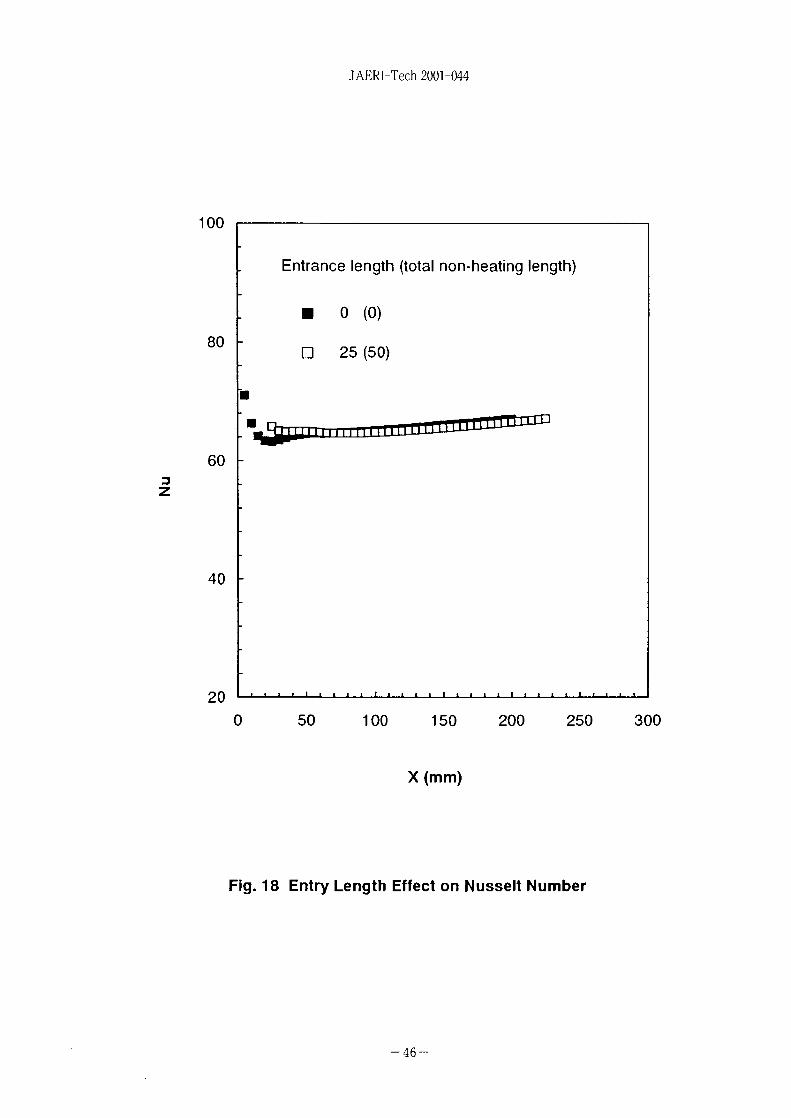
JAERI-Tech 2001-044
100
80
603Z
40
Entrance length (total non-heating length)
• 0 (0)
• 25 (50)
2 0 I • • • • i
0 50 100 150 200 250 300
X(mm)
Fig. 18 Entry Length Effect on Nusselt Number
- 4 6 -

JAERI-Tech 2001-044
-J-i-i-'-J f •—hH—
! • ; ' ! ;
-V—4 -r~I-"(~+~r
.1 .j
" I ! iTITi T Tj T"t JTirrnrmh
I • • ' . ' I ' ' 1 !T
••••••^•••••••••••••••
~-"" *••••••••••••»•
D..10
Re=7000, H=1.2mm
3t*
;iTY MAGNITUDE
504. M X - 4«5?e.MN-0.1935E-01
4,57842533.32?3,6013,2?62,3502.6242,2331.9731-8481.322
0,33830.67060,34500.1935E-01
Fig. 19 Compytational Grid (17 x 2000) of Rib-Royghened Geometryand Velocity Magnityde
- 4 7 -

JAERI-Tech 2001-044
0.1 -
0.01 -
0.001
6000 7000 8000
Re
1 1
1 1
I
--
1 1
1 1
1 1
o
•
1 1 1 1 1
o•
•
o
•
Rib SJD.K -Rib Expt.Smooth STD.
- Blasius
i i i r i
£
K -e
•
9000 10000
Fig. 20 Comparison of Calculated and ExperimentalFrictional Pressure Drops
- 4 9 -

(si) t
*
ft
«T/Jftit
1 SIS
ft
?
wRSItift.
H ftft
lii ft
ft ft
+
T
7"
7
X
£ ft- h
O -7 7
ft1
y ^
IV t
y x
•y rx 7 y T
ry
7
y
y
55 ^"
mkgsAK
molcd
rad
sr
S3
ft
n; )JLJ.IV
L *
UfA.
a y
«
-f y-t ^
)t
ft
ft
7 . JE
+'-.fi», *, WL *t
« , m
a K9 9 9V
9 9 9 y•y 9 x £
w
a
•(Si
•X
mitX
SMIt
*lftft
—
•y
7
9
* •
7
y7
X
- N
•b
,v
9
•y
« ft
J - I-
^ -
• y
— D
r 7
— > yx —
X
y ')
y
y
IV
y
K/.X
7
^ y •? x / t- /
9
9 U-
Ix
- ^<IV
y
X
id*!
HzNPaJWCVF
ns
WbTH
tlmlx
BqGySv
(fe© SI W-{iL
s - 'm-kg/s2
N/m2
N-mJ/sA sW/AC/VV/AA/VV-sWb/m2
Wb/A
cd- srlm/m2
s"'J/kgJ/kg
« ft7 j t Bvf , U
It, », »
^ yW. 1- * 'i/ I-
min, h, d
1, L
t
eV
u
1 eV=1.60218x 10 19J
1 u-1.66054x 10" kg
114 SI £ ft ft if I
•A V 9' %.
,<
,<
fi
+ ^u y h7
ft
'j
y
y
-
y
K/.
s5 f
Ab
barGalCiR
radretn
A=0.1 nm=10-"m
b=100fm'=10-2'm2
bar=0.1MPa=10sPa
lCi=3.7xlO"Bq
1 R=2.58xlO-'C/kg
10"10"1012
10'10'103
102
10'
10"'
10 2
io-3
10 '
io-9
io- '2
10""
10""
X
¥
•f
X
-fe
;
X
e7
T
Bits
9 *t•?
7
ftfta
•y
y x
u-f 7 a
/Z2
h
EPTGMk
h
da
dcmI!
n
Pfa
(/£)
2. * 4 IC ( i f t g ,
3. bar l i ,
fcfcX. 1 eV
7-iv, ^9
, barntij;
rem=l cSv= 10 2Sv
/J N( = 10bdyn)
1
9.80665
4.44822
kgf
0.101972
1
0.453592
lbf
0.224809
2.20462
1
tt H 1 Pa-s(N-s/m2)=10P(*TX-)(g/(cm-s))
ftlttlt lm2 /s-10'St(X h -9 x)(Cm 2 /s)
w
MPaOlObar)
1
0.0980665
0.101325
1.33322 x 10"4
6.89476 x 10"3
kgf/cm!
10.1972
1
1.03323
1.35951 x 10"3
7.03070 x 10 2
atm
9.86923
0.967841
1
1.31579 x 10"'
6.80460 x 10~2
mmHg(Torr)
7.50062 x 10³
735.559
760
1
51.7149
lbf/in!(psi)
145.038
14.2233
14.6959
1.93368 x 10"2
1
X
IV
1
l±
•ft
J ( = 10 'erg)
1
9.80665
3.6x10'
4.18605
1055.06
1.35582
1.60218 x 1 0 "
kgf-m
0.101972
1
3.67098 x 10s
0.426858
107.586
0.138255
1.63377 x 10"20
kW- h
2.77778 x 10"'
2.72407 x 10"6
1
1.16279 x 10"'
2.93072 x 10"4
3.76616 x 10"7
4.45050 x 10"2t
caKitlft)
0.238889
2.34270
8.59999 x 10 s
1
252.042
0.323890
3.82743 x 10"2°
Btu
9.47813 x 10"4
9.29487 x 10"3
3412.13
3.96759x 10"3
1
1.28506 x 10"3
1.51857x10""
ft • lbf
0.737562
7.23301
2.65522 x 10'
3.08747
778.172
1
1.18171 x l O " "
eV
6.24150 x l O ' e
6.12082x10"
2.24694 x 10"
2.61272x10"
6.58515 x 10²¹
8.46233 x 10"
1
Bq
1
3.7 x 10'"
Ci
2.70270 x 10""
1
US
m
Gy
1
0.01
rad
100
1
C/kg
2.58 x 10"
3876
1
leal = 4.18605 J ( I t i t t t )
= 4.184 J mitf)
= 4.1855 J (15 X)
1 PS
= 75 kgf-m/s
= 735.499 W
1
0.01
100
1
26BS4)

Analytical Study of Narrow Channel Flow for a Spallation Target System Design