Embed Size (px)
Citation preview
Analyzing Vehicle Movements with Vehicle
Tracking 2015 Mike Hutt – Autodesk
CV5297-L Vehicle Tracking is a very comprehensive transportation analysis and design solution for
vehicle swept path analysis. It enables engineers, designers, and planners to evaluate vehicle movements on transportation or site design projects. This class aims to aid professionals in utilizing Vehicle Tracking’s swept-path tools, including a grounding in the foundational concepts of swept path analysis and vehicle behavior. Focus is on introducing maximum benefit through working with dynamic workflows to speed up design and add modeling intelligence.
Learning Objectives At the end of this class, you will be able to:
Analyze vehicle movements
Visualize vehicle movements within designs in 3D
Perform vehicle-to-surface conflict detection
Speed up transportation-design processes
About the Speaker
Mike Hutt has worked on engineering projects, with experience served at a number of software vendors,
for over 13 years; with specific expertise in the transportation and automotive industries. Mike currently
sits within Autodesk’s Infrastructure Sales Team covering solutions such as Vehicle Tracking, Structural
Bridge Design and InfraWorks 360, in this role he helps Autodesk’s customers realize greater potential
through valuable technology partnerships and the strategic alignment of innovative new solutions against
their business goals.
Analyzing Vehicle Movements with Vehicle Tracking 2015
2
Analyze vehicle movements
Basic Swept Path Theory
Vehicle Tracking swept path simulations utilize various methodologies, below is an introduction
of those that have greater influence and designers should be aware of.
The Ackerman principle
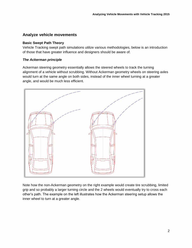
Ackerman steering geometry essentially allows the steered wheels to track the turning
alignment of a vehicle without scrubbing. Without Ackerman geometry wheels on steering axles
would turn at the same angle on both sides, instead of the inner wheel turning at a greater
angle, and would be much less efficient.
Note how the non-Ackerman geometry on the right example would create tire scrubbing, limited
grip and so probably a larger turning circle and the 2 wheels would eventually try to cross each
other’s path. The example on the left illustrates how the Ackerman steering setup allows the
inner wheel to turn at a greater angle.
Analyzing Vehicle Movements with Vehicle Tracking 2015
3
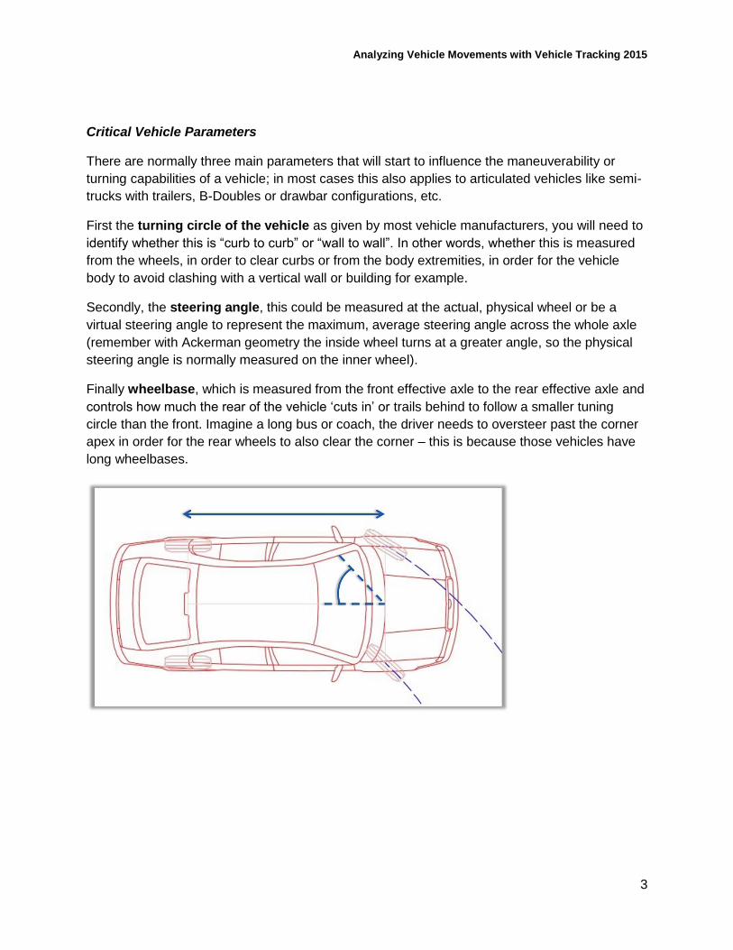
Critical Vehicle Parameters
There are normally three main parameters that will start to influence the maneuverability or
turning capabilities of a vehicle; in most cases this also applies to articulated vehicles like semi-
trucks with trailers, B-Doubles or drawbar configurations, etc.
First the turning circle of the vehicle as given by most vehicle manufacturers, you will need to
identify whether this is “curb to curb” or “wall to wall”. In other words, whether this is measured
from the wheels, in order to clear curbs or from the body extremities, in order for the vehicle
body to avoid clashing with a vertical wall or building for example.
Secondly, the steering angle, this could be measured at the actual, physical wheel or be a
virtual steering angle to represent the maximum, average steering angle across the whole axle
(remember with Ackerman geometry the inside wheel turns at a greater angle, so the physical
steering angle is normally measured on the inner wheel).
Finally wheelbase, which is measured from the front effective axle to the rear effective axle and
controls how much the rear of the vehicle ‘cuts in’ or trails behind to follow a smaller tuning
circle than the front. Imagine a long bus or coach, the driver needs to oversteer past the corner
apex in order for the rear wheels to also clear the corner – this is because those vehicles have
long wheelbases.
Analyzing Vehicle Movements with Vehicle Tracking 2015
4
Transitions
Accurately analyzing turning movement’s means taking account certain realisms.
First, we limit the turning capabilities to follow simulated steering input for drivers – this means
that a vehicle cannot simply switch to the optimum turning angle instantaneously; we must allow
enough time for the driver to have turned the steering wheel around to that position. Otherwise
we risk designing sites that require unrealistic steering capabilities to navigate.
Think about it this way, how long does it really take you to turn from full steering lock one side,
all the way to the other side (normally around 4 complete turns of a steering wheel) – you
certainly cannot do this instantly as if the steering were controlled by a switch or joystick. If the
average time for a PCE of 4 seconds sounds too quick to you, try it with your hands in front of
you at a realistic speed – it takes longer than you would think!
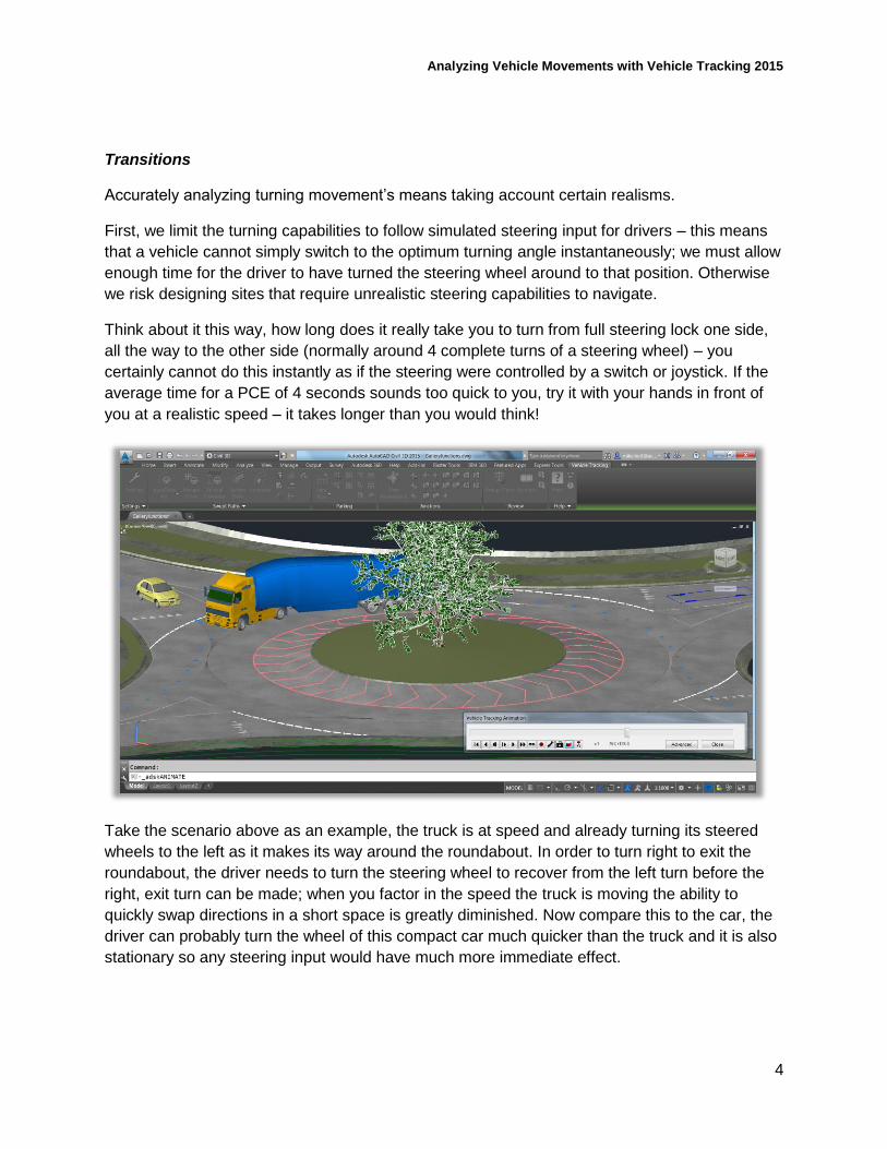
Take the scenario above as an example, the truck is at speed and already turning its steered
wheels to the left as it makes its way around the roundabout. In order to turn right to exit the
roundabout, the driver needs to turn the steering wheel to recover from the left turn before the
right, exit turn can be made; when you factor in the speed the truck is moving the ability to
quickly swap directions in a short space is greatly diminished. Now compare this to the car, the
driver can probably turn the wheel of this compact car much quicker than the truck and it is also
stationary so any steering input would have much more immediate effect.
Analyzing Vehicle Movements with Vehicle Tracking 2015
5
Transitions (continued)
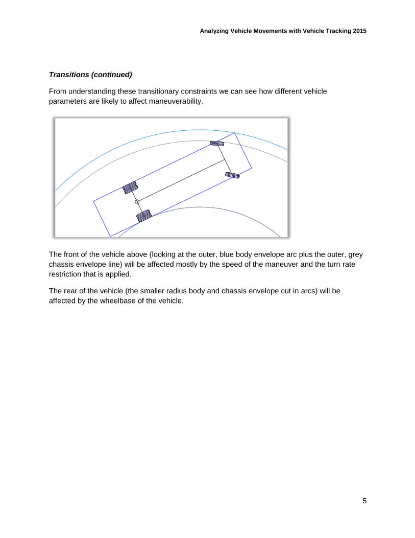
From understanding these transitionary constraints we can see how different vehicle
parameters are likely to affect maneuverability.
The front of the vehicle above (looking at the outer, blue body envelope arc plus the outer, grey
chassis envelope line) will be affected mostly by the speed of the maneuver and the turn rate
restriction that is applied.
The rear of the vehicle (the smaller radius body and chassis envelope cut in arcs) will be
affected by the wheelbase of the vehicle.
Analyzing Vehicle Movements with Vehicle Tracking 2015
6
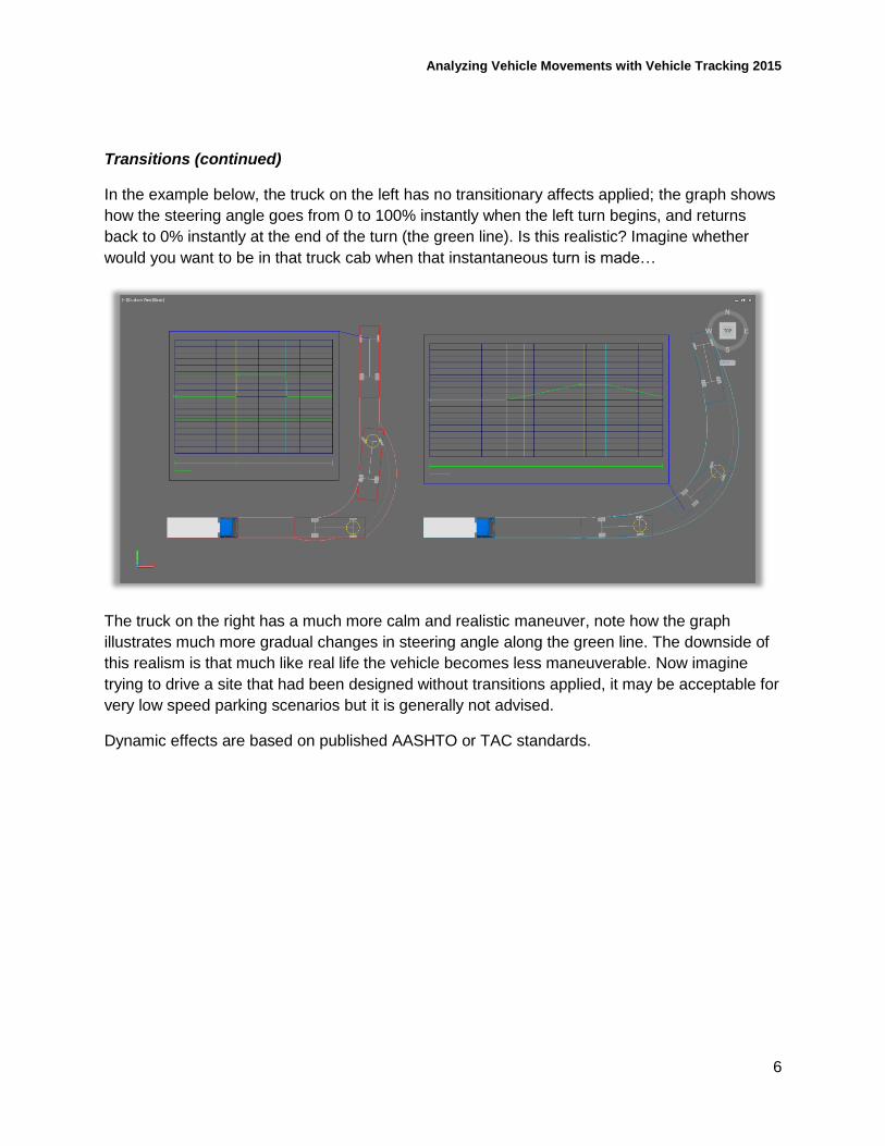
Transitions (continued)
In the example below, the truck on the left has no transitionary affects applied; the graph shows
how the steering angle goes from 0 to 100% instantly when the left turn begins, and returns
back to 0% instantly at the end of the turn (the green line). Is this realistic? Imagine whether
would you want to be in that truck cab when that instantaneous turn is made…
The truck on the right has a much more calm and realistic maneuver, note how the graph
illustrates much more gradual changes in steering angle along the green line. The downside of
this realism is that much like real life the vehicle becomes less maneuverable. Now imagine
trying to drive a site that had been designed without transitions applied, it may be acceptable for
very low speed parking scenarios but it is generally not advised.
Dynamic effects are based on published AASHTO or TAC standards.
Analyzing Vehicle Movements with Vehicle Tracking 2015
7
Different Drive Modes
When a vehicle is driven through a route, the driver doesn’t use just one single type of turning
maneuver, they react with multiple maneuvering skills according to the geometry of the road or
site.
So we need to do the same when designing sites and simulating continuous turning
movements. We also need to model the movements as a continuous simulation; this means that
each maneuver is connected and not treated as separate. This is important as this also places
constraints on the turning capability of a vehicle. Think about a car park, intersection or delivery
bay where a right hand turn can immediately develops into a left hand turn or vice versa; when
the vehicle is exiting the initial right hand turn the steered wheels are turned right, so in order for
the vehicle to turn left the wheels first need to recover to a straight ahead angle and then turn
left. This means the driver needs to turn earlier on and the vehicle subsequently needs more
space.
So in Vehicle Tracking we utilize different drive modes according to the geometry that we’re
dealing with:
AutoDrive – this is normally the best option as it enables you to switch between drive
modes dynamically just like a real driver
o AutoDrive Arc – this starts in arc mode to create smooth arc turns between each
target point. Target points are simply the locations where you click with your left
mouse button as a point that the vehicle must pass through.
o AutoDrive Bearing – starting in bearing mode is advised for when you need to
turn through a specified angle such as 90 degree road alignments or 60 degree
parking angles, etc.
As an extension of this mode, you are also given the option of picking an
alignment to target for your turn, this is a great tool to use when you need
to maneuver parallel to an alignment. For example, when lining up into a
traffic lane, or when reversing an articulated vehicle into a loading bay.
Manual drive is rarely used nowadays, this mode enables you to use an on screen tablet
to move the vehicle according to your mouse position on the tablet (move your cursor
forward a little to move forward slowly, a little more to pick up speed and move left to
turn left, etc.). This drive mode pre-dates AutoDrive and is not generally recommended
unless you want to complete a small maneuver in a complicated abnormal loads vehicle,
for example, that requires very detailed inputs.
Follow drive – this mode does as you would expect and follows an alignment (which may
be a simple polyline) until the line ends or until Vehicle Tracking computes that the
maneuver cannot be accomplished at the current speed and within current transitionary
settings. You can offset tracking positions from alignments to enable you to follow curb
lines or lane markings as needed. A specific version of follow drive can be used with
airplanes, in order to follow taxi markings through airfields.
Analyzing Vehicle Movements with Vehicle Tracking 2015
8
Different Drive Modes (continued)
Script drive allows you to write scripts that control vehicle paths, this is again less
commonly used but may be useful if you need to repeat the exact same set of
maneuvers with a large number of different vehicles. The Vehicle Tracking user guide
contains script language help.
Templates – templates are static blocks that can be placed in drawings, exported to files
or printed directly. It’s not recommended to design geometry based upon a static turning
template over a dynamic swept path simulation, but templates are useful tools to present
the general swept path capabilities of vehicles - especially when comparing multiple
vehicles side by side within documentation.
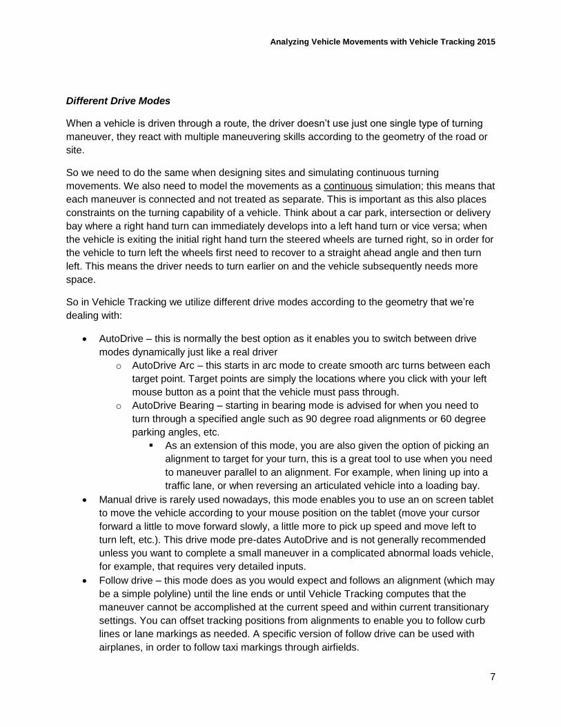
There is a further drive mode not listed above called Guided Drive, this is specifically for rail
vehicles and differs from Follow Drive in that each rail car unit on the vehicle is made to follow
the tracks alignment, whereas with follow drive only one single tracking point (such as the
drivers eye or the center of the front axle) follows the alignment and the rest of the vehicle’s
position is calculated accordingly.
Analyzing Vehicle Movements with Vehicle Tracking 2015
9
Visualize vehicle movements within designs in 3D
It’s a relatively simple process to visualize a swept path within Vehicle Tracking
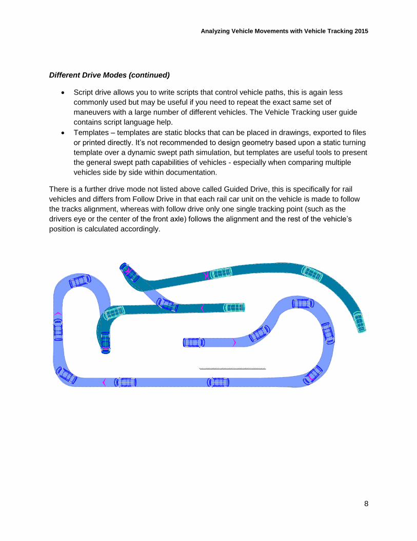
Presentation
First experiment with this section of the Vehicle Tracking ribbon, within literally seconds, you
can improve your presentation by including plan vehicle outlines along your swept path that
illustrate vehicles bodies, chassis’, and other items such as visibility splays. You can also insert
a vehicle diagram for the current vehicle, a steering and articulation graph and even take a few
extra minutes to alter the presentation of the vehicle path style to match your normal CAD
template.
TIP Hover over buttons on the ribbon to see a tooltip explanation of their purpose.
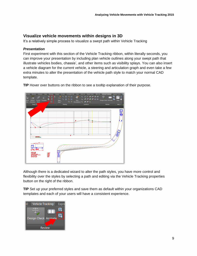
Although there is a dedicated wizard to alter the path styles, you have more control and
flexibility over the styles by selecting a path and editing via the Vehicle Tracking properties
button on the right of the ribbon.
TIP Set up your preferred styles and save them as default within your organizations CAD
templates and each of your users will have a consistent experience.
Analyzing Vehicle Movements with Vehicle Tracking 2015
10
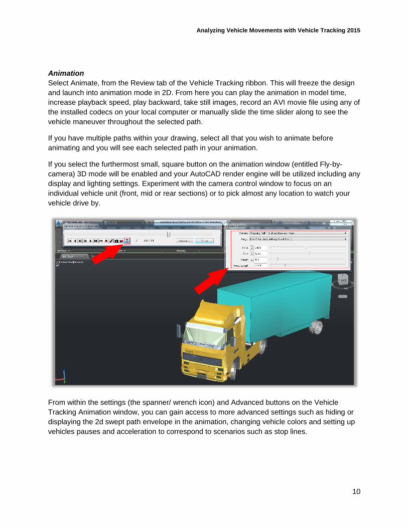
Animation
Select Animate, from the Review tab of the Vehicle Tracking ribbon. This will freeze the design
and launch into animation mode in 2D. From here you can play the animation in model time,
increase playback speed, play backward, take still images, record an AVI movie file using any of
the installed codecs on your local computer or manually slide the time slider along to see the
vehicle maneuver throughout the selected path.
If you have multiple paths within your drawing, select all that you wish to animate before
animating and you will see each selected path in your animation.
If you select the furthermost small, square button on the animation window (entitled Fly-by-
camera) 3D mode will be enabled and your AutoCAD render engine will be utilized including any
display and lighting settings. Experiment with the camera control window to focus on an
individual vehicle unit (front, mid or rear sections) or to pick almost any location to watch your
vehicle drive by.
From within the settings (the spanner/ wrench icon) and Advanced buttons on the Vehicle
Tracking Animation window, you can gain access to more advanced settings such as hiding or
displaying the 2d swept path envelope in the animation, changing vehicle colors and setting up
vehicles pauses and acceleration to correspond to scenarios such as stop lines.
Analyzing Vehicle Movements with Vehicle Tracking 2015
11
Perform vehicle-to-surface conflict detection
Requirements
You can use Vehicle Tracking to drive vehicles across AutoCAD Civil 3D corridors and surfaces,
in addition to this you can also drive across AutoCAD surfaces. There is no need to rework
surface or terrain geometry into different formats in order to analyze or visualize ground conflict.
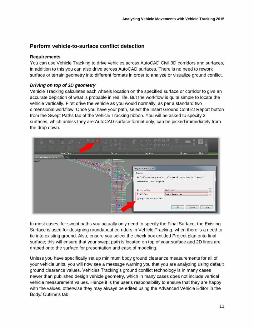
Driving on top of 3D geometry
Vehicle Tracking calculates each wheels location on the specified surface or corridor to give an
accurate depiction of what is probable in real life. But the workflow is quite simple to locate the
vehicle vertically. First drive the vehicle as you would normally, as per a standard two
dimensional workflow. Once you have your path, select the Insert Ground Conflict Report button
from the Swept Paths tab of the Vehicle Tracking ribbon. You will be asked to specify 2
surfaces, which unless they are AutoCAD surface format only, can be picked immediately from
the drop down.
In most cases, for swept paths you actually only need to specify the Final Surface; the Existing
Surface is used for designing roundabout corridors in Vehicle Tracking, when there is a need to
tie into existing ground. Also, ensure you select the check box entitled Project plan onto final
surface; this will ensure that your swept path is located on top of your surface and 2D lines are
draped onto the surface for presentation and ease of modeling.
Unless you have specifically set up minimum body ground clearance measurements for all of
your vehicle units, you will now see a message warning you that you are analyzing using default
ground clearance values. Vehicles Tracking’s ground conflict technology is in many cases
newer than published design vehicle geometry, which in many cases does not include vertical
vehicle measurement values. Hence it is the user’s responsibility to ensure that they are happy
with the values, otherwise they may always be edited using the Advanced Vehicle Editor in the
Body/ Outline’s tab.
Analyzing Vehicle Movements with Vehicle Tracking 2015
12
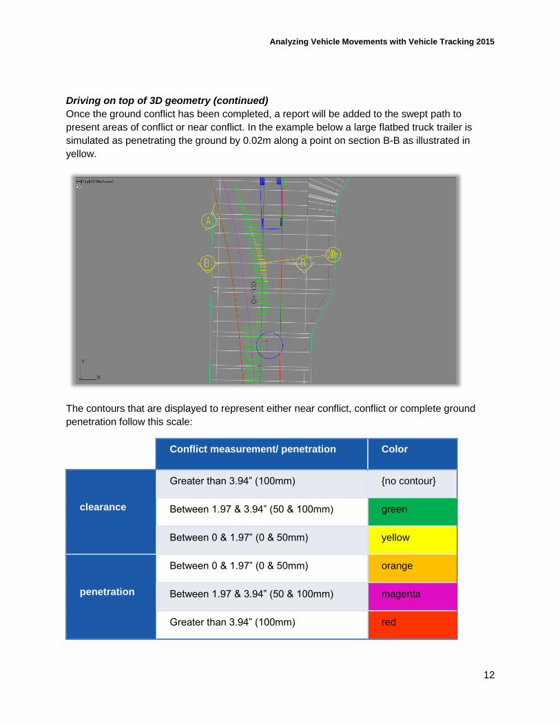
Driving on top of 3D geometry (continued)
Once the ground conflict has been completed, a report will be added to the swept path to
present areas of conflict or near conflict. In the example below a large flatbed truck trailer is
simulated as penetrating the ground by 0.02m along a point on section B-B as illustrated in
yellow.
The contours that are displayed to represent either near conflict, conflict or complete ground
penetration follow this scale:
Conflict measurement/ penetration Color
clearance
Greater than 3.94” (100mm) {no contour}
Between 1.97 & 3.94” (50 & 100mm) green
Between 0 & 1.97” (0 & 50mm) yellow
penetration
Between 0 & 1.97” (0 & 50mm) orange
Between 1.97 & 3.94” (50 & 100mm) magenta
Greater than 3.94” (100mm) red
Analyzing Vehicle Movements with Vehicle Tracking 2015
13
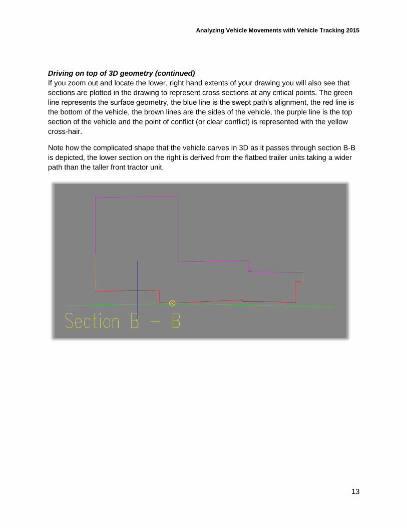
Driving on top of 3D geometry (continued)
If you zoom out and locate the lower, right hand extents of your drawing you will also see that
sections are plotted in the drawing to represent cross sections at any critical points. The green
line represents the surface geometry, the blue line is the swept path’s alignment, the red line is
the bottom of the vehicle, the brown lines are the sides of the vehicle, the purple line is the top
section of the vehicle and the point of conflict (or clear conflict) is represented with the yellow
cross-hair.
Note how the complicated shape that the vehicle carves in 3D as it passes through section B-B
is depicted, the lower section on the right is derived from the flatbed trailer units taking a wider
path than the taller front tractor unit.
Analyzing Vehicle Movements with Vehicle Tracking 2015
14
Speed up transportation-design processes
Understanding Vehicle Tracking
Vehicle Tracking is an ‘add-on’ software that requires a host CAD platform to run. The maximum
benefit is gained through running in AutoCAD Civil 3D as additional functionality is Vehicle
Tracking is made available, such as the ground conflict analysis that we have already covered.
However, although Vehicle Tracking runs on top of other software, it contains its own specific
settings, options and control parameters. Whilst you can get by without taking much note of
these, by understanding them a little, a marked improvement in design efficiency can be gained.
Settings
Vehicle Tracking contains two main levels of settings allowing you to set up your work
environment as you wish, but also to accommodate project team or client specific needs in
single or temporary project files and templates.
System settings
o These are the default, ‘global’ settings that apply to the Vehicle Tracking
installation on a computer or workstation
o These can be saved into corporate CAD templates for organization wide use or
for sharing project file requirements with sub-contractors for example
Drawing settings
o These are saved in, and remain in, the current drawing/ project file
o These can be exported separately
o Custom design standards or entire vehicle libraries can also be shared inside
drawing files
Note: Standards and libraries can also be shared outside drawing files within specific data
library files.
Analyzing Vehicle Movements with Vehicle Tracking 2015
15
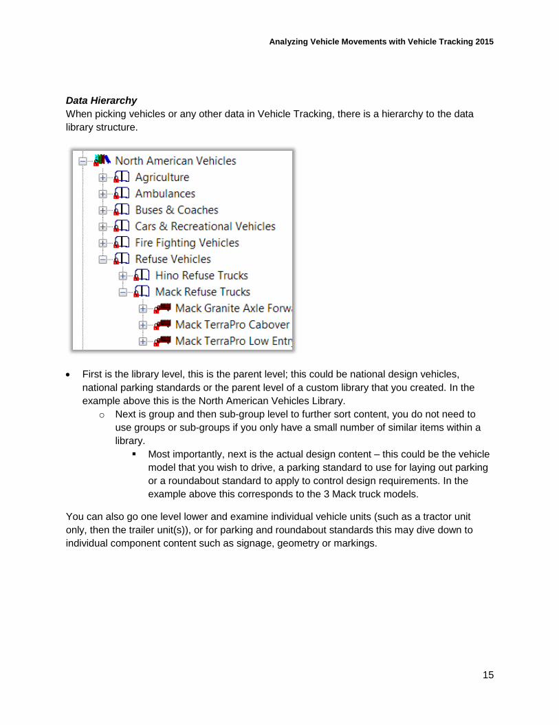
Data Hierarchy
When picking vehicles or any other data in Vehicle Tracking, there is a hierarchy to the data
library structure.
First is the library level, this is the parent level; this could be national design vehicles,
national parking standards or the parent level of a custom library that you created. In the
example above this is the North American Vehicles Library.
o Next is group and then sub-group level to further sort content, you do not need to
use groups or sub-groups if you only have a small number of similar items within a
library.
Most importantly, next is the actual design content – this could be the vehicle
model that you wish to drive, a parking standard to use for laying out parking
or a roundabout standard to apply to control design requirements. In the
example above this corresponds to the 3 Mack truck models.
You can also go one level lower and examine individual vehicle units (such as a tractor unit
only, then the trailer unit(s)), or for parking and roundabout standards this may dive down to
individual component content such as signage, geometry or markings.
Analyzing Vehicle Movements with Vehicle Tracking 2015
16
Editing
This is the most important area and the area where Vehicle Tracking’s workflow benefits really
come into their own. Unless you require a specific text font that Vehicle Tracking cannot
accommodate, there seems no immediate reason to ever explode or delete a vehicles swept
path. If you think this is a strong statement, read on…
Firstly, each new swept path is by default placed onto a newly created layer in order to toggle
quickly between paths and only display the relevant data. Secondly, once a path is exploded, all
live simulation, visibility, speed related and presentation options are lost and the object’s value
is limited to line work. Perhaps most importantly, there is no longer an audit trail of how the path
was created, edited and if limitations have been overridden.
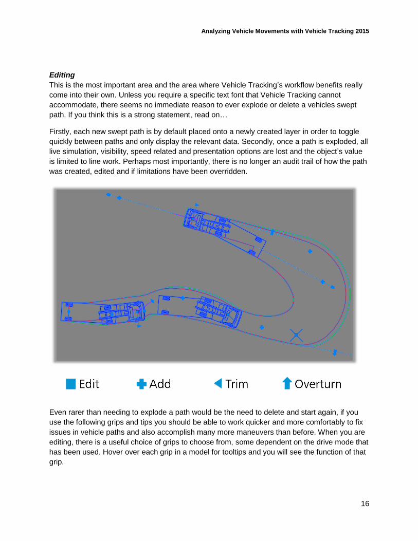
Even rarer than needing to explode a path would be the need to delete and start again, if you
use the following grips and tips you should be able to work quicker and more comfortably to fix
issues in vehicle paths and also accomplish many more maneuvers than before. When you are
editing, there is a useful choice of grips to choose from, some dependent on the drive mode that
has been used. Hover over each grip in a model for tooltips and you will see the function of that
grip.
Analyzing Vehicle Movements with Vehicle Tracking 2015
17
Editing (continued)
TIP Don’t try to get the path right first time, it’s often quicker and easier to go back over the path
and fine tune afterward.
One of the first grips that you will generally always see are the square grips, these are the
target points which are derived from your left mouse click positions when creating the swept
path; these are points that the vehicles tracking point (by default the center of the front axle)
must pass through.
TIP Don’t get trigger happy and click too much when creating an initial vehicle swept path, as
this creates too much constrain on the path; try to only click where necessary. If you find you
have too many target points to drive through because of this, don’t delete and start over; you
can drag a target point onto the next target point to remove it.
The ‘plus’ symbol allows you to add a new target point in an intermediate location This can
be handy when going back and fine tuning the vehicle location or orientation in the middle of
the path. This will create a new and totally standard, editable square grip as above.
In addition to these you will see triangular grips at the start and end of the path, these can
be used to crop the start or end chainages of the path.
If bearing turns were used in the path you will also see side and exit overturn grips, these
increase or decrease the amount of oversteer that the vehicle uses to swing out wide before
the turn or swing out wide past the turn. These are very useful for clearing items such as
traffic islands or curbs on the inside of a turn.
TIP Another handy tip is for extending a path. Often, you will need to pick up where you or a
colleague left off and continue an existing path. In the interests of modelling a continuous
maneuver, you can simply select the path so that it is active and then select your drive mode
from the Vehicle Tracking ribbon; rather than starting a new path you will resume where the
existing path currently ends.
Analyzing Vehicle Movements with Vehicle Tracking 2015
18
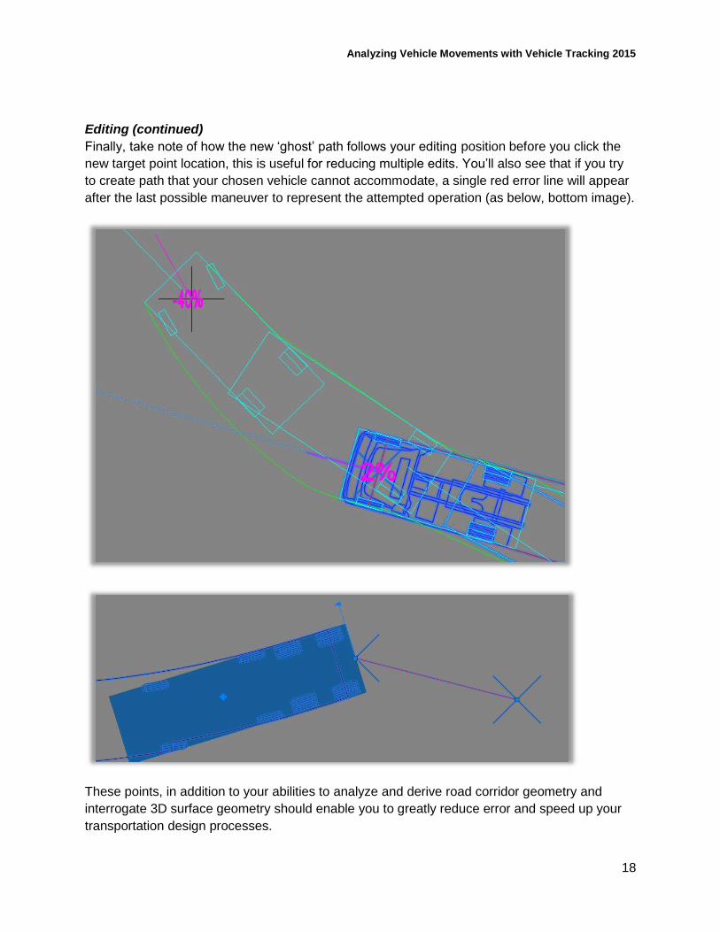
Editing (continued)
Finally, take note of how the new ‘ghost’ path follows your editing position before you click the
new target point location, this is useful for reducing multiple edits. You’ll also see that if you try
to create path that your chosen vehicle cannot accommodate, a single red error line will appear
after the last possible maneuver to represent the attempted operation (as below, bottom image).
These points, in addition to your abilities to analyze and derive road corridor geometry and
interrogate 3D surface geometry should enable you to greatly reduce error and speed up your
transportation design processes.