Embed Size (px)
Citation preview
Available online at www.sciencedirect.com
ScienceDirect
Journal of Electrocardiology 49 (2016) 649 – 657www.jecgonline.com
Review
Anatomical approach to permanent His bundle pacing: Optimizing Hisbundle capture☆,☆☆,★
Pugazhendhi Vijayaraman, MD, a,⁎ Gopi Dandamudi, MDb
a Geisinger Heart Institute, Wilkes Barre, PAb Indiana University School of Medicine, Indianapolis, IN
Abstract Permanent His bundle pacing is a physiological alternative to right ventricular pacing. In this article
☆ Disclosures: PVGD (Medtronic-Speake
☆☆ Acknowledgem★ Funding Sourc⁎ Corresponding
Institute, Geisinger WMountain Blvd, Wilke
E-mailaddresses:
http://dx.doi.org/10.100022-0736/© 2016 El
we describe our approach to His bundle pacing in patients with AV nodal and intra-Hisianconduction disease. It is essential for the implanters to understand the anatomic variations of the Hisbundle course and its effect on the type of His bundle pacing achieved. We describe several caseexamples to illustrate our anatomical approach to permanent His bundle pacing in this article.© 2016 Elsevier Inc. All rights reserved.
Keywords: His bundle pacing; Selective His bundle pacing; Nonselective His bundle pacing; Intra-Hisian AV block
Introduction
Permanent His bundle pacing (HBP) is the mostphysiological form of ventricular pacing. Right ventricularpacing is known to cause ventricular dyssynchrony, heartfailure and increased mortality [1–4]. By maintainingconduction through the normal His-Purkinje system, HBPprevents ventricular dyssynchrony and may reduce heartfailure. Deshmukh et al., demonstrated the feasibility ofpermanent HBP in patients undergoing AV node ablation inthe year 2000 [5]. Since then, several investigators havereported successful HBP in a significant number of patients[6–10]. Nonetheless, widespread adoption of this techniquehas remained elusive.
Anatomy of the His bundle
The His bundle begins from the AV nodal tissue andcourses along the membranous septum on the right sidebefore penetrating to the left side on the crest of the muscularportion of the inter-ventricular septum. It is essential for theimplanters to understand that a significant length of theproximal His bundle rests on the right atrial-left ventricularpart of the membranous septum, which is above the tricuspid
(Medtronic-Speaker, Boston Scientific-Advisory board);r, Bohringer-Ingelheim-Speaker).ent: None.e: None.author at: Cardiac Electrophysiology, Geisinger Heartyoming Valley Medical Center, MC 36-10, 1000 Es Barre, PA, [email protected], [email protected]
16/j.jelectrocard.2016.07.003sevier Inc. All rights reserved.
valve plane. Several anatomical variations of the distal Hisbundle course have been described. Our experience ofpermanent His bundle pacing in more than 400 consecutivepatients has enabled us to understand these variations andtheir impact on achieving selective or non-selective Hisbundle pacing. Kawashima and Sasaki investigated thelocational variation of the His bundle in 105 elderly humanhearts and described three distinct patterns [11]. In type I(46.7% of 105 cases), the His bundle consistently coursedalong the lower border of the membranous part of theinterventricular septum but was covered with a thin layer ofmyocardial fibers spanning from the muscular part of theseptum. In type II (32.4%) the His bundle was apart from thelower border of the membranous part of the interventricularseptum and ran within the interventricular muscle. In type III(21%), the His bundle was immediately beneath theendocardium and coursed onto the membranous part of theinterventricular septum (naked His bundle). These variationsin the course of the His bundle help explain the differentpatterns of His bundle capture.
Definitions
There have been several different descriptions of Hisbundle capture. In order to provide uniformity, werecommend the following definitions based on the originaldescriptions published by Williams et al. [12], andDeshmukh et al. [5].
Selective His bundle pacing (S-HBP) is defined byventricular activation occurring solely over theHis-Purkinje system. S-HBP can be recognized by the
650 P. Vijayaraman, G. Dandamudi / Journal of Electrocardiology 49 (2016) 649–657
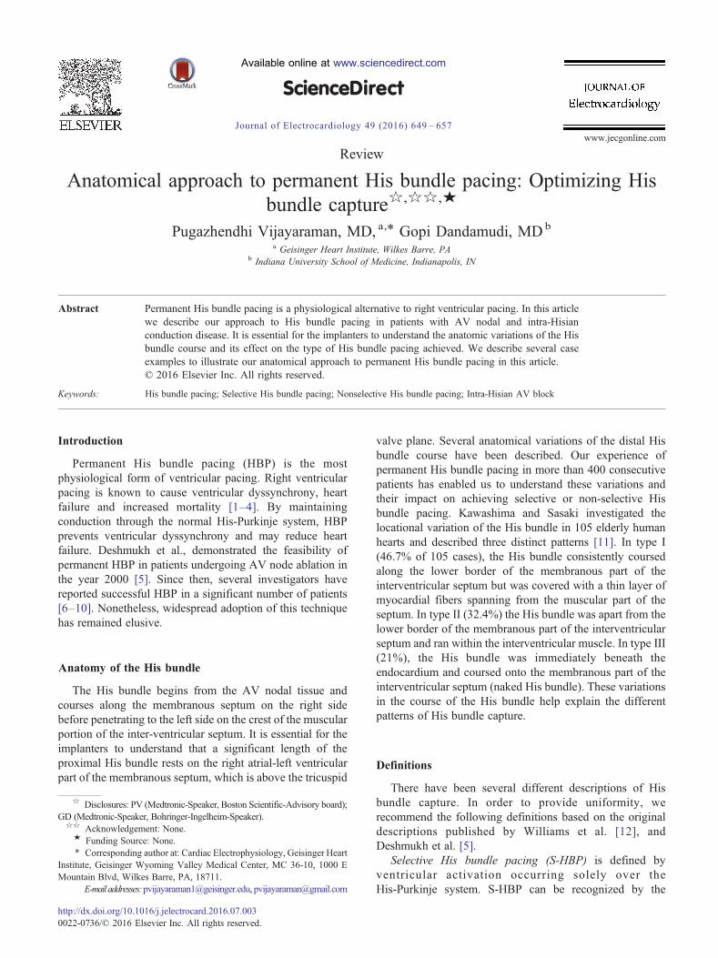
following criteria: [1] His-Purkinje mediated cardiac activa-tion and repolarization, as evidenced by electrocardiographic(ECG) concordance of QRS and T wave complexes similarto baseline; [2] the paced-ventricular interval is almostidentical to the His-ventricular interval (Fig. 1). S-HBP hasbeen variously described in literature as direct HBP,pure-His pacing and selective-direct HBP. It is importantto note that S-HBP may result in normalization ofpre-existing right or left bundle branch block with T wavememory changes [13,14].
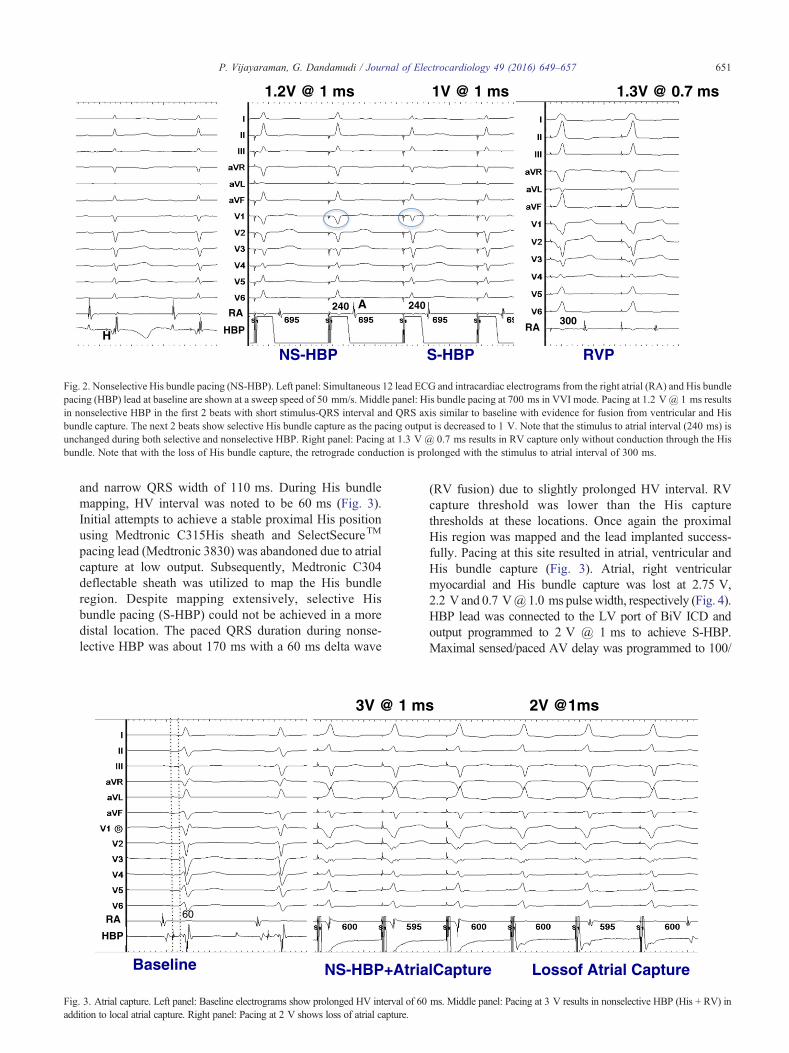
Non-selectiveHis bundle pacing (NS-HBP) is defined basedon capture of basal ventricular septum in addition to Hisbundle capture as: [1] no isoelectric interval between pacingstimulus and QRS; [2] recording His bundle electrogram onthe pacing lead; [3] electrical axis of the paced QRSconcordant with the electrical axis of the spontaneous QRS(if known); [4] narrowing of QRS at higher output due tofusion between RV and His bundle capture and widening ofQRS at lower output due to loss of His bundle capture orvice-versa (Fig. 2). Paced QRS complexes may be narrowerthan the baseline rhythm in the setting of pre-existing BBBor infra-nodal AV block [10,15]. NS-HBP has variouslybeen described in literature as paraHisian pacing [5],pure-paraHisian pacing [16], nonselective-direct HBP [17].Significant confusion still exists regarding paraHisian pacingas several authors do not report actual His bundle capturethresholds (the lowest pacing output at which QRSnarrowing occurs) which may or may not be higher thanthe RV capture threshold [18]. In order to avoid confusion,when His bundle capture is present with fusion, it should bereferred to as nonselective HBP (NS-HBP) and both HB andRV capture thresholds should be specified.
Anatomical approach to His bundle pacing
We have previously described our His bundle pacingtechnique utilizing unipolar mapping from the pacing
H
HV 55 ms Stim-V 55 ms
HBP
Fig. 1. Selective His bundle pacing (S-HBP). The left panel shows simultaneous 1pacing lead at a sweep speed of 100 mm/s. The HV interval is 55 ms. The right panewith an isoelectric stimulus-QRS interval of 55 ms.
electrode without using an electrophysiology mappingcatheter [8,9]. In patients with normal His-Purkinje conduc-tion, our approach is to achieve selective His bundle pacing.In our experience, we are able to achieve S-HBP in about50% of these patients. Our ability to achieve S-HBP islimited by atrial capture, atrial oversensing and/or ventricularundersensing in the proximal His bundle region. If any of theabove issues are noted at the time of implant, the lead ispositioned slightly more distally. Often the distal His bundleis covered by a thin layer of myocardial fibers spanning fromthe muscular part of the interventricular septum (KawashimaType I His bundle) [11]. In these patients we see minimalventricular fusion and the paced QRS duration is usually lessthan 120 ms. In a third of patients, the His bundle lies withinthe muscular interventricular septum (type II), whereselective HBP is not feasible. In this situation, NS-HBP isachieved with RV capture threshold lower than the Hiscapture threshold. In patients with the naked His bundle(type III), significant His bundle injury current can beobserved with S-HBP and very low His capture thresholds(b0.5 V). In patients with His-Purkinje conduction disease(bundle branch blocks or intra-Hisian AV block) ourpreference is to achieve NS-HBP. We do not routinely usea RV backup pacing lead in most of our pacemaker implants.By achieving NS-HBP, the right ventricular basal myocar-dial capture can provide a safety back-up pacing should therebe progression of distal Purkinje conduction disease [10].
The following case examples illustrate our anatomicapproach to permanent HBP in specific scenarios.
Case 1: A 74-year-old man with recurrent persistent atrialfibrillation, nonischemic cardiomyopathy, severe LVsystolic dysfunction, EF b20% and class III NYHAsymptoms was referred for AV node ablation andbiventricular ICD implantation. He had previously failedmultiple antiarrhythmic drugs and atrial fibrillationablation. EKG at baseline showed normal PR interval
2-lead electrocardiogram with intracardiac electrogram from the His bundlel demonstrates selective HBP with QRSmorphology identical to the baseline
RARA
H
A 240
300
NS-HBP S-HBP RVP
1.2V @ 1 ms 1V @ 1 ms 1.3V @ 0.7 ms
240
HBP
Fig. 2. Nonselective His bundle pacing (NS-HBP). Left panel: Simultaneous 12 lead ECG and intracardiac electrograms from the right atrial (RA) and His bundlepacing (HBP) lead at baseline are shown at a sweep speed of 50 mm/s. Middle panel: His bundle pacing at 700 ms in VVI mode. Pacing at 1.2 V@ 1 ms resultsin nonselective HBP in the first 2 beats with short stimulus-QRS interval and QRS axis similar to baseline with evidence for fusion from ventricular and Hisbundle capture. The next 2 beats show selective His bundle capture as the pacing output is decreased to 1 V. Note that the stimulus to atrial interval (240 ms) isunchanged during both selective and nonselective HBP. Right panel: Pacing at 1.3 V @ 0.7 ms results in RV capture only without conduction through the Hisbundle. Note that with the loss of His bundle capture, the retrograde conduction is prolonged with the stimulus to atrial interval of 300 ms.
Figadd
651P. Vijayaraman, G. Dandamudi / Journal of Electrocardiology 49 (2016) 649–657
and narrow QRS width of 110 ms. During His bundlemapping, HV interval was noted to be 60 ms (Fig. 3).Initial attempts to achieve a stable proximal His positionusing Medtronic C315His sheath and SelectSecureTM
pacing lead (Medtronic 3830) was abandoned due to atrialcapture at low output. Subsequently, Medtronic C304deflectable sheath was utilized to map the His bundleregion. Despite mapping extensively, selective Hisbundle pacing (S-HBP) could not be achieved in a moredistal location. The paced QRS duration during nonse-lective HBP was about 170 ms with a 60 ms delta wave
Baseline NS-HBP+AtrialCapture Lossof Atrial Capture
3V @ 1 ms 2V @1ms
60
HBP
RA
. 3. Atrial capture. Left panel: Baseline electrograms show prolonged HV interval of 60 ms. Middle panel: Pacing at 3 V results in nonselective HBP (His + RV) inition to local atrial capture. Right panel: Pacing at 2 V shows loss of atrial capture.
(RV fusion) due to slightly prolonged HV interval. RVcapture threshold was lower than the His capturethresholds at these locations. Once again the proximalHis region was mapped and the lead implanted success-fully. Pacing at this site resulted in atrial, ventricular andHis bundle capture (Fig. 3). Atrial, right ventricularmyocardial and His bundle capture was lost at 2.75 V,2.2 V and 0.7 [email protected] ms pulsewidth, respectively (Fig. 4).HBP lead was connected to the LV port of BiV ICD andoutput programmed to 2 V @ 1 ms to achieve S-HBP.Maximal sensed/paced AV delay was programmed to 100/

Nonselective-HBP Selective HBP 100 mm/sec
2.2 V@ 1 ms 1V @1 ms
170 110
NS-HBP S-HBP
HBP
Fig. 4. Output dependent NS-HBP. Left panel: Pacing at 2.2 V and above resulted in NS-HBP with significant fusion. RV capture was lost at lower output withselective His bundle capture. Sweep speed 50 mm/s. Right panel: During NS-HBP, QRS duration is 170 ms from significant RV fusion due to long HV intervalWith S-HBP, QRS width is 110 ms identical to baseline. Sweep speed 100 mm/s. (Same patient as in Fig. 3).
Figpan
652 P. Vijayaraman, G. Dandamudi / Journal of Electrocardiology 49 (2016) 649–657
120 ms to accommodate the HV interval of 60 ms. NS-HBPis generally acceptable in most situations with minimalfusion (≤40 ms). A proximal placement of the HBP lead canlead to significant challenge during AV node ablation. Inpatients undergoing AV node ablation, we prefer that a smallor no atrial electrogram is seen in the HBP lead. AV nodeablation was performed in this patient using a deflectablesheath ensuring that the ablation electrode does not cross thelevel of the ring electrode (Fig. 5). When ablating very closeto the HBP lead, as in this case, we generally pace from theHBP lead at approximately 0.5 V above the HBP threshold(1.5 V @ 1 ms in this patient). Ablation should beterminated if His capture is lost at anytime during theablation. This case illustrates the various challengesassociated with HBP and the need to modify the approachbased on clinical needs and the patient's anatomy.Case 2:An 84-year-old man with a recent onset persistentatrial fibrillation, slow ventricular response (average HR
. 5. Fluoroscopy. Left panel: Anteroposterior fluoroscopic image of the permanent HBP lead in the patient (as in Figs. 3 and 4) with biventricular ICD. Righel: Location of the ablation catheter in relation to the HBP lead in right anterior oblique projection.
.
of 42 bpm), QRS width of 114 ms, LVEF of 40% andNYHA class III symptoms was referred for permanentpacemaker implantation.A dual chamber pacemaker with an HBP lead (ventric-ular) was planned. In patients with high grade AV block,we routinely place the atrial lead in the RV apex duringHis bundle mapping to provide temporary ventricularpacing. During initial mapping we identified a site (A)with a small His electrogram (no atrial signal) whereS-HBP was obtained (Fig. 6). However, the capturethreshold was 2.5 V @ 1 ms at this site. Because of thedifficulty in achieving this location, we decided to furthermap the His bundle region using a second pacing leadwithout sacrificing the original lead. At a slightly distallocation (site B), NS-HBP with minimal fusion wasachieved (Fig. 7). His capture threshold was 3 V @ 1 msat this site. At a slightly more proximal location(approximately 15 mm from site B), small atrial electro-
t

HBP
Fig. 6. His bundle mapping. Site A: Despite very small His bundle electrograms, pacing at site A results in selective His bundle capture but only at high output.
Fighig
653P. Vijayaraman, G. Dandamudi / Journal of Electrocardiology 49 (2016) 649–657
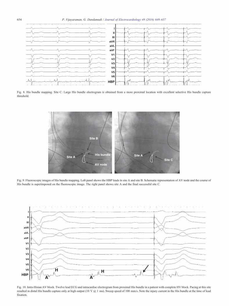
gram and a large His electrogram (site C) with injurycurrent could be achieved (Fig. 8). HBP threshold at thissite was 0.7 V @ 0.5 ms. Minimal or no ventricularcapture at the two distal sites with His bundle capture(sites A and B), suggest that the His bundle was mainly atthe membranous ventricular septum. High capturethreshold at these sites despite adequate fixation atimplant suggest an anatomical variant of His bundlewith early deep penetration towards the left side of theinterventricular septum as previous described in autopsystudies [19]. A more proximal location provided excellentS-HBP in this patient (Fig. 9). Antiarrhythmic therapywith amiodarone was initiated with a plan for DCcardioversion. This case illustrates the value of additionalmapping before accepting high His bundle capturethreshold. If high HBP threshold at sites A and B wereto be accepted, a biventricular pacemaker with anadditional RV or LV lead would have been acceptablebut at the cost of a significantly shorter pacemaker batterylongevity. We prefer a dual chamber pacemaker toachieve longer battery life.
HBP
. 7. His bundle mapping. Site B: By moving the HBP lead to a slightly distal location, nonselective and selective His bundle capture is seen but again only ah output.
Case 3: An 80-year-old man with chronic LBBBpresented with complete heart block and a RBBB escaperhythm at 28 bpm. The patient was urgently brought tothe electrophysiology laboratory for permanent pacemak-er implantation. The atrial lead was placed in the rightventricular apex to provide temporary ventricular pacingduring His bundle mapping. His bundle region wasquickly identified and the electrograms confirmed HVblock. On fixing the lead to this site, large Hiselectrograms with injury current was recorded (Fig. 10).However pacing at 5 V @ 1 ms at this site did not resultin His capture. The HBP lead repositioned slightly moredistally (Figs. 11 and 12) resulted in excellent NS-HBPwith a His capture threshold of 1 V @ 1 ms. Hiselectrogram recorded at this site was much smaller inamplitude and likely represented the far-field signal fromthe proximal His bundle. Near field His electrogram wasnot recorded at this site, as there was no distal conduction.Selective His bundle capture achieved at a low outputwith a short stimulus to ventricular interval of 35 msconfirm that the lead was at the His bundle distal to the
t
HBP
Fig. 8. His bundle mapping. Site C: Large His bundle electrogram is obtained from a more proximal location with excellent selective His bundle capturethreshold.
Site AHis bundle
AV node
Site B
Site CSite A
Fig. 9. Fluoroscopic images of His bundle mapping. Left panel shows the HBP leads in site A and site B. Schematic representation of AV node and the course oHis bundle is superimposed on the fluoroscopic image. The right panel shows site A and the final successful site C.
A
H HA
HBP
Fig. 10. Intra-Hisian AV block. Twelve lead ECG and intracardiac electrogram from proximal His bundle in a patient with complete HV block. Pacing at this siteresulted in distal His bundle capture only at high output (10 V @ 1 ms). Sweep speed of 100 mm/s. Note the injury current in the His bundle at the time of leadfixation.
654 P. Vijayaraman, G. Dandamudi / Journal of Electrocardiology 49 (2016) 649–657
f
AH
AHH H
HBP
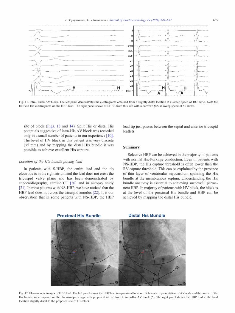
Fig. 11. Intra-Hisian AV block. The left panel demonstrates the electrograms obtained from a slightly distal location at a sweep speed of 100 mm/s. Note thefar-field His electrograms on the HBP lead. The right panel shows NS-HBP from this site with a narrow QRS at sweep speed of 50 mm/s.
FigHisloc
655P. Vijayaraman, G. Dandamudi / Journal of Electrocardiology 49 (2016) 649–657
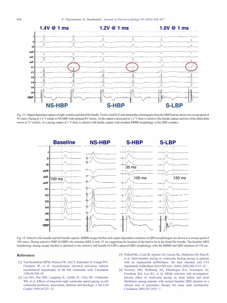
site of block (Figs. 13 and 14). Split His or distal Hispotentials suggestive of intra-His AV block was recordedonly in a small number of patients in our experience [10].The level of HV block in this patient was very discrete(b5 mm) and by mapping the distal His bundle it waspossible to achieve excellent His capture.
Location of the His bundle pacing lead
In patients with S-HBP, the entire lead and the tipelectrode is in the right atrium and the lead does not cross thetricuspid valve plane and has been demonstrated byechocardiography, cardiac CT [20] and in autopsy study[21]. In most patients with NS-HBP, we have noticed that theHBP lead does not cross the tricuspid annulus [22]. It is ourobservation that in some patients with NS-HBP, the HBP
Proximal His Bundle Distal His Bundle
. 12. Fluoroscopic images of HBP lead. The left panel shows the HBP lead in a proximal location. Schematic representation of AV node and the course of thebundle superimposed on the fluoroscopic image with proposed site of discrete intra-His AV block (*). The right panel shows the HBP lead in the finaation slightly distal to the proposed site of His block.
lead tip just passes between the septal and anterior tricuspidleaflets.
Summary
Selective HBP can be achieved in the majority of patientswith normal His-Purkinje conduction. Even in patients withNS-HBP, the His capture threshold is often lower than theRV capture threshold. This can be explained by the presenceof thin layer of ventricular myocardium spanning the Hisbundle at the membranous septum. Understanding the Hisbundle anatomy is essential to achieving successful perma-nent HBP. In majority of patients with HV block, the block isat the level of the proximal His bundle and HBP can beachieved by mapping the distal His bundle.
l
1.4V @ 1 ms 1.2V @ 1 ms 1.0V @ 1 ms
NS-HBP S-HBP S-LBP
HBP
Fig. 13. Output dependent capture of right ventricle and distalHis bundle. Twelve leadECGand intracardiac electrograms from theHBP lead are shownat a sweep speed o50 mm/s. Pacing at 1.4 V results in NS-HBPwith minimal RV fusion. As the output is decreased to 1.2 V there is selective His bundle capture and loss of the initial deltawaves in V1 (circle). At a pacing output of 1 V there is selective left bundle capture with resultant RBBB morphology of the QRS complex.
Baseline NS-HBP S-HBP S-LBP
150 ms 150 ms100 ms
35 ms
HBP
Fig. 14. Selective His bundle and left bundle capture. RBBB escape rhythm and output dependent variations in QRS morphologies are shown at a sweep speed o100 mm/s. During selective HBP (S-HBP), the stimulus-QRS is only 35 ms suggesting the location of the lead to be at the distal His bundle. The baseline QRSmorphology during escape rhythm is identical to the selective left bundle (S-LBP) captured QRS morphology with the RBBB and QRS duration of 150 ms.
656 P. Vijayaraman, G. Dandamudi / Journal of Electrocardiology 49 (2016) 649–657
References
[1] Van Oosterhout MFM, Prinzen FW, Arts T, Schreuder JJ, Vanagt WY,Cleutjens JP, et al. Asynchronous electrical activation inducesasymmetrical hypertrophy of the left ventricular wall. Circulation1998;98:588–95.
[2] Lee MA, Dae MW, Langberg JL, Griffin JC, Chin MC, FinkbeinerWE, et al. Effects of long-term right ventricular apical pacing on leftventricular perfusion, innervation, function and histology. J Am CollCardiol 1994;24:225–32.
f
f
[3] Wilkoff BL, Cook JR, Epstein AE, Greene HL, Hallstrom AP, Hsia H,et al. Dual-chamber pacing or ventricular backup pacing in patientswith an implantable defibrillator: the dual chamber and VVIimplantable defibrillator (DAVID) trial. JAMA 2002;288:3115–23.
[4] Sweeney MO, Hellkamp AS, Ellenbogen KA, Greenspon AJ,Freedman RA, Lee KL, et al. MOde selection trial investigators:adverse effect of ventricular pacing on heart failure and atrialfibrillation among patients with normal baseline QRS duration in aclinical trial of pacemaker therapy for sinus node dysfunction.Circulation 2003;107:2932–7.

657P. Vijayaraman, G. Dandamudi / Journal of Electrocardiology 49 (2016) 649–657
[5] Deshmukh P, Casavant D, Romanyshyn M, Anderson K. Permanentdirect His bundle pacing: a novel approach to cardiac pacing in patientswith normal his-Purkinje activation. Circulation 2000;101:869–77.
[6] Occhetta E, Bortnik M, Magnani A, Francalacci G, Piccinino C,Plebani L, et al. Prevention of ventricular desynchronization bypermanent Para-Hisian pacing after atrioventricular node ablation inchronic atrial fibrillation: a crossover, blinded randomized study versusright ventricular pacing. J Am Coll Cardiol 2006;47:1938–45.
[7] Zanon F, Svetlich C, Occhetta E, Catanzariti D, Cantu F, Padeletti L, etal. Safety and performance of a system specifically designed forselective site pacing. Pacing Clin Electrophysiol 2011;34:339–47.
[8] Sharma P, Dandamudi G, Naperkowski A, Oren JO, Storm RH,Ellenbogen KA, et al. Permanent His bundle pacing is feasible, safeand superior to right ventricular pacing in routine clinical practice.Heart Rhythm 2015;12:305–12.
[9] Vijayaraman P, Dandamudi G, Worsnick SA, Ellenbogen KA. AcuteHis bundle injury current during permanent His bundle pacingpredicts excellent pacing outcomes. Pacin Clin Electrophysiol2015;38:540–6.
[10] Vijayaraman P, Naperkowski A, Ellenbogen KA, Dandamudi G.Permanent His bundle pacing in advanced AV block. Electrophysio-logical insights into site of AV block. JACCCEP 2015;1:571–81.
[11] Kawashima T, Sasaki H. A macroscopic anatomical investigation ofatrioventricular bundle locational variation relative to the membranouspart of the ventricular septum in elderly human hearts. Surg RadiolAnat 2005;27:206–13.
[12] Williams DO, Scherlag B, Hope RR, El-Sherif N, Lazzara R, Samet P.Selective versus nonselective His bundle pacing. Cardiovasc Res1976;10:91–100.
[13] Vijayaraman P, Dandamudi G, Miller J. Paroadoxical cardiac memoryduring permanent His bundle pacing. J Cardiovasc Electrophysiol2014;25:545–6.
[14] El-Sherif N, Amay-Y-Leon F, Schonfield C, Scherlag BJ, Rosen K,Lazzara R, et al. Normalization of bundle branch block patterns by distalHis bundle pacing. Clinical and experimental evidence of longitudinaldissociation in the pathologic His bundle. Circulation 1978;57:473–83.
[15] Vijayaraman P, Ellenbogen KA, Dandamudi G. Longitudinaldissociation in the His bundle: persistent bundle branch block can becorrected by permanent His bundle pacing. Circulation2014;130:A17180 [abstract].
[16] Zanon F, Barold SS. Direct His bundle and paraHisian cardiac pacing.Ann Noninvasive Electrocardiol 2012;17:10–78.
[17] Lustgarten DL, Calame S, Crespo EM, Calame J, Lobel R, Spector PS.Electrical resynchronization induced by direct his-bundle pacing. HeartRhythm 2010;7:15–21.
[18] Occhetta E, Bortnik M, Marino P. Permanent paraHisian pacing.Indian Pacing Electrophysio J 2006;7:110–25.
[19] Massing KG, James TN. Anatomic configuration of the His bundle andbundle branches in the human heart. Circulation 1976;53:609–21.
[20] Vijayaraman P, Dandamudi G, Bauch T, Ellenbogen KA. Imagingevaluation of implantation site of permanent direct His bundle pacinglead. Heart Rhythm 2014;11:529–30.
[21] de Sa C, Hardin NJ, Crespo EM, Nichoas KB, Lustgarten DL. Autopsyevaluation of the implantation site of a permanent direct His bundlepacing lead. Circ Arrhythm Electrophysiol 2012;5:244–6.
[22] Bauch T, Vijayaraman P, Dandamudi G, Ellenbogen KA. Three-dimensional printing for in vivo visualization of His bundle pacingleads. Am J Cardiol 2015;116:485–6.

本文献由“学霸图书馆-文献云下载”收集自网络,仅供学习交流使用。
学霸图书馆(www.xuebalib.com)是一个“整合众多图书馆数据库资源,
提供一站式文献检索和下载服务”的24 小时在线不限IP
图书馆。
图书馆致力于便利、促进学习与科研,提供最强文献下载服务。
图书馆导航:
图书馆首页 文献云下载 图书馆入口 外文数据库大全 疑难文献辅助工具


![RESEARCH Open Access Arthroscopic anatomical …ter-center single bundle ACL reconstruction compared with anatomical double bundle ACL reconstruction [12]. On the other hand, patients](https://img.pdfslide.net/doc/110x75/5f2d57572ad4316fdc54d978/research-open-access-arthroscopic-anatomical-ter-center-single-bundle-acl-reconstruction.jpg)