Embed Size (px)
Citation preview
UNFCCC/CCNUCC CDM � Executive Board ACM0012 / Version 04.0.0 Sectoral Scopes: 01 and 04
EB 58
1/60
Draft revision to the approved consolidated baseline and monitoring methodology ACM0012
�Consolidated baseline methodology for GHG emission reductions from waste energy recovery projects�
I. SOURCES, DEFINITIONS AND APPLICABILITY
Sources
This consolidated baseline and monitoring methodology is based on elements from the following approved methodologies and proposed new methodologies:
• ACM0004: �Consolidated baseline methodology for waste gas and/or heat and/or pressure for power generation� based on:
o NM0031-rev: �OSIL - 10 MW Waste Heat Recovery Based Captive Power Project, India�, whose baseline study, monitoring and verification plan and project design document were prepared by Experts and Consultants of OSIL;
o NM0087: �Baseline methodology for electricity generation using waste heat recovery in sponge iron plants�, prepared by Agrienergy Ltd, Shri Bajrang Power and Ispat Ltd;
o NM0088: �Baseline methodology for electricity production from waste energy recovery in an industrial manufacturing process�, prepared by EcoSecurities B.V. and Groupe Office Cherifien des Phosphates.
• AM0024: �Baseline methodology for greenhouse gas reductions through waste heat recovery and utilization for power generation at cement plants� based on:
o NM0079-rev: �Taishan Huafeng Cement Works Waste Heat Recovery and Utilisation for Power Generation Project, China�, whose baseline study, monitoring and verification plan and Project Design Document were prepared by Westlake Associates Ltd and Natsource Europe Ltd.
• AM0032: �Baseline methodology for waste gas or waste heat based cogeneration system�, based on NM0107-rev methodology �Baseline methodology for waste gas based cogeneration system for power and steam generation� prepared by Alexandria Carbon Black Co.;
• NM0179: �Waste Gas and/or Waste Heat Utilization for �Process Steam� generation or �Process Steam and Power�� prepared by Tata Steel.
The consolidated baseline and monitoring methodology also uses some elements of the following proposed new methodologies:
• NM0155-rev: �Baseline and monitoring methodology for waste gas and/or heat utilisation� prepared by Reliance Industries Limited;
• NM0192-rev: �Baseline and Monitoring Methodology for the recovery and utilization of waste gas in refinery facilities� submitted by EcoSecurities Netherlands B.V. and YPF S.A.
This methodology also refers to the latest approved versions of the following tools:
• �Tool to calculate the emission factor for an electricity system�;
• �Tool for the demonstration and assessment of additionality�;
UNFCCC/CCNUCC CDM � Executive Board ACM0012 / Version 04.0.0 Sectoral Scopes: 01 and 04
EB 58
2/60
• �Tool to determine the baseline efficiency of thermal or electric energy generation systems�;
• �Tool to determine the remaining lifetime of equipment�; and
• �Tool to calculate project or leakage CO2 emissions from fossil fuel combustion�.
For more information regarding the proposals and the tools, as well as their consideration by the Executive Board please refer to <http://cdm.unfccc.int/goto/MPappmeth>.
The selected approach from paragraph 48 of the CDM modalities and procedures
�Existing actual or historical emissions, as applicable�.
or
�Emissions from a technology that represents an economically attractive course of action, taking into account barriers to investment�.
Definitions
For the purpose of this methodology the following definitions apply:
Cogeneration. The simultaneous production of electricity and useful thermal energy from a common fuel source . Element Process. The process of generation of thermal energy through fuel combustion or transfer of heat in a equipment Examples of element processes are steam generation by a boiler and hot air generation by a furnace. Each element process should generate a single output (such as steam or hot air or hot oil). For each element process, energy efficiency is defined as the ratio between the useful energy ( e.g. the enthalpy of the steam multiplied with the steam quantity) and the supplied energy to the element process (the net calorific values of the fuel/s multiplied with the respective fuel quantity).
Recipient facility. The facility that receives useful energy generated using waste energy under the project activity from the waste energy generation facility. It may be the same as the waste energy generation facility.
Reference waste energy generating facility. A reference waste energy generating facility, identified following the guidelines in Annex 1 of this methodology to determine the following for a Greenfield waste energy generation facility: (i) the use of waste energy in absence of CDM project activity, (ii) the extent of the generation of waste energy in the absence of project activity. The identification of the reference facility should not consider facilities implemented as CDM project activities. If no such facility exists in the country, the reference facility should be identified through economic analysis as the most probable situation in the absence of project activity.
Reference energy generation facility. Most plausible facility generating the useful energy that would be used by a Greenfield recipient facility, in the absence of energy available from the proposed CDM project. The reference energy generation facility should be identified through economic analysis (including benchmark (e.g. IRR/NPV) analysis, cost-benefit analysis, or analysis of levelised cost of energy), subject to assessment of availability of such source. The reference energy generation facility should also be demonstrated to be commonly used in the relevant industry sector of the host country.
Unit Process. A process that involves a single transformation of raw materials into products or intermediate materials , as a result of chemical reactions taking place. An example of a unit process is
UNFCCC/CCNUCC CDM � Executive Board ACM0012 / Version 04.0.0 Sectoral Scopes: 01 and 04
EB 58
3/60
catalytic cracking. For the purpose of this methodology, the Unit Process does not include the one with combustion, to separate it from element process.
Waste Energy. Energy contained in a residual stream from industrial processes in the form of heat, chemical energy or pressure., for which it can be demonstrated that it would have been wasted in the absence of the project activity. Examples of waste energy include the energy contained in gases flared or released into the atmosphere, the heat or pressure from a residual stream not recovered (i.e. wasted).
Waste Energy Carrying Medium (WECM). The medium carrying the waste energy in form of heat, chemical energy or pressure. Examples of WECM include gas, air or steam carrying waste energy .
Waste energy generation facility (�the project facility�). The facility where the waste energy , which is to be utilized by the CDM project activity, is available. The project activity can be implemented by the owner of the facility or by a third party (e.g. ESCO). If the waste energy is recovered by a third party in a separate facility, the �project facility� will encompass the both, the waste energy generation facility and the waste energy recovery facility. Applicability
The consolidated methodology is applicable to project activities implemented in an existing or Greenfield facility converting waste energy carried in identified WECM stream(s) into useful energy. The WECM stream may be an energy source for:
• Generation of electricity;
• Cogeneration;
• Direct use as process heat source;
• Generation of heat in element process ;
• Generation of mechanical energy; or
• Supply of heat of reaction with or without process heating. In the absence of the project activity, the WECM stream :
(a) Would not be recovered and therefore would be flared, released to atmosphere, or remain unutilized in the absence of the project activity at the existing or Greenfield project facility; or
(b) Would be partially recovered, and the unrecovered portion of WECM stream would be flared, vented or remained unutilised at the existing or Greenfield project facility.
Project activities improving the WECM recovery may (i) capture and utilise a larger quantity of WECM stream as compared to the historical situation in existing facility, or capture and utilise a larger quantity of WECM stream as compared to a �reference waste energy generating facility�; and/or (ii) apply more energy efficient equipment to replace/ modify/ expand1 waste energy recovery equipment, or implement a more energy efficient equipment than the �reference waste energy generating facility�.
1 The expansion of existing equipment also covers the situation where old equipment is maintained and new capacity
is built up based on additional waste energy captured in the project scenario.
UNFCCC/CCNUCC CDM � Executive Board ACM0012 / Version 04.0.0 Sectoral Scopes: 01 and 04
EB 58
4/60
The methodology is applicable under the following conditions:
• For project activities which recover waste pressure, the methodology is applicable where waste pressure is used to generate electricity only and the electricity generated from waste pressure is measurable;
• Regulations do not require the project facility to recover and/or utilize the waste energy prior to the implementation of the project activity;
• The methodology is applicable to both Greenfield and existing waste energy generation facilities. If the production capacity of the project facility is expanded as a result of the project activity, the added production capacity must be treated as a Greenfield facility;2
• Waste energy that is released under abnormal operation (for example, emergencies, shut down) of the project facility shall not be included in the emission reduction calculations.
If multiple waste gas streams are available in the project facility and can be used interchangeably for various applications as part of the energy sources in the facility, the recovery of any waste gas stream, which would be totally or partially recovered in the absence of the project activity, shall not be reduced due to the implementation of CDM project activity. For such situations, the guidance provided in Annex 3 shall be followed.
The methodology is not applicable to the cases where a WECM stream is partially recovered in the absence of the CDM project activity to supply the heat of reaction, and the recovery of this WECM stream is increased under the project activity to replace fossil fuels used for the purpose of supplying heat of reaction.
This methodology is also not applicable to project activities where the waste gas/heat recovery project is implemented in a single-cycle power plant (e.g. gas turbine or diesel generator) to generate power.3 However, the projects recovering waste energy from single cycle and/or combined cycle power plants for the purpose of generation of heat only can apply this methodology.
The emission reduction credits can be claimed up to the end of the lifetime of the waste energy generation equipment. The remaining lifetime of the equipment should be determined using the latest version of the �Tool to determine the remaining lifetime of equipment�.
The extent of use of waste energy from the waste energy generation facilities in the absence of the CDM project activity will be determined in accordance with the procedures provided in Annex 1 (for Greenfield project facilities) and in Annex 2 (for existing project facilities) to this methodology.
In addition, the applicability conditions included in the tools referred to above apply.
Project Boundary
The geographical extent project boundary shall include the relevant WECM stream(s), equipment and energy distribution system in the following facilities:
(1) The �project facility�;
(2) The �recipient facility(ies)�, which may be the same as the �project facility�.
2 See the section on identification of baseline scenario for the guidance on added capacity and Greenfield facilities. 3 Project proponents can consider approved consolidated methodology ACM0007 for such project activities.
UNFCCC/CCNUCC CDM � Executive Board ACM0012 / Version 04.0.0 Sectoral Scopes: 01 and 04
EB 58
5/60
The spatial extent of the grid is as defined in the �Tool to calculate the emission factor for an electricity system�. The relevant equipment and energy distribution system cover:
• In project facility, the WECM stream(s), waste energy recovery and useful energy generation equipment, and distribution system(s) for useful project energy;
• In recipient facility, the equipment which receive useful energy supplied by the project, and distribution system(s) for useful project energy.
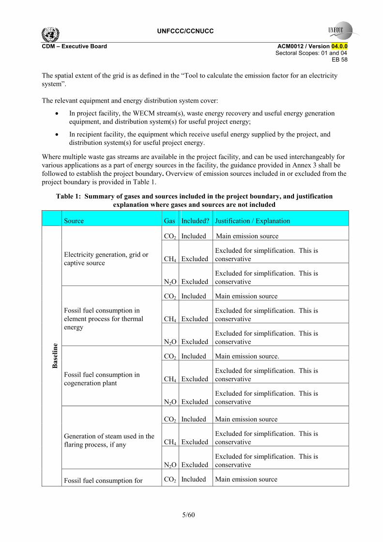
Where multiple waste gas streams are available in the project facility, and can be used interchangeably for various applications as a part of energy sources in the facility, the guidance provided in Annex 3 shall be followed to establish the project boundary. Overview of emission sources included in or excluded from the project boundary is provided in Table 1.
Table 1: Summary of gases and sources included in the project boundary, and justification explanation where gases and sources are not included
Source Gas Included? Justification / Explanation
CO2 Included Main emission source
CH4 Excluded Excluded for simplification. This is conservative Electricity generation, grid or
captive source
N2O Excluded Excluded for simplification. This is conservative
CO2 Included Main emission source
CH4 Excluded Excluded for simplification. This is conservative
Fossil fuel consumption in element process for thermal energy
N2O Excluded Excluded for simplification. This is conservative
CO2 Included Main emission source.
CH4 Excluded Excluded for simplification. This is conservative Fossil fuel consumption in
cogeneration plant
N2O Excluded Excluded for simplification. This is conservative
CO2 Included Main emission source
CH4 Excluded Excluded for simplification. This is conservative
Generation of steam used in the flaring process, if any
N2O Excluded Excluded for simplification. This is conservative
Bas
elin
e
Fossil fuel consumption for CO2 Included Main emission source
UNFCCC/CCNUCC CDM � Executive Board ACM0012 / Version 04.0.0 Sectoral Scopes: 01 and 04
EB 58
6/60
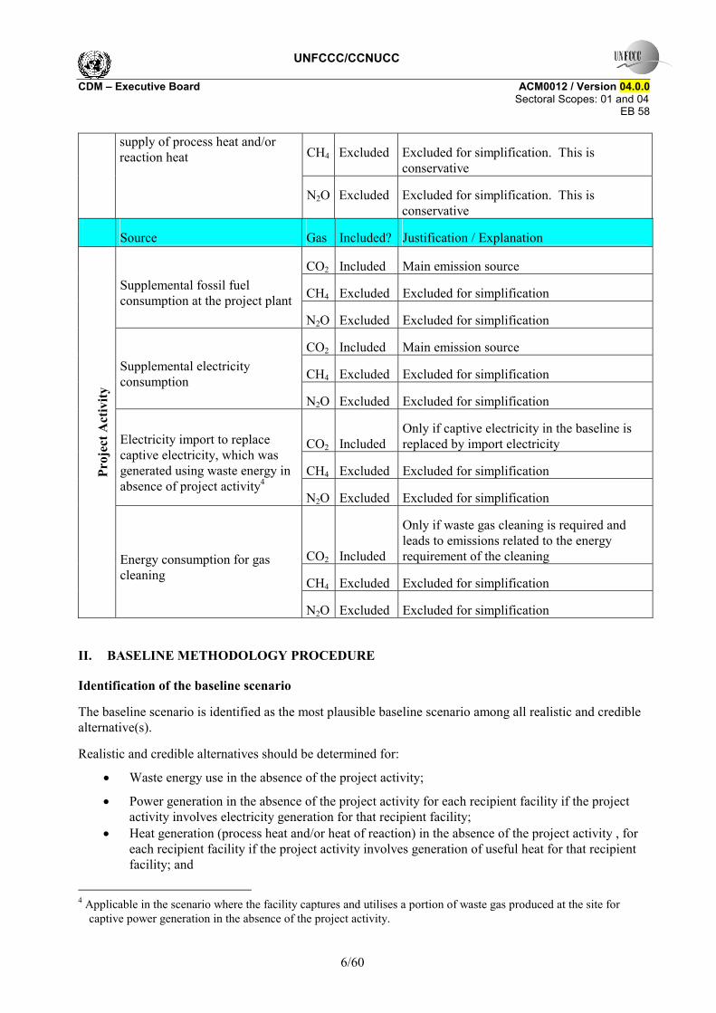
CH4 Excluded Excluded for simplification. This is conservative
supply of process heat and/or reaction heat
N2O Excluded Excluded for simplification. This is conservative
Source Gas Included? Justification / Explanation
CO2 Included Main emission source
CH4 Excluded Excluded for simplification Supplemental fossil fuel consumption at the project plant
N2O Excluded Excluded for simplification
CO2 Included Main emission source
CH4 Excluded Excluded for simplification Supplemental electricity consumption
N2O Excluded Excluded for simplification
CO2 Included Only if captive electricity in the baseline is replaced by import electricity
CH4 Excluded Excluded for simplification
Electricity import to replace captive electricity, which was generated using waste energy in absence of project activity4
N2O Excluded Excluded for simplification
CO2 Included
Only if waste gas cleaning is required and leads to emissions related to the energy requirement of the cleaning
CH4 Excluded Excluded for simplification
Proj
ect A
ctiv
ity
Energy consumption for gas cleaning
N2O Excluded Excluded for simplification
II. BASELINE METHODOLOGY PROCEDURE
Identification of the baseline scenario
The baseline scenario is identified as the most plausible baseline scenario among all realistic and credible alternative(s).
Realistic and credible alternatives should be determined for:
• Waste energy use in the absence of the project activity;
• Power generation in the absence of the project activity for each recipient facility if the project activity involves electricity generation for that recipient facility;
• Heat generation (process heat and/or heat of reaction) in the absence of the project activity , for each recipient facility if the project activity involves generation of useful heat for that recipient facility; and
4 Applicable in the scenario where the facility captures and utilises a portion of waste gas produced at the site for
captive power generation in the absence of the project activity.
UNFCCC/CCNUCC CDM � Executive Board ACM0012 / Version 04.0.0 Sectoral Scopes: 01 and 04
EB 58
7/60
• Mechanical energy generation in the absence of the project activity, for each recipient facility if the project activity involves generation of useful mechanical energy for that recipient facility.
The information on the utilization of heat, electricity and/or mechanical energy in the absence of the CDM project activity will be sourced from the recipient facility(ies); and the information on the utilization of the waste energy in the absence of the CDM project activity will be sourced from the project facility. Hence, the CDM project proponent shall determine baseline options, identify the most appropriate baseline scenario, determine the baseline fuel and demonstrate and assess additionality in consultation with the recipient facility(ies) and the project facility. For this purpose, the project facility and the recipient facility(ies) shall be identified when preparing the PDD.
Multiple components generating different types of energy in the project activity scenario
Determine the heat, power or mechanical energy requirement of the recipient facility(ies) in the project boundary that will be met by one or more components of the project activity. In determining the baseline scenario, project participants shall identify the realistic and credible alternatives to the project activity that would provide an output equivalent to the combined output of all the components of the project activity. These alternatives may comprise of one or more component(s). Therefore any alternative, identified for the project activity should provide the same amount of heat, power or mechanical energy that is provided by the project activity and should include the alternate use/s of the waste energy that is recovered by the project activity. These alternatives shall be determined as realistic combinations of the following options (identified in step 1).
The project participant shall exclude baseline options that:
• Do not comply with legal and regulatory requirements; or
• Involve fuels (used for the generation of heat, power or mechanical energy), that are not available in the host country.
The project participant shall provide evidence and supporting documents to exclude baseline options that meet the above-mentioned criteria.
Step 1: Define the most plausible baseline scenario for the generation of heat , electricity and mechanical energy using the following baseline options and combinations
The baseline candidates should be considered for the following facilities:
• For the waste energy generation facility(ies) where the waste energy is generated; and
• For the recipient facility(ies) where the energy is consumed.
As the project activity can be implemented on waste energy generated in an existing or a Greenfield project facility, the following combinations, which represent the baseline scenarios of an existing facility, should be tailored for Greenfield facilities. Therefore, for the Greenfield project facilities, the following baseline scenarios should be analysed based upon the guidelines included in Annex 1. At an existing project facility, if the production capacity is increased after the implementation of the project activitites, the scenarios for added capacity may be different from those identified for the capacity which displaces historical consumption of heat or power. The approach for baseline scenarios for added production capacity should be same as that followed for the Greenfield facility.
For the use of waste energy, the realistic and credible alternative(s) may include, inter alia:
W1: WECM is directly vented to atmosphere without incineration;
UNFCCC/CCNUCC CDM � Executive Board ACM0012 / Version 04.0.0 Sectoral Scopes: 01 and 04
EB 58
8/60
W2: WECM is released to the atmosphere (for example after incineration) or waste heat is released (or vented) to the atmosphere or waste pressure energy is not utilized;
W3: Waste energy is sold as an energy source;
W4 Waste energy is used for meeting energy demand at the recipient facility(ies);
W5: A portion of the quantity or energy of WECM is recovered for generation of heat and/ or electricity and/or mechanical energy, while the rest of the waste energy produced at the project facility is flared/released to atmosphere/ unutilised;5
W6: All the waste energy produced at the facility is captured and used for export electricity generation or steam.
For power generation, the realistic and credible alternative(s) may include, inter alia:
P1: Proposed project activity not undertaken as a CDM project activity;
P2: On-site or off-site existing fossil fuel fired cogeneration plant;6
P3: On-site or off-site Greenfield fossil fuel fired cogeneration plant;7
P4: On-site or off-site existing renewable energy based cogeneration plant;8
P5: On-site or off-site Greenfield renewable energy based cogeneration plant;9
P6: On-site or off-site existing fossil fuel based existing identified captive power plant;
P7: On-site or off-site existing identified renewable energy or other waste energy based captive power plant;
P8: On-site or off-site Greenfield fossil fuel based captive plant;
P9: On-site or off-site Greenfield renewable energy or other waste energy based captive plant;
P10: Sourced from grid-connected power plants;
P11: Existing captive electricity generation using waste energy (if project activity is captive generation using waste energy, this scenario represents captive generation with lower efficiency or lower recovery than the project activity);
P12: Existing cogeneration using waste energy, but at a lower efficiency or lower recovery.
For heat generation, realistic and credible alternative(s) may include, inter alia:
H1: Proposed project activity is not undertaken as a CDM project activity;
H2: On-site or off-site existing fossil fuel based cogeneration plant;
H3: On-site or off-site Greenfield fossil fuel based cogeneration plant;
H4: On-site or off-site existing renewable energy based cogeneration plant;
H5: On-site or off-site Greenfield renewable energy based cogeneration plant;
H6: An existing fossil fuel based element process;
5 As per the applicability condition the methodology is not applicable for projects for supply of heat of reaction,
having partial recovery in the baseline. 6 Scenarios P2 and H2 are related to the same existing fossil fuel cogeneration plant. 7 Scenarios P3 and H3 are related to the same Greenfield fossil fuel cogeneration plant. 8 Scenarios P4 and H4 are related to the same existing renewable energy based cogeneration plant. 9 Scenarios P5 and H5 are related to the same Greenfield renewable energy based cogeneration plant.
UNFCCC/CCNUCC CDM � Executive Board ACM0012 / Version 04.0.0 Sectoral Scopes: 01 and 04
EB 58
9/60
H7: A new fossil fuel based element process;
H8: An existing renewable energy or other waste energy based element process to supply heat ;
H9: A new renewable energy or other waste energy based element process to supply heat ;
H10: Any other source such as district heat;
H11: Other heat generation technologies (e.g. heat pumps or solar energy);
H12: Steam/Process heat generation from waste energy, but with lower efficiency or lower recovery;
H13: Cogeneration with waste energy, but at a lower efficiency or lower recovery;
H14: On site fossil fuel consumption to supply heat.
For mechanical energy, realistic and credible alternatives may include, inter alia:
M1: The proposed project activity is not undertaken as a CDM project activity;
M2: Steam produced by existing fossil fuel based boilers driving mechanical turbines;
M3: Steam produced by new fossil fuel based boilers driving mechanical turbines;
M4: Steam produced by existing renewable energy or other waste energy10 based boilers driving mechanical turbines;
M5: Steam produced by new renewable energy or other waste energy11 based boilers driving mechanical turbines;
M6: Waste gas pressure based mechanical energy generation;
M7: Existing electrical motors are used as motive power to generate mechanical energy.
M8: New electrical motors are used as motive power to generate mechanical energy.
Step 2: Step 2 and/or Step 3 of the latest approved version of the �Tool for the demonstration and assessment of additionality� shall be used to identify the most plausible baseline scenarios by eliminating non-feasible options (e.g. alternatives where barriers are prohibitive or which are clearly economically unattractive).
The project proponents are required to use economic analysis for the identification of the baseline scenario for the following three situations.
(1) Where, for an existing project facility, the WECM utilised by the project activity was totally or partially recovered in the absence of the CDM project activity.
(2) Where the CDM waste energy recovery project is implemented in a Greenfield project facility. The investment analysis for the Greenfield projects include the cost of the fuel that would have been used by the recipient facility(ies) in the absence of the CDM project. The fuels for such analysis should include all the fuels available in the host country, including those, which can be imported in the host country.
(3) Where the CDM waste energy recovery project is implemented in an existing facility to supply the useful energy generated to a Greenfield recipient, and therefore the likely baseline scenario is based on a �reference energy generation facility�. The energy generation for such a reference facility, including the fuel (either available in host country or imported without any supply constraint), should be determined based on the investment analysis.
UNFCCC/CCNUCC CDM � Executive Board ACM0012 / Version 04.0.0 Sectoral Scopes: 01 and 04
EB 58
10/60
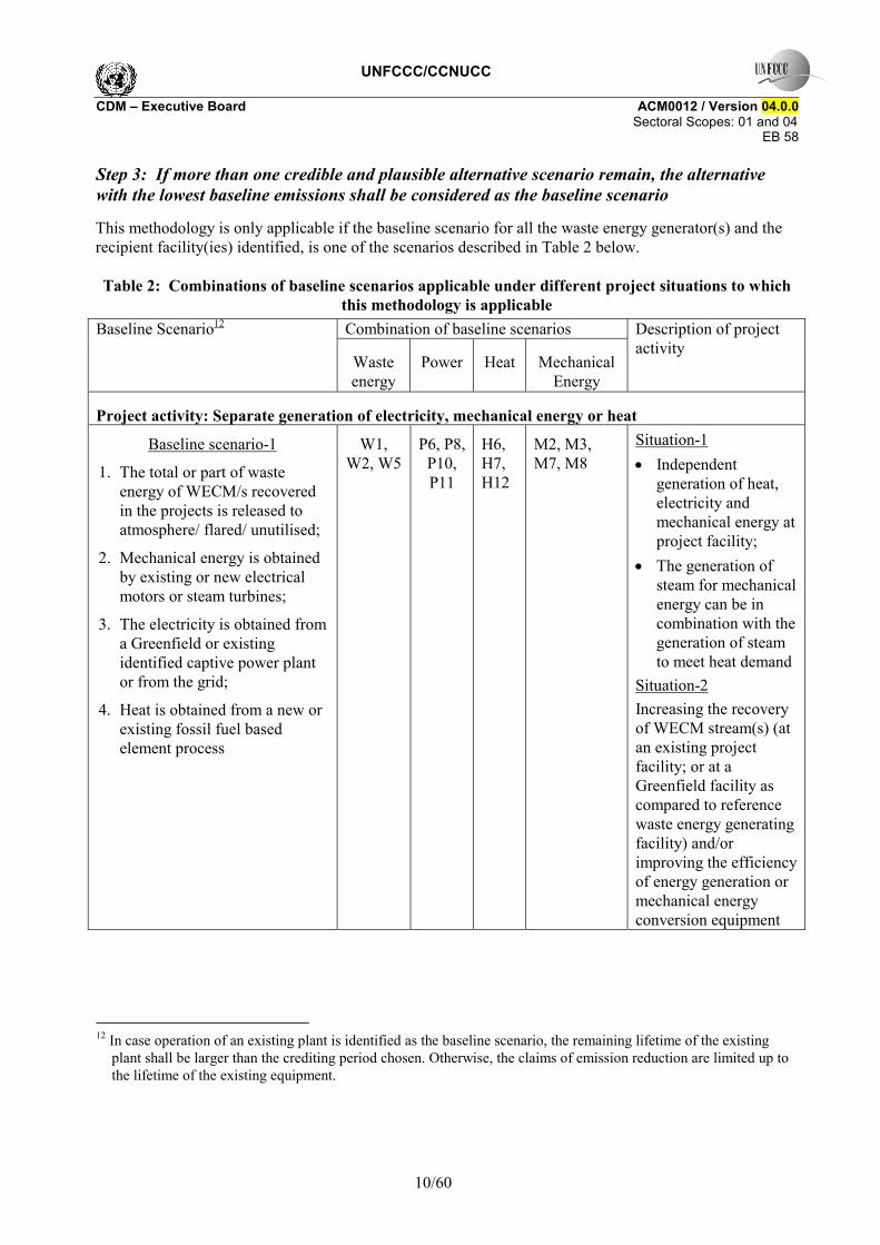
Step 3: If more than one credible and plausible alternative scenario remain, the alternative with the lowest baseline emissions shall be considered as the baseline scenario
This methodology is only applicable if the baseline scenario for all the waste energy generator(s) and the recipient facility(ies) identified, is one of the scenarios described in Table 2 below. Table 2: Combinations of baseline scenarios applicable under different project situations to which
this methodology is applicable Combination of baseline scenarios Baseline Scenario12
Waste energy
Power Heat Mechanical Energy
Description of project activity
Project activity: Separate generation of electricity, mechanical energy or heat
Baseline scenario-1
1. The total or part of waste energy of WECM/s recovered in the projects is released to atmosphere/ flared/ unutilised;
2. Mechanical energy is obtained by existing or new electrical motors or steam turbines;
3. The electricity is obtained from a Greenfield or existing identified captive power plant or from the grid;
4. Heat is obtained from a new or existing fossil fuel based element process
W1, W2, W5
P6, P8, P10, P11
H6, H7, H12
M2, M3, M7, M8
Situation-1 • Independent
generation of heat, electricity and mechanical energy at project facility;
• The generation of steam for mechanical energy can be in combination with the generation of steam to meet heat demand
Situation-2 Increasing the recovery of WECM stream(s) (at an existing project facility; or at a Greenfield facility as compared to reference waste energy generating facility) and/or improving the efficiency of energy generation or mechanical energy conversion equipment
12 In case operation of an existing plant is identified as the baseline scenario, the remaining lifetime of the existing
plant shall be larger than the crediting period chosen. Otherwise, the claims of emission reduction are limited up to the lifetime of the existing equipment.
UNFCCC/CCNUCC CDM � Executive Board ACM0012 / Version 04.0.0 Sectoral Scopes: 01 and 04
EB 58
11/60
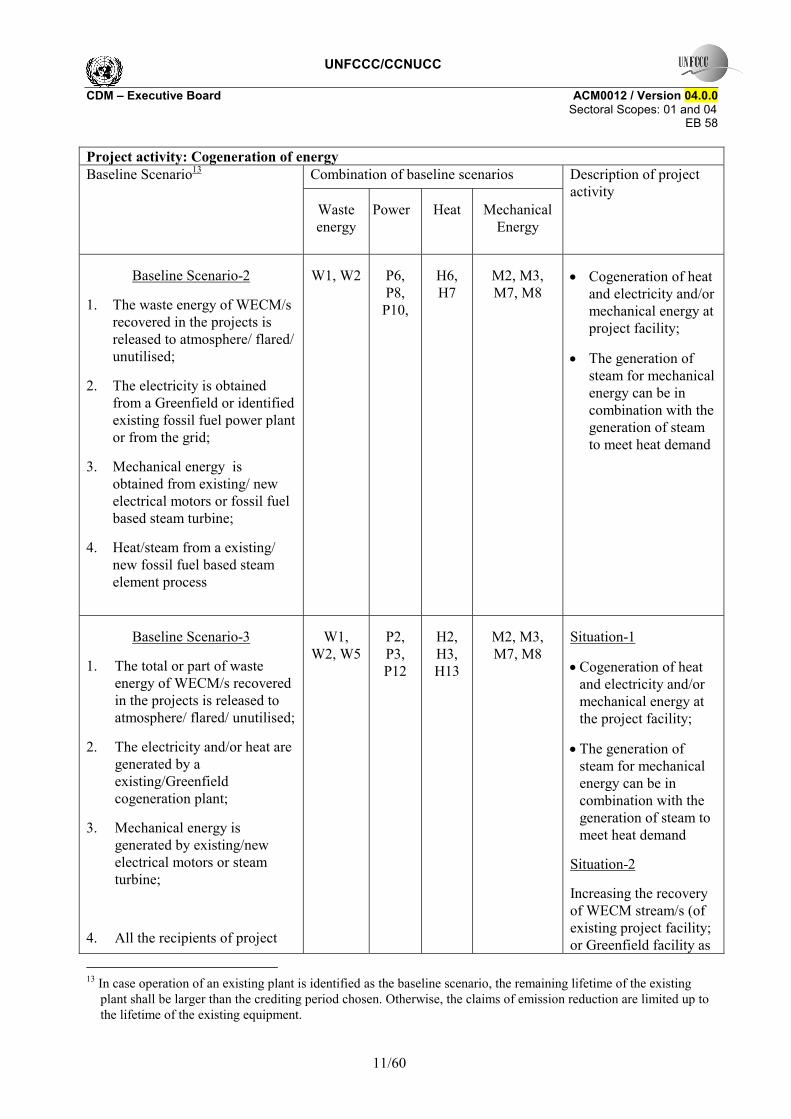
Project activity: Cogeneration of energy Combination of baseline scenarios Baseline Scenario13
Waste energy
Power Heat
Mechanical Energy
Description of project activity
Baseline Scenario-2
1. The waste energy of WECM/s recovered in the projects is released to atmosphere/ flared/ unutilised;
2. The electricity is obtained from a Greenfield or identified existing fossil fuel power plant or from the grid;
3. Mechanical energy is obtained from existing/ new electrical motors or fossil fuel based steam turbine;
4. Heat/steam from a existing/ new fossil fuel based steam element process
W1, W2 P6, P8,
P10,
H6, H7
M2, M3, M7, M8
• Cogeneration of heat and electricity and/or mechanical energy at project facility;
• The generation of steam for mechanical energy can be in combination with the generation of steam to meet heat demand
Baseline Scenario-3
1. The total or part of waste energy of WECM/s recovered in the projects is released to atmosphere/ flared/ unutilised;
2. The electricity and/or heat are generated by a existing/Greenfield cogeneration plant;
3. Mechanical energy is generated by existing/new electrical motors or steam turbine;
4. All the recipients of project
W1, W2, W5
P2, P3, P12
H2, H3, H13
M2, M3, M7, M8
Situation-1
• Cogeneration of heat and electricity and/or mechanical energy at the project facility;
• The generation of steam for mechanical energy can be in combination with the generation of steam to meet heat demand
Situation-2
Increasing the recovery of WECM stream/s (of existing project facility; or Greenfield facility as
13 In case operation of an existing plant is identified as the baseline scenario, the remaining lifetime of the existing
plant shall be larger than the crediting period chosen. Otherwise, the claims of emission reduction are limited up to the lifetime of the existing equipment.
UNFCCC/CCNUCC CDM � Executive Board ACM0012 / Version 04.0.0 Sectoral Scopes: 01 and 04
EB 58
12/60
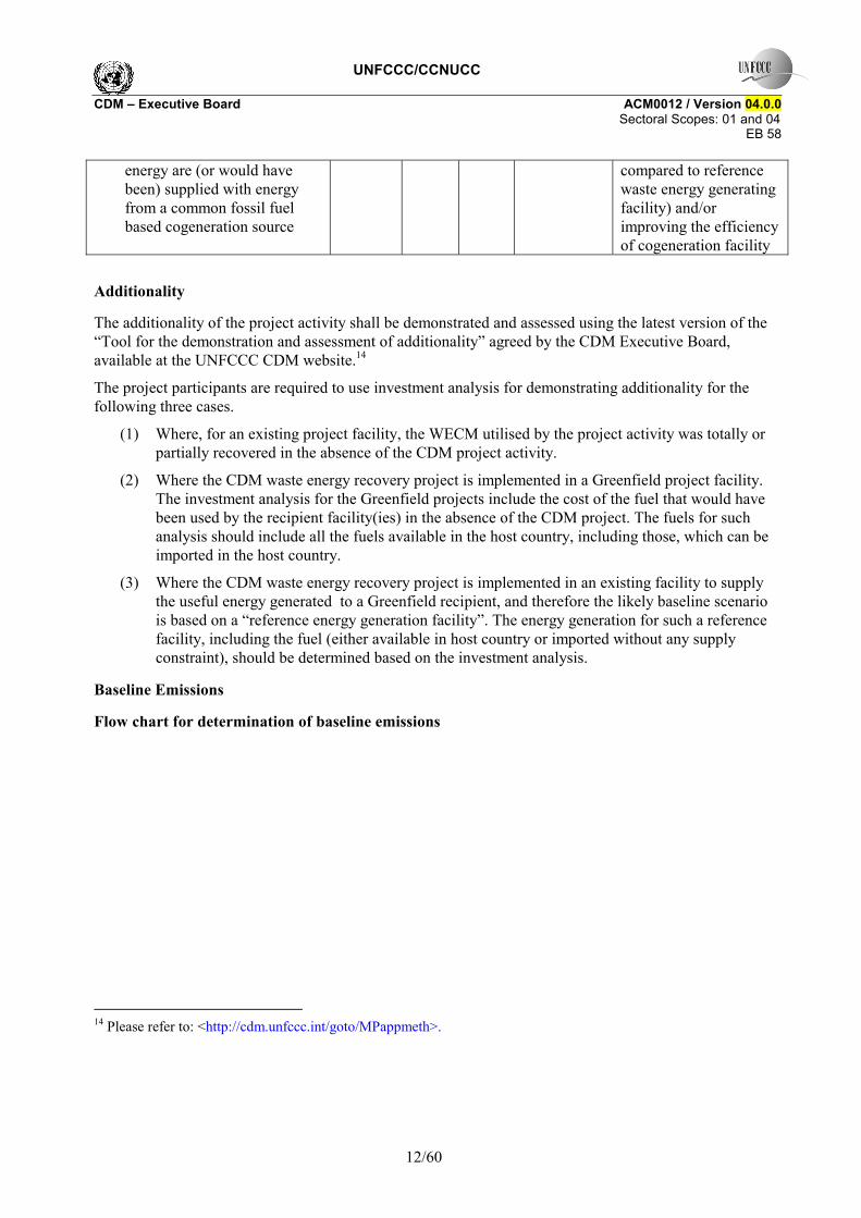
energy are (or would have been) supplied with energy from a common fossil fuel based cogeneration source
compared to reference waste energy generating facility) and/or improving the efficiency of cogeneration facility
Additionality
The additionality of the project activity shall be demonstrated and assessed using the latest version of the �Tool for the demonstration and assessment of additionality� agreed by the CDM Executive Board, available at the UNFCCC CDM website.14
The project participants are required to use investment analysis for demonstrating additionality for the following three cases.
(1) Where, for an existing project facility, the WECM utilised by the project activity was totally or partially recovered in the absence of the CDM project activity.
(2) Where the CDM waste energy recovery project is implemented in a Greenfield project facility. The investment analysis for the Greenfield projects include the cost of the fuel that would have been used by the recipient facility(ies) in the absence of the CDM project. The fuels for such analysis should include all the fuels available in the host country, including those, which can be imported in the host country.
(3) Where the CDM waste energy recovery project is implemented in an existing facility to supply the useful energy generated to a Greenfield recipient, and therefore the likely baseline scenario is based on a �reference energy generation facility�. The energy generation for such a reference facility, including the fuel (either available in host country or imported without any supply constraint), should be determined based on the investment analysis.
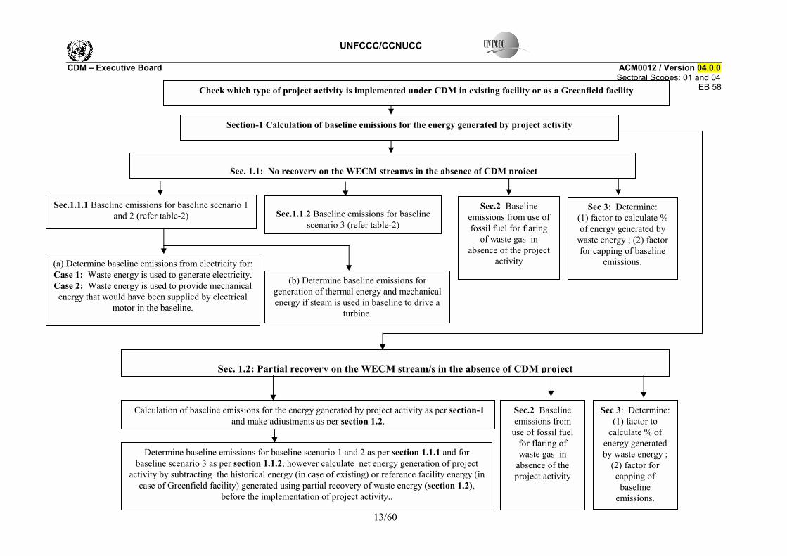
Baseline Emissions
Flow chart for determination of baseline emissions
14 Please refer to: <http://cdm.unfccc.int/goto/MPappmeth>.
UNFCCC/CCNUCC CDM � Executive Board ACM0012 / Version 04.0.0
Sectoral Scopes: 01 and 04 EB 58
13/60
Check which type of project activity is implemented under CDM in existing facility or as a Greenfield facility
Sec.1.1.1 Baseline emissions for baseline scenario 1 and 2 (refer table-2)
(a) Determine baseline emissions from electricity for: Case 1: Waste energy is used to generate electricity. Case 2: Waste energy is used to provide mechanical energy that would have been supplied by electrical
motor in the baseline.
Sec. 1.1: No recovery on the WECM stream/s in the absence of CDM project
(b) Determine baseline emissions for generation of thermal energy and mechanical energy if steam is used in baseline to drive a
turbine.
Sec.1.1.2 Baseline emissions for baseline scenario 3 (refer table-2)
Sec 3: Determine: (1) factor to calculate % of energy generated by
waste energy ; (2) factor for capping of baseline
emissions.
Sec.2 Baseline emissions from use of fossil fuel for flaring
of waste gas in absence of the project
activity
Section-1 Calculation of baseline emissions for the energy generated by project activity
Sec. 1.2: Partial recovery on the WECM stream/s in the absence of CDM project
Determine baseline emissions for baseline scenario 1 and 2 as per section 1.1.1 and for baseline scenario 3 as per section 1.1.2, however calculate net energy generation of project
activity by subtracting the historical energy (in case of existing) or reference facility energy (in case of Greenfield facility) generated using partial recovery of waste energy (section 1.2),
before the implementation of project activity..
Calculation of baseline emissions for the energy generated by project activity as per section-1 and make adjustments as per section 1.2.
Sec 3: Determine: (1) factor to
calculate % of energy generated by waste energy ;
(2) factor for capping of baseline
emissions.
Sec.2 Baseline emissions from
use of fossil fuel for flaring of waste gas in
absence of the project activity
UNFCCC/CCNUCC CDM � Executive Board ACM0012 / Version 04.0.0 Sectoral Scopes: 01 and 04
EB 58
14/60
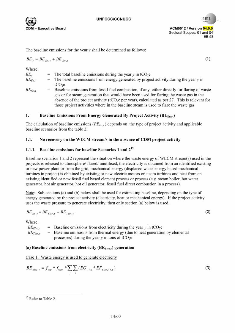
The baseline emissions for the year y shall be determined as follows:
yflstyEny BEBEBE ,, += (1)
Where: BEy = The total baseline emissions during the year y in tCO2e BEEn,y = The baseline emissions from energy generated by project activity during the year y in
tCO2e BEflst,y = Baseline emissions from fossil fuel combustion, if any, either directly for flaring of waste
gas or for steam generation that would have been used for flaring the waste gas in the absence of the project activity (tCO2e per year), calculated as per 27. This is relevant for those project activities where in the baseline steam is used to flare the waste gas
1. Baseline Emissions From Energy Generated By Project Activity (BEEn,y )
The calculation of baseline emissions (BEEn,y ) depends on the type of project activity and applicable baseline scenarios from the table 2. 1.1. No recovery on the WECM stream/s in the absence of CDM project activity
1.1.1. Baseline emissions for baseline Scenarios 1 and 215
Baseline scenarios 1 and 2 represent the situation where the waste energy of WECM stream(s) used in the projects is released to atmosphere/ flared/ unutilised, the electricity is obtained from an identified existing or new power plant or from the grid, mechanical energy (displaced waste energy based mechanical turbines in project) is obtained by existing or new electric motors or steam turbines and heat from an existing identified or new fossil fuel based element process or process (e.g. steam boiler, hot water generator, hot air generator, hot oil generator, fossil fuel direct combustion in a process).
Note: Sub-sections (a) and (b) below shall be used for estimating baseline, depending on the type of energy generated by the project activity (electricity, heat or mechanical energy). If the project activity uses the waste pressure to generate electricity, then only section (a) below is used.
yTheryElecyEn BEBEBE ,,, += (2)
Where: BEElec,y = Baseline emissions from electricity during the year y in tCO2e BETher,y = Baseline emissions from thermal energy (due to heat generation by elemental
processes) during the year y in tons of tCO2e
(a) Baseline emissions from electricity (BEElec,y) generation
Case 1: Waste energy is used to generate electricity
∑∑=j i
yjiElecyjiwcmcapyElec EFEGffBE )*(** ,,,,,, (3)
15 Refer to Table 2.
UNFCCC/CCNUCC CDM � Executive Board ACM0012 / Version 04.0.0 Sectoral Scopes: 01 and 04
EB 58
15/60
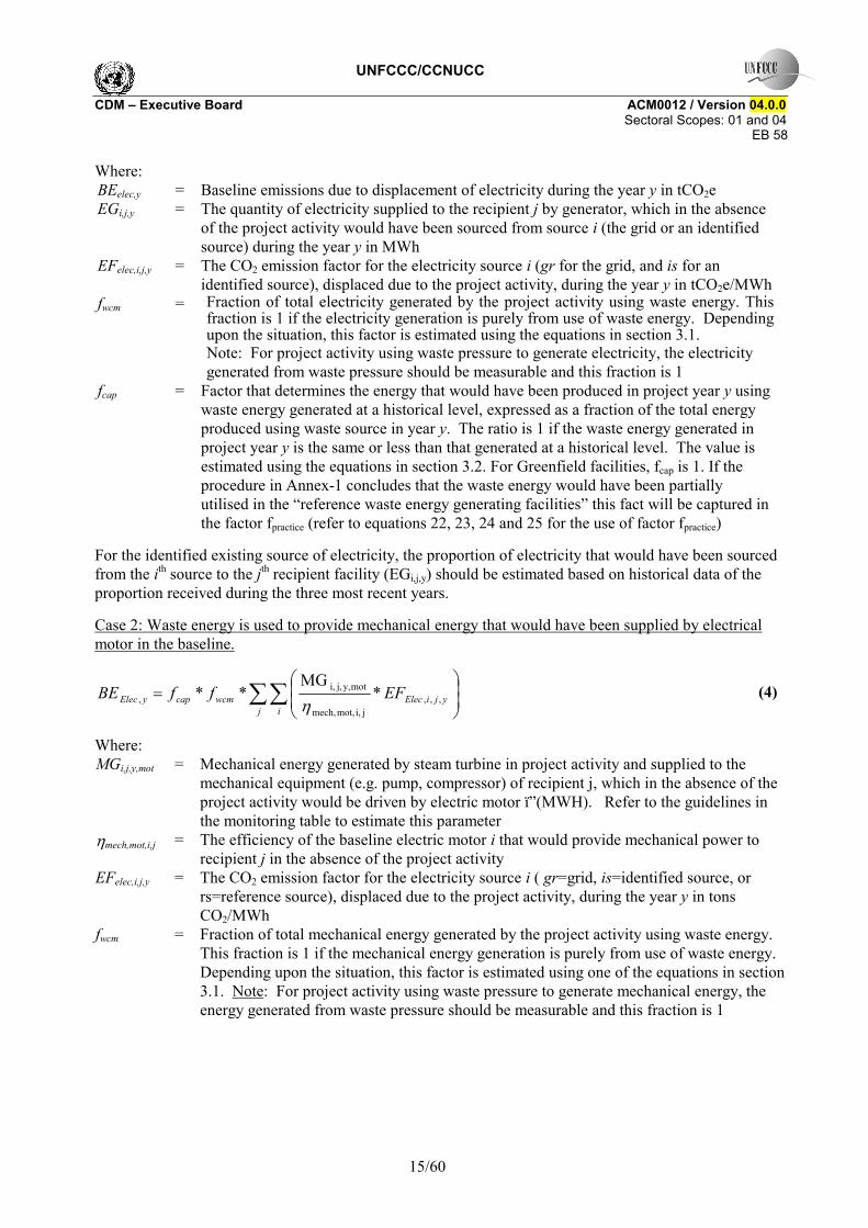
Where: BEelec,y = Baseline emissions due to displacement of electricity during the year y in tCO2e EGi,j,y = The quantity of electricity supplied to the recipient j by generator, which in the absence
of the project activity would have been sourced from source i (the grid or an identified source) during the year y in MWh
EFelec,i,j,y = The CO2 emission factor for the electricity source i (gr for the grid, and is for an identified source), displaced due to the project activity, during the year y in tCO2e/MWh
fwcm = Fraction of total electricity generated by the project activity using waste energy. This fraction is 1 if the electricity generation is purely from use of waste energy. Depending upon the situation, this factor is estimated using the equations in section 3.1. Note: For project activity using waste pressure to generate electricity, the electricity generated from waste pressure should be measurable and this fraction is 1
fcap = Factor that determines the energy that would have been produced in project year y using waste energy generated at a historical level, expressed as a fraction of the total energy produced using waste source in year y. The ratio is 1 if the waste energy generated in project year y is the same or less than that generated at a historical level. The value is estimated using the equations in section 3.2. For Greenfield facilities, fcap is 1. If the procedure in Annex-1 concludes that the waste energy would have been partially utilised in the �reference waste energy generating facilities� this fact will be captured in the factor fpractice (refer to equations 22, 23, 24 and 25 for the use of factor fpractice)
For the identified existing source of electricity, the proportion of electricity that would have been sourced from the ith source to the jth recipient facility (EGi,j,y) should be estimated based on historical data of the proportion received during the three most recent years.
Case 2: Waste energy is used to provide mechanical energy that would have been supplied by electrical motor in the baseline.
∑∑ ⎟⎟⎠
⎞⎜⎜⎝
⎛=
j iyjiElecwcmcapyElec EFffBE ,,,
ji,mot,mech,
moty,j,i,, *
MG**
η (4)
Where: MGi,j,y,mot = Mechanical energy generated by steam turbine in project activity and supplied to the
mechanical equipment (e.g. pump, compressor) of recipient j, which in the absence of the project activity would be driven by electric motor ï�(MWH). Refer to the guidelines in the monitoring table to estimate this parameter
ηmech,mot,i,j = The efficiency of the baseline electric motor i that would provide mechanical power to recipient j in the absence of the project activity
EFelec,i,j,y = The CO2 emission factor for the electricity source i ( gr=grid, is=identified source, or rs=reference source), displaced due to the project activity, during the year y in tons CO2/MWh
fwcm = Fraction of total mechanical energy generated by the project activity using waste energy. This fraction is 1 if the mechanical energy generation is purely from use of waste energy. Depending upon the situation, this factor is estimated using one of the equations in section 3.1. Note: For project activity using waste pressure to generate mechanical energy, the energy generated from waste pressure should be measurable and this fraction is 1
UNFCCC/CCNUCC CDM � Executive Board ACM0012 / Version 04.0.0 Sectoral Scopes: 01 and 04
EB 58
16/60
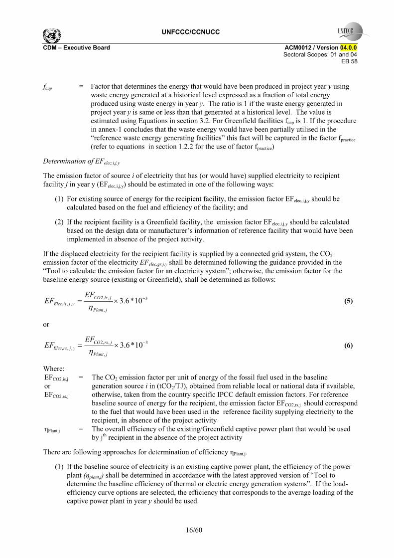
fcap = Factor that determines the energy that would have been produced in project year y using
waste energy generated at a historical level expressed as a fraction of total energy produced using waste energy in year y. The ratio is 1 if the waste energy generated in project year y is same or less than that generated at a historical level. The value is estimated using Equations in section 3.2. For Greenfield facilities fcap is 1. If the procedure in annex-1 concludes that the waste energy would have been partially utilised in the �reference waste energy generating facilities� this fact will be captured in the factor fpractice (refer to equations in section 1.2.2 for the use of factor fpractice)
Determination of EFelec,i,j,y
The emission factor of source i of electricity that has (or would have) supplied electricity to recipient facility j in year y (EFelec,i,j,y) should be estimated in one of the following ways:
(1) For existing source of energy for the recipient facility, the emission factor EFelec,i,j,y should be calculated based on the fuel and efficiency of the facility; and
(2) If the recipient facility is a Greenfield facility, the emission factor EFelec,i,j,y should be calculated based on the design data or manufacturer�s information of reference facility that would have been implemented in absence of the project activity.
If the displaced electricity for the recipient facility is supplied by a connected grid system, the CO2 emission factor of the electricity EFelec,gr,j,y shall be determined following the guidance provided in the �Tool to calculate the emission factor for an electricity system�; otherwise, the emission factor for the baseline energy source (existing or Greenfield), shall be determined as follows:
3
,
,,2,,, 10*6.3 −×=
jPlant
jisCOyjisElec
EFEF
η (5)
or
3
,
,,2,,, 10*6.3 −×=
jPlant
jrsCOyjrsElec
EFEF
η (6)
Where: EFCO2,is,j or EFCO2,rs,j
= The CO2 emission factor per unit of energy of the fossil fuel used in the baseline generation source i in (tCO2/TJ), obtained from reliable local or national data if available, otherwise, taken from the country specific IPCC default emission factors. For reference baseline source of energy for the recipient, the emission factor EFCO2,rs,j should correspond to the fuel that would have been used in the reference facility supplying electricity to the recipient, in absence of the project activity
ηPlant,j = The overall efficiency of the existing/Greenfield captive power plant that would be used by jth recipient in the absence of the project activity
There are following approaches for determination of efficiency ηPlant,j.
(1) If the baseline source of electricity is an existing captive power plant, the efficiency of the power plant (ηplant,j) shall be determined in accordance with the latest approved version of �Tool to determine the baseline efficiency of thermal or electric energy generation systems�. If the load-efficiency curve options are selected, the efficiency that corresponds to the average loading of the captive power plant in year y should be used.
UNFCCC/CCNUCC CDM � Executive Board ACM0012 / Version 04.0.0 Sectoral Scopes: 01 and 04
EB 58
17/60
(2) If recipient facility is a Greenfield facility and its baseline source of electricity is a captive power plant, refer to the definition of �reference energy generation facility� for the identification of the reference captive power plant. The efficiency of the reference power plant (ηplant,j) shall be determined as:
(a) Highest of the efficiency values provided by two or more manufacturers for the technology of the �reference� power plant; or
(b) Assume a captive power generation efficiency of 60% based on the net calorific values as a conservative approach;
(b) Baseline emissions for generation of thermal energy (BEther,y) and steam-generated mechanical energy
∑ ∑ ∑⎭⎬⎫
⎩⎨⎧
⎟⎠
⎞⎜⎝
⎛+=
jyjheat
n kkturmechturyjkwcmyjnynwcmcapyTher EFMGfHGffBE ,,,,,,,,,,,, */*** η
(7)
Where: BETher,y = Baseline emissions from thermal energy (as steam) during the year y in tons of
CO2. HGn,j,y = Net quantity of heat supplied to the unit process/ element process / reactor �n� in
recipient facility j by the project activity during the year y in TJ. This can be estimated following the equation series of (8)
fwcm,n,y = Fraction of total heat generated in the unit process / element process/ reactor �n� by the project activity using waste energy. This fraction is 1 if the heat generation in process �n� is purely from use of waste energy. If process �n� uses other fossil fuels along with waste energy, or the element process providing heat uses both waste and fossil fuels, this factor is estimated using equation (32)
fwcm = Fraction of total mechanical generated by the project activity using waste energy. This fraction is 1 if the mechanical energy generation is purely from use of waste energy. Depending upon the situation, this factor is estimated using one of the equations in section 3.1. Note: For project activity using waste pressure to generate mechanical energy, this energy generated from waste pressure should be measurable and this fraction is 1
fcap = Factor that determines the energy that would have been produced in project year y using waste energy generated at a historical level expressed as a fraction of total energy produced using waste source in year y. The ratio is 1 if the waste energy generated in project year y is same or less than that generated at a historical level. The value is estimated using Equations in section 3.2. For Greenfield facilities fcap is 1. If the procedure in annex-1 concludes that the waste energy would have been partially utilised in the �reference waste energy generating facilities� this fact in the factor fpractice (refer to equations in section 1.2.2 for the use of factor fpractice)
EFheat,j,y = The CO2 emission factor of the element process that would have supplied the heat to recipient facility j in absence of the project activity, expressed in tCO2/TJ and calculated as provided in equation (16)
MGk,j,y,tur = Mechanical energy generated by steam turbine in project activity and supplied to the mechanical equipment (e.g. pump, compressor) of recipient j, which in the absence of the project activity would be driven by steam turbine k, operating from steam generated in a fossil fuel boiler (TJ). Refer to the guidelines in the monitoring table to estimate this parameter
ηmech,tur,k = The efficiency of the baseline equipment (steam turbine k) that would drive the
UNFCCC/CCNUCC CDM � Executive Board ACM0012 / Version 04.0.0 Sectoral Scopes: 01 and 04
EB 58
18/60
mechanical equipment in the absence of the project activity
yj,chemical,n,yj,process,n,yj,n, HG HG HG += (8) Where: HGn,process,j,y = Net quantity of heat supplied to the recipient facility j for element process/ heating
unit / chemical reactor �n� by the project activity for process heating during the year y. In the case of steam this is expressed as difference of energy content between the steam supplied to the recipient facility and the feed water to the boiler (TJ)
HGn,chemicals,j,y = Net quantity of heat supplied to the recipient facility �j� for chemical reactor �n� by the project activity for supply of heat of reaction during the year y (TJ)
Determination of HGn,process,j,y
∑∑ −=r
yjnrp
yjnp HH ,,,,,,yj,process,n,HG (9)
Where: Hp,n,j,y = Net enthalpy of the product �p� in the product mix at the outlet of the process /
reactor/ element process �n� in recipient facility j during the year �y�
Hr,n,j,y = Net enthalpy of the reactant �r� in the reactant mix at the inlet of the process / reactor /element process �n� in recipient facility j during the year �y�
If the waste heat is used in steam boilers or hot water/oil/air generator following guidance should be adopted to use equation 9 to calculate HGn,process,j,y.
(1) For steam boiler: This is expressed as difference of energy content of steam supplied to the recipient facility (Hp,n,j,y ) and energy content of feed water to the boiler (Hr,n,j,y). The enthalpy of feed water to the boiler takes into account the enthalpy of condensate returned to the boiler (if any) and any other waste heat recovery (including economiser, blow down heat recovery etc.).
(2) For hot water/oil/air generator: This is expressed as difference in energy content between the hot water/oil/air supplied to recipient facility(ies) (Hp,n,j,y ) and returned by recipient facility(ies) (Hr,n,j,y) to element process.
If the waste heat is used in unit process involving products and reactants, the enthalpy of products and reactants, with reference to 0 deg C, can be determined by: For all substances (other than steam)
∫××=to
p dTCp0
yj,n,p,6yj,n,p, .m101 H (10)
∫××=ti
r dTCp0
yj,n,r,6yj,n,r, .m101 H (11)
For steam (where steam could be a product of or reactant to the process)
UNFCCC/CCNUCC CDM � Executive Board ACM0012 / Version 04.0.0 Sectoral Scopes: 01 and 04
EB 58
19/60
pTE××= yj,n,p,6yj,n,p, m101 H
(12)
rTE××= yj,n,r,6yj,n,r, m101 H
(13)
Where: m,p,n,j,y = Quantity of product �p� in the product mix at the outlet of the process / reactor �n�
in recipient facility j during the year �y� (tons) m,r,n,j,y = Quantity of reactant �r� in the reactant mix at the inlet of the process / reactor �n� in
recipient facility j during the year �y� (tons) Cp,p = Specific heat of product �p� in the product mix at the outlet of the process / reactor
�n� (J/g/oC) Cp,r = Specific heat of reactant �r� in the reactant mix at the inlet of the process / reactor
�n�(J/g/oC) to = Temperature of product mix at the outlet of the process / reactor �n� (oC) ti = Temperature of reactant mix at the inlet of the process / reactor �n� (oC) TEp = Total enthalpy of steam from steam table (TJ/ton), if steam is a product of a process
(steam boiler) TEr = Total enthalpy of steam from steam table (TJ/ton) if steam is reactant in the process
(e.g. chemical reaction where steam is one of the reactants) Determination of HGn,chemical,j,y
∑=t
,,,yj,chemical,n, HG tchemjnHG
(14)
Where: tchemjnHG ,,, = Net quantity of heat (enthalpy) supplied to the r chemical reactor n in recipient
facility j by the project activity for supply of heat of reaction in time interval �t� (TJ). Time interval �t� determines how the data is aggregated and can be in hour, shift, day, week, month or year depending upon the monitoring practice followed by project participants
).().(101
,,,,,,9,,, ∑∑ −×=r
rtjnrp
ptjnptchemjn HFMHFMHG
(15)
Where: M,p,n,j,t = Flow rate of product �p� in the product mix at the outlet of the process / reactor
�n� in recipient facility j in time interval �t� (kMol) M,r,n,j,t = Flow rate of reactant �r� in the reactant mix at the inlet of the process / reactor �n�
in recipient facility j in time interval �t� (kMol) HFp = Standard heat of formation of product �p� in the product mix (TJ/kMol) at product
outlet temperature �to� HFr = Standard heat of formation of reactant �r� in the reactant mix(TJ/kMol) at reactant
inlet temperature �ti� Determination of EFheat,j,y
UNFCCC/CCNUCC CDM � Executive Board ACM0012 / Version 04.0.0 Sectoral Scopes: 01 and 04
EB 58
20/60
∑=i jiEP
jiCOjiyjheat
EFwsEF
,,
,,2,,, η
(16)
Where: EFheat,j,y = The CO2 emission factor of the element process supplying heat that has or would have
supplied the recipient facility j in absence of the project activity, expressed in tCO2/TJ EFCO2,i,j = The CO2 emission factor per unit of energy of the baseline fuel used in ith element
process used by recipient j, in tCO2/TJ, in absence of the project activity ηEP,i,j = Efficiency of the ith element process that has or would have supplied heat to jth
recipient in the absence of the project activity wsi,j = Fraction of total heat that is used by the recipient j in the project that in absence of the
project activity would have been supplied by the ith element process
If the heat to recipient facility �j� is (or would have been) provided using direct combustion in the unit process itself, the efficiency of existing (or �reference�) element process (ηEP,i,j) is assumed to be 100%.
In all other cases, the efficiency of the existing element process (ηEP,i,j) shall be one of the following:
(i) Determine the efficiency of the element process in accordance with the latest approved version of �Tool to determine the baseline efficiency of thermal or electric energy generation systems�. If the load-efficiency curve options are selected, the efficiency that corresponds to the average loading of the captive power plant in year y should be used;
(ii) Assume a constant efficiency of the element process and determine the efficiency, as a conservative approach, for optimal operation conditions i.e. design fuel, optimal load, optimal oxygen content in flue gases, adequate fuel conditioning (temperature, viscosity, moisture, size/mesh etc), representative or favorable ambient conditions (ambient temperature and humidity); or
(iii) Maximum efficiency of 100%. If recipient facility is a Greenfield facility and its baseline source of heat is an element process, refer to the definition of �reference energy generation facility� for the identification of the reference element process. it�s the efficiency of �reference element process� (ηEP,i,j) shall be determined as follows:
(a) Highest of the efficiency values provided by two or more manufacturers for �reference� element process; or
(b) Assume a efficiency of 100% based on the net calorific value as a conservative approach;
1.1.2. Baseline emissions for baseline Scenario 316
Baseline scenario 3 represents the situation where: (i) the waste energy of WECM stream/s used in the projects is released to atmosphere/ flared/ unutilised; (ii) the electricity and/or heat would be generated by a existing/new fossil fuel based cogeneration plant; (iii) the mechanical energy would be generated by existing/new electrical motors or steam turbine; (iv) all the recipient of project energy are (or would have been) supplied energy from a common fossil fuel based cogeneration source in absence of the project activity.
Baseline emissions from co-generated electricity and heat of a cogeneration plant are calculated by multiplication of following:
16 Refer to Table 2.
UNFCCC/CCNUCC CDM � Executive Board ACM0012 / Version 04.0.0 Sectoral Scopes: 01 and 04
EB 58
21/60
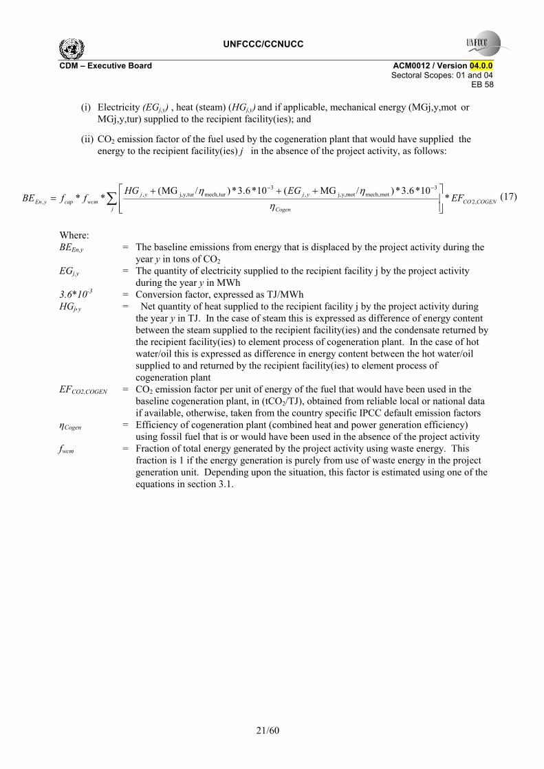
(i) Electricity (EGj,y) , heat (steam) (HGj,y) and if applicable, mechanical energy (MGj,y,mot or MGj,y,tur) supplied to the recipient facility(ies); and
(ii) CO2 emission factor of the fuel used by the cogeneration plant that would have supplied the energy to the recipient facility(ies) j in the absence of the project activity, as follows:
∑⎥⎥⎦
⎤
⎢⎢⎣
⎡ +++=
−−
jCOGENCO
Cogen
yjyjwcmcapyEn EF
EGHGffBE ,2
3motmech,moty,j,,
3turmech,tury,j,,
, *10*6.3*)/MG(10*6.3*)/MG(
**η
ηη (17)
Where: BEEn,y = The baseline emissions from energy that is displaced by the project activity during the
year y in tons of CO2 EGj,y = The quantity of electricity supplied to the recipient facility j by the project activity
during the year y in MWh 3.6*10-3 = Conversion factor, expressed as TJ/MWh HGj,y
= Net quantity of heat supplied to the recipient facility j by the project activity during the year y in TJ. In the case of steam this is expressed as difference of energy content between the steam supplied to the recipient facility(ies) and the condensate returned by the recipient facility(ies) to element process of cogeneration plant. In the case of hot water/oil this is expressed as difference in energy content between the hot water/oil supplied to and returned by the recipient facility(ies) to element process of cogeneration plant
EFCO2,COGEN = CO2 emission factor per unit of energy of the fuel that would have been used in the baseline cogeneration plant, in (tCO2/TJ), obtained from reliable local or national data if available, otherwise, taken from the country specific IPCC default emission factors
ηCogen = Efficiency of cogeneration plant (combined heat and power generation efficiency) using fossil fuel that is or would have been used in the absence of the project activity
fwcm = Fraction of total energy generated by the project activity using waste energy. This fraction is 1 if the energy generation is purely from use of waste energy in the project generation unit. Depending upon the situation, this factor is estimated using one of the equations in section 3.1.
UNFCCC/CCNUCC CDM � Executive Board ACM0012 / Version 04.0.0 Sectoral Scopes: 01 and 04
EB 58
22/60
fcap = Factor that determines the energy that would have been produced in project year y
using waste energy generated at a historical level expressed as a fraction of total energy produced using waste energy in year y. The ratio is 1 if the waste energy generated in project year y is same or less than that generated at a historical level. The value is estimated using Equations in section 3.2. For Greenfield facilities fcap is 1. If the procedure in annex-1 concludes that the waste energy would have been partially utilised in the �reference waste energy generating facilities� this fact in the factor fpractice (refer to the equations in section 1.2.2 for the use of factor fpractice)
MGj,y,mot = Mechanical energy generated by steam turbine in project activity and supplied to the mechanical equipment (e.g. pump, compressor) of recipient j, which in the absence of the project activity would be driven by electric motor (MWH). Refer to the guidelines in the monitoring table to estimate this parameter
ηmech,mot = The efficiency of the baseline equipment (electric motor) that would provide mechanical power in the absence of the project activity
MGj,y,tur = Mechanical energy generated by steam turbine in project activity and supplied to the mechanical equipment (e.g. pump, compressor) of recipient j, which in the absence of the project activity would be driven by steam turbine, operating from steam generated in a fossil fuel boiler (MWH). Refer to the guidelines in the monitoring table to estimate this parameter
ηmech,tur = The efficiency of the baseline equipment (steam turbine) that would provide mechanical power in the absence of the project activity
Efficiency of the existing cogeneration plant, (ηCogen) shall be one of the following:
(i) Assume a constant efficiency of the cogeneration plant and determine the efficiency, as a conservative approach, for optimal operation conditions i.e. designed fuel, designed steam extractions, optimal load, optimal oxygen content in flue gases, adequate fuel conditioning (viscosity, temperature, moisture, size/mesh etc), representative or favorable ambient conditions (temperature, humidity); or
(ii) Maximum efficiency of 90%, based on net calorific values (irrespective of type of cogeneration system and type of heat generated);
(iii) Estimated from load v/s efficiency curve(s) established through measurement of the cogeneration plant(s) . There are some guidelines provided in the �parameters not monitored� section. Follow international standards for estimation of efficiency of cogeneration plants.
(iv) The load-efficiency function for the cogeneration plant can be used from manufacturer�s specifications.
If recipient facility is a Greenfield facility and its baseline source of energy is cogeneration plant, refer to the definition of �reference energy generation facility� for the identification of the reference cogeneration plant. The efficiency of reference cogeneration plant (ηCogen) shall be determined as follows.
(a) Highest of the efficiency values provided by two or more manufacturers for �reference� cogeneration plant; or
(b) Assume a efficiency of 90% based on the net calorific value as a conservative approach; 1.2. Partial recovery of the WECM stream/s in the Baseline Scenario These project activities improve the recovery of the energy of WECM steam/s by retrofitting or replacing existing equipment or installing new equipment for additional energy recovery with an objective of (i)
UNFCCC/CCNUCC CDM � Executive Board ACM0012 / Version 04.0.0 Sectoral Scopes: 01 and 04
EB 58
23/60
recovering more quantity of WECM streams than that is (or would have been) recovered in the absence of project activity; or (ii) improving the efficiency of the energy recovery equipment; or (iii) both .
If multiple streams are recovered under one CDM project, and at least one stream would be partially recovered in the absence of the project the partial recovery adjustment described below should be considered for all the streams together.
All the equations (from 3 to 17) of baseline scenarios 1, 2 and 3 apply to the baseline emission calculation of these project activities provided the following adjustments are made.
1.2.1. Adjustment for an Existing Project Facility
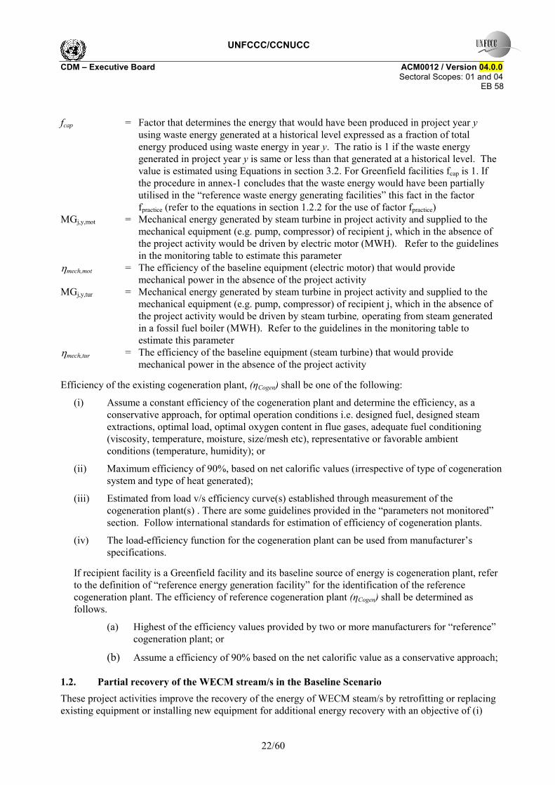
(i) Calculation of EGi,j,y or EGj,y that is referred to in equation (3) and (17): EGi,j,y or EGj,y should be the additional electricity generated by project activity, over and above historical generation that would have taken place in absence of project activity. It should be estimated based on the historical data of electricity generation from WECM stream in the absence of the project activity.
)(3/13
1,,,,, ∑
−=
−=
×−×=x
xxBLyPJyjyji EGEGFEG (18)
Note: This equation can be also used to determine EGj,y. EGi,j,y = The quantity of electricity supplied to the recipient j by generator, that in the absence
of the project activity would have been sourced from ith source (i can be either grid or identified source) during the year y in MWh
EGPJ,y = The total quantity of electricity generated from the identified WECM stream/s during the year y in MWh
EGBL,x = The quantity of electricity generated in absence of project activity from the identified WECM stream/s during the year x in MWh
Fj,y = Fraction of total electricity generated by the project activity, that is supplied to recipient j in year y (%)
x= -1 to -3
= Historical three years previous to implementation of project activity
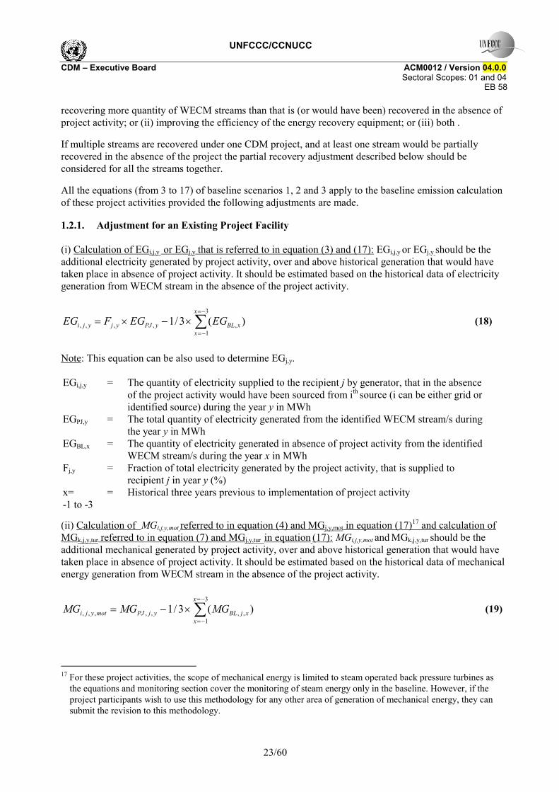
(ii) Calculation of MGi,j,y,mot referred to in equation (4) and MGj,y,mot in equation (17)17 and calculation of MGk,j,y,tur referred to in equation (7) and MGj,y,tur in equation (17): MGi,j,y,mot and MGk,j,y,tur should be the additional mechanical generated by project activity, over and above historical generation that would have taken place in absence of project activity. It should be estimated based on the historical data of mechanical energy generation from WECM stream in the absence of the project activity.
)(3/13
1,,,,,,, ∑
−=
−=
×−=x
xxjBLyjPJmotyji MGMGMG (19)
17 For these project activities, the scope of mechanical energy is limited to steam operated back pressure turbines as
the equations and monitoring section cover the monitoring of steam energy only in the baseline. However, if the project participants wish to use this methodology for any other area of generation of mechanical energy, they can submit the revision to this methodology.
UNFCCC/CCNUCC CDM � Executive Board ACM0012 / Version 04.0.0 Sectoral Scopes: 01 and 04
EB 58
24/60
)(3/13
1,,,,,,, ∑
−=
−=
×−=x
xxjBLyjPJturyjk MGMGMG (20)
Note: These equations can also be used to determine MGj,y,mot and MGj,y,tur. MGi,j,y,mot = Mechanical energy generated by steam turbine in project activity and supplied to the
mechanical equipment (e.g. pump, compressor) of recipient j, which in the absence of the project activity would be driven by electric motor ï�(MWH)
MGk,j,y,tur = Mechanical energy generated by steam turbine in project activity and supplied to the mechanical equipment (e.g. pump, compressor) of recipient j, which in the absence of the project activity would be driven by steam turbine k, operating from steam generated in a fossil fuel boiler (TJ)
MGPJ,j,y = The total quantity of mechanical energy supplied by steam turbine operated by steam generated using waste energy of identified WECM stream/s (in terms of TJ in the year y)
MGBL,j,x = The total quantity of mechanical energy supplied by steam turbine operated by steam generated using waste energy of the identified WECM stream/s (in terms of TJ in the year x)
x= -1 to -3
= Historical three years previous to implementation of project activity
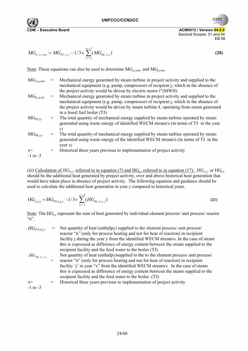
(iii) Calculation of HGn,j,y referred to in equation (7) and HGj,y referred to in equation (17): HGn,j,y or HGj,y should be the additional heat generated by project activity, over and above historical heat generation that would have taken place in absence of project activity. The following equation and guidance should be used to calculate the additional heat generation in year y compared to historical years.
)(3/1- HG HG3
1,,,yj,n,PJ,yj,n, ∑
−=
−=
×=x
xxjnBLHG (21)
Note: The HGj,y represent the sum of heat generated by individual element process/ unit process/ reactor �n�.
HGPJ,n,j y = Net quantity of heat (enthalpy) supplied to the element process/ unit process/ reactor �n� (only for process heating and not for heat of reaction) in recipient facility j during the year y from the identified WECM stream/s. In the case of steam this is expressed as difference of energy content between the steam supplied to the recipient facility and the feed water to the boiler (TJ)
xjnBLHG ,,,
=
Net quantity of heat (enthalpy)supplied to the to the element process/ unit process/ reactor �n� (only for process heating and not for heat of reaction) in recipient facility �j� in year �x� from the identified WECM stream/s . In the case of steam this is expressed as difference of energy content between the steam supplied to the recipient facility and the feed water to the boiler. (TJ)
x= -1 to -3
= Historical three years previous to implementation of project activity
UNFCCC/CCNUCC CDM � Executive Board ACM0012 / Version 04.0.0 Sectoral Scopes: 01 and 04
EB 58
25/60
1.2.2. Adjustment for a Greenfield Project Facility
If the energy recovery project is implemented in a Greenfield waste energy generating facility, and the �reference waste energy generating facility� identified (refer to definition of �reference waste energy generating facility� and annex-1) shows that the WECM stream/s would have been partially recovered or recovered with lower efficiency, the following equations should be used.
(i) Calculation of EGi,j,y or EGj,y that is referred to in equation (3) and (17):: EGi,j,y or EGj,y should be the additional electricity generated by project activity, over and above over and above the generation that would have taken place in reference waste generation facility.
practiceyPJyjyji fEGFEG ××= ,,,, (22)
Note: This equation can also be used to determine EGj,y.
EGi,j,y = The quantity of electricity supplied to the recipient j by generator, that in the absence of the project activity would have been sourced from ith source (i can be either grid or identified source) during the year y in MWh
EGPJ,y = The total quantity of electricity generated from the identified WECM stream/s during the year y in MWh
fpractice = The factor determined by the practice of �reference waste energy generating facility�, to be calculated using the guidelines given in Annex-1. It represents the extent to which the �reference waste energy generating facility� would have recovered the electricity from identified WECM stream/s in the baseline
Fj,y = Fraction of total electricity generated by the project activity, that is supplied to recipient j in year y (%)
(ii) Calculation of MGi,j,y,mot referred to in equation(4) and (17)18 and calculation of MGk,j,y,tur referred to in equation (7) and (17): MGi,j,y,mot and MGk,j,y,tur should be the additional mechanical generated by project activity, over and above the generation that would have taken place in reference waste generation facility. .
practiceyjPJmotyji fMGMG ×= ,,,,, (23)
practiceyjPJturyjk fMGMG ×= ,,,,, (24)
Note: These equations can also be used to determine MGj,y,mot and MGj,y,tur. MGi,j,y,mot = Mechanical energy generated by steam turbine in project activity and supplied to the
mechanical equipment (e.g. pump, compressor) of recipient j, which in the absence of the project activity would be driven by electric motor ï�(MWH)
MGk,j,y,tur = Mechanical energy generated by steam turbine in project activity and supplied to the mechanical equipment (e.g. pump, compressor) of recipient j, which in the absence of the project activity would be driven by steam turbine k, operating from steam generated in a fossil fuel boiler (TJ)
MGPJ,j,y The total quantity of mechanical energy supplied by steam turbine operated by steam
18 For these project activities, the scope of mechanical energy is limited to steam operated back pressure turbines as
the equations and monitoring section cover the monitoring of steam energy only in the baseline. However, if the project participants wish to use this methodology for any other area of generation of mechanical energy, they can submit the revision to this methodology.
UNFCCC/CCNUCC CDM � Executive Board ACM0012 / Version 04.0.0 Sectoral Scopes: 01 and 04
EB 58
26/60
generated using waste energy of identified WECM stream/s (in terms of TJ in the year y)
fpractice = The factor determined by the practice of �reference waste energy generating facility�, to be calculated using the guidelines given in Annex-1. It represents the extent to which the �reference waste energy generating facility� would have recovered the electricity from identified WECM stream/s in the baseline
(iii) Calculation of HGn,j,y referred to in equation (7) and HGj,y referred to in equation (17): HGn,j,y or HGj,y should be the additional heat generated by project activity, over and above the generation that would have taken place in reference waste generation facility.
practicef×+= )HG (HG HG yj,chemical,n,yj,process,n,yj,n,
(25)
Note: The HGj,y represent the sum of heat generated by individual element process/ unit process/ reactor �n�.
HGn,process,j,y = Net quantity of heat (enthalpy) supplied to the recipient facility j for element process/ heating unit / chemical reactor �n� by the project activity for process heating during the year y. In the case of steam this is expressed as difference of energy content between the steam supplied to the recipient facility and the feed water to the boiler (TJ)
HGn,chemicals,j,y = Net quantity of heat (enthalpy)supplied to the recipient facility �j� for chemical reactor �n� by the project activity for supply of heat of reaction during the year y (TJ)
fpractice = The factor determined by the practice of �reference waste energy generating facility�, to be calculated using the guidelines given in Annex-1. It represents the extent to which the �reference waste energy generation facility� would have recovered the electricity from identified WECM stream/s in the baseline
2. Baseline Emissions From Flaring of Waste Gas (BEflst,y)
This portion of baseline emissions occurs only when the waste energy carrying medium (WECM) is waste gas and the waste gas would be flared with fossil fuel or steam in the baseline scenario. If there is no plant specific historic data available to estimate the various parameters then the emissions from this source shall be conservatively excluded from the baseline emissions.
EF* jCO2,,,, ∑=j
ystffyflst QBE (26)
Where: ystffQ ,, = Amount of fossil fuel that would have been needed in facility either directly or to
generate steam that would have been used to flare waste gas, generated in year y, in absence of the project activity (TJ)
j,2COEF = CO2 emission factor of fossil fuel (tCO2/TJ) that would have been used at facility j 2.1. Flaring with Fossil Fuels
For the project activities improving energy recovery as compared to baseline, if the fossil fuel is used in the absence of project activity to flare the waste gas then the value of Qff,st,y shall be calculated as:
WGBLWGyWGystff FFQQQ *)( ,,,, −= (27)
UNFCCC/CCNUCC CDM � Executive Board ACM0012 / Version 04.0.0 Sectoral Scopes: 01 and 04
EB 58
27/60
Where: QWG,y = Quantity of waste gas used for energy generation during year y (T) QWG, BL = Quantity of waste gas captured and used for energy generation in the absence of the
project activity (T), use the maximum figure from 3 years historic data FFWG = Fossil fuel required per unit of waste gas flared, in terms of energy content, (TJ/unit
waste gas)
BFlWG
BflffWG Q
QFF
,,
,,= (28)
BFlWGQ ,, = The amount of waste gas flared using fossil fuel prior to the implementation of the project activity (T, kg or m3
at NTP). Three years historic data shall be used. BflffQ ,, = Fossil fuel used to flare the waste gas prior to the implementation of the project
activity (TJ). Three years historic data shall be used.
2.2. Flaring with Steam
If steam is used instead of fossil fuel for flaring of the waste gas, the fossil fuel consumption can be estimated as follows:
flBoiler
WGBLWGyWGystff
SFQQQ
,
,,,,
*)(η−
= (29)
Where: y,WGQ = Quantity of waste gas used for energy generation during year y (T)
QWG, BL = Quantity of waste gas captured and used for energy generation in the absence of the project activity , use the maximum figure from 3 years historic data (kg)
WGSF = Steam required per unit of waste gas flared, in terms of energy content, (TJ/unit waste gas)
flBoiler ,η = Efficiency of the boiler that would have been used to generate the steam in absence of the project activity. The guidelines for determining the efficiency for baseline element process (ηEP,i,j ) in earlier sections, shall be used to determine this efficiency
BFlWG
BflstWG Q
QSF
,,
,,= (30)
Where: B,Fl,WGQ = The amount of waste gas flared using steam prior to the implementation of the project
activity (T, kg or m3 at NTP). Three years historic data shall be used
B,fl,stQ = Steam used to flare the waste gas prior to the implementation of the project activity (TJ). Three years historic data shall be used
UNFCCC/CCNUCC CDM � Executive Board ACM0012 / Version 04.0.0 Sectoral Scopes: 01 and 04
EB 58
28/60
3. Estimation of Various Baseline Factors 3.1. Fraction of Energy Produced by the project activity
This is not applicable to project activities that use waste pressure to generate electricity; as for such project activities the electricity generated using waste pressure should be measurable.
3.1.1. Electricity and Heat Generation from WECM and fossil fuels
The procedure specified below, should be applied when the direct measurement of the electricity/heat generated using the WECM is not possible as other fossil fuel(s) along with WECM are used for energy generation. The relative share of the total generation from WECM is calculated by ratio of energy supplied by WECM to the total amount input energy fed by WECM and other fuels used, and the average efficiency of the plants where the energy is produced.
The fraction of energy produced by using the WECM in the project activity is calculated as follows :
∑∑
∑
= =
=
+−
+−= 8760
1 1,,
8760
1,,,
))(*(*
))(*(*
h
I
iirefhiihi
hyWCMrefhwcmwcmhWCM
WCM
NCVttCpQ
NCVttCpQf (31)
If the waste energy is used for heat generation in unit process �n�, fWCM,n,y can be calculated as follows.
∑∑
∑
= =
=
+−
+−= 8760
1 1,,,,
8760
1,,,,,
,,
))(*(*
))(*(*
h
I
iirefhniihni
hyWCMrefhnwcmwcmhnWCM
ynWCM
NCVttCpQ
NCVttCpQf (32)
Where: fWCM = Fraction of total electricity or mechanical energy generated by the project activity using
waste energy fWCM,n,y = Fraction of total heat generated in the unit process / element process/ reactor �n� by the
project activity using waste energy. QWCM,h = Quantity of WECM recovered (T/h) in hour h NCVWCM,y = Net Calorific Value of WECM in year y (TJ/T) Cpwcm = Specific Heat of WECM (TJ/T-deg C or other suitable unit) twcm,h = The temperature of WECM in hour h (deg C or other applicable unit) tref = Reference temperature (0 deg C or any other suitable reference temperature with proper
justification) Qi,h = Amount of individual fuel (WECM and other fuel(s)) i consumed at the energy generation
unit during hour h (T) Cpi = Specific Heat of WECM i (TJ/T -deg C or other suitable unit) NCVi = Net Calorific Value annual average for each individual consumed fuel including WECM
(TJ/T) ti,h = The temperature of individual fuel (WECM and other fuel(s)) i consumed at the energy
generation unit during hour h (deg C or other applicable unit) tref = Reference temperature (0 deg C or any other suitable reference temperature with proper
justification) Qwcm,n,h = Quantity of waste energy consumed in unit process �n� during hour h.
UNFCCC/CCNUCC CDM � Executive Board ACM0012 / Version 04.0.0 Sectoral Scopes: 01 and 04
EB 58
29/60
Qi,n,h = Amount of individual fuel (WECM and other fuel(s)) i consumed in unit process �n� during hour h (T)
ti,n,h = The temperature of individual fuel (WECM and other fuel(s)) i consumed in the unit process �n� during hour h (deg C or other applicable unit)
Note: If index i represents fossil fuels, the energy content corresponding to the sensible heat of fossil fuel i should be zero, as given follows.
0)(** ,, =− refhiihi ttCpQ (33)
3.1.2. Steam Generation from WECM and fossil fuels
An alternative method that could be used when it is not possible to measure the net calorific value of the waste gas/heat, and steam generated with different fuels in dedicated boilers are fed to turbine/s through common steam header takes into account that the relative share of the total generation from WECM is calculated by considering the total steam produced and the amount of steam generated from each boiler. The fraction of energy produced by the waste gas/heat WECM in project activity is calculated as follows:
yotherywhr
ywhrWCM STST
STf
,,
,
+= (34)
Where: ywhrST , = Energy content of the steam generated in waste heat recovery boiler fed to turbine via
common steam header (TJ) yotherST , = Energy content of steam generated in other boilers fed to turbine via common steam
header (TJ)
This alternative method requires that:
• All the boilers have to provide superheated steam;
• The calculation should be based on the energy supplied to the steam turbine. The enthalpy and the steam flow rate must be monitored for each boiler to determine the steam energy content. The calculation implicitly assumes that the properties of steam (temperature and pressure) generated from different sources are the same. The enthalpy of steam and feed water will be determined at measured temperature and pressure and the enthalpy difference will be multiplied with quantity measured by steam meter;
• Any vented steam should be deducted from the steam produced with waste gas/heat.
3.2. Capping factors
The methodology requires the baseline emissions to be capped irrespective of planned/unplanned or actual increase in output of plant, change in operational parameters and practices, change in fuel type and quantity resulting in an increase in generation of waste energy. The cap can be estimated using the three methods19 described below , following this hierarchy: (i) Method-1 can be used to estimate the capping factor if required data is available; (ii) if the project activities implemented in a Greenfield facility, or in existing facilities where the required data is unavailable method-2 shall be used; (iii) If the project
19 In case the methods for determination of capping factor described in this section do not apply to the situation of
project of the project participants, they may consider submitting new approaches to determine this factor.
UNFCCC/CCNUCC CDM � Executive Board ACM0012 / Version 04.0.0 Sectoral Scopes: 01 and 04
EB 58
30/60
proponents demonstrate technical infeasibility in direct monitoring of waste heat / pressure of waste energy carrying medium (WECM), then Method-3 is used.
3.2.1. Method-1
Where the historical data on energy released by the waste energy carrying medium is available, the baseline emissions are capped at the maximum quantity of waste energy released into the atmosphere under normal operation conditions in the three years previous to the project activity.
For that purpose fcap is estimated as follows: The different equations are used depending upon the type of energy recovered from waste energy carrying medium (WECM) (e.g. waste gas, air, steam) in project activity.
Case 1: If the waste energy is in the form of waste heat of WECM (e.g. gas, waste gas, air)
)/)10/81.9()()(()/)10/81.9()()((
,9
,,,,
,9
,,,,
ywcmrefyWCMyWCMrefywcmWCMyWCM
BLwcmrefBLWCMBLWCMrefBLwcmWCMBLWCMcap dPPNCVttCpQ
dPPNCVttCpQf
×−++−×××−++−××
= (35)
Note: Even if primarily energy recovery is based on waste heat, there can be additional energy recovery due to increased pressure of WECM, which can be estimated using pressure differential.
Case 2: If the waste energy recovered is in the form of waste pressure of WECM (e.g. air, gas, waste gas)
ywcmrefyWCMyWCM
BLwcmrefBLWCMBLWCMcap dPPQ
dPPQf
,,,
,,,
/)(/)(
−×−×
= (36)
Case 3: If the waste energy recovered is in the form of enthalpy, which depends upon the pressure, and temperature of waste energy carrying medium (e.g. steam)
)()(
,,
,,
refyWCMyWCM
refBLWCMBLWCMcap HHQ
HHQf
−×−×
= (37)
Where:
QWCM,BL = Average quantity of WECM released (or flared or wasted) in atmosphere in three years prior to the start of the project activity (T)
QWCM,y = Quantity of WECM used for energy generation during year y (T) Cpwcm = Specific Heat of waste energy carrying medium (WECM) (TJ/T/deg C)
ywcmt , = Average temperature of Waste Energy Carrying Medium (WECM) in year y (Deg C )
BLwcmt , = Average temperature of Waste Energy Carrying Medium (WECM) in three years prior to the start of the project activity (Deg C )
reft = Reference temperature to be used to determine available energy in WECM (either 0 deg C or 25 deg C )
UNFCCC/CCNUCC CDM � Executive Board ACM0012 / Version 04.0.0 Sectoral Scopes: 01 and 04
EB 58
31/60
NCVWCM,y = Average net calorific value of waste gas in year y (if WECM is waste gas), which has unburnt components such as carbon particles, CO or CH4 that will provide energy in waste energy recovery equipment from its combustion (TJ/T)
NCVWCM,BL = Average net calorific value of waste gas (if WECM is waste gas), three years prior to implementation of project activity which has unburnt components such as carbon particles, CO or CH4 that will provide energy in waste energy recovery equipment from its combustion (TJ/T)
yWCMP , = Average pressure of WECM in year y (kg/m2 (a))
BLWCMP , = Average pressure of WECM in three years prior to the start of the project activity (kg/cm2 (a) )
refP = Reference pressure of WECM ( ambient pressure in kg/m2 or other appropriate pressure with proper justification))
yWCMH , = Average enthalpy of WECM in year y (TJ/T )
BLWCMH , = Average enthalpy of WECM in three years prior to the start of the project activity (TJ/T )
refH = Reference enthalpy to be used to determine available energy in WECM ( 0 TJ/T or other appropriate enthalpy with proper justification)
dwcm,y = Average density of WECM at actual temperature and pressure in year y (T/m3 at actual conditions)
dwcm,BL = Average density of WECM at actual temperature and pressure in three years prior to the start of the project activity (T/m3 at actual conditions)
9.81/109 = Factor to convert kg-m into TJ (To be used when pressure is expressed in kg/m2. For all other units of pressure, the conversion factor should be defined appropriately)
3.2.2. Method-2
If three-year historical data is not available, the manufacturer�s data for the facility shall be used to estimate the amount of waste energy the facility generates per unit of �product�. The �product� is produced by the process that generates waste energy (departmental process or process of entire project facility, whichever is more justifiable and accurate). If any modification is carried out by the project proponent or if the manufacturer�s data is not available for an assessment, this should be carried out by independent qualified/certified external process experts such as a chartered engineer on a conservative quantity of waste energy generated by project facility per unit of product manufactured by the process generating waste energy. The value arrived based on above sources of data, shall be used to estimate the baseline cap (fcap). Under this method, following equations should be used to estimate fcap.
yWCM
BLWCMcap Q
Qf
,
,= (38)
productwcmproductBLBLWCM qQQ ,,, ×= (39)
Where: QWCM,BL = Quantity of waste energy generated prior to the start of the project activity. (T of
WECM or other relevant unit)
UNFCCC/CCNUCC CDM � Executive Board ACM0012 / Version 04.0.0 Sectoral Scopes: 01 and 04
EB 58
32/60
productBLQ , = Production associated with the relevant waste energy generation as it occurs in the
baseline scenario. The minimum of the following two figures should be used: (1) average annual historical production data from start-up of the facility, if the facility�s operational history is less than three years, or (2) the most relevant manufacture�s data for normal operating conditions. In the case of Greenfield facilities or where data is not available the manufacture�s data for normal operating conditions shall be used. (Units for product can be in no. of pieces, tons, m3 etc.)
q wcm, product = Amount of waste energy per unit of product generated by the process (that generates waste energy) in the facility. (Units in MWh/unit product or TJ/unit product)
3.2.3. Method-3
In some cases, it may not be possible to measure the waste energy (heat, sensible heat, heat of reaction, heat of combustion, etc.) enthalpy or pressure content of WECM (Method-1 requirement), neither the specific amount of WECM per unit of product (Method-2 requirement). In such cases, the capping shall be based on indirect information about specific parameters allowing to estimate the amount of waste energy available. These parameters should be related to the characteristics of a product or a by-product of the facility from which waste energy can be recovered (e.g. volume and heat content of hot clinker produced by a kiln in cement plant, if this heat can be recovered using air as the WECM). These cases may be of following two types.
Case 1: The energy is recovered from WECM and converted into final output energy through a waste heat recovery equipment. For example, the useful energy (eg, steam) is produced using waste energy generated by a chemical reaction. For such cases fcap should be the ratio of maximum energy that could be recovered (MER) by the waste heat recovery equipment implemented under the CDM project activity and the actual energy recovered under the project activity (using direct measurement). The MER should be based on information on the characteristics of the key product / by product . For existing facilities this can be obtained from historical information and for Greenfield facilities, manufacturer�s specifications on these key parameters can be used.
Case 2: The energy is recovered from WECM in an intermediate energy recovery equipment using an intermediate source. For example, an intermediate source to carry energy from primary WECM may include the sources such as water, oil or air to extract waste energy entrapped in chemicals (heat of reaction) or solids (sensible heat), which is further recovered in the waste heat recovery equipment to generate final output energy. For such cases fcap should be the ratio of maximum energy that could be recovered (MER) by waste heat recovery equipment implemented under the CDM project activity (considering the losses due to exchange of energy) and actual intermediate energy recovered under the project activity (using direct measurement). The MER should be based on information on the characteristics of the key product / by product. For existing facilities this can be collected from historical information and for Greenfield facilities, manufacturers specifications on these key parameters can be used.
Following equation should be used to determine fcap:
yOE
BLOEcap Q
Qf
,
,= (40)
UNFCCC/CCNUCC CDM � Executive Board ACM0012 / Version 04.0.0 Sectoral Scopes: 01 and 04
EB 58
33/60
Where: QOE,BL = Output/intermediate energy that can be produced (in appropriate unit), to be determined
on the basis of maximum energy that could be recovered from the WECM (MER), which would have been released (or WECM would have been flared or energy content of WECM would have been wasted) in the absence of CDM project activity
QOE,y = Quantity of actual output/intermediate energy generated during year y (in appropriate unit)
Project Emissions
Project Emissions include emissions due to (1) combustion of auxiliary fuel to supplement waste gas/heat and (2) electricity emissions due to consumption of electricity for cleaning of gas before being used for generation of energy or other supplementary electricity consumption.
yELyAFy PEPEPE ,, += (41)
Where: yPE = Project emissions due to project activity
yAFPE , = Project activity emissions from on-site consumption of fossil fuels by the unit process(s) and/or co-generation plant(s), if they are used as supplementary fuels, due to non-availability of waste energy to the project activity or due to any other reason
yELPE , = Project activity emissions from on-site consumption of electricity for gas cleaning equipment or other supplementary electricity consumption (as per Table 1: Summary of gases and sources included in the project boundary)
Note: If the electricity was consumed in gas cleaning equipment in the baseline as well, project emissions due to electricity consumption for gas cleaning can be ignored.
(1) Project emissions due to auxiliary fossil fuel combusted to supplement waste energy in the project activity
These project emissions should be calculated only in two situations : (1) auxiliary fossil fuel is used to supplement the waste energy directly in the waste heat recovery combustion systems, where the energy output cannot be apportioned between fossil fuels and the waste energy, and (2) the calculation of Fwcm using Equation 31, 32 and 34 is practically not possible due to technical constraints (e.g. gas measurement and its quality).In all other cases, if the calculation of Fwcm has accounted for the use of the auxiliary fossil fuels, then the calculation of the project emissions for the auxiliary fossil fuels is not required.
These emissions are calculated by using latest approved tool �Tool to calculate project or leakage CO2 emissions from fossil fuel combustion�.
(2) Project emissions due to electricity consumption of gas cleaning equipment or other supplementary electricity consumption
These project emissions are calculated by using latest approved tool �Tool to calculate baseline, project and/or leakage emissions from electricity consumption�.
Leakage
No leakage is applicable under this methodology.
UNFCCC/CCNUCC CDM � Executive Board ACM0012 / Version 04.0.0 Sectoral Scopes: 01 and 04
EB 58
34/60
Emission Reductions
Emission reductions due to the project activity during the year y are calculated as follows:
yyy PEBEER −= (42)
Where: yER = Total emissions reductions during the year y in tons of CO2
yPE = Emissions from the project activity during the year y in tons of CO2
yBE = Baseline emissions for the project activity during the year y in tons of CO2, applicable to Scenario 2
Data and parameters not monitored
Data / Parameter: ηBL (ηEP,i,j,ηmech,mot,i,j, ηmech,tur,k, ηPlant,j, ηCogen, ) Data unit: Description: Baseline efficiency of the element process/mechanical energy conversion
equipment/captive power plant/cogeneration plant in recipient plant �j� Source of data: Manufacturers data or data from similar plant operators or project participants
data Measurement procedures (if any):
For efficiency of captive power plant or element process, refer to the options provided in the section of baseline emissions. For mechanical energy conversion equipment, apart from the options available in the baseline emission section (electrical motor or steam turbine in baseline which is replaced by mechanical turbine of CDM project), use the equipment efficiency vs. load characteristic curve from the supplier. For efficiency of cogeneration plant, apart from options available in baseline section, following procedure should be followed. Establish an efficiency-load-function for the cogeneration plant . Use recognized standards for the measurement of the element process efficiency, for cogeneration efficiency measurement. Use the direct method (dividing the net energy generation by the energy content of the fuels fired during a representative time period) and not the indirect method (determination of fuel supply or energy generation and estimation of the losses). Best practices for operation of cogeneration plant should be followed. The measurement should be supervised by a competent independent third party (e.g. the DOE). The measurement should be conducted immediately after scheduled preventive maintenance has been undertaken and under good operation conditions (optimal load, optimal oxygen content in the flue gases, adequate fuel viscosity, representative or favorable ambient conditions for the efficiency of the boiler, etc). During the measurement campaign, the load is varied over the whole operation range and the efficiency is measured for different steady-state load levels. The efficiency should be measured for at least 10 different load levels covering the operation range. Apply a regression analysis to the measured efficiency for different load levels. Document the measurement procedures and results (i.e. efficiency at different load levels, application of the regression analysis) transparently in the CDM-PDD or, if undertaken during the crediting period, in the monitoring report
Any comment: Data / Parameter: QWCM,BL
UNFCCC/CCNUCC CDM � Executive Board ACM0012 / Version 04.0.0 Sectoral Scopes: 01 and 04
EB 58
35/60
Data unit: Mass unit (T) of WECM or other relevant unit Description: Average quantity of WECM released in atmosphere in three years prior to the
start of the project activity Source of data: Direct Measurements by generator of WECM through an appropriate metering
device (e.g. turbine flow meter) for three years prior to implementation of project activity. In the case of Method-2 (to determine fcap) source of data is manufacturer�s specifications or external expert to be used to determine QWCM,BL.
Measurement procedures (if any):
For facility, it is determined by either of two methods: (1) Direct measurements of amount of the waste energy for at least three
years prior to the start of the project activity; (2) As described in Method-2 of Section 3.2.2, estimated based on
information provided by the technology supplier and the external expert on the waste energy generation per unit of product and volume or quantity of production.
Any comment: In the case of modification of project facility the Method-2 can be used as stated above. In the case where a portion of the waste energy is captured and utilised to generate captive electricity in the absence of the project activity, QWCM,BL represents the total amount of waste energy generated at the facility and not only the waste energy flared/vented in the absence of the project activity
Data / Parameter: reft , refP , refH Data unit: deg C , kg/cm2 (a), TJ/T respectively or other appropriate unit Description: Reference temperature, pressure and enthalpy Source of data: Use the following values or other appropriate pressure with proper justification:
0 for reference temperature; 1 atm for reference pressure; 0 TJ/T for reference enthalpy
Measurement procedures (if any):
Any comment: Data / Parameter: twcm,BL Data unit: deg C Description: Average temperature of WECM in three years prior to the start of the project
activity Source of data: To be measured using appropriate temperature measuring instrument (e.g.
Pressure gauge, Manometer etc.) Measurement procedures (if any):
To be averaged based on daily measured values
Any comment:
UNFCCC/CCNUCC CDM � Executive Board ACM0012 / Version 04.0.0 Sectoral Scopes: 01 and 04
EB 58
36/60
Data / Parameter: BLWCMP , Data unit: kg/m2 Description: Average pressure of WECM in three years prior to the start of the project
activity Source of data: To be measured using appropriate pressure measuring instrument (e.g. Pressure
gauge, Manometer etc.) Measurement procedures (if any):
To be averaged based on daily measured values
Any comment: Data / Parameter: BLWCMH , Data unit: TJ/T Description: Average enthalpy of WECM in three years prior to the start of the project
activity Source of data: From engineering data books (e.g. steam tables) Measurement procedures (if any):
Measure daily temperature and pressure of WECM, average it annually. At yearly averaged value of pressure and temperature, find enthalpy of WECM
Any comment: Data / Parameter: dwcm,BL Data unit: (T/m3 at actual conditions) Description: Density of WECM at actual temperature and pressure in three years prior to the
start of the project activity (T/m3 at actual conditions) Source of data: From standard data books Measurement procedures (if any):
Any comment: The density figure used for calculations should correspond to average pressure and temperature of WECM
Data / Parameter: QOE,BL Data unit: Appropriate unit such as TJ, MWh Description: Output/intermediate energy that can be produced, to be determined on the basis
of maximum energy that could be recovered from the WECM (MER), which would have been released (or WECM would have been flared or energy content of WECM would have been wasted) in the absence of CDM project activity
Source of data: The MER should be based on information on the characteristics of the key product / by product. For existing facilities this can be collected from historical information and for Greenfield facilities, manufacturers specifications on these key parameters can be used.
Measurement procedures (if any):
Any comment:
UNFCCC/CCNUCC CDM � Executive Board ACM0012 / Version 04.0.0 Sectoral Scopes: 01 and 04
EB 58
37/60
Data / Parameter: Qff,,fl,B Data unit: TJ Description: Fossil fuel used to flare (directly) the waste gas prior to the implementation of
the project activity. Three years historic should be used. Source of data: Measured by project participants Measurement procedures (if any):
Calibrated flow meter
Any comment: Data / Parameter: QWG,Fl,B Data unit: T or m3 at NTP Description: The amount of waste gas flared using steam prior to the implementation of the
project activity. Three years historic data shall be used. Source of data: Generators of gas Measurement procedures (if any):
Measured directly through appropriate metering device (e.g. turbine flow meter)
Any comment: Data / Parameter: productBLQ , Data unit: (Tons/yr or m3/yr or other relevant unit) Description: Production associated with the relevant waste energy generation as it occurs in
the baseline scenario. The minimum of the following two figures should be used: (1) historical production data from start-up, if project facility operational history is less than three years, of the project facility or (2) the most relevant manufacture�s data for normal operating conditions. In the case of Greenfield facilities or where data is not available the manufacture�s data for normal operating conditions shall be used
Source of data: Project proponents and/or manufacturer Measurement procedures (if any):
Based on audited production records, balance sheets etc. Data for three years prior to project implementation
Any comment: Data / Parameter: productwcmq , Data unit: (kg, tons or m3 / (at NTP) TJ, Pa, or other relevant units per unit of product) Description: Specific waste energy production per unit of product (departmental or project
facility product which most logically relates to waste energy generation) generated as per manufacturer�s or external expert�s data. This parameter should be analysed for each modification in process which can potentially impact the waste energy quantity
Source of data: Project participant, manufacturer or external expert. Data for three years prior to project implementation
Measurement procedures (if any):
From manufacturer�s specification Assessment of external expert
Any comment: Data / parameter: TEp
UNFCCC/CCNUCC CDM � Executive Board ACM0012 / Version 04.0.0 Sectoral Scopes: 01 and 04
EB 58
38/60
Data unit: TJ/ton Description: Total enthalpy of steam from steam table, if steam is a product of a process
(steam boiler) Source of data: From standard data books/ steam tables Measurement procedures (ifnyany):
Any comment: Data / parameter: TEr Data unit: TJ/ton Description: Total enthalpy of steam from steam table, if steam is reactant in the process
(e.g. chemical reaction where steam is one of the reactants) Source of data: From standard data books/ steam tables Measurement procedures (ifnyany):
Any comment: Data / parameter: HFp Data unit: TJ/kMol Description: Standard heat of formation of product �p� in the product mix at the outlet of
the reactor
Source of data: From standard data books Measurement procedures
Any comment: Heat of formation could be positive or negative, proper mathematical sign should be used while using these values in the equation
Data / parameter: HFr Data unit: TJ/kMol Description: Standard heat of formation of reactant �r� in the reactant mix at the intlet of the
reactor
Source of data: From standard data books Measurement procedures (if any):
Any comment: Heat of formation could be positive or negative, proper mathematical sign should be used while using these values in the equation
UNFCCC/CCNUCC CDM � Executive Board ACM0012 / Version 04.0.0 Sectoral Scopes: 01 and 04
EB 58
39/60
Data / Parameter: EGBL,x Data unit: MWh Description: The quantity of electricity generated in absence of project activity from the
identified WECM stream/s during the year x . Source of data: Measured by project participants Measurement procedures (if any):
Measured through an appropriate metering device for three years prior to implementation of project activity.
Any comment: This parameter is necessary to find out the extent to which the WECM stream/s are already recovered in absence of project activity.
Data / Parameter: MGBL,j,x Data unit: TJ of steam Description: The total quantity of mechanical energy supplied by steam turbine operated by
steam generated using waste energy of the identified WECM stream/s (in terms of TJ in the year x).
Source of data: Measured by project participants Measurement procedures (if any):
Follow the procedure as specified for MGj,y,mot , MGj,y,tur to estimate Mechanical energy delivered by the turbine in absence of project activity. The share of mechanical energy delivered by the turbine, pertaining to the steam generated using waste energy can be estimated by multiplying the Mechanical energy by the ratio of steam supplied by waste energy recovery boiler using waste energy of identified WECM stream/s and the total steam supplying to the turbine
Any comment: This parameter is necessary to find out the extent to which the WECM stream/s are already recovered in absence of project activity.
Data / Parameter: Hwcm,BL Data unit: TJ Description: Energy supplied, using WECM stream/s, as heat for process and/or as a heat of
reaction to chemical reaction, in project year y Source of data: Project participant�s data Measurement procedures (if any):
This energy is to be determined based on energy supplied to the process or chemical reaction (and not received by the process or chemical reaction). For example, it should be the heat supplied by a waste heat recovery boiler to the chemical process to meet the demand of heat of reaction (and not calculated ). Appropriate measurement instruments should be adopted for the type of energy supplied to process or chemical reaction
Any comment: This indirect method is needed because the energy (heat) received by process or chemical reaction will remain same in the project and baseline scenario. Only the fossil fuel based heat supplied in baseline will be displaced (either fully or partly) by the recovered heat from WECM stream/s
UNFCCC/CCNUCC CDM � Executive Board ACM0012 / Version 04.0.0 Sectoral Scopes: 01 and 04
EB 58
40/60
Data / Parameter: Qst,,fl,B Data unit: TJ Description: Steam used to flare the waste gas prior to the implementation of the project
activity. Three years historic should be used Source of data: Measured by project participants Measurement procedures (if any):
Calibrated Steam meter
Any comment: Data / Parameter: QWG, BL Data unit: T Description: Quantity of waste energy captured and used for energy generation in the
absence of the project activity, use the maximum figure from 3 years historic data
Source of data used: Project participant information Measurement procedures (if any):
Measured by project participants (generator of energy) through an appropriate metering device (calibrated flow meters) for three years prior to implementation of project activity.
Any comment: Applicable in the case where a portion of the waste energy is captured and utilised to generate captive electricity in the absence of the project activity
Data / Parameter: xjnBLHG ,,, Data unit: (TJ) Description: Net quantity of heat (enthalpy)supplied to the to the element process/ unit
process/ reactor �n� (only for process heating and not for heat of reaction) in recipient facility �j� in year �x� from the identified WECM stream/s . In the case of steam this is expressed as difference of energy content between the steam supplied to the recipient facility and the feed water to the boiler. (TJ)
Source of data used: Project participants information Measurement procedures (if any):
Measured by project participants through an appropriate metering device (calibrated flow meters) for three years prior to implementation of project activity
Any comment: Data / Parameter: NCVWCM,BL Data unit: (TJ/T) Description: Average net calorific value of waste gas (if WECM is waste gas), three years
prior to implementation of project activity which has unburnt components such as carbon particles, CO or CH4 that will provide energy in waste energy recovery equipment on combustion of gas (TJ/T)
Source of data used: Project participants information Measurement procedures (if any):
Measured by project participants through an appropriate device.
Any comment: Average of measured data of three years prior to implementation of project activity, to be considered
UNFCCC/CCNUCC CDM � Executive Board ACM0012 / Version 04.0.0 Sectoral Scopes: 01 and 04
EB 58
41/60
III. MONITORING METHODOLOGY
All data collected as part of monitoring plan should be archived electronically and be kept at least for 2 years after the end of the last crediting period. 100% of the data should be monitored if not indicated otherwise in the comments in the tables below. The following main data shall be monitored.
Project emissions:
(1) Quantity of fossil fuels used as supplementary fuel;
(2) Net calorific value of fossil fuel;
(3) CO2 emission factor of the fossil fuel;
(4) Quantity of electricity consumed by the project operations;
(5) CO2 emissions factor of electricity consumed by the project operations.
(6) Abnormal operation of plant.
While the quantity of fossil fuels fired are measured using calibrated flow meters, other data items are only factors obtained from reliable local or national data. If local data is not available, project participant may use default factors published by IPCC.
Baseline Emissions:
Depending on the baseline scenario, the following data items need monitoring.
(1) The heat/ power/ mechanical energy supplied by project facility to recipient facility(ies) by recovering waste energy from WECM stream/s;
(2) Energy generation using WECM, in absence of project activity;
(3) Quantity and energy content of WECM;
(4) CO2 emission factor of electricity or heat that would have been consumed by the of recipient facility(ies) in the absence of the project activity;
(5) Properties of heat (e.g. pressure and temperature of the inlet and outlet of the streams, concentrations of the reactant/product mix etc.) supplied to the recipient facility(s);
(6) Properties of heat return to element process (e.g. pressure and temperature of the condensate return) supplied by the recipient facility(s) to the project facility;
(7) Efficiencies of element process, power plant, cogeneration plant or mechanical conversion equipment that would have been used in the absence of the project activity.
In addition, the relevant variables of applicable tools shall be included in the monitoring plan by the project participants.
Data and parameters monitored
Data / Parameter: wsi,,j Data unit: Description: Fraction of total heat that is used by the recipient j in the project that in absence
of the project activity would have been supplied by the ith element process Source of data: Estimated from data on heat consumption by recipient j Measurement procedures (if any):
UNFCCC/CCNUCC CDM � Executive Board ACM0012 / Version 04.0.0 Sectoral Scopes: 01 and 04
EB 58
42/60
Monitoring frequency:
Yearly
QA/QC procedures: Any comment: Data / Parameter: QWCM,y/QWG,y Data unit: Mass unit (T) Description: Quantity of WECM /Waste gas used for energy generation during year y Source of data: Project participants Measurement procedures (if any):
Direct Measurements by project participants through an appropriate metering device (e.g. turbine flow meter)
Monitoring frequency:
Continuously
QA/QC procedures: Measuring equipment should be calibrated on regular appropriate intervals . During the time of calibration and maintenance, alternative equipment should be used for monitoring
Any comment: Generally, waste gas should be measured before it enters the point of use (e.g. Waste Heat Recovery Boiler (WHRB)) , reactor, heat exchangers etc.) However, if it is difficult to measure the waste gas before point of use , it can be measured in exhaust stream (eg- , outlet of the unit process), only if following conditions are satisfied. • There is clear demonstration by the project proponent and verified by DoE
that a technical limitation exist that prevents the measurement of waste gas at the inlet to the WHRB;
• The flow meter is calibrated according to the temperature and pressure of waste gas at the monitoring point;
• The waste gas is not used in combination with another fossil fuel for the same process
Data / Parameter: EFCO2,is,j Data unit: Tonnes CO2/TJ Description: CO2 emission factor per unit of energy of the fossil fuel used in the baseline
generation source i (i=is) providing energy to recipient j Source of data: The source of data should be the following, in order of preference: project
specific data, country specific data or IPCC default values. As per guidance from the Board, IPCC default values should be used only when country or project specific data are not available or difficult to obtain
Measurement procedures (if any):
Monitoring frequency:
Yearly
QA/QC procedures: No QA/QC necessary for this data item Any comment: IPCC guidelines/Good practice guidance provide for default values where local
data is not available Data / Parameter: EFCO2,rs,j Data unit: Tonnes CO2/TJ
UNFCCC/CCNUCC CDM � Executive Board ACM0012 / Version 04.0.0 Sectoral Scopes: 01 and 04
EB 58
43/60
Description: CO2 emission factor per unit of energy of the fossil fuel used in the reference baseline generation source i (i=rs) providing energy to recipient j
Source of data: The source of data should be the following, in order of preference: project specific data, country specific data or IPCC default values. As per guidance from the Board, IPCC default values should be used only when country or project specific data are not available or difficult to obtain.
Measurement procedures (if any):
Monitoring frequency:
Yearly
QA/QC procedures: No QA/QC necessary for this data item Any comment: Emission factor should correspond to the fuel that would have been used in the
reference facility supplying electricity to the recipient, in absence of the project activity.
Data / Parameter: EFCO2,COGEN Data unit: Tonnes CO2/TJ Description: CO2 emission factor per unit of energy of the fuel that would have been used in
the baseline cogeneration plant Source of data: The source of data should be the following, in order of preference: project
specific data, country specific data or IPCC default values. As per guidance from the Board, IPCC default values should be used only when country or project specific data are not available or difficult to obtain
Measurement procedures (if any):
Monitoring frequency:
Yearly
QA/QC procedures: No QA/QC necessary for this data item Any comment: IPCC guidelines/Good practice guidance provide for default values where local
data is not available Data / Parameter: EGi,,j,y Data unit: MWh Description: Quantity of electricity supplied to the recipient j by generator, which in the
absence of the project activity would have sourced from ith source (i can be either grid or identified source) during the year y in MWh
Source of data: Recipient facility(ies) and generation plant measurement records Measurement procedures (if any):
Monitoring frequency:
Monthly
UNFCCC/CCNUCC CDM � Executive Board ACM0012 / Version 04.0.0 Sectoral Scopes: 01 and 04
EB 58
44/60
QA/QC procedures: The energy meters will undergo maintenance/calibration to the industry
standards Sales records and purchase receipts are used to ensure the consistency Any comment: Data shall be measured at the recipient facility(ies) and at the project facility for
cross check. Sales receipts shall be used for verification. DOEs shall verify that total energy supplied by the generator is equal to total electricity received by recipient facility(ies)
Data / Parameter: EGj,y Data unit: MWh Description: Quantity of electricity supplied to the recipient facility j by the project activity
during the year y in MWh Source of data: Recipient facility(ies) and project facility measurement records Measurement procedures (if any):
Monitoring frequency:
Monthly
QA/QC procedures: The energy meters will undergo maintenance/calibration to the industry standards Sales records and purchase receipts are used to ensure the consistency
Any comment: Data shall be measured at the recipient facility(ies) and at the project facility for cross check. Sales receipts shall be used for verification. DOEs shall verify that total energy supplied by the generator is equal to total electricity received by recipient facility(ies)
Data / Parameter: Fj,y Data unit: % Description: Fraction of total electricity generated by the project activity, that is supplied to
recipient j in year y. Source of data: Recipient facility(ies) and generation facility(ies) measurement records Measurement procedures (if any):
Monitoring frequency:
Monthly, aggregated annually.
QA/QC procedures: Any comment: Data / Parameter: HGj,y Data unit: TJ Description: Net quantity of heat supplied to the recipient facility j by the project activity
during the year y in TJ. For element process like boilers, this is expressed as difference of energy content between the steam supplied to the recipient facility and feed water to the boiler. The enthalpy of feed water to the boiler takes into account the enthalpy of condensate returned to the boiler (if any) and any other waste heat recovery (including economiser, blow down heat recovery etc.). (Refer to equation 9 and guidance below the equation)
Source of data: Recipient facility(ies) actual measurement records
UNFCCC/CCNUCC CDM � Executive Board ACM0012 / Version 04.0.0 Sectoral Scopes: 01 and 04
EB 58
45/60
Measurement procedures (if any):
For element process, heat generation is determined as the difference of the enthalpy of the steam or hot water generated by the boiler(s) minus the enthalpy of the feed-water. The enthalpy of feed water to the boiler takes into account the enthalpy of condensate returned to the boiler (if any) and any other waste heat recovery (including economiser, blow down heat recovery etc.). Steam tables or appropriate thermodynamic equations may be used to calculate the enthalpy as a function of temperature and pressure. In the typical cases of waste heat recovery boilers generating steam and supplying to a turbine having extraction-cum-condensing configuration, the extraction steam of steam turbine is sent to the recipient facility j and its condensate directly returns to waste heat recovery boiler. For such cases the condensate return (flow and temperature) is measured at a point before it is mixed with fresh water (or other condensate of the system e.g. that is returning from the outlet of turbine condensing stage) to be supplied to the boiler. The difference between the enthalpy of extraction steam supplied to recipient facility j (e.g. turbine in this case) and the heat of condensate recovered represents HGj,y
Monitoring frequency:
Continuously, aggregated annually or for each time interval t
QA/QC procedures: This data item is a calculated value using other data items. No QA/QC required. Any comment: For boilers, it is expressed as the difference between the steam supplied and the
feed water to the boiler, both in energy units Data / Parameter: MGi,j,y,mot (and MGj,y,mot) or MGk,j,y,tur Data unit: TJ or MWh Description: Mechanical energy generated by steam turbine in project activity and supplied
to the mechanical equipment (e.g. pump, compressor) of recipient j, which in the absence of the project activity would be driven by electric motor i or steam turbine k
Source of data: Estimated parameter based on measurements by project participants that includes pressure monitoring equipment, flow monitoring equipment. For example pressure and flow characteristics of pump will provide the shaft power needed by pump based on its performance curve. This power represents the output delivered by the steam turbine under the project activity. Inlet steam flow, P and T and exhaust P and T provides very accurate measure of energy transferred
Measurement procedures (if any):
The number of hours that the mechanical equipment is in operation should be known. Downtime of the system (for example the boiler) providing steam used for mechanical energy purposes should be taken into account when determining MGi,j,y MGi,j,y from mass flow rate, differential pressure and equipment performance curves, taking into account the efficiency of mechanical equipment (e.g. pump, compressor, blower). Inlet steam flow, P and T and exhaust P and T provides very accurate measure of energy transferred combined with known turbine efficiency. Use a procedure from international or national standard, where available. Use of standard will provide the energy supplied to mechanical equipment. The efficiency of electric motor (ηmech,mot,i,j ) or efficiency of steam turbine ((ηmech,tur,k or ηmech,mot ), that would have provided mechanical energy in absence of project activity, needs to be used to estimate electricity consumed by electric motor in baseline
UNFCCC/CCNUCC CDM � Executive Board ACM0012 / Version 04.0.0 Sectoral Scopes: 01 and 04
EB 58
46/60
Monitoring frequency:
Continuous monitoring should be done where possible. If the project proponent can prove that operational conditions stay more or less constant (without start-up), then intermittent monitoring can be done (once a month at least)
QA/QC procedures: Monitoring equipment should be calibrated and be installed as per the supplier�s instruction. Equipment performance curves should be certified (for example by the supplier)
Any comment: Data / Parameter: EFCO2,i,j Data unit: Tonnes CO2/TJ Description: CO2 emission factor per unit of energy of the baseline fuel used in ith element
process used by recipient j, in tCO2/TJ, in absence of the project activity Source of data: The source of data should be the following, in order of preference: project
specific data, country specific data or IPCC default values. As per guidance from the Board, IPCC default values should be used only when country or project specific data are not available or difficult to obtain
Measurement procedures (if any):
Monitoring frequency:
Yearly
QA/QC procedures: No QA/QC necessary for this data item Any comment: IPCC guidelines/Good practice guidance provide for default values where local
data is not available Data / Parameter: wsi,j Data unit: % Description: Fraction of total heat that is used by the recipient j in the project that in absence
of the project activity would have been supplied by the ith element process. Source of data: Project participants. Measurement procedures (if any):
Monitoring frequency:
Yearly
QA/QC procedures: Any comment: Data / Parameter: EFCO2,j Data unit: Tonnes CO2/TJ Description: CO2 emission factor of fossil fuel (tCO2/TJ) that would have been used at
facility �j� for flaring the waste gas Source of data: The source of data should be the following, in order of preference: project
specific data, country specific data or IPCC default values. As per guidance from the Board, IPCC default values should be used only when country or project specific data are not available or difficult to obtain
Measurement procedures (if any):
Monitoring frequency:
Yearly
QA/QC procedures: No QA/QC necessary for this data item
UNFCCC/CCNUCC CDM � Executive Board ACM0012 / Version 04.0.0 Sectoral Scopes: 01 and 04
EB 58
47/60
Any comment: IPCC guidelines/Good practice guidance provide for default values where local data is not available
Data / Parameter: Qi,h or Qi,n,h Data unit: T/h Description: Amount of individual fuel (and other fuel(s)) i consumed at the energy
generation unit / or unit process �n� during hour h Source of data: Project participants Measurement procedures (if any):
Monitoring frequency:
Continuously
QA/QC procedures: Any comment: Data / Parameter: Qwcm,h or Qwcm,n, h Data unit: T Description: Amount of individual fuel (WECM and other fuel(s)) i consumed at the energy
generation unit or unit process �n� during hour h Source of data: Generator of WECM Measurement procedures (if any):
Direct Measurements by project participants through an appropriate metering device (e.g. turbine flow meter)
Monitoring frequency:
Continuously
QA/QC procedures: Any comment: Data / Parameter: NCVi or NCVWCM,y Data unit: (TJ/T) Description: Net Calorific Value annual average for each individual consumed fuel and/or
WECM Source of data: For fuels, the source of data should be the following, in order of preference:
project specific data, country specific data or IPCC default values. As per guidance from the Board, IPCC default values should be used only when country or project specific data are not available or difficult to obtain. For WECM, the NCV should be determined based on laboratory results. Laboratory can be either under control of project participants or external recognised laboratory
Measurement procedures (if any):
Monitoring frequency:
Yearly for fuel and monthly for WECM. If it can be established that the NCV of WECM does not change much, the frequency can be reduced to once in six months
QA/QC procedures: Instruments used for collection of sample and measurement of NCV of WECM should have proper calibration done. Sampling and testing procedure should be defined if the NCV is determined by WECM generators.
Any comment: IPCC guidelines/Good practice guidance provide for default values where local data is not available
UNFCCC/CCNUCC CDM � Executive Board ACM0012 / Version 04.0.0 Sectoral Scopes: 01 and 04
EB 58
48/60
Data / parameter: NCVFF,n,y or NCVw,n,y
Data unit: (MJ/t) Description: Net Calorific Value annual average for each individual fuel consumed in
process �n� and/or waste gas consumed in process �n� Source of data: For fuels, the source of data should be the following, in order of
preference: project specific data, country specific data or IPCC default values. As per guidance from the Board, IPCC default values should be used only when country or project specific data are not available or difficult to obtain. For Waste gas, the NCV should be determined based on laboratory results. Laboratory can be either under control of project participants or external
i d l b tMeasurement procedures (ifany):
Monitoring frequency:
Yearly for fuel and monthly for waste gas. If it can be established that the NCV of waste gas does not change much, the frequency can be reduced to once in six months
QA/QC procedures: Instruments used for collection of sample and measurement of NCV of waste gas should have proper calibration done. Sampling and testing procedure should be defined if the NCV is determined by Waste gas generators.
Any comment: IPCC guidelines/Good practice guidance provide for default values where local data is not available
Data / Parameter: Cpwcm or CPi Data unit: TJ/T-deg C or other suitable unit Description: Specific Heat of WECM or fuel Source of data: From standard engineering data books/ textbooks. Example reference
�Fundamentals of Classical Thermodynamics; Gordon J. Van Wylen, Richard E. Sonntag and Claus Borgnakke; 4º Edition, 1994, John Wiley & Sons, Inc.�
Measurement procedures (if any):
Monitoring frequency: Once every six-month for the first year. If it can be established that the CP of WECM does not change, one constant figure can be used for entire crediting period
QA/QC procedures: Any comment: There is no necessity to use the specific heat of fuel if the index i in Equations
in section 3.1 represents fuel as sensible heat of fuel is considered to be zero
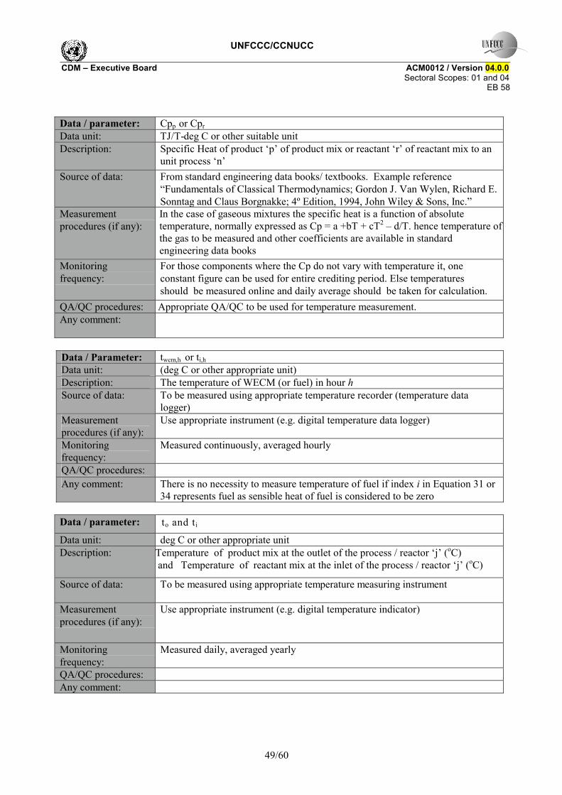
UNFCCC/CCNUCC CDM � Executive Board ACM0012 / Version 04.0.0 Sectoral Scopes: 01 and 04
EB 58
49/60
Data / parameter: Cpp or Cpr Data unit: TJ/T-deg C or other suitable unit Description: Specific Heat of product �p� of product mix or reactant �r� of reactant mix to an
unit process �n� Source of data: From standard engineering data books/ textbooks. Example reference
�Fundamentals of Classical Thermodynamics; Gordon J. Van Wylen, Richard E. Sonntag and Claus Borgnakke; 4º Edition, 1994, John Wiley & Sons, Inc.�
Measurement procedures (if any):
In the case of gaseous mixtures the specific heat is a function of absolute temperature, normally expressed as Cp = a +bT + cT2 � d/T. hence temperature of the gas to be measured and other coefficients are available in standard engineering data books
Monitoring frequency:
For those components where the Cp do not vary with temperature it, one constant figure can be used for entire crediting period. Else temperatures should be measured online and daily average should be taken for calculation.
QA/QC procedures: Appropriate QA/QC to be used for temperature measurement. Any comment:
Data / Parameter: twcm,h or ti,h Data unit: (deg C or other appropriate unit) Description: The temperature of WECM (or fuel) in hour h Source of data: To be measured using appropriate temperature recorder (temperature data
logger) Measurement procedures (if any):
Use appropriate instrument (e.g. digital temperature data logger)
Monitoring frequency:
Measured continuously, averaged hourly
QA/QC procedures: Any comment: There is no necessity to measure temperature of fuel if index i in Equation 31 or
34 represents fuel as sensible heat of fuel is considered to be zero Data / parameter: to and ti Data unit: deg C or other appropriate unit Description: Temperature of product mix at the outlet of the process / reactor �j� (oC)
and Temperature of reactant mix at the inlet of the process / reactor �j� (oC)
Source of data: To be measured using appropriate temperature measuring instrument
Measurement procedures (if any):
Use appropriate instrument (e.g. digital temperature indicator)
Monitoring frequency:
Measured daily, averaged yearly
QA/QC procedures: Any comment:
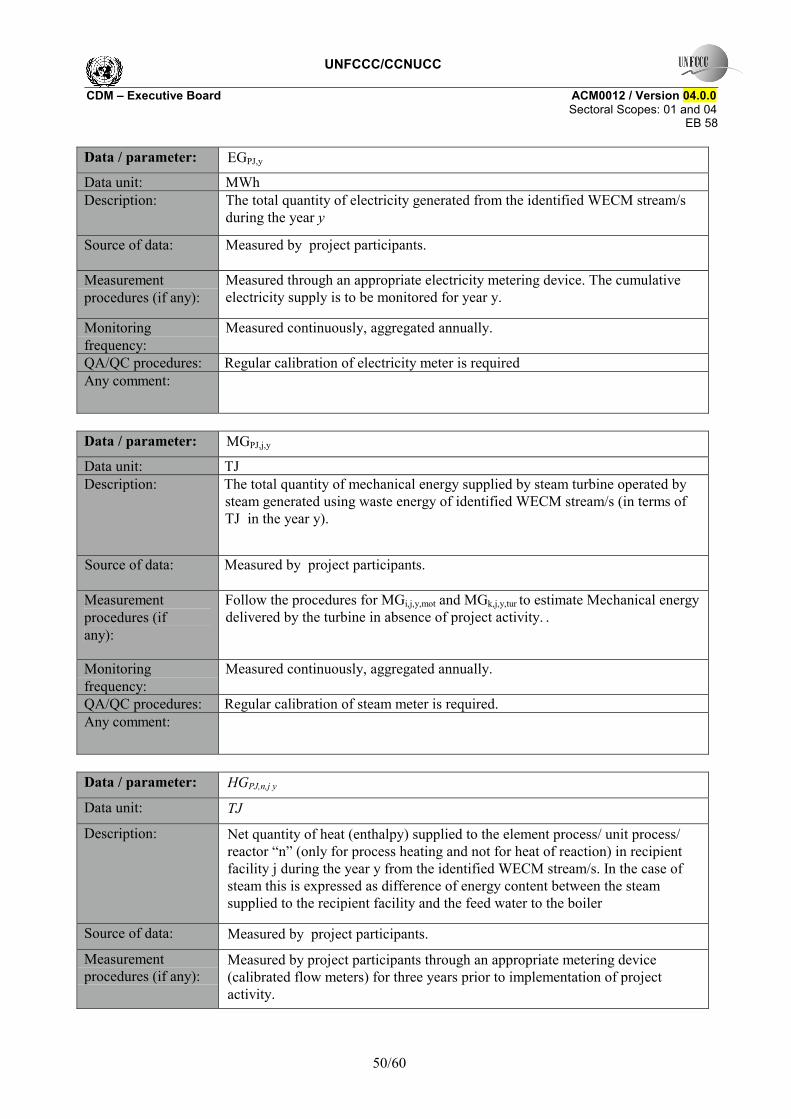
UNFCCC/CCNUCC CDM � Executive Board ACM0012 / Version 04.0.0 Sectoral Scopes: 01 and 04
EB 58
50/60
Data / parameter: EGPJ,y Data unit: MWh Description: The total quantity of electricity generated from the identified WECM stream/s
during the year y
Source of data: Measured by project participants.
Measurement procedures (if any):
Measured through an appropriate electricity metering device. The cumulative electricity supply is to be monitored for year y.
Monitoring frequency:
Measured continuously, aggregated annually.
QA/QC procedures: Regular calibration of electricity meter is required Any comment:
Data / parameter: MGPJ,j,y Data unit: TJ Description: The total quantity of mechanical energy supplied by steam turbine operated by
steam generated using waste energy of identified WECM stream/s (in terms of TJ in the year y).
Source of data: Measured by project participants.
Measurement procedures (if any):
Follow the procedures for MGi,j,y,mot and MGk,j,y,tur to estimate Mechanical energy delivered by the turbine in absence of project activity. .
Monitoring frequency:
Measured continuously, aggregated annually.
QA/QC procedures: Regular calibration of steam meter is required. Any comment:
Data / parameter: HGPJ,n,j y
Data unit: TJ
Description: Net quantity of heat (enthalpy) supplied to the element process/ unit process/ reactor �n� (only for process heating and not for heat of reaction) in recipient facility j during the year y from the identified WECM stream/s. In the case of steam this is expressed as difference of energy content between the steam supplied to the recipient facility and the feed water to the boiler
Source of data: Measured by project participants.
Measurement procedures (if any):
Measured by project participants through an appropriate metering device (calibrated flow meters) for three years prior to implementation of project activity.
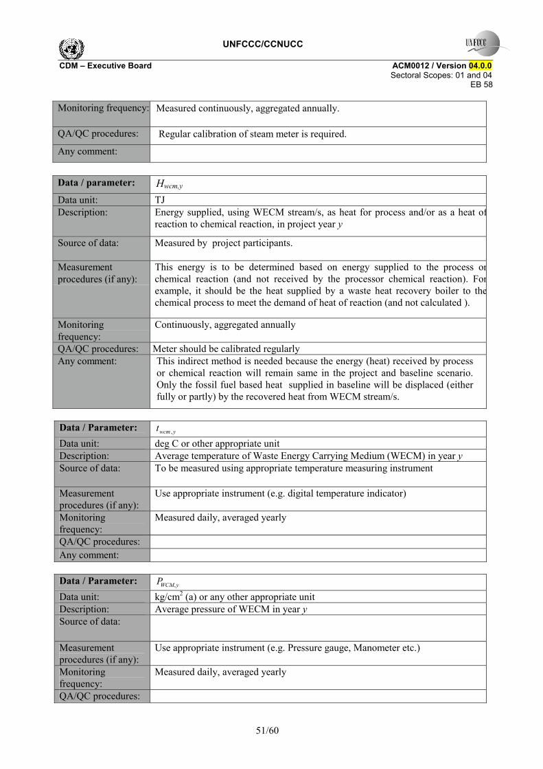
UNFCCC/CCNUCC CDM � Executive Board ACM0012 / Version 04.0.0 Sectoral Scopes: 01 and 04
EB 58
51/60
Monitoring frequency: Measured continuously, aggregated annually.
QA/QC procedures: Regular calibration of steam meter is required. Any comment: Data / parameter: Hwcm,y Data unit: TJ Description: Energy supplied, using WECM stream/s, as heat for process and/or as a heat of
reaction to chemical reaction, in project year y
Source of data: Measured by project participants.
Measurement procedures (if any):
This energy is to be determined based on energy supplied to the process orchemical reaction (and not received by the processor chemical reaction). Forexample, it should be the heat supplied by a waste heat recovery boiler to thechemical process to meet the demand of heat of reaction (and not calculated ).
Monitoring frequency:
Continuously, aggregated annually
QA/QC procedures: Meter should be calibrated regularly Any comment: This indirect method is needed because the energy (heat) received by process
or chemical reaction will remain same in the project and baseline scenario. Only the fossil fuel based heat supplied in baseline will be displaced (either fully or partly) by the recovered heat from WECM stream/s.
Data / Parameter: ywcmt , Data unit: deg C or other appropriate unit Description: Average temperature of Waste Energy Carrying Medium (WECM) in year y Source of data: To be measured using appropriate temperature measuring instrument
Measurement procedures (if any):
Use appropriate instrument (e.g. digital temperature indicator)
Monitoring frequency:
Measured daily, averaged yearly
QA/QC procedures: Any comment: Data / Parameter: yWCMP , Data unit: kg/cm2 (a) or any other appropriate unit Description: Average pressure of WECM in year y Source of data:
Measurement procedures (if any):
Use appropriate instrument (e.g. Pressure gauge, Manometer etc.)
Monitoring frequency:
Measured daily, averaged yearly
QA/QC procedures:
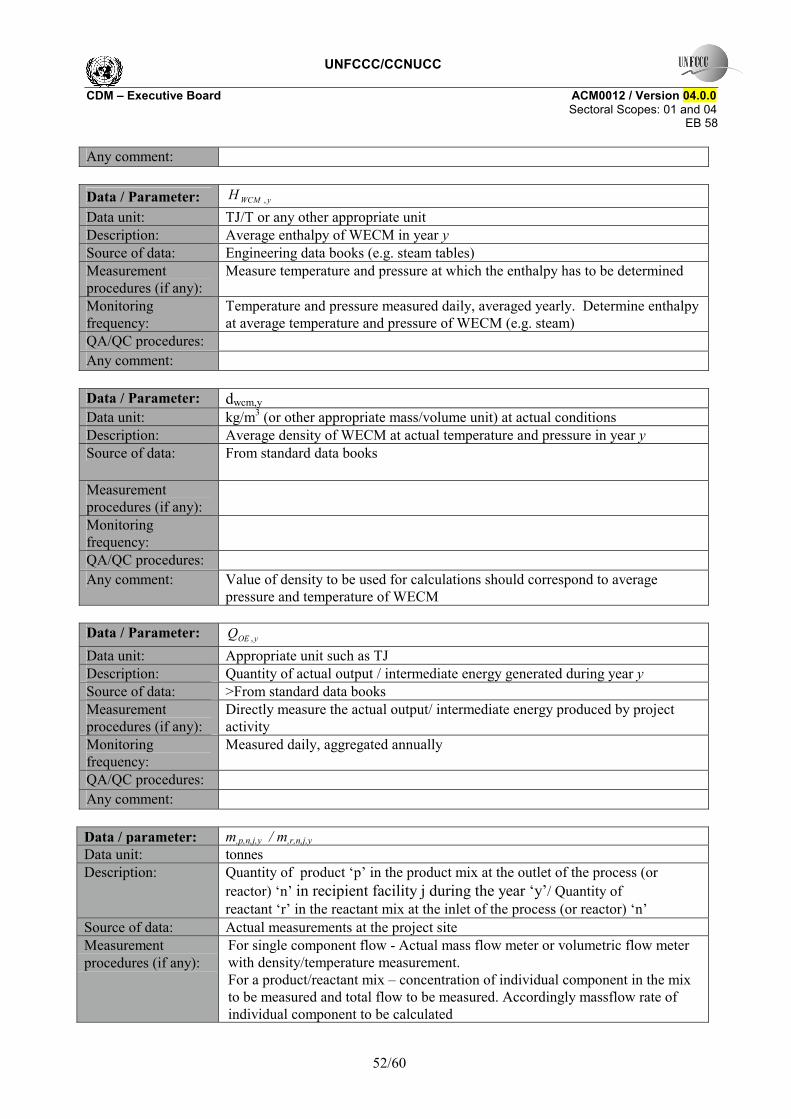
UNFCCC/CCNUCC CDM � Executive Board ACM0012 / Version 04.0.0 Sectoral Scopes: 01 and 04
EB 58
52/60
Any comment: Data / Parameter: yWCMH , Data unit: TJ/T or any other appropriate unit Description: Average enthalpy of WECM in year y Source of data: Engineering data books (e.g. steam tables) Measurement procedures (if any):
Measure temperature and pressure at which the enthalpy has to be determined
Monitoring frequency:
Temperature and pressure measured daily, averaged yearly. Determine enthalpy at average temperature and pressure of WECM (e.g. steam)
QA/QC procedures: Any comment: Data / Parameter: dwcm,y Data unit: kg/m3 (or other appropriate mass/volume unit) at actual conditions Description: Average density of WECM at actual temperature and pressure in year y Source of data: From standard data books
Measurement procedures (if any):
Monitoring frequency:
QA/QC procedures: Any comment: Value of density to be used for calculations should correspond to average
pressure and temperature of WECM Data / Parameter: yOEQ , Data unit: Appropriate unit such as TJ Description: Quantity of actual output / intermediate energy generated during year y Source of data: >From standard data books Measurement procedures (if any):
Directly measure the actual output/ intermediate energy produced by project activity
Monitoring frequency:
Measured daily, aggregated annually
QA/QC procedures: Any comment: Data / parameter: m,p,n,j,y / m,r,n,j,y Data unit: tonnes Description: Quantity of product �p� in the product mix at the outlet of the process (or
reactor) �n� in recipient facility j during the year �y�/ Quantity of reactant �r� in the reactant mix at the inlet of the process (or reactor) �n�
Source of data: Actual measurements at the project site Measurement procedures (if any):
For single component flow - Actual mass flow meter or volumetric flow meter with density/temperature measurement. For a product/reactant mix � concentration of individual component in the mix to be measured and total flow to be measured. Accordingly massflow rate of individual component to be calculated
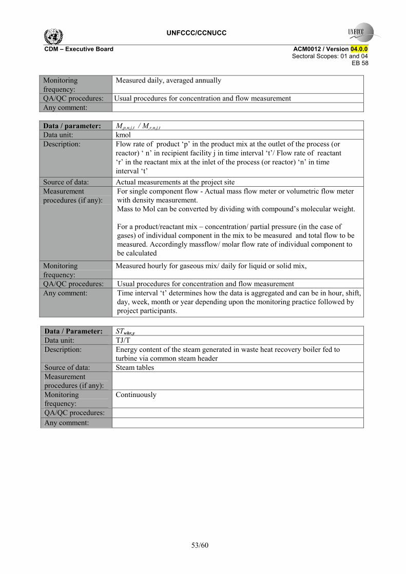
UNFCCC/CCNUCC CDM � Executive Board ACM0012 / Version 04.0.0 Sectoral Scopes: 01 and 04
EB 58
53/60
Monitoring frequency:
Measured daily, averaged annually
QA/QC procedures: Usual procedures for concentration and flow measurement Any comment: Data / parameter: M,p,n,j,t / M,r,n,j,t Data unit: kmol Description: Flow rate of product �p� in the product mix at the outlet of the process (or
reactor) � n� in recipient facility j in time interval �t�/ Flow rate of reactant �r� in the reactant mix at the inlet of the process (or reactor) �n� in time interval �t�
Source of data: Actual measurements at the project site Measurement procedures (if any):
For single component flow - Actual mass flow meter or volumetric flow meter with density measurement. Mass to Mol can be converted by dividing with compound�s molecular weight.
For a product/reactant mix � concentration/ partial pressure (in the case of gases) of individual component in the mix to be measured and total flow to be measured. Accordingly massflow/ molar flow rate of individual component to be calculated
Monitoring frequency:
Measured hourly for gaseous mix/ daily for liquid or solid mix,
QA/QC procedures: Usual procedures for concentration and flow measurement Any comment: Time interval �t� determines how the data is aggregated and can be in hour, shift,
day, week, month or year depending upon the monitoring practice followed by project participants.
Data / Parameter: STwhr,y Data unit: TJ/T Description: Energy content of the steam generated in waste heat recovery boiler fed to
turbine via common steam header Source of data: Steam tables Measurement procedures (if any):
Monitoring frequency:
Continuously
QA/QC procedures: Any comment:
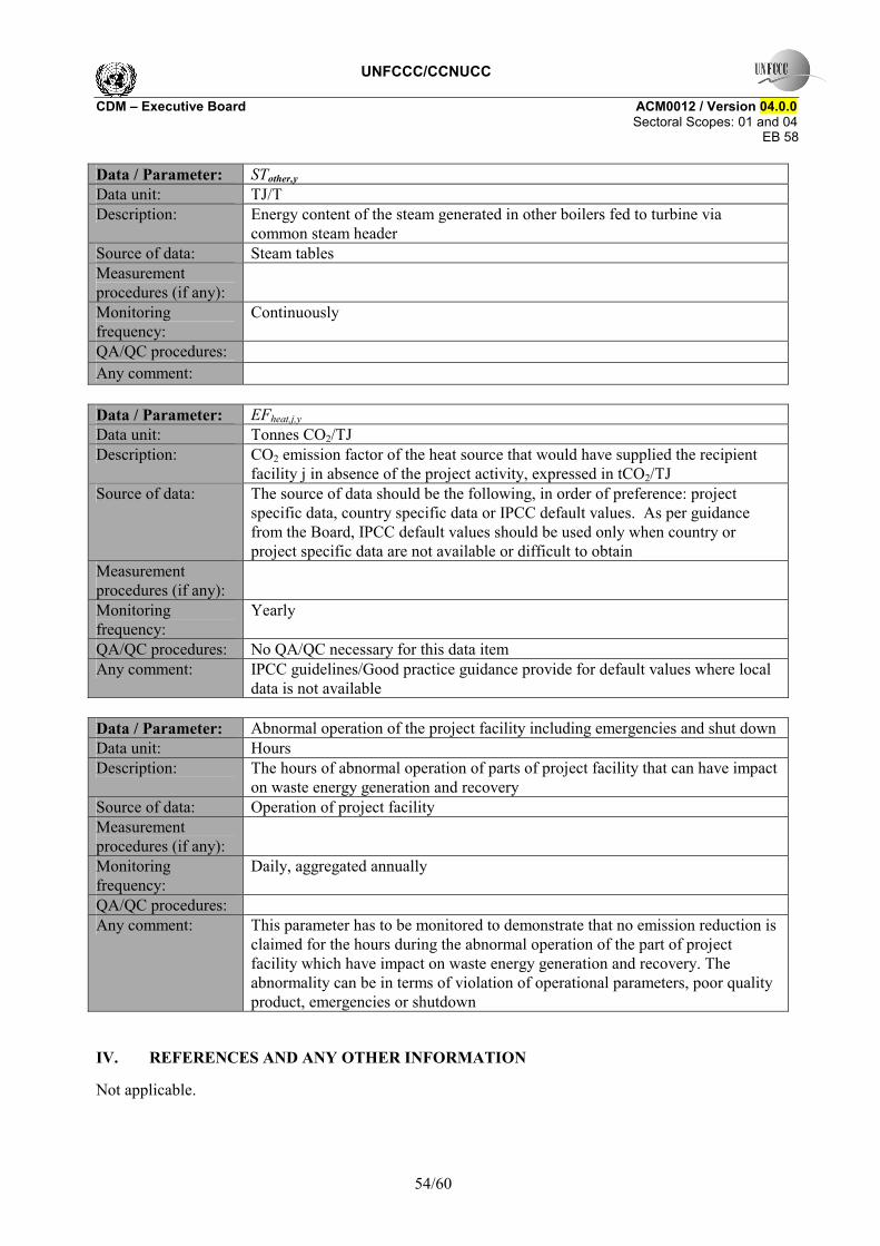
UNFCCC/CCNUCC CDM � Executive Board ACM0012 / Version 04.0.0 Sectoral Scopes: 01 and 04
EB 58
54/60
Data / Parameter: STother,y Data unit: TJ/T Description: Energy content of the steam generated in other boilers fed to turbine via
common steam header Source of data: Steam tables Measurement procedures (if any):
Monitoring frequency:
Continuously
QA/QC procedures: Any comment: Data / Parameter: EFheat,j,y Data unit: Tonnes CO2/TJ Description: CO2 emission factor of the heat source that would have supplied the recipient
facility j in absence of the project activity, expressed in tCO2/TJ Source of data: The source of data should be the following, in order of preference: project
specific data, country specific data or IPCC default values. As per guidance from the Board, IPCC default values should be used only when country or project specific data are not available or difficult to obtain
Measurement procedures (if any):
Monitoring frequency:
Yearly
QA/QC procedures: No QA/QC necessary for this data item Any comment: IPCC guidelines/Good practice guidance provide for default values where local
data is not available Data / Parameter: Abnormal operation of the project facility including emergencies and shut down Data unit: Hours Description: The hours of abnormal operation of parts of project facility that can have impact
on waste energy generation and recovery Source of data: Operation of project facility Measurement procedures (if any):
Monitoring frequency:
Daily, aggregated annually
QA/QC procedures: Any comment: This parameter has to be monitored to demonstrate that no emission reduction is
claimed for the hours during the abnormal operation of the part of project facility which have impact on waste energy generation and recovery. The abnormality can be in terms of violation of operational parameters, poor quality product, emergencies or shutdown
IV. REFERENCES AND ANY OTHER INFORMATION
Not applicable.
UNFCCC/CCNUCC CDM � Executive Board ACM0012 / Version 04.0.0 Sectoral Scopes: 01 and 04
EB 58
55/60
Annex 1: Assessment of extent of use of WECM and determination of baseline practice factor for CDM project activity implemented in Greenfield facilities using reference waste energy generating facility (or �reference facility� for the purpose of this annex) and manufacturer�s specifications. Option-1: Assessment of other existing facilities
1. The Greenfield (or new) facility generating the WECM used in the CDM project activity should be categorised based on following criteria applicable to project facility: (i) industry sector; (ii) product manufactured, its specifications and applications; (iii) production capacity ; (iv) quality of raw material used; (v) process flow or technology type; (vi) configuration of the facility; (v) facilities implemented in previous 10 years.
2. Based on the literature from the recognised sources, or from a survey in the relevant industry sector, those facilities should be listed which follow the criteria mentioned above. The selected facilities can vary by +/-10% in terms of capacity of the facility as compared to the proposed facility under CDM.
3. These facilities should not cover those which are already registered (or under validation) under CDM for waste energy recovery projects from the same source that is recovered under the proposed project under CDM.
4. The difference between the project facility and the selected facilities would be the use of waste energy from the source that is recovered under proposed project activity.
5. The facilities identified above should be studied for the use of waste energy. The following can be the possible uses of waste energy by these facilities: (i) the waste energy completely used, (ii) waste energy partially used, (iii) waste energy not used but incinerated, flared or released to atmosphere.
6. Analyse the practice of more than 75% facilities in the list. For example following situations can apply: (i) if more than half of the facilities do not use waste energy, it can be decided that the proposed Greenfield facility also would have wasted the energy in the absence of waste energy recovery CDM project; (ii) if more than half of the facilities use the waste energy partially, the baseline emissions can be capped using the most conservative baseline practice factor (fpractice) based on the percentage of waste energy used in the baseline; for example a 50% usage of waste energy in these facilities results in to fpractice of 0.5; (iii) if more than 50% of the facilities recover the waste energy fully, the methodology is not applicable as it cannot be demonstrated that waste energy would not have been recovered in the absence of CDM project. Use operational information or manufacturer�s specification of the facilities.
7. In case none of the above practices are followed by more than 50% of facilities, the most conservative practice decides the baseline emissions practice factor (fpractice).
For the use of option-1, it is necessary that at least five facilities are analysed to arrive at �reference facility� practice. Option-2: Assessment of alternative design of the project facility: This option is to be used if the project participants are not able to arrive at five facilities of similar type as the Greenfield project facility. The manufacturer of the project facility will be invited to submit an alternative design including the usage of WECM that is recovered under project. The project participants have to demonstrate through investment analysis that the use (or no use) of WECM/s of such alternative design would have been the baseline scenario for the waste energy generated in the Greenfield facility. The alternative design provides the value of factor �fpractice� that is referred in option-1 above.

UNFCCC/CCNUCC CDM � Executive Board ACM0012 / Version 04.0.0 Sectoral Scopes: 01 and 04
EB 58
56/60
Annex 2: Assessment of extent of use of WECM in the existing facility
It shall be demonstrated that the waste energy utilized in the project activity was flared or released into the atmosphere or remained unutilised in the absence of the project activity at the existing or new facility20 by either one of the following methods21. The DoE should supplement the analysis prescribed by following methods through the on-site checks prior to project implementation to confirm that no equipment for waste energy recovery and utilisation had been installed on the specific WECM stream (that is recovered under the project activity) prior to the implementation of the CDM project activity. In case of the project activities improving the energy recovery from the already existing WECM stream/s, the DoE will make the on-site checks to confirm the above with respect to unrecovered stream or energy.
• By direct measurements of the amount of the waste energy produced for at least three years prior to the start of the project activity;
• Providing an energy balance of the relevant sections of the facility to prove that the waste energy, that is recovered in project activity, was not a source of energy before the implementation of the project activity. For the energy balance applicable process parameters are required. The energy balance must demonstrate that the waste energy was not used and also provide conservative estimations of the amount of waste energy released.
• Energy bills (electricity, fossil fuel) to demonstrate that all the energy required for the process (e.g. based on specific energy consumption specified by the manufacturer) has been procured commercially. Project participants are required to demonstrate through the financial documents (e.g. balance sheets, profit and loss statement) that no energy was generated by waste energy and sold to other facilities and/or the grid. The bills and financial statements should be audited by competent authorities.
• Process plant manufacturer�s commissioning report from the facility could be used as an estimate of the quantity and energy content of the waste energy produced for the rated plant capacity/per unit of product produced.
• For the project activity, improving energy efficiency of existing waste heat recovery equipment, the demonstration of low energy recovery of WECM steam/s should be done by estimating the energy efficiency of the electricity and/ or heat generation equipment/s and demonstrating the amount of heat and/ or captive electricity generated for at least three years prior to the start of the project activity;
20 Facilities where the commercial production had began at the time when the Project Activity is submitted for
validation. 21 If it cannot be demonstrated through procedures listed in sub-bullets that the WECM has been flared/combusted or
released into atmosphere or the pressure has been wasted in absence of project activity, the project proponent can propose a procedure for indirect measurements (in the context of specific industrial applications) as a revision to the methodology.
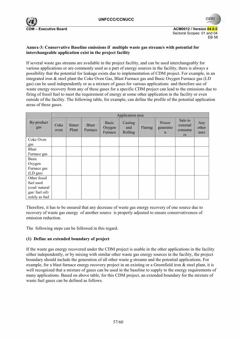
UNFCCC/CCNUCC CDM � Executive Board ACM0012 / Version 04.0.0 Sectoral Scopes: 01 and 04
EB 58
57/60
Annex-3: Conservative Baseline emissions if multiple waste gas stream/s with potential for interchangeable application exist in the project facility If several waste gas streams are available in the project facility, and can be used interchangeably for various applications or are commonly used as a part of energy sources in the facility, there is always a possibility that the potential for leakage exists due to implementation of CDM project. For example, in an integrated iron & steel plant the Coke Oven Gas, Blast Furnace gas and Basic Oxygen Furnace gas (LD gas) can be used independently or as a mixture of gases for various applications and therefore use of waste energy recovery from any of these gases for a specific CDM project can lead to the emissions due to firing of fossil fuel to meet the requirement of energy at some other application in the facility or even outside of the facility. The following table, for example, can define the profile of the potential application areas of these gases.
Application area
By-product gas Coke
oven Sinter Plant
Blast Furnace
Basic Oxygen Furnace
Casting and
Rolling Flaring
Power generatio
n
Sale to external consume
rs
Any other uses
Coke Oven gas
Blast Furnace gas
Basic Oxygen Furnace gas (LD gas)
Other fossil fuel used (coal/ natural gas/ fuel oil) solely as fuel
Therefore, it has to be ensured that any decrease of waste gas energy recovery of one source due to recovery of waste gas energy of another source is properly adjusted to ensure conservativeness of emission reduction. The following steps can be followed in this regard. (1) Define an extended boundary of project If the waste gas energy recovered under the CDM project is usable in the other applications in the facility either independently, or by mixing with similar other waste gas energy sources in the facility, the project boundary should include the generation of all other waste g streams and the potential applications. For example, for a blast furnace energy recovery project in an existing or a Greenfield iron & steel plant, it is well recognized that a mixture of gases can be used in the baseline to supply to the energy requirements of many applications. Based on above table, for this CDM project, an extended boundary for the mixture of waste fuel gases can be defined as follows.
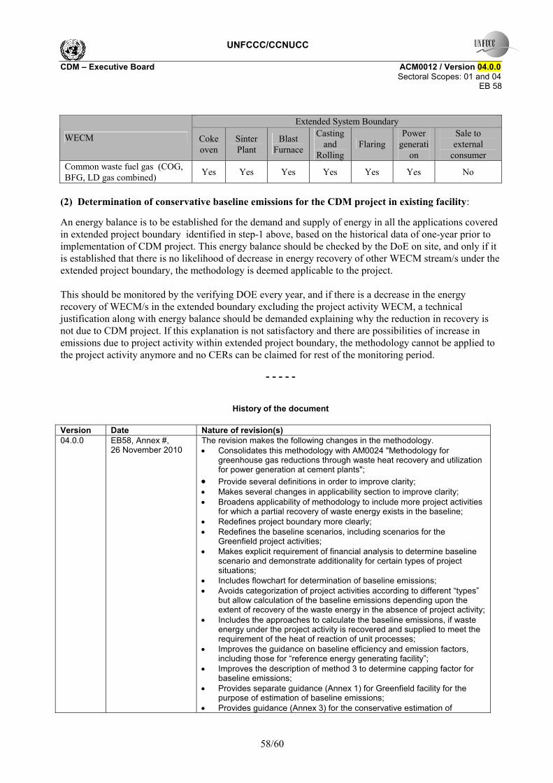
UNFCCC/CCNUCC CDM � Executive Board ACM0012 / Version 04.0.0 Sectoral Scopes: 01 and 04
EB 58
58/60
Extended System Boundary
WECM Coke oven
Sinter Plant
Blast Furnace
Casting and
Rolling Flaring
Power generati
on
Sale to external
consumer Common waste fuel gas (COG, BFG, LD gas combined) Yes Yes Yes Yes Yes Yes No
(2) Determination of conservative baseline emissions for the CDM project in existing facility:
An energy balance is to be established for the demand and supply of energy in all the applications covered in extended project boundary identified in step-1 above, based on the historical data of one-year prior to implementation of CDM project. This energy balance should be checked by the DoE on site, and only if it is established that there is no likelihood of decrease in energy recovery of other WECM stream/s under the extended project boundary, the methodology is deemed applicable to the project. This should be monitored by the verifying DOE every year, and if there is a decrease in the energy recovery of WECM/s in the extended boundary excluding the project activity WECM, a technical justification along with energy balance should be demanded explaining why the reduction in recovery is not due to CDM project. If this explanation is not satisfactory and there are possibilities of increase in emissions due to project activity within extended project boundary, the methodology cannot be applied to the project activity anymore and no CERs can be claimed for rest of the monitoring period.
- - - - -
History of the document
Version Date Nature of revision(s) 04.0.0 EB58, Annex #,
26 November 2010 The revision makes the following changes in the methodology. • Consolidates this methodology with AM0024 "Methodology for
greenhouse gas reductions through waste heat recovery and utilization for power generation at cement plants";
• Provide several definitions in order to improve clarity; • Makes several changes in applicability section to improve clarity; • Broadens applicability of methodology to include more project activities
for which a partial recovery of waste energy exists in the baseline; • Redefines project boundary more clearly; • Redefines the baseline scenarios, including scenarios for the
Greenfield project activities; • Makes explicit requirement of financial analysis to determine baseline
scenario and demonstrate additionality for certain types of project situations;
• Includes flowchart for determination of baseline emissions; • Avoids categorization of project activities according to different �types�
but allow calculation of the baseline emissions depending upon the extent of recovery of the waste energy in the absence of project activity;
• Includes the approaches to calculate the baseline emissions, if waste energy under the project activity is recovered and supplied to meet the requirement of the heat of reaction of unit processes;
• Improves the guidance on baseline efficiency and emission factors, including those for �reference energy generating facility�;
• Improves the description of method 3 to determine capping factor for baseline emissions;
• Provides separate guidance (Annex 1) for Greenfield facility for the purpose of estimation of baseline emissions;
• Provides guidance (Annex 3) for the conservative estimation of
UNFCCC/CCNUCC CDM � Executive Board ACM0012 / Version 04.0.0 Sectoral Scopes: 01 and 04
EB 58
59/60
baseline emissions where multiple waste gas streams exist in the project facilities with potential for interchangeability of application;
• Revises project emission section to remove some sources of emissions;
• Provides explicit situations to calculate project emissions due to combustion of auxiliary fuel along with waste energy;
• Refers the tools �Tool to calculate baseline, project and/or leakage emissions from electricity consumption�, �Tool to determine the baseline efficiency of thermal or electric energy generation systems� and �Tool to determine the remaining lifetime of equipment�;
• Includes the monitoring requirements for return condensate in the configuration of extraction cum condensing turbine;
• Deletes/ add/ changes several parameters in monitoring section. • Modifies the structure of methodology and carries out several textual
changes to improve clarity of methodology. 03.2 EB 51, Annex 10
04 December 2009 Editorial revision: • The editorial revision in the description text of Equation (1h) in the
section of baseline emissions (Case 1 and Case 2 of Method-3 for capping of baseline emissions).
03.1 EB 44, Annex 13 28 November 2008
Editorial revision: • The parameter HGj,y further described; • Editorial changes carried out in Equation 1b).
03 EB 41, Annex 6 02 August 2008
Revision to incorporate the following changes: • Inclusion of project activity under applicability of methodology, which is
based on replacement of electrical or steam-driven drives in baseline with steam turbine, which is driven by steam recovered from waste energy;
• Inclusion of Type-2 project activities where part of waste gas energy was recovered in baseline for the purpose of power generation and project intends to improve utilisation of waste gas energy with high efficiency heat recovery equipment for the purpose of power generation;
• Clarity provided on fcap calculations where project proponents do not have baseline data of waste energy for three years prior to implementation of project activity;
• Clarity provided in waste gas streams. Applicability condition added for Type-1 activities to cover scenario where in baseline there are other non-CDM projects recovering waste energy and as a result of CDM project, their energy generation is reduced and diverted to CDM project;
• Consistency is provided in use of terms waste gas/heat/pressure. In many instances this is replaced by the common term �waste energy�;
• Provided new capping procedure (Method-3) for waste energy, further elaborated Method-1;
• Monitoring tables amended to incorporate parameters of new and modified capping procedures;
• Added new definitions of waste energy and waste energy carrying medium. Modified definition of cogeneration;
• Added new applicability condition for waste pressure recovery projects. 02 EB 35, Para 24
19 October 2007 Revision to incorporate the use of the �Tool to calculate the emission factor for an electricity system�.

UNFCCC/CCNUCC CDM � Executive Board ACM0012 / Version 04.0.0 Sectoral Scopes: 01 and 04
EB 58
60/60
01 EB 32, Annex 8
22 June 2007 Initial adoption.
Decision Class: Regulatory Document Type: Standard Business Function: Methodology