Embed Size (px)
Citation preview

THINK LEFT AND THINK RIGHTAND THINK LOW AND THINK HIGH. OH, THE THINKS YOU CAN
THINK UP IF ONLY YOU TRY!
—Dr. Seuss
2020IDEAS2
AWARDS


2018 AWARD WINNERSINNOVATIVE DESIGN in ENGINEERING and ARCHITECTURE with STRUCTURAL STEEL
2020 AWARD WINNERSINNOVATIVE DESIGN in ENGINEERING and ARCHITECTURE with STRUCTURAL STEEL
© AISC 2020
by
American Institute of Steel Construction
ISBN 978-1-56424-050-7
All rights reserved. This book or any part thereof must not be reproduced in any form without the
written permission of the publisher. The AISC logo is a registered trademark of AISC.
Printed in the United States of America

ContentsABOUT THE COMPETITION 4
PROJECTS LESS THAN $15 MILLION NATIONAL: Hinterland Brewery, Green Bay, Wis. 10 MERIT: Marvin Gaye Recreation Center, Washington 14
PROJECTS $15–$75 MILLION NATIONAL: Mori Hosseini Student Union—Embry-Riddle Aeronautical University, Daytona Beach, Fla. 18 MERIT: Canyon View High School, Waddell, Ariz. 22
AISC will not present any 2020 awards in the $75 million to $200 million category.
PROJECTS GREATER THAN $200 MILLION NATIONAL: Wilshire Grand Center, Los Angeles 26 MERIT: Sutter Health CPMC Van Ness Campus—Viscous Wall Dampers, San Francisco 30
SCULPTURE/INSTALLATION/NON-BUILDING STRUCTURE NATIONAL: Hartsfield-Jackson Atlanta International Airport Modernization, Atlanta 34 MERIT: Belmont Gateway Canopy—Chicago Transit Authority, Chicago 38 MERIT: Little Charlotte Office Monumental Stair, Charlotte, N.C. 42
2021 CALL FOR ENTRIES 47

4
Eligibility Requirements
The competition is open to all building types, sizes, and costs, as long as a significant portion of the framing system is steel (wide-flange shapes or hollow structural sections), the project is located in the U.S., and the steel fabrication took place in the U.S. Pedestrian bridges entered in the competition must be an intrinsic part of a building, not stand-alone structures. New buildings and renovations are eligible. To qualify for this year’s competition, projects must have been completed between 2017 and the end of 2019.
Benefits of SteelThe selection of structural steel for a building’s framing system brings numerous benefits to a project, including cost-effectiveness, speed of construction, pleasing aesthetics, future adaptability, and ease of design. The winning projects showcase the beauty and usefulness of structural steel in building projects of every size and description. The design and construction industry increasingly recognizes the value of coordination, collaboration, and teamwork in the successful accomplishment of a project’s program. In active support of this trend, the IDEAS² Awards recognize excellence and innovation in the use of structural steel throughout the development and construction of a single project.
The Innovative Design in Engineering and Architecture with Structural Steel (IDEAS²) Awards recognize excellence and innovation in the use of structural steel on building projects across the country. They are the highest honor bestowed on building projects by the U.S. structural steel industry. Conducted annually by the American Institute of Steel Construction (AISC), the IDEAS² Awards program honors the innovative use of structural steel in:
• the accomplishment of the structure’s program,• the expression of architectural intent,• the application of design approaches to the structural system, and• the use of productivity-enhancing construction methods.
2020IDEAS2
AWARDS

5
The American Institute of Steel Construction (AISC) established the Architectural Awards of Excellence (A.A.E.) in 1960 to recognize and honor outstanding architectural design in structural steel and to encourage further exploration of the many aesthetic possibilities that are inherent in steel construction. The aesthetic appearance of the buildings was the primary factor used in judging projects. Any type of building framed with structural steel was eligible.
During the 1980s, AISC used various magazines to advertise steel’s advantages and to publicize its award programs. For several years, the winners of AISC’s Architectural Awards of Excellence were featured in a special section of Building Design + Construction magazine, which also ran an annual Steel Supplement. These awards evolved into the I.D.E.A.S. (Innovative Design and Excellence in Architecture with Steel) Awards.
During the same period, AISC presented the Engineering Awards of Excellence (E.A.E.) annually, recognizing engineering excellence and innovation in steel-framed buildings.
In 2006, AISC joined the two previously separate architecture and structural engineering awards programs into one: the IDEAS² Awards. This awards program was designed to recognize all team members responsible for excellence and innovation in a project’s use of structural steel.
Awards for each winning project are presented to the project team members involved in the design and construction of the structural framing system, including the architect, structural engineer of record, general contractor, owner, and AISC member fabricator, erector, detailer, and bender-roller. Specialty consultants and contractors are recognized at the discretion of the architect and structural engineer of record. Any member of the project team may submit a project for consideration.
History

6
Judging Criteria• creative solutions to the project’s program requirements; • applications of innovative design approaches in areas such as connections,
gravity systems, lateral load-resisting systems, fire protection, and blast protection;
• the aesthetic impact of the project, particularly in the coordination of structural steel elements with other materials;
• innovative uses of architecturally exposed structural steel (AESS); • advancements in the use of structural steel, either technically or in the
architectural expression; and • the use of innovative design and construction methods such as 3D building
models, interoperability, early integration of steel fabricators, alternative methods of project delivery, and sustainability considerations.
A panel of design and construction industry professionals judge the entries in four categories according to constructed value in U.S. dollars: less than $15 million, $15 million to $75 million, $75 million to $200 million, and greater than $200 million. National and Merit awards, the Presidential Award of Excellence, and jury recognition for art installations, sculptures, and non-building structures are bestowed at the judges’ discretion. The judges consider each project’s use of structural steel from both an architectural and structural engineering perspective with an emphasis on:
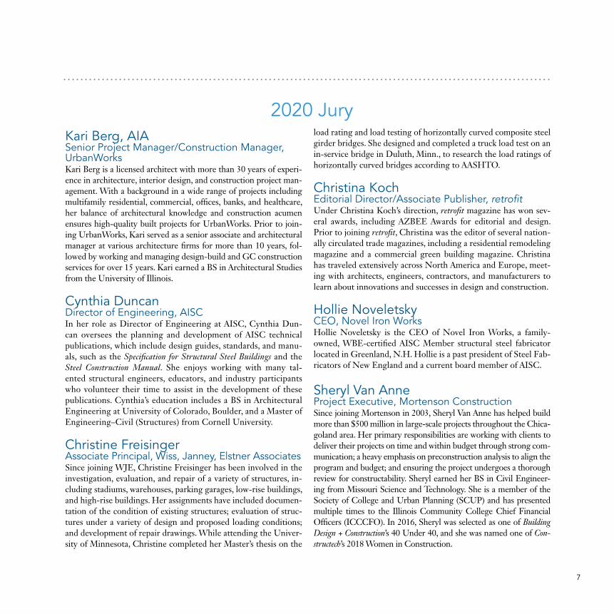
The 2020 judging panel, from left: Cynthia Duncan, Hollie Noveletsky, Christine Freisinger, Christina Koch, Kari Berg, and Sheryl Van Anne
7
2020 JuryKari Berg, AIA Senior Project Manager/Construction Manager, UrbanWorks Kari Berg is a licensed architect with more than 30 years of experi-ence in architecture, interior design, and construction project man-agement. With a background in a wide range of projects including multifamily residential, commercial, offices, banks, and healthcare, her balance of architectural knowledge and construction acumen ensures high-quality built projects for UrbanWorks. Prior to join-ing UrbanWorks, Kari served as a senior associate and architectural manager at various architecture firms for more than 10 years, fol-lowed by working and managing design-build and GC construction services for over 15 years. Kari earned a BS in Architectural Studies from the University of Illinois.
Cynthia DuncanDirector of Engineering, AISC In her role as Director of Engineering at AISC, Cynthia Dun-can oversees the planning and development of AISC technical publications, which include design guides, standards, and manu-als, such as the Specification for Structural Steel Buildings and the Steel Construction Manual. She enjoys working with many tal-ented structural engineers, educators, and industry participants who volunteer their time to assist in the development of these publications. Cynthia’s education includes a BS in Architectural Engineering at University of Colorado, Boulder, and a Master of Engineering–Civil (Structures) from Cornell University.
Christine FreisingerAssociate Principal, Wiss, Janney, Elstner AssociatesSince joining WJE, Christine Freisinger has been involved in the investigation, evaluation, and repair of a variety of structures, in-cluding stadiums, warehouses, parking garages, low-rise buildings, and high-rise buildings. Her assignments have included documen-tation of the condition of existing structures; evaluation of struc-tures under a variety of design and proposed loading conditions; and development of repair drawings. While attending the Univer-sity of Minnesota, Christine completed her Master’s thesis on the
load rating and load testing of horizontally curved composite steel girder bridges. She designed and completed a truck load test on an in-service bridge in Duluth, Minn., to research the load ratings of horizontally curved bridges according to AASHTO.
Christina KochEditorial Director/Associate Publisher, retrofit Under Christina Koch’s direction, retrofit magazine has won sev-eral awards, including AZBEE Awards for editorial and design. Prior to joining retrofit, Christina was the editor of several nation-ally circulated trade magazines, including a residential remodeling magazine and a commercial green building magazine. Christina has traveled extensively across North America and Europe, meet-ing with architects, engineers, contractors, and manufacturers to learn about innovations and successes in design and construction.
Hollie NoveletskyCEO, Novel Iron WorksHollie Noveletsky is the CEO of Novel Iron Works, a family-owned, WBE-certified AISC Member structural steel fabricator located in Greenland, N.H. Hollie is a past president of Steel Fab-ricators of New England and a current board member of AISC.
Sheryl Van AnneProject Executive, Mortenson ConstructionSince joining Mortenson in 2003, Sheryl Van Anne has helped build more than $500 million in large-scale projects throughout the Chica-goland area. Her primary responsibilities are working with clients to deliver their projects on time and within budget through strong com-munication; a heavy emphasis on preconstruction analysis to align the program and budget; and ensuring the project undergoes a thorough review for constructability. Sheryl earned her BS in Civil Engineer-ing from Missouri Science and Technology. She is a member of the Society of College and Urban Planning (SCUP) and has presented multiple times to the Illinois Community College Chief Financial Officers (ICCCFO). In 2016, Sheryl was selected as one of Building Design + Construction’s 40 Under 40, and she was named one of Con-structech’s 2018 Women in Construction.

8
Nine structural steel projects have earned a 2020 IDEAS² Award. Our panel of design and construction industry professionals judged the entries in four categories, according to their constructed value in U.S. dollars: projects costing less than $15 million, projects costing between $15 million and $75 million, projects costing $75 million to $200 million, and projects costing more than $200 million. The judges awarded National and Merit honors in all categories except $75 million to $200 million. They also selected National and Merit winners in a fifth category that recognizes sculptures, art installations, and other non-building structures.
This year’s winners include a public transit canopy that evokes a waterfall—or perhaps a giant blue butterfly wing. An office stairwell that appears to defy gravity. A supertall mixed-use tower with a hotel lobby at the top. A cozy Wisconsin brewery clad in weathering steel. A hospital boasting the country’s first use of viscous wall dampers.
The IDEAS² Award program recognizes the importance of teamwork, coordination, and collaboration in fostering successful projects. Awards will be presented to members of the project teams throughout the year. The winning projects are also featured in the May 2020 issue of AISC’s Modern Steel Construction magazine.
2020 Winners
We celebrate these projects and appreciate the savvy, creative people behind them for showcasing the beauty and usefulness of structural steel.
Our hearty congratulations to the award-winning teams for a great compilation of excellent solutions!
—Charles J. Carter, SE, PE, PhD, president of AISC

9
Think left and think right and think low and think high.
Oh, the thinks you can think up if only you try!
—Dr. Seuss

Rafael Gamo
10
Rafael Gamo
11
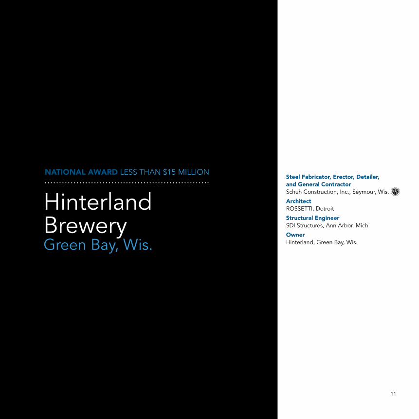
NATIONAL AWARD LESS THAN $15 MILLION
Hinterland BreweryGreen Bay, Wis.
Steel Fabricator, Erector, Detailer, and General ContractorSchuh Construction, Inc., Seymour, Wis.
ArchitectROSSETTI, Detroit
Structural EngineerSDI Structures, Ann Arbor, Mich.
OwnerHinterland, Green Bay, Wis.

12
WHETHER OR NOT you’re a Green Bay Packers fan, you can’t deny that the new Hinterland Brewery has a primo location.
It also has a primo structural steel design. Inspired by the industrial architecture of the Great Lakes region, the restaurant and functioning brewery is the cornerstone of a mixed-use development within a stadium entertainment district—and it sits right across the street from the Packers’ storied stadium, Lambeau Field. The simple palette of materials—steel, brick, and glass—was selected to express careful workmanship and highlight the detailed process of the building’s construction. Like the quality grains, hops, and water used in the brewing process, these fundamental building materials were the ingredients used to shape the experience throughout—and steel was the predominant material used to achieve these design goals.
The building is organized by a spine of structural steel frames that serve as both the primary lateral and gravity systems. The roof elements are structural steel bents fabricated from complete joint penetration (CJP) welded wide-flange sections. The framing evokes early twentieth-century factories and brings a unique form to the rooftop, giving the structure its distinctive shape and filling the interior with daylight.
The roof is a standing-seam steel roof system, with steel members and purlins dominating the expression of the interior spaces. The exposed steel aesthetic extends throughout the interior detailing of various areas, such as a mezzanine that overlooks and surrounds the brewing equipment, to express both strength and artistry. The pigmented lacquer that protects the interior steel permanently captures the industrial feel and preserves the grease pencil markings placed on the steel at the time of fabrication. Two sculptural stairways escort patrons between floors of the restaurant space, with steel plate guardrails serving as stringers to provide both support and enclosure for the stairs; wood treads complement the steel. In addition, much of the building’s exterior is clad in a raw weathering steel rain screen.
This new home for a brewery that started more than twenty years ago—and whose previous location was a few miles away in the city’s Broadway District—has allowed Hinterland to improve its quality and increase its capacity. Business has grown exponentially since the brewery moved into its new home, with much of the credit for that success going to its design and exposed steel aesthetic. And its proximity to one of the shrines of the NFL doesn’t hurt.
Hinterland has blended exposed structural steel into the design seamlessly to provide a warm, welcoming atmosphere.
—Christine Freisinger
Rossetti

Rafael Gamo
Rafael Gamo
Rafael Gamo
Jon Disbrow
Rafael Gamo
13
Hoachlander Davis Photography14

Hoachlander Davis Photography 15
MERIT AWARD LESS THAN $15 MILLION
Marvin Gaye Recreation CenterWashington
ArchitectISTUDIO Architects, Washington
Structural EngineerSimpson Gumpertz and Heger, Inc., Washington
General ContractorMCN Build, Washington
OwnerDepartment of General Services, Washington

16
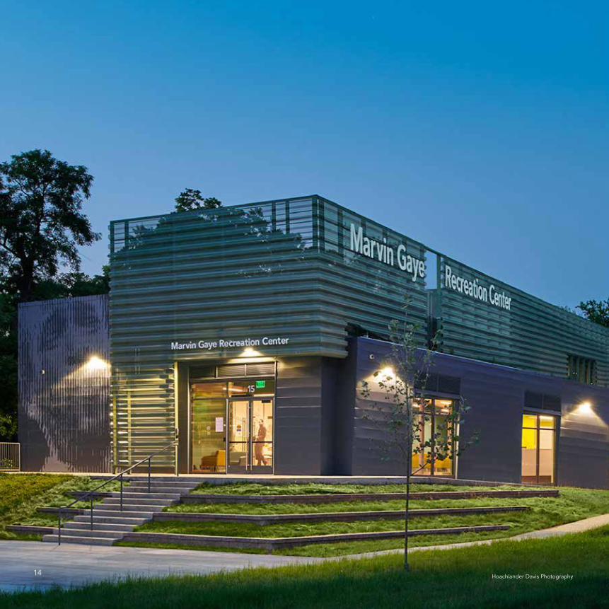
WHILE MANY of Washington’s famously grand edifices are named for prominent politicians, a new recreation center honors another American legend—and a native of the nation’s capital: singer, songwriter, producer, and one of the creators of the Motown sound, Marvin Gaye.
The new facility, the Marvin Gaye Recreation Center, is elevated above a 100-year floodplain to bring visitors into the tree canopy as steel girders, supported by angled columns, cantilever the second floor over an adjacent stream. The strength of structural steel brings the resilience needed for withstanding floodplain requirements and creates a light and tensile touch to the final design.
The location of the building itself was limited by tight constraints, as the site borders a do-not-build floodway and is located within the floodplain. The project team took one of the site’s largest challenges and turned it to an opportunity, creating a building that cantilevers into the tree canopy above the stream, offering individuals a unique vantage point to the building’s surroundings. The steel columns had to be angled in order to cantilever the balcony above the stream. While it is necessary to carry the structural loads, the angled steel is elevated beyond that duty to become a prominent design feature. The design of the columns was an iterative and collaborative effort between the architect and structural engineer, with the engineer sharing
the structurally required column angles and locations while the architect responded to coordinate site constraints, ADA clearances, and alignment to the architectural concept.
Implementing “wash and wear” materials is a necessity for a rec-reation center, and using exposed steel accomplished the structural goals while also providing a durable, long-term solution to create a low-maintenance facility. In keeping with the theme of sturdy mate-rials, the building is clad with perforated façade panels (also steel) that are designed to withstand stray soccer balls and such from the heavily used recreation fields adjacent to the building. The perfo-rated metal façade also functions as mechanical screening for the rooftop units, controls solar heat gain and glare to reduce mechani-cal loads, and creates unique views from the second floor.
One of the key coordination items for the project’s design-build team was determining how to connect the back of the screen to the building’s steel frame. The solution came in the form of steel outriggers, welded to the structural beams, that protrude from the building to accept the screen’s support clips (with thermal break elements separating the outriggers from the screen).
In addition to its protective and shading functions, the screen also gives the building its identity, drawing the eye and creating a neighborhood icon—especially at night, when the building glows like a lantern in a previously underserved neighborhood in the far eastern reaches of the District.
1. locationbetween the floodway + athletic field
2. plinthraised above the 100 year floodplain
3. cantileverto get closer to the stream
4. balconypush in the exterior to create and outdoor space
5. pathup through the building to a vantage point
6. artadd expression to the exterior and interior
7. ventilationautomated natural ventilation throughout building
8. screencontrol solar gain and glare while framing views
The Marvin Gaye Recreation Center celebrates structural ingenuity as it cantilevers above an adjacent stream into the tree canopy by using
angled steel columns to make use of a challenging site. —Christine Freisinger

ISTUDIO Architects
17
Hoachlander Davis Photography
Hoachlander Davis Photography
Hoachlander Davis Photography
Hoachlander Davis Photography

Brad Feinknopf
18

19
NATIONAL AWARD $15 MILLION TO $75 MILLION
Mori Hosseini Student UnionEmbry-Riddle Aeronautical University Daytona Beach, Fla.
Steel TeamFabricatorsSteel, LLC, Scottdale, Ga. Greiner Industries, Inc., Mount Joy, Pa. (also served as bender/roller) Fabco Metal Products, LLC, Daytona Beach, Fla.
Detailer, Connection Designer, and Erection EngineerMcGill Engineering, Inc., Tampa, Fla.
ErectorSuperior Rigging and Erecting Company, Atlanta
Architectikon.5 architects, New York
Structural EngineerThornton Tomasetti, Newark, N.J.
General ContractorBarton Malow Company, Orlando, Fla.
OwnerEmbry-Riddle Aeronautical University, Daytona Beach, Fla.
20
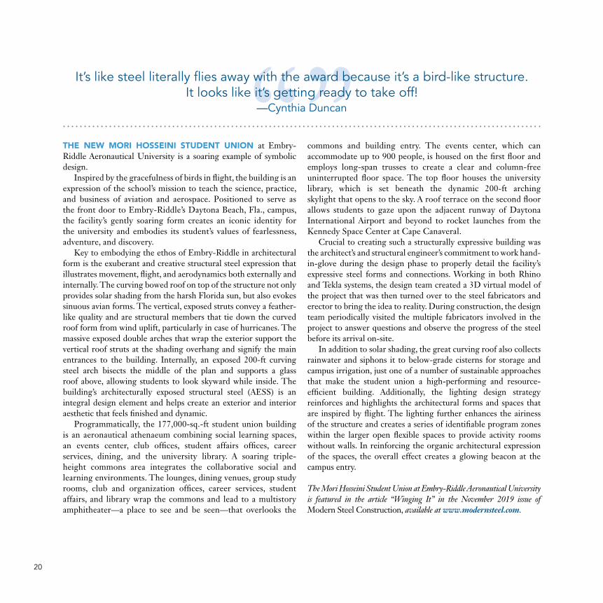
THE NEW MORI HOSSEINI STUDENT UNION at Embry-Riddle Aeronautical University is a soaring example of symbolic design.
Inspired by the gracefulness of birds in flight, the building is an expression of the school’s mission to teach the science, practice, and business of aviation and aerospace. Positioned to serve as the front door to Embry-Riddle’s Daytona Beach, Fla., campus, the facility’s gently soaring form creates an iconic identity for the university and embodies its student’s values of fearlessness, adventure, and discovery.
Key to embodying the ethos of Embry-Riddle in architectural form is the exuberant and creative structural steel expression that illustrates movement, flight, and aerodynamics both externally and internally. The curving bowed roof on top of the structure not only provides solar shading from the harsh Florida sun, but also evokes sinuous avian forms. The vertical, exposed struts convey a feather-like quality and are structural members that tie down the curved roof form from wind uplift, particularly in case of hurricanes. The massive exposed double arches that wrap the exterior support the vertical roof struts at the shading overhang and signify the main entrances to the building. Internally, an exposed 200-ft curving steel arch bisects the middle of the plan and supports a glass roof above, allowing students to look skyward while inside. The building’s architecturally exposed structural steel (AESS) is an integral design element and helps create an exterior and interior aesthetic that feels finished and dynamic.
Programmatically, the 177,000-sq.-ft student union building is an aeronautical athenaeum combining social learning spaces, an events center, club offices, student affairs offices, career services, dining, and the university library. A soaring triple-height commons area integrates the collaborative social and learning environments. The lounges, dining venues, group study rooms, club and organization offices, career services, student affairs, and library wrap the commons and lead to a multistory amphitheater—a place to see and be seen—that overlooks the
commons and building entry. The events center, which can accommodate up to 900 people, is housed on the first floor and employs long-span trusses to create a clear and column-free uninterrupted floor space. The top floor houses the university library, which is set beneath the dynamic 200-ft arching skylight that opens to the sky. A roof terrace on the second floor allows students to gaze upon the adjacent runway of Daytona International Airport and beyond to rocket launches from the Kennedy Space Center at Cape Canaveral.
Crucial to creating such a structurally expressive building was the architect’s and structural engineer’s commitment to work hand-in-glove during the design phase to properly detail the facility’s expressive steel forms and connections. Working in both Rhino and Tekla systems, the design team created a 3D virtual model of the project that was then turned over to the steel fabricators and erector to bring the idea to reality. During construction, the design team periodically visited the multiple fabricators involved in the project to answer questions and observe the progress of the steel before its arrival on-site.
In addition to solar shading, the great curving roof also collects rainwater and siphons it to below-grade cisterns for storage and campus irrigation, just one of a number of sustainable approaches that make the student union a high-performing and resource-efficient building. Additionally, the lighting design strategy reinforces and highlights the architectural forms and spaces that are inspired by flight. The lighting further enhances the airiness of the structure and creates a series of identifiable program zones within the larger open flexible spaces to provide activity rooms without walls. In reinforcing the organic architectural expression of the spaces, the overall effect creates a glowing beacon at the campus entry.
The Mori Hosseini Student Union at Embry-Riddle Aeronautical University is featured in the article “Winging It” in the November 2019 issue of Modern Steel Construction, available at www.modernsteel.com.
It’s like steel literally flies away with the award because it’s a bird-like structure. It looks like it’s getting ready to take off!
—Cynthia Duncan

All photos on this page by Brad Feinknopf
21

Bill Timmerman22

23Bill Timmerman
MERIT AWARD $15 MILLION TO $75 MILLION
Canyon View High SchoolWaddell, Ariz.
Steel TeamFabricatorSkyline Steel, Inc., Gilbert, Ariz.
Detailer and ErectorSchuff Steel Management Company, Mesa, Ariz.
Architect and Structural EngineerDLR Group, Phoenix
General ContractorChasse Building Team, Tempe, Ariz.
OwnerAgua Fria Union High School District #216, Avondale, Ariz.

24
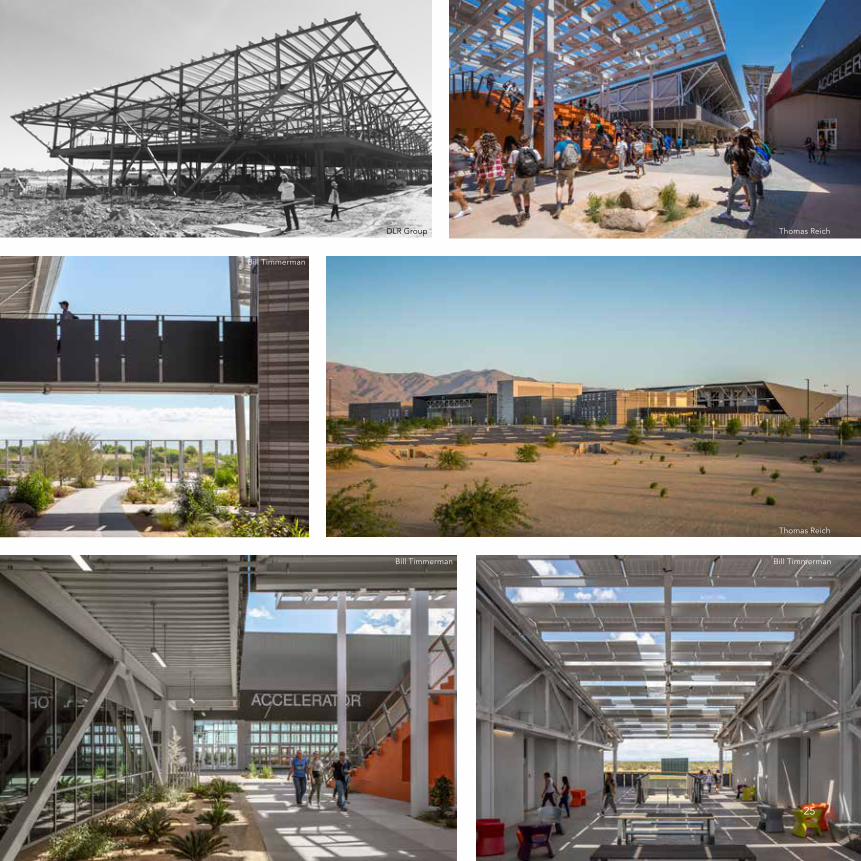
ENERGY EFFICIENCY was the goal for the team behind the new Canyon View High School in Waddell, Ariz.
And its structural system was a driving factor in meeting those goals. The structural system became the centerpiece of the design conversation early on as the key element to providing flexible learning environments that extend to comfortable outdoor spaces. The design team’s exposed structural steel framing concept allows natural lighting to penetrate deep into the learning spaces, creating a unique experience seldom found in a traditional high school.
The new 231,000-sq.-ft high school in a suburb of Phoenix extends beyond the built environment to demonstrate how a building interacts with people, resulting in an unprecedented design that elevates learning. A first-of-its-kind learning “Accelerator” contains unique and flexible space imagined and executed through spatial agility. And towering solar structures shade the central “Agora” that spans the entire length of the campus, maintaining a peak temperature of 85 degrees F. In addition, this 225 KW photovoltaic system contributes 20% of the energy needed for the campus. The shape of human DNA served as a pattern for the building-supported and freestanding cantilevered steel structures that make up the solar components. The structures themselves are yet another learning tool for students.
Early designs had buildings made from the school’s two primary framing systems—steel and masonry—dispersed throughout campus. However, working with contractor Chasse Building Team, architect and structural engineer DLR Group realized labor savings by separating the two building types on either side of the Agora. By rearranging all of the steel buildings to the north side and all of the masonry buildings to the south side, the build team cut nearly two months off the schedule, thus streamlining the work and enabling both steel and masonry subcontractors to work simultaneously. Early and continued
collaboration with the contractor and steel fabricator during the design phase allowed the team to validate cost, detailing, and constructability. Ultimately, this collaboration was instrumental to the success of the project and to achieving the school district’s overall program and design goals.
Exposing the structural elements, as opposed to hiding them behind finishes, helped further reduce the project’s cost. It also demonstrates to students, faculty, and visitors how structural framing elements that are typically hidden can create stability, enclosure, and aesthetic contributions. The structural steel-framed buildings form flexible academic “Forts” that create high volumes for daylighting and extensive shading for the outdoor space. Movable space partitions and mobile, flexible furniture create the spatial agility required for the school district’s curriculum. When it comes to the Accelerator, a long-span steel structure bridges the two masonry buildings to create a cohesive framing and lateral system without introducing a building expansion joint and secondary support/bracing systems. With the space anchored by two masonry buildings on each side, the long-span joist and joist girder system allows for minimal columns, and the masonry buildings create lateral stability for the interior steel framing. In addition, the roof diaphragm design helps resolve the rotational force to the masonry shear walls on each side of the Accelerator and auditorium spaces.
A high-tech school called for high-tech design solutions. The use of animation and virtual reality were key to communicating the design and functionality of the spaces to the client and students. The contractor used 360° photography during construction to help document embedded systems for quality control and future maintenance. Images from an aerial drone—shared with the design team, school district, and community—helped document the construction progress as the new high school took shape.
This high school breaks all the norms of institutional architecture. It actually makes the classroom seamlessly flow into the outside environment.
If I were going back to school now, this is the high school I would want to go to.—Cynthia Duncan
Thomas Reich
Bill Timmerman
Thomas ReichDLR Group
Bill TimmermanBill Timmerman
25

Jim Pearson
26

27
NATIONAL AWARD GREATER THAN $200 MILLION
Wilshire Grand CenterLos Angeles
Steel TeamFabricator, Detailer, and ErectorSchuff Steel Company, San Diego
Additional DetailerBDS VirCon, Brisbane, Australia
ArchitectAC Martin Partners, Inc., Los Angeles
Structural EngineerBrandow & Johnston, Los Angeles
Performance-Based Design ConsultantThornton Tomasetti, Los Angeles
General ContractorTurner Construction Company, Los Angeles
OwnerHanjin International Corporation, Los Angeles
28
WILSHIRE GRAND CENTER is the best in the west. The 73-story steel-framed tower in downtown Los Angeles
is the tallest building west of Chicago and the tallest building in the United States outside of that city and New York. Built for a cost of $1.3 billion, the tower and its podium structure comprise approximately two million sq. ft of space. The upper 43 stories house a 900-room InterContinental Hotel—whose lobby is on the top floor—and the lower 30 stories are reserved for office space. A five-level subterranean parking structure provides space for approximately 1,000 vehicles.
The structural steel-framed tower is geometrically complex, with many of the steel columns sloping over their height to accommodate the curved edges of the structure. Between the 28th and 30th floors, the exterior building columns slope inward 6 ft over three floors to transition the floor plate configuration from office to hotel space. The tower’s columns are embedded the full depth of the 18-ft-thick concrete mat foundation to anchor seismic uplift forces.
The design team implemented a performance-based design methodology to accommodate the owner’s desire for floor-to-ceiling glass in the hotel and office spaces. A code-prescribed lateral design would have required a perimeter lateral system on the structure in addition to the concrete core wall. This would have resulted in deep perimeter beams that would have either increased the floor-to-floor heights or reduced the heights of the perimeter windows—as well as increased construction time in order to add a perimeter moment frame.
The building is designed to be linearly elastic for a service-level earthquake with a 43-year return period, and for collapse prevention for the extremely rare 2,475-year return period earthquake. To achieve this performance, the design team created
three buckling-restrained brace (BRB) regions over the height of the structure. A total of 180 BRBs distribute lateral overturning forces to the exterior concrete-filled steel box columns.
At the top of the structure are ten 2,200-kip BRBs extending from floors 70 to 73, and the single-pin connections for these braces are exposed with a patina finish in the hotel lobby for all to see. Between floors 53 and 59 are 130 800-kip BRBs, with each spanning only one floor and hidden in the hotel room demising walls—a unique configuration that allowed the developer to maximize the hotel room count. Closer to the bottom of the structure, between floors 28 to 31, are 40 2,200-kip BRBs. Bundled in groups of four at ten locations, they span three floors and are capable of resisting 8,800 kips at each location.
The extensive system of BRBs is complemented by perimeter belt trusses around the exterior between levels 28 and 31 and levels 70 and 73. These elements all work together to provide torsional resistance and load path redundancy.
The five-story podium—which also employs structural steel framing, along with concrete shear walls—contains restaurants, retail space, meeting rooms, ballrooms, and a rooftop pool. The podium and tower are seismically separated over the building’s ground-floor lobby, which is covered by an undulating, curved glass roof that pays homage central California’s Merced River. Steel trusses made of round hollow structural section (HSS) members frame the roof and are rigidly attached to the podium at the tower with slip connections designed to move up to 15 in. in any direction.
Wilshire Grand Center is featured in the article “West Coast Boast” from the February 2017 issue of Modern Steel Construction, available at www.modernsteel.com.
The exposed steel at the top of the building, as well as the curvature of the steel down in the lobby area, is really exciting and provides
a great interaction with the public that’s using that space. —Sheryl Van Anne

Len Joseph
Jim Pearson
Jim Pearson
29
Jim Pearson
Brandow and Johnston

Degenkolb Engineers
30
Degenkolb Engineers
31
MERIT AWARD GREATER THAN $200 MILLION
Sutter Health CPMC Van Ness Campus—Viscous Wall DampersSan Francisco
Steel Fabricator and ErectorThe Herrick Corporation, Stockton, Calif.
ArchitectSmithGroup, San Francisco
Structural EngineerDegenkolb, San Francisco
General ContractorHerreroBoldt, San Francisco
OwnerSutter Health, Sacramento, Calif.

32
A NEW SAN FRANCISCO acute care facility is at not only the forefront of healthcare, but also of structural design.
The new $2.1 billion Sutter Health California Pacific Medical Center (CPMC) Van Ness Campus is a 13-story, 989,230-sq.-ft hospital with 274 patient beds and state-of-the-art diagnostic and treatment centers. It is also the first use of viscous wall dampers (VWDs) in the U.S. The building’s 119 VWDs are installed behind the façade on the nine above-grade floors of the 13-story skeleton and will help the facility remain open even after a shock as strong as the 1906 San Francisco Earthquake, which registered a magnitude of 7.9.
Van Ness Campus Hospital (VNC) consolidated the acute care services of two older Sutter Health CPMC campuses to create this new flagship hospital, which opened to patients in March 2019. Given the location in a famously high-seismic city, structural engineer Degenkolb and the rest of the design team studied several seismic-resisting systems via an integrated project delivery (IPD) approach, eventually settling on VWDs. Originally developed and implemented in Japan over the past three decades and seismically superior to more traditional systems, VWDs had never been used in the U.S., nor had the system been reviewed or approved by California’s Office of Statewide Health Planning and Development (OSHPD).
Degenkolb led a team effort to validate the technology, implementing full-scale testing of the dampers at the University of California, San Diego. Based on nonlinear analyses, the VWD system is expected to absorb nearly 90% of the earthquake energy at the design earthquake level. It also reduced the weight of the steel framing by one-third compared to a conventional steel moment resisting frame, thanks to its ability to by control inter-story drift. This helped reduce the
cost of the overall structural system by 25%, which more than offset the cost of the dampers.
The design and construction teams worked together in a “Big Room” across from the construction site. Daily and weekly Big Room meetings kept the project on schedule, even as new team members learned how to function in an integrated project delivery (IPD) environment. The IPD method streamlined the entire process by allowing HerreroBoldt, Sutter Health, and SmithGroup to collaborate from start to finish, with design consultants and contractors working together as early as the validation phase. The team analyzed, scheduled, quantified, and documented the design in real time, reducing waste in the design and construction of the hospital. Degenkolb also worked closely with the steel fabricator, The Herrick Corporation, to drive the VWD production.
In addition, a building information modeling (BIM) approach provided the ultimate coordination, allowing the IPD team to “build” the hospital in the virtual world before going to the site to build the real structure. The entire team was able to observe one another’s work and adjust systems and components before they created real-world clashes. When steel fabrication began, the IPD team needed a way to keep track of the progress and sequence of steel fabrication in the shop. To create an effective method for sharing progress across the structural steel supply chain, the various team members established a standard process for collecting, verifying, and integrating field data to the model to produce a weekly report.
The Sutter Health CPMC Van Ness Campus cleared the way for other structures to implement VWD technology in California and beyond. Future U.S. buildings will now be able to take advantage of this system, which creates the opportunity for improved seismic performance, especially in critically important acute care facilities following powerful earthquakes.
The project advanced the use of viscous wall dampers in the U.S. market to address seismic concerns.
—Hollie Noveletsky

Brett Drury Architectural Photography
Degenkolb Engineers
Degenkolb Engineers
Degenkolb Engineers Brett Drury Architectural Photography
Brett Drury Architectural Photography
33

Matt Breidenthal HOK
34

Matt Breidenthal HOK 35
NATIONAL AWARDSCULPTURE/INSTALLATION/NON-BUILDING STRUCTURE
Hartsfield-Jackson Atlanta International Airport Modernization Atlanta
Steel TeamFabricator and DetailerBeck Steel, Lubbock, Texas
ErectorDerr and Isbell Construction, LLC, Roswell, Ga.
Bender/RollersBendco, Pasadena, TexasChicago Metal Rolled Products, Chicago
ArchitectsHOK, St. LouisChasm Architecture, LLC, AtlantaStanley, Love-Stanley, P.C., Atlanta
Structural EngineerHOK, St. Louis
General ContractorNew South | McCarthy | Synergy, Atlanta
OwnerHartsfield-Jackson Atlanta International Airport, Atlanta

36
HARTSFIELD-JACKSON ATLANTA International Airport (ATL), the busiest in the world, recently looked to transform its 40-year-old terminals by introducing a new architectural icon.
But a question emerged: How could ATL modernize without impacting ongoing operations and risking its title as the world’s most efficient airport? The airport’s planners initially envisioned fabric-covered steel canopies. However, they were structurally problematic as they required new support columns along the terminal curbs and foundations that would have been extremely disruptive to airport facilities located beneath the curbside.
The design team began examining how the canopy might connect to the terminal without the need for new columns at the terminal curb. Using STREAM software (developed by design firm HOK’s engineering group), which performs steel design and optimization, the team developed an alternative canopy design that distributed two-thirds of the structure’s load onto new support piers located near the parking garages, reducing the increased demand and associated retrofit work to the terminal columns by 75%. This process, which typically would have lasted several months, took only three weeks from start to final owner acceptance of the design.
The dual 864-ft-long canopies feature curved hollow structural section (HSS) steel Vierendeel trusses. The compression chords of the trusses are connected by a diagrid. The trusses span 174 ft and are supported along one edge by 10-ft-deep by 21-ft-tall concrete piers, and at the other edge on bearing pads atop the existing terminal columns. Both canopies support two pedestrian bridges that thread through the diagrids, connecting parking garages to the terminal. The sweeping form of the diagrid canopy represents the most efficient structural load path and is key to the canopy design. The diagrid transfers lateral forces to the piers, which are supported by micropiles, and the system provides sufficient elastic deformation to relieve the stresses associated with thermal movement of the structure. At the terminal-side supports, multidirectional slide bearings allow lateral movement of the canopy relative to the existing structure.
The canopies were optimized with fabrication and construction feasibility in mind. While the truss chords appear to have gradually varying curvature, they are actually made of discrete constant-
curvature sections, which are significantly less expensive to fabricate. The design and construction teams worked together to design connections that allowed construction to progress in stages during the overnight road closure time period. The truss splice connections have internal bolts that were rapidly installed and concealed with welded cover plates afterward.
Throughout the project, the airport emphasized that construction of the canopies could not impact operational efficiency. This flipped the usual process on its head. Whereas in most cases logistics are secondary, in this case logistics drove the fabrication. The steel was detailed and sequenced to allow installation during limited roadway shutdowns between 10:00 p.m. and 4:00 a.m. The team used a 4D schedule to explain the sequence of construction associated with a 500-page logistics plan, and 3D printing and virtual reality applications were used to plan and monitor bearing movement during steel erection. This successful collaboration returned the active seven-lane road to service each morning without any delay throughout two years of construction.
The biggest fabrication challenge was controlling steel movement due to welding and temperature changes. Steel fabricator Beck’s fabrication of 38 identical trusses was successful thanks in large part to three key strategies. First, 50 tons of custom fixtures were built and welded to the floor to hold each truss’s position during fabrication. This was crucial because the steel would move during the day as the shop heated up and had to be frequently laser surveyed to monitor the geometry and adjust fabrication as needed. The second strategy involved cutting the HSS members with constantly varying miters that covered a range of 20° to 90° in a single pipe to minimize the amount of required weld material. Beck effectively had to “trick” the CNC machine’s software to make some of these cuts. The alternative would have resulted in two or three times as much welding, which would have exacerbated steel distortion, and providing perfect cuts every time was critical to minimize welds and achieve identical behavior for each truss. And the third strategy? Weld everything flat. Rather than welding around the pipe, Beck kept the welding stationary in a flat position and rotated the steel, performing every weld identically on each truss assembly. This fabrication process involved trial and error but ultimately proved very successful.
The project’s complex 3D modeling had to precisely plan each section component for quick construction, and the pieces had to be timed perfectly.
—Kari Berg

David Camp HOK
Miltivista-drone NSMS
Matt Breidenthal HOK
Matt Breidenthal HOK
Mark Ejnes HOK
37

Ross Barney Architects38

Ross Barney Architects 39
MERIT AWARDSCULPTURE/INSTALLATION/NON-BUILDING STRUCTURE
Belmont Gateway CanopyChicago
Steel TeamFabricator and DetailerKing Fabrication, Houston
Erector and General ContractorThe Walsh Group, Chicago
CastingsCast Connex, New York
ArchitectRoss Barney Architects, Chicago
Structural EngineersEXP, ChicagoSimpson, Gumpertz and Heger, Chicago
OwnerChicago Transit Authority, Chicago
40
FIFTY YEARS AFTER IT WAS BUILT, the Belmont Blue Line Station has been transformed into one of the most recognizable stations in the Chicago Transit Authority’s (CTA) vast rail system.
Upgrading the entrance provided an opportunity to improve the station’s visual presence and create a community focal point within Chicago’s Avondale neighborhood. The design, inspired by a waterfall from the bygone Olson Park, becomes “animated” when it rains as water cascades down the sloping canopy.
The canopy structure is formed by five petal-shaped, architecturally exposed structural steel (AESS) frames that cantilever 68 ft over the station’s plaza and 28 ft in the other direction. AESS emphasizes the overlapping outlines of the petals without adding unnecessary cladding. The primary framing members that form the outline of the petals are built-up rectangular tube sections that support hollow structural section (HSS) purlins that connect to the canopy’s blue polycarbonate panels. The petals frame into a horizontal spine at the low point of the slope with custom castings that are supported on three 38-in. steel-encased concrete pipe columns concealing the drainage downspouts within the concrete.
The canopy’s geometry required the primary structural framing members to be curved in one dimension, sloped in a second dimension, and tapered in the third dimension. The project team was able to simplify fabrication through creative design and by evaluating how the geometry influenced the strength requirements. The primary HSS framing members efficiently resist biaxial and torsional stresses. Rectangular shapes were selected because they are more commonly used in the U.S. and are easier to connect. Plates were cut into trapezoids, curved, and welded together to form the curved tapering sections. Cast steel nodes were selected for the complicated moment connections where the petal loops meet the spine as a means to adequately resist the forces, simplify construction, and meet aesthetic requirements.
The overall structural system includes the cantilevered canopy—which accounts for more than 90% of the project’s total weight (approximately 162 tons)—supported on three columns. A network of primary framing members provides stiffness to control deformations and is anchored to the ground with large concrete-filled steel columns that act as “tree trunks” to support the overlapping steel “branches” of the canopy.
To transfer significant biaxial bending forces and torsion into the columns, accommodate the downspouts concealed within the columns, and provide access to place the concrete in the columns, the design team worked closely with the cast steel designer and supplier Cast Connex to develop customized cast-steel connection nodes. Coordinating this design decision early in the schematic phase allowed the project team to evaluate the connection’s ability to meet the required demands of the structure and provide confidence to the design team and CTA that the project vision would not be compromised within future phases of the job. In addition, minimizing the disruption to the surrounding area was important to CTA and the project team. A deep foundation system with small-diameter drilled piers was chosen to bypass existing below-grade structures and limit the effects on the adjacent street, active bus routes, and subgrade trains.
This design-build project provided many opportunities for the design, casting, and fabrication teams to collaborate. Bringing these parties together early allowed the project team to work together to develop creative, efficient, and successful solutions. The design team used 3D and structural analysis models to coordinate and evaluate this complex structure, as well as to help facilitate information sharing. Architectural models developed in Rhino 3D were incorporated in the structural analysis model, while customized software packages were used to automate portions of the analysis and evaluate numerous iterations and structural variables: the size of the AESS framing, considering the varying cantilever lengths; framing plans (e.g., numbers of columns, petals, and intersecting petal nodes); plate thickness for the primary petal framing; column diameters and thicknesses; and the amount of welding required. The automated parametric structural analyses enabled the design team to analyze stresses and deflections for each combination of options and achieve the aesthetic goals while helping to minimize fabrication and erection costs.
The cantilevered boxed sections were fabricated out of 2-in. 50-ksi steel plate with mostly complete joint penetration (CJP) welds. AESS requirements reduced tolerances by half, minimized joint gaps, and stipulated that all welds had to be continuous with a uniform and smooth appearance within close visual proximity.
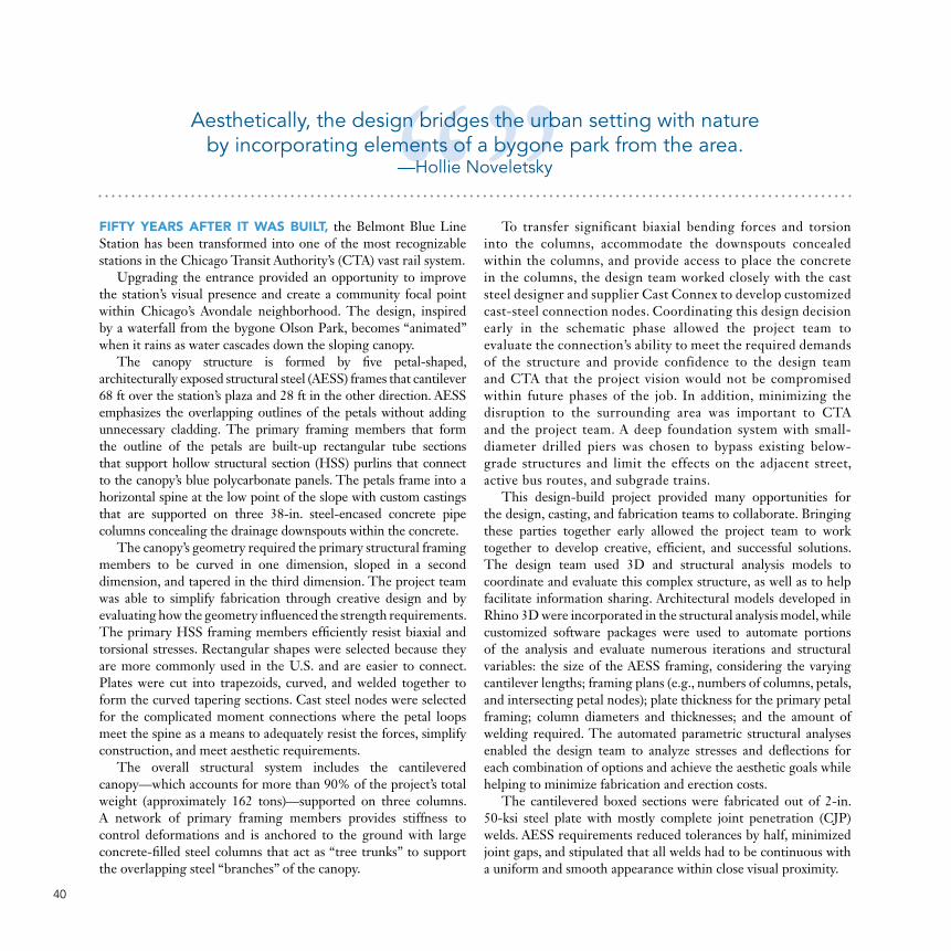
Aesthetically, the design bridges the urban setting with nature by incorporating elements of a bygone park from the area.
—Hollie Noveletsky

Ross Barney Architects
Ross Barney Architects
Ross Barney Architects
Ross Barney Architects
Simpson, Gumpertz and Heger 41
Ricardo Pulido
42

Ricardo Pulido
MERIT AWARDSCULPTURE/INSTALLATION/NON-BUILDING STRUCTURE
Little Charlotte Office Monumental Stair Charlotte, N.C.
43
Steel Fabricator, Erector, and DetailerC.M. Steel, Inc., York, S.C.
Owner, Architect, and Structural EngineerLittle Diversified Architectural Consulting, Charlotte, N.C.
General ContractorDPR Construction, Charlotte, N.C.

44
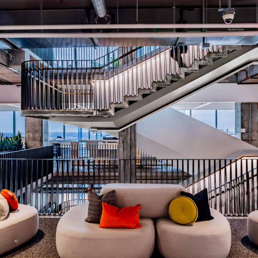
WHEN IT RECENTLY RELOCATED to a new high-rise in downtown Charlotte, N.C., architecture and engineering firm Little didn’t just move into a new space; it created a new experience by designing its own flexible, attractive, and sustainable space, which is pursuing LEED and WELL Silver certifications. The new office occupies the 14th, 15th, and 16th floors of the building. And connecting all three floors is an open, internal staircase that acts as a focal point and an architectural center of gravity.With the stair connecting all three of Little’s floors, the team was able to remove the mildly reinforced concrete slab and a 21-in. mildly reinforced concrete beam at two levels, which totaled 28 tons of concrete—more weight than the stair itself.
Instead of being traditionally anchored and reinforced at the lowest level, which would disturb existing tenants on the 13th floor below, this 15-ton stair hangs from a four-pronged structural mast anchored to the underside of the building’s 17th floor. The four-pronged structural mast distributes the load of the stair to the underside of the 17th floor beams with bolted steel channels and transfers some of the load to the 16th and 15th floors, allowing the existing structure to adequately carry the appropriate load as required by code. Approximately 55% of the dead and live loads are carried by the 17th floor, while the 16th and 15th floors support the remainder of the load transferred from the inside HSS14×4 stringers. The mast connection to the 17th floor is accomplished by four 2¼-in.-diameter pins, and was used to eliminate the transfer of any moment into the existing structure while also complementing the rawness of the design.
The main stair structure was designed to give the impression that the stair floats. Two HSS10×6 outriggers are cantilevered from the steel mast at each level supporting each HSS14×4 stringer, and an HSS14×4 outrigger cantilevers from the mast to support the landing. The main HSS14×4 stringer runs along the inside edge of the stair directly under the inside railing and is supported by the 15th and 16th floors as well as the HSS10×6 outriggers at the intermediate landings, which frame back to the center mast. A secondary HSS6×6 stringer runs along the stair
approximately 2 ft, 4 in. from the outside edge of the stair. The architects requested that the edge of the stair treads be exposed steel and termed this element the “zipper,” which in turn supports the outside railing.
Even with diligent planning from both the engineering and design team, the stair execution did not come without its challenges. One obstacle was the limited size of the building’s freight elevator, which in turn limited the size of elements and assemblies that could be transported to the space. The solution? Construct the stair at the fabricator’s (C.M. Steel) shop and then cut it into 42 pieces to be delivered and reconnected on-site. Once in the space, the stair was pieced back together using full-penetration welds. The construction sequence took advantage of the existing floor by installing the hanger framework on the underside of the 17th floor prior to cutting the new holes in levels 16 and 15.
The team also had to take care not to damage rebar and post-tensioned (PT) cables while adding the connections to the 17th floor and attaching the stringers to the 15th and 16th floors (bolted to the PT girders). X-ray and ground-penetrating radar allowed the team to locate all reinforcement and PT cables prior to drilling.
While the structural integrity of the stair was important, so was its architectural design. A winding ribbon of structural steel creates a finished backbone rendered in white, contrasting with the rawness of the steel that it threads together. All exposed steel was left to patina for several months in the field. It was later rubbed with a protective bee’s wax (selected to meet the WELL requirements for the space).
The apparent hand of the craftsperson was also integral, and the materials used were critical in how the stair would invite users—the more “raw,” the better. Bolted connections, welds, bends, and cuts express the inherent beauty of the materials in terms of how they look, feel, and sound. To keep with this intentional rawness, the visible welds were only lightly ground, and the railing surrounding the stairway mimics the shading of architectural sketches.
Hanging a staircase in the middle of an office space and looking at the design of the space and how it interacts with the users really draws you in. It makes you
want to learn more about the project and really interface with the design. —Sheryl Van Anne

four pronged structural mast
metal ribbon
railing
locally sourced stone treads
HSS10×6 outrigger
HSS6×6 secondary stringer
HSS14×4 main stringer
17×22-ft slab opening
2¼” pin connection
channels – bolted to concrete beams
existing concrete beam
LEVEL 17
LEVEL 16
LEVEL 15 zipper
LEVEL 14
existing concrete slab
mast tip – stops 24” above 14th floor
Ricardo Pulido
Ricardo Pulido
Ricardo PulidoTim Buchman
45
Congratulationsto this year’s winners!
2020IDEAS2
AWARDS

47
WHO IS ELIGIBLE?Architects, engineers, designers, constructors, fabricators, and owners may enter building projects that meet the following criteria:• At least 50% of the structural steel for the project must have been produced and fabricated by
a company eligible for AISC full membership or a unique or distinctive feature of the project must have been fabricated by a company eligible for AISC full membership.
• Projects must have been completed in the U.S. between Jan. 1, 2018 and Oct. 15, 2020. • Entries must include identification of the project team related to the use of structural steel; project
size and cost information; a description of the project, including elements such as architectural accomplishment, structural engineering achievement, innovative project teamwork, and productivity enhancement; and high-resolution photography and drawings released to AISC for use.
HOW TO ENTERSubmit a project for a 2021 IDEAS² Awards at aisc.org/ideas2 by October 15. Please contact [email protected] with any questions.
2021IDEAS2
AWARDS
Call for Entries


Smarter. Stronger. Steel.American Institute of Steel Construction312.670.2400 | www.aisc.org
P110-20