Embed Size (px)
Citation preview

1

2
Used in the products that are a step further than their counterparts
Represents theproducts of energycontinuity andmeasurable energy efficiency
Used in the products that have smartcontrol logic
Represents the products which are easy-to-useand where difficult tasks are made easier
Represents the “green” products that respect the nature and our future

3
Metering & Management
ActWin Smart Metering Software ............................................................................................... 8-10GPRS Communication Units - NCP12 ............................................................................................. 11
Medical Power Solutions
Isolated Power Distribution Panel - IGTP........................................................................................ 14Isolated Power System ................................................................................................................... 15Medical Isolating Transformers - IT ................................................................................................ 16Operating Theater Control Panels - OCP ........................................................................................ 17
Power Quality Solutions
Power Quality Engineering ............................................................................................................. 20Harmonic Filter Reactors - AR ....................................................................................................... 21Shunt Reactors - SR ........................................................................................................................ 22Shunt Reactor Banks - SRS ............................................................................................................. 23Compensation Rack Units - P5 ....................................................................................................... 24Compensation Rack Units - R7 ...................................................................................................... 25Compensation Rack Units - R7s ...................................................................................................... 26Capacitor Banks - M ....................................................................................................................... 27Capacitor Banks with detuned harmonic filters - MS .................................................................... 28Thyristor controlled capacitor banks with detuned filters ............................................................. 29HV Capacitor Banks - MLC ............................................................................................................. 30Static Electronic Switches - Thymod .............................................................................................. 31
MV Products
Metal Enclosed Switchgear - SME ................................................................................................. 34Metal Clad Switchgears - SNC ........................................................................................................ 36Metal Clad Switchgears - SMC ....................................................................................................... 38Rotary Disconnectors - SRS ............................................................................................................ 40Earthing Switches - SES .................................................................................................................. 41Neutral Grounding Resistors - SRG ................................................................................................. 42Load Banks - SRL ............................................................................................................................ 43
MV Substations
Compact Substations made by Steel Sheet - SCK .......................................................................... 46Compact Substations made by Concrete - SMK ............................................................................. 47Compact Solar Substations - RST .................................................................................................... 48Mobile Substations - SMS .............................................................................................................. 49
Power Converters
Modular Type Solar Inverters ...............................................................................................................52String Boxes ..........................................................................................................................................53
Traction Power Distribution
Traction Rectifiers .................................................................................................................56DC Circuit Breaker Cubicles ...................................................................................................57Disconnecting Cubicles .........................................................................................................58Track-side and Depot Disconnecting Cubicles ........................................................................58Negative Voltage Limiting Devices .........................................................................................59
44
Companies & Shareholders
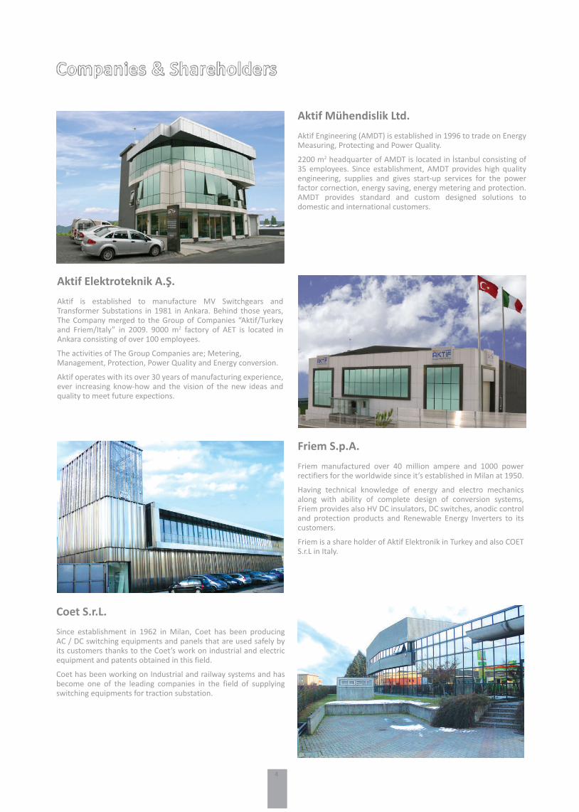
Coet S.r.L.Since establishment in 1962 in Milan, Coet has been producing AC / DC switching equipments and panels that are used safely by its customers thanks to the Coet’s work on industrial and electric equipment and patents obtained in this field.
Coet has been working on Industrial and railway systems and has become one of the leading companies in the field of supplying switching equipments for traction substation.
Friem S.p.A.Friem manufactured over 40 million ampere and 1000 power rectifiers for the worldwide since it’s established in Milan at 1950.
Having technical knowledge of energy and electro mechanics along with ability of complete design of conversion systems, Friem provides also HV DC insulators, DC switches, anodic control and protection products and Renewable Energy Inverters to its customers.
Friem is a share holder of Aktif Elektronik in Turkey and also COET S.r.L in Italy.
Aktif Elektroteknik A.Ş.Aktif is established to manufacture MV Switchgears and Transformer Substations in 1981 in Ankara. Behind those years, The Company merged to the Group of Companies “Aktif/Turkey and Friem/Italy” in 2009. 9000 m2 factory of AET is located in Ankara consisting of over 100 employees.
The activities of The Group Companies are; Metering, Management, Protection, Power Quality and Energy conversion.
Aktif operates with its over 30 years of manufacturing experience, ever increasing know-how and the vision of the new ideas and quality to meet future expections.
Aktif Mühendislik Ltd.Aktif Engineering (AMDT) is established in 1996 to trade on Energy Measuring, Protecting and Power Quality.
2200 m2 headquarter of AMDT is located in İstanbul consisting of 35 employees. Since establishment, AMDT provides high quality engineering, supplies and gives start-up services for the power factor cornection, energy saving, energy metering and protection. AMDT provides standard and custom designed solutions to domestic and international customers.

55
Aktif Values
Service ContinuityThe service continuity means efficiency of power and consequently, the profitability of the business.
Our products are designed and manufactured in order to ensure energy sustainability and provide the best service availability.
Aktif ValuesAKTİF values are the group commitment to our customers, our employees, our shareholders and all of the communities at which we play role directly or indirectly.
Our Values are;
· Customer satisfaction· Loyalty· Profitability· Liability· Totality· Equity· Corporation
Quality and EnvironmentFive symbols represent our one step beyond, high quality product and symbolize environmentally-conscious green products. They provide energy continuity and measurable energy efficiency. Also symbolizes products which hard work simplified, easy to use, smart control logic available.
Mision StatementIn order to contribute our stakeholders’ success and to improve our footprint in terms of technology, price, quality, environment and delivery performances, our mission is to bring the most competitive product and service solutions making energy simple for our customers through with offering possible broadest portfolio.
Vision StatementEnergy is one of the basic requirements for worldwide economic development but the greenhouse gases effect depends to great extent on how the energy is produced. We, as AKTİF Group, do endorse Global compact and sustainable development as one of the pillars of our business approach.
We want to be recognized by our stakeholders as the very best performer in competitive energy market in order to achieve the greatest possible returns by innovating, designing, expositing and placing competitive products and services for sustainable and habitable environment by enhancing the standards of living for our planet.

6
ActWin Smart Metering Software ..................................................................................................................... 8-10GPRS Communication Units - NCP12 ................................................................................................................... 11
Metering & Management

7
AMetering &Management
Building
Solar Systems
Industry
Energy

8
ActWin Smart Metering Software
Actwin Smart is an energy management and AMR software that automatically gathers data from devices like meters (electricity, water, gas etc.), analyzers, relays, remote IOs and prepares reports and invoices.
• Multi language support • Ability to use commonly used and secure Microsoft SQL, Oracle databases… • Distributed structure like “server”, “client”, and “internet” interface. • “Server” is the main engine as working at background and collects data from devices.• “Client”, the application part which management is done with interaction to server. Server and client interfaces are desktop applications. • “Internet interface” provide, users (like factories) to enter the system and monitor consumption, energy quality and create reports of their own devices.
Software Modules:
• Communication and data validation • Reporting • Billing • Loss/Leakage Detection • Single-Line Diagram and Map presentation• Integration with web services • Alarm Management, SMS and e-mail notification • Internet interface • User Management and Inventory • Authentication Actwin Smart has modular structure to provide different new
protocols to be found in the future. Supported protocols are listed below.
Communication principle is compatible with “push” and “pull” structure. Data collection schedule, result saving to the database schedule can be defined and measurement parameters that will be read from each the device can be defined independently.
Communication module starts automatically when server starts as windows service. This prevents users from accidently closing the data collection application.
Communication Protocols: • IEC 62056-21 Mod C and constant baud rate • DLMS/Cosem• Modbus-RTU• Modbus-TCP/IP• M-Bus• Wireless M-Bus
Communication Interfaces :• Serial communication (RS485, RS232)• GPRS• M-Bus• Ethernet• PLC (DLC)• RF
Communication

9
ActWin Smart Metering Software
Reports can be prepared as below with collected data. The modular structure provides capability to add new reports to the software when needed. There is no need to upgrade or modify the software when a new report is requested. All reports can be exported as MS Excel, MS Word, HTML and PDF.
• Reporting as a table of all selected device measurements. Also measurements to be reported can be selected.• Graphic display of desired device measurements. Multiple device measurements can be drawn on the same chart.• Measurement points can be compared with algorithms like consumption, average values etc…• Active and reactive energy ratio reports for electricity meters. • Consumption reporting for electricity meters according to energy tariffs. • Distribution network load reports (Transformer, gas stations) • Measurement point daily, monthly, and yearly consumption reports. • Map display, showing the measurement points with filters (Reactive energy, low consumption, loss/fraud situations, no communicated points etc…).• Transformer loss report • Total consumption of distribution network as monthly and yearly, import/export with comparison between time periods. • Defined gas component reports. • Natural gas minimum/maximum hourly, daily consumption report. • Measurement point inventory report • Measurement point communication performance report • Water meters low/extreme consumption report
Reporting
• Loss/Leakage reports can be prepared manually and automatically. Automatically prepared reports can be sent to defined person as e-mail. • Electricity meter parameters (events, current/voltage/power/ power factor/phase angle etc…) can be monitored continuously and alert operators if an unexpected measurement or ratio is measured.• Unexpected consumption differences are detected between main distribution points and points connected to that distribution point. • The interventions to meter and panel covers can be detected and operators can be alerted.
Loss/Leakage Detection
Measurements should not be used on invoices and reports before data validation. For that reason some data validation methods like below are used.
• Is measurement in or not in specific limits • The ratio of measurement according to previous periods consumptions• The change ratio according to last measurements• Is measurement in or not in standard deviation according to average value of last billing periods• Check between measurement unit and measurement
Data Validation
Integration Synchronization to other systems like ERP, accounting, geographic informative, bank etc… can be provided with Web Services.

10
ActWin Smart Metering Software
Report can be generated from all type records that are saved in database like defined measurement points, customers and groups.
• New user and/or measurement point can be defined without professional skills with copy paste method. • There is no limit in user defined information on measurement point and customer cards. Some predefined information are:
> Customer Number > User Name > Address/Parcel İnformation > User Type > Start in operation date> Authorized Person > Contact information like phone, fax, e-mail etc.> GPS coordinates
• Reports can be taken from these defined information, and then allowed to grouping, listing and filtering can be made.
Customer Management and Inventory
• Electrical distribution network can be showed on single-line diagrams like SCADA systems and the information of instruments like electrical meters, seconder protection relays on this network can be monitored.• Electrical meter’s power-current/voltage values, secondary protection relay’s on/trip situations and quality recorder’s power-current/voltage values can be monitored with digital and analog instrument display.• Gas meters, measurement values, filter impurity situations, door/valve situations belong to type B and C stations can be displayed.• Drag and drop support.• Infinite number of screens can be created.
Single-line Diagram
• Event record on measurement instruments can be saved and reported on database. • System watches reactive energy consumptions and if there is a measurement or over the limits, system informs the users with e-mail and SMS.• E-mail and SMS notification can be saved on database and reported later.
Alarm Management
Internet interface have customers monitor their own consumptions and energy quality parameters. Reaching to interface is done by entering username and password and users can only reach their own measurement points.
For security, there is no direct connection through the system in internet. There is a safe web service level between internet interface and database.
• Users can view historical measurement values of their own measurement points • Users can view common or personal messages from management. • Natural gas consumers can send to AMR system their forecasts and check their forecasts reports. • Users may have alerts like reactive penalty, maximum demand exceeding, minimum and maximum gas consumption.
Web Interface
• The roles can be defined with the pre-defined permissions on system. Users can be defined and roles can assigned to users. • Operators can make authentication based on measurement points. They can define which users can reach to which measurement points.
Authorization

11
GPRS Communication Units - NCP12
NCP12 industrial communication device is used to monitor and control electricity, water, gas meters and other control equipment over GSM/GPRS and Ethernet network.
Modem supports commonly used protocols like IEC 62056-21, DLMS/Cosem, Modbus-RTU, M-Bus (with module) etc. This enables NCP12 to communicate and transfer read values to Head-End systems with almost all meters in the market.
Five different simultaneous connections can be opened to the modem. Each connection may send and receive from different serial interfaces like RS485, RS232 and USB. The connections may even send to the same interface and modem will queue and process them in timely fashion and respond to the connection that sent the data.
• Ability to work and notify head-end system for 15 minutes after energy cut off• Two expansion slots for additional communication and IO ports• Wide range ac/dc auxiliary supply.
Technical Features:• ARM Cortex M3 processor, Telit GSM/GPRS module• 1 MB internal memory• 85 – 265 Vac, 120 – 370 Vdc auxiliary supply• 2 pcs digital output (expandable and can be used as relay output)• 2 pcs digital input (expandable)• 25F Super capacitor to notify energy cut off while de-energized for 15 minutes.• Remote firmware update
X0
0
0
0
R
L
M
1
Z
2
44
E
X X X X2 Digital Input / 2 Digital Output2 Digital Input / 2 Relay OutputReusable BatterySupercapExpansion ModuleWired M-Bus (for mechanical meter)Zigbee Communication ModuleStandard Memory1 GB Memory2 GB Memory4 GB Memory2 and 4 Wired Cascaded RS4852 Wired RS485 and Ethernet
NCP12 Type Selection Table
- - CM
NCP12
NCP12

12
Isolated Power Distribution Panel - IGTP..............................................................................................................14Isolated Power System .........................................................................................................................................15Medical Isolating Transformers - IT ......................................................................................................................16Operating Theater Control Panels - OCP ..............................................................................................................17
Medical Power Solutions
13
BMedical PowerSolutions
Medical Plants
14
Isolated Power Distribution Panel - IGTP
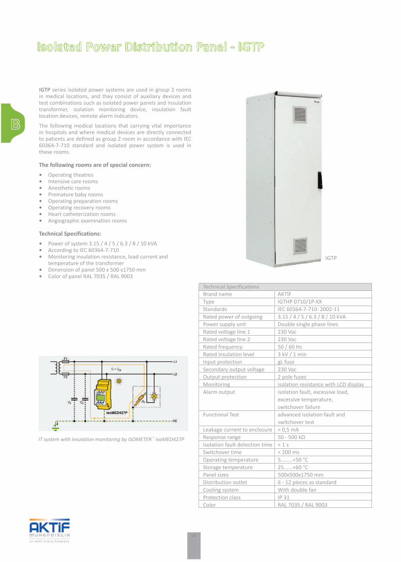
IGTP series isolated power systems are used in group 2 rooms in medical locations, and they consist of auxiliary devices and test combinations such as isolated power panels and insulation transformer, isolation monitoring device, insulation fault location devices, remote alarm indicators.
The following medical locations that carrying vital importance in hospitals and where medical devices are directly connected to patients are defined as group 2 room in accordance with IEC 60364-7-710 standard and isolated power system is used in these rooms.
The following rooms are of special concern:• Operating theatres• Intensive care rooms• Anesthetic rooms• Premature baby rooms• Operating preparation rooms• Operating recovery rooms• Heart catheterization rooms• Angiographic examination rooms
Technical Specifications:• Power of system 3.15 / 4 / 5 / 6.3 / 8 / 10 kVA• According to IEC 60364-7-710• Monitoring insulation resistance, load current and temperature of the transformer• Dimension of panel 500 x 500 x1750 mm• Color of panel RAL 7035 / RAL 9003
IGTP
IT system with insulation monitoring by ISOMETER® isoMED427P
Technical SpecificationsBrand name AKTİFType IGTHP 0710/1P-XXStandards IEC 60364-7-710: 2002-11Rated power of outgoing 3.15 / 4 / 5 / 6.3 / 8 / 10 kVAPower supply unit Double single phase linesRated voltage line 1 230 Vac Rated voltage line 2 230 Vac Rated frequency 50 / 60 HzRated insulation level 3 kV / 1 minInput protection gL fuse Secondary output voltage 230 VacOutput protection 2 pole fuses Monitoring isolation resistance with LCD display Alarm output isolation fault, excessive load, excessive temperature, switchover failureFunctional Test advanced isolation fault and switchover test Leakage current to enclosure < 0,5 mA Response range 50 - 500 kΩIsolation fault detection time < 1 sSwitchover time < 200 msOperating temperature 5........+50 °CStorage temperature 25......+60 °CPanel sizes 500x500x1750 mmDistribution outlet 6 - 12 pieces as standardCooling system With double fan Protection class IP 31Color RAL 7035 / RAL 9003

15
Isolated Power System
Double line isolated power panels with insulation fault location unit are the most comprehensive isolated power panels formed from equipments providing determination of line based speed of any isolation failure in group 2 rooms. The panel includes insulation fault evaluator, insulation fault test device and toroidal current transformers and determine from where the failure is sourced in a short time and provide realizing the intervention with minimum time loss via rapid communication and examination capacities of isolation transformers, isolation monitoring device, load current transformer and switchover module.
The process is completed by determining the failure as a result of evaluation of current signal formed by test current generator and size current transformers provided that it forms a response signal after determining a failure by isolation monitoring device and by switchover it to remote monitoring devices.
The EDS151 system works in combination with a central insulation monitoring device with integrated pulse generator,e. g. an ISOMETER® isoMED427P. After an insulation fault the isoMED427P starts automatically the fault location by generating a test signal. Its amplitude and duration are limited. The signal flows via the location of the insulation fault and through all measuring current transformers within the insulation fault path. The EDS151 system scans all measuring current transformers.
The EDS151 with its LEDs or the central control and indicating device (e.g. MK2430) provide fault location information.
Advantages:• Insulation fault location during operation• Fast localisation of faulty circuits/equipment• Reduced maintenance costs• Central indication via LC text display at remote alarm indicator and operator panels.
System functions:• Indication of faulty branch circuits.• Easily retrofitting with existing installations due to the modular design.• Measuring current transformers in different sizes and designs.• Up to 528 sub circuits can be monitored.• Communication via two-wire connection.• Universally applicable for all IT systems.
Isolated Power System
EDS151 insulation fault location system applied in an intensive care unit
Function principle of the EDS151 system

16
Medical Isolating Transformers - IT
IT series medical isolating transformers are designed compatible with IEC 60364-7-710 standards for power supply of single phase IT systems and produced in accordance with EN 61558-2-15 standards. Constant angles are isolated from transformer core thanks to a static display placed among primary and secondary coils.
Asset medical isolating transformers having galvanic isolated coils provide possibility of monitoring of temperature thanks to PTC thermistors placed into coils. Asset medical isolating transformers designed at 6 different power value between 3,15...10 kVA have high excessive load capacities.
Brand ASSETType IT 0710Power range 3.15 / 4 / 5 / 6.3 / 8 / 10 kVAFrequency 50 / 60 HzPrimary Voltage 230 VacSecondary Voltage 230 VacInrush current (Ie) < 12.InLeakage current < 0,5 mANo-load input current (Io) < 3%No-load output voltage (Uo) < 236 VShort-circuit voltage (Uk) < 3%Operating mode continuous operationConnections separate terminal block Max ambient temp. 40 ° CIsolation class 40/BCooling Air coolingPTC resistor 1 resistor per transformer windingProtection class IP 00Standards IEC 603647-710, IEC 61558-2-15
General Features
IT 0710-3,15IT 0710-4IT 0710-5IT 0710-6,3IT 0710-8IT 0710-10
265280280280280320
195195205220235235
325370370370370420
200240240240240270
155155165180195195
8,5x178,5x178,5x178,5x178,5x178,5x17
220220230245260280
5157616574
100
3,15 kVA 4 kVA 5 kVA 6,3 kVA 8 kVA 10 kVA
Size and WeightsType A (mm) B (mm) C (mm) D (mm) E (mm) F (mm) G (mm) H (kg) Power
IT 0710Standard Version
Dimension diagram IT 0710

17
Technical Specifications:• 4 line general illumination control• Control of operation lamp• Negatoscope control• 4 channel music broadcast channel selection• Digital clock and chronometer• 10 channel medical gas alarm panel• Temperature, humidity, room difference pressure, hepa filter pollution indicator• Temperature monitoring and setting, audible and luminous warning when set value is exceeded.• Command for Operating room exists/not exist, flow control• Damper open-close manual control• Electricity heater control
IP65 stainless steel enclosure• 21.5 inch capacitive touch screen• Internet Access via TCP/IP• Touch controlled IP Phone• Customizable user profiles
Operating Theater Control Panels - OCP
OCP series operator control panel is a modern and reliable device designed in order to provide optimal operation conditions that are necessary in operational theatres and to form the most comfortable environment that is possible for surgery team. Touch screen LCD display having easy cleanable IP67 protection standard, room difference pressure and filter pollution level measures are the part of “smart care” checking feature that OCP-10 panel. All electrical control can be done on touch display manually; music broadcast and air conditioner mechanism can be controlled. Communication having high quality sound ensured by digital sound processor with freehand telephone system on the same touch screen LCD display is possible.
Another feature of OCP-10 is that it can do all data exchange necessary for automation and that it can undertake all automation duty in environment that are not central automation by itself.
OCP 10
OCP 10

18
Power Quality Engineering .................................................................................................................................. 20Harmonic Filter Reactors - AR ............................................................................................................................ 21Shunt Reactors - SR ............................................................................................................................................. 22Shunt Reactor Banks - SRS .................................................................................................................................. 23Compensation Rack Units - P5 ............................................................................................................................ 24Compensation Rack Units - R7 ........................................................................................................................... 25Compensation Rack Units - R7s ........................................................................................................................... 26Capacitor Banks - M ............................................................................................................................................ 27Capacitor Banks with detuned harmonic filters - MS ......................................................................................... 28Thyristor controlled capacitor banks with detuned filters .................................................................................. 29HV Capacitor Banks - MLC .................................................................................................................................. 30Static Electronic Switches - Thymod ................................................................................................................... 31
Power Quality Solutions

19
CPower QualitySolutions
Building
Solar Systems
Industry
Energy
20
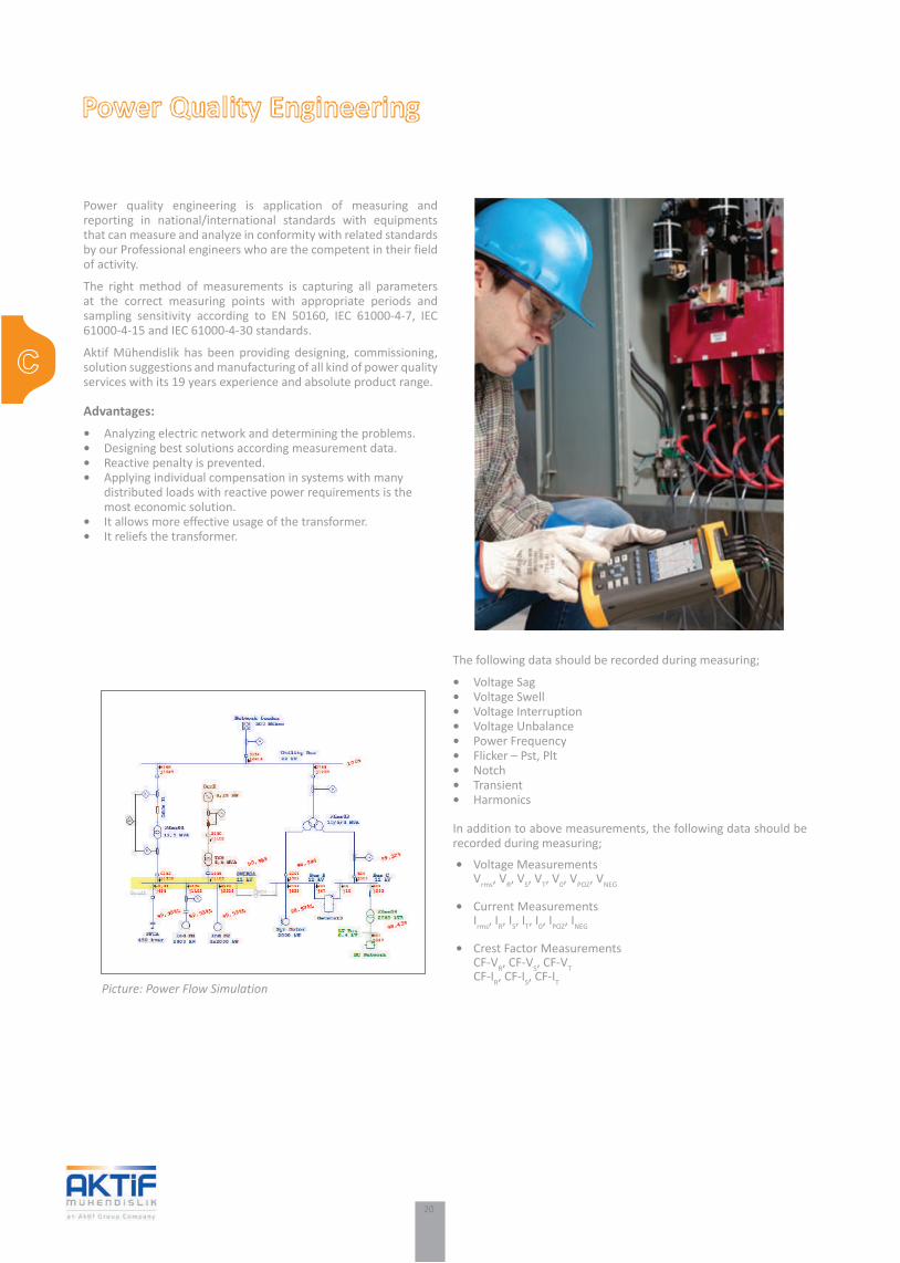
The following data should be recorded during measuring;
• Voltage Sag• Voltage Swell• Voltage Interruption• Voltage Unbalance• Power Frequency• Flicker – Pst, Plt• Notch• Transient• Harmonics
In addition to above measurements, the following data should be recorded during measuring;
• Voltage Measurements Vrms, VR, VS, VT, V0, VPOZ, VNEG
• Current Measurements Irms, IR, IS, IT, I0, IPOZ, INEG
• Crest Factor Measurements CF-VR, CF-VS, CF-VT CF-IR, CF-IS, CF-IT
Power Quality Engineering
Power quality engineering is application of measuring and reporting in national/international standards with equipments that can measure and analyze in conformity with related standards by our Professional engineers who are the competent in their field of activity.
The right method of measurements is capturing all parameters at the correct measuring points with appropriate periods and sampling sensitivity according to EN 50160, IEC 61000-4-7, IEC 61000-4-15 and IEC 61000-4-30 standards.
Aktif Mühendislik has been providing designing, commissioning, solution suggestions and manufacturing of all kind of power quality services with its 19 years experience and absolute product range.
Advantages:• Analyzing electric network and determining the problems.• Designing best solutions according measurement data.• Reactive penalty is prevented.• Applying individual compensation in systems with many distributed loads with reactive power requirements is the most economic solution.• It allows more effective usage of the transformer.• It reliefs the transformer.
Picture: Power Flow Simulation

21
Harmonic Filter Reactors - AR
AR series low voltage harmonic filter reactors are used in the high level of harmonic distortion in facilities for compensating of reactive power and protecting of capacitors. Protecting of capacitor which is main staff in compensation systems and annihilating other negative effects. AR series harmonic filter reactors are manufactured as single phase and three phase. AR series reactors have 3 poles and 6 poles options. Furthermore, reactors have aluminum and copper coil options.
Product Advantages:• Manufacturing according to customer’s request• Aluminum and copper coil options• Easy mounting to different type of panels• High quality and long life period
Technical Specifications:• Rated Voltages : 230 … 1000 V AC• Rated Frequency : 50 / 60 Hz• Resonance Frequency : 134 / 189 / 210 / 225 Hz• Degree of protection : IP 00• Power Range : 0,83 … 150 kVAr• Over Current : 1,35 x In• Linearity Current : 2,1 x In• Inductance Tolerance : Max %3• Rated Temperature : ta 40 oC• Standards : EN 61558-1 , EN 60076-6, VDE 0550
Reactors are also available with your requirements and specs. Please contact with us.
AR3 4450-F70
Power(kVAr)
6,2512,52550
100
400400400400400
77777
33333
AR3 4406-F70-DAR3 4412-F70-DAR3 4425-F70-DAR3 4450-F70-D
AR3 44100-F70-D
3x6,903x3,453x1,733x0,863x0,43
10,0220,0440,0880,17
160,33
16,8333,6767,34
134,68269,35
A185240240300360
C120155175180200
B170210210230280
D95
130130170200
H857494
110120
d7x13,58,5x178,5x178,5x178,5x17
10,212,419,329,951,7
Nominal Voltage
(V)
Accord frequency
(%p)Phase
NumberAktif Model
TypeL (mH) Irms (A) Ilin (A) Width
(mm)Depth (mm)
Height (mm)
Monunting Width (mm)
Monunting Depth (mm)
Mounting Hole (mm)
Weight (kg)

22
Shunt Reactors - SR
SR series shunt reactors have been used in order to compensate capacitive reactive power generated by long and unloaded transmission / distribution lines, thus allowing the flow of more active power through the system and avoiding penalties resulting from increasing of capacitive reactive power/active power ratio. These shunt reactors are the most effective method of compensating capacitive reactive power.
Product Advantages:• Manufacturing according to customer’s request• Aluminum and copper coil options• Easy mounting to different type of panels• High quality and long life period
Technical Specifications:
• Rated Voltages : 230 … 1000 V AC• Rated Frequency : 50 / 60 Hz• Degree of protection : IP 00• Power Range : 0,1 … 50 kVAr• Over Current : 1,35 x In• Linearity Current : 2,35 x In• Inductance Tolerance : Max %3• Rated Temperature : ta 40 oC• Standards : EN 61558-1 , EN 60076-6, VDE 0550
Reactors are also available with your requirements and specs. Please contact with us.
SR - 5040
Power(kVAr)
125
1025
400400400400400
33333
SR-140SR-240SR-540
SR-1040SR-2540
3x509,273x254,633x101,853x50,923x20,37
1,733,468,66
17,3243,30
2,895,77
14,4328,8772,17
A240240300360480
C175175220250215
B220220280260360
D130130170200250
H94
114150170175
d8,5x178,5x178,5x178,5x1711x26
18,125,350,978,0
140,2
Nominal Voltage
(V)
Phase Number
Aktif Model Type L (mH) Irms (A) Ilin (A) Width
(mm)Depth (mm)
Height (mm)
Monunting Width (mm)
Monunting Depth (mm)
Mounting Hole (mm)
Weight (kg)

23
SRS series shunt reactor banks have been designed by using SR series shunt reactors, high technology digital reactive power control relay, protection and control equipment. Application areas of the shunt reactor banks are industrial zones which have long transmission / distribution lines or cables, capacitive load characteristic plants, subway and light rail systems etc.
Product Advantages:• Designed for different voltage and power levels• It helps us in installation and maintenance period thanks to its moduler design• Remote monitoring and controlling with Scada system• Power can be increased by adding panels thanks to it is moduler design
Technical Specifications:• Rated Voltages : 400/690 V• Rated Frequency : 50/60 Hz• Max Power for 1 panel : 100 kVAr• Ambient temperature : -40°C / 55°C• Mechanical resistance for high short circuit powers
Shunt Reactor Banks - SRS
SRS- 10040
Dimensions:

24
Compensation Rack Units - P5
P5 series compensation racks provide to customers different power level options thanks to its modular design. That modular design provides rapid and effective solution during installation, maintenance and system development period.
Production and test periods of P5 series compensation racks comply with international IEC standards. Racks are ready to use and there is no need to add any extra component. Electrical safety of plant is guaranteed thanks to its resist to voltage and current rise. It thanks to effective and fast solutions.
P5 series compensation racks are suitable to install all kind of panels, save labor and time, have possibility to increase power by additional racks thanks to its modular design.
Product Advantages:• It helps us in installation and maintenance period thanks to its modular design.• Withstand 1,18 x Vn over voltage and 1,50 x In over current thanks to Asset VCB series capacitors.• No additional material is required.
Technical Specifications:• Rated Voltage : 400/415 V*• Nominal Frequency : 50/60 Hz• Environment Temperature : -10… +45 °C• Switching : by Contactor
* Please ask for other voltages
P5-121241
Standard types (400 V, 50/60 Hz)
Dimensions for P5 Rack Unit:
Nominal Power (kvar)6,252x6,2512,52x12,5252x25502x50
P5-06141P5-06241P5-12141P5-12241P5-25141P5-25241P5-50141P5-50241
12121212
5106119161624
Reference Number of Steps Weight (kg)

25
Compensation Rack Units - R7
R7 series compensation racks provide to customers different power level option thanks to its modular design. That modular design provides rapid and effective solutions in installation, maintenance and system development period.
Because of capacitors should be protected against to harmonics, harmonic filter reactors are connected to the capacitors in series and protect them against the dangerous harmonic current flows. Asset VCB series capacitors are able to work with %18 over voltage and %50 over current continously. Electrical safety of plant is guaranted thanks to its resist to voltage and current rise.
Product Advantages:• It helps us in installation and maintenance period thanks to its modular design.• Withstand 1,18 x Vn over voltage and 1,50 x In over current thanks to Asset VCB series capacitors.• No additional material is required.• Compensation rack has harmonic filter reactor which protects capacitors against to harmonics.
Technical Specifications:• Rated Voltage : 400 / 415 V*• Nominal Frequency : 50/60 Hz• Resonance Frequency : 189 Hz, 210 Hz, 215 Hz• Switching : by Contactor
* Please ask for other voltages
R7-250044
Standard types (400 V, 50/60 Hz)
Nominal Power (kvar)6,2512,52x12,5252x25502x50100
R7-06144R7-12144R7-12244R7-25144R7-25244R7-50144R7-50244R7-10044
11212121
2030353545506080
Reference Number of Steps Weight (kg)
Dimensions for R7 Rack Unit:

26
Compensation Rack Units - R7s
R7s series compensation racks provide to customers different power options with its modular design. Thanks to modular design that provides rapid and effective solutions in installation, maintenance and system development period. Thyristor switching provides very fast switching and response instantly.
Some of facilities have fast changing loads. It means current level increase / decrease rapidly. When compensating these type of plants, using contactor is not a good way switching because design of a mechanical contactor is not suitable for fast switching and fault in a short time. Because of that using thyristor is the best way as a switching equipment. Electrical safety of plant is guaranteet thanks to its resist to voltage and current rise.
R7s-500044
Product Advantages:• It helps us in installation and maintenance period thanks to its modular design.• It has strength 1,18 x Vn over voltage and 1,50 x In over current thanks to VCB series capacitors.• Protection against to harmonics.• Fast switching.
Technical Specifications:• Rated Voltage : 400 / 415 V*• Nominal Frequency : 50/60 Hz• Resonance Frequency : 189 Hz, 210 Hz, 215 Hz• Switching : Thyristor
* Please ask for other voltages
Dimensions for R7s Rack Unit:
Standard types (400 V, 50/60 Hz)
Nominal Power (kvar)6,2512,52x12,5252x25502x50100
R7s-06144R7s-12144R7s-12244R7s-25144R7s-25244R7s-50144R7s-50244R7s-10044
11212121
2030353545506080
Reference Number of Steps Weight (kg)

27
Capacitor Banks - M
M 30041
M series capacitor banks consist of P5 series compensation racks and smart reactive power control relays.
M series capacitor banks provide to customer different power level options thanks to its racks which have modular design. That modular design provides rapid and effective solutions in installation, maintenance and system development period.
M series capacitor banks switch on / off the steps softly and instantly thanks to high technology digital reactive power control relays. Relay determines to switch on / off the capacitors according to the feedback calculations coming from CT and VT.
Product Advantages:• Easy montage / maintenance thanks to its modular design• Withstand 1,18 x Vn over voltage and 1,50 x In over current thanks to VCB series capacitors.• 5 compensation racks can be put into panel easily thanks to its efficient cooling system. Its power level can be raised up to 500 kVAr.• Protection against touching.
Technical Specifications:• Rated Voltage : 400 / 415 V*• Nominal Frequency : 50/60 Hz• Max. Power for 1 panel : 500 kVAr• Up to 5 racks in one panel• Standarts : EN 61439-1/2, EN 60831-1/2, EN 60076-6, EN 60529, EN 60255-1, EN 60947-4-1
* Please ask for other voltages Panel Dimensions:

28
Capacitor Banks with detuned harmonic filters - MS
MS series capacitor banks consist of R7 series compensation racks and high technology digital reactive power control relays.
MS series capacitor banks provide to customer different power level options thanks to its racks which have modular design. That modular design provides rapid and effective solutions in installation, maintenance and system development period.
MS series capacitor banks switch on / off the steps softly and instantly thanks to high technology digital reactive power control relays. Inrush current limiting characteristics of MS series capacitor banks help to network to not increase the inrush when capacitor units switched on.
Product Advantages:• Easy installation / maintenance thanks to its modular design.• Withstand 1,18 x Vn over voltage and 1,50 x In over current thanks to VCB series capacitors.• Compensation racks have harmonic filter reactor which protects capacitors against to harmonics.
Technical Specifications:• Rated Voltage : 400 / 415 V*• Rated Frequency : 50/60 Hz• Resonance Frequency : 189 Hz, 210 Hz, 215 Hz (and optional other frequencies)• Over Voltage : 520 V (24 hours / day)• Standarts : EN 61439-1/2, EN 60831-1/2, EN 60076-6, EN 60529, EN 60255-1, EN 60947-4-1
* Please ask for other voltages
MS 30044
Panel Dimensions:

29
Thyristor controlled capacitor banks with detuned filters
Some of facilities have fast changing loads. It means current level increase / decrease rapidly. When compansating these type of plants, using contactor is not a good way switching because design of a mechanical contactor is not suitable for fast switching and fault in a short time. The best way is using thyristor as a switching equipment.
MST series capacitor banks are used in facilities which have PLC equipments, industrial type computers etc. Which are breakable devices easily. Production and test periods of MS panels appropriate to international IEC standards. Racks do not need to additional materials. Racks are sent to end users when its all connections are ready to energize.
Product Advantages:• Easy installation / maintenance thanks to its modular design.• Withstand 1,18 x Vn over voltage and 1,50 x In over current thanks to Asset VCB series capacitors.• MST series capacitor banks uses thyristor to switch and so it provides static switching continuosly.
Technical Specifications:• Rated Voltage : 400 / 415 V*• Rated Frequency : 50/60 Hz• Over Voltage : 520 V (24 hours / day)• Over Current : 1.5 In• Standarts : EN 61439-1/2, EN 60831-1/2, EN 60076-6, EN 60529, EN 60255-1, EN 60947-4-1
* Please ask for other voltages
MST 50044
Panel Dimensions:

30
MV Capacitor Banks - MLC
Open type MV capacitor banks are used for power factor correction, voltage support, harmonic suppression and to maximize network capacity in industrial applications and distribution systems. Medium voltage capacitor banks are built up from medium voltage, all-film dielectric capacitor units with separate internal fuses for each element. The impregnation liquid is both non-PCB and non-chlorine. Galvanized steel enclosures are available for indoor and outdoor installations. Design and testing complies with the requirements of the latest edition of relevant standards and the specific technical requirements set by the customers.
Technical Features:• Modular, compact and robust design optimized for easy future expansion of the system, facilitating transport, storage and installation.• Galvanized steel or aluminum open type construction which is available for indoor and outdoor installations.• Design and testing complies with the requirements of the latest edition of relevant standards and the specific technical requirements set by the customers.• Use of simplified design and proven components ensures high reliability and low maintenance costs.• Optimized to give a low environmental load by using recycled materials.• The banks are supplied as fully assembled units, factory tested and ready for connection. MLC
500K/7,2

31
Thymod
Static Electronic Switches - Thymod
2 Phase Control Connection Schema
3 Phase Control Connection Schema
Thymod series static electronic contactors are the electronic switching units that used for switching units that used for the capacitor banks without any discharge delay in the plants where switching the capacitor banks according to load variation cannot be possible and changes load variation fast.
ThyMod series static electronic contactors have been developed according to the related IEC standards to balance the reactive power and solve the energy quality problems in complex industrial plants where used devices that are sensitive to voltage changes such as PLCs, industrial computers, industrial robots, welding machines.
Product Advantages:• Ultra-rapid power factor compensation• Zero crossing technology• Transient free switching• Silent capacitor switching• No need to wait for discharge time before re-switching• Unlimited number of switching operations• Modular and compact standardized design• Easy to install and replace• Long life• Power steps up to 100 kVAr• Direct connection up to 480 V
Technical Specifications:• Rated Voltages : 400 / 415 V*• Max. Operation Voltage : 480 V AC• Rated Frequency : 50 / 60 Hz• Rated Current : Up to 160 A• Response time : <40 ms• Degree of protection : IP 20• Operation Temperature : -10 oC / + 55 oC• Type Of Semiconductor : Thyristor – Thyristor Module• Mass : 6100 g• Dimensions (WxDxL) : 125 x 225 x 240 mm• Mounting : Vertical Mounting to mounting base• Standards : EN 60429-1 , IEC 60439-1, IEC 60439-2
* Please ask for other voltages
Product PortfolioModel Connection
TypeMaximum step power at 400V nominal busbar voltage
Thymod-25400-3P2Thymod-50400-3P2Thymod-100400-3P2Thymod-25400-3P3Thymod-50400-3P3Thymod-100400-3P6
2 phase 2 phase2 phase3 phase3 phase3 phase
25 kVAr50 kVAr100 kVAr25 kVAr50 kVAr100 kVAr

32
Metal Enclosed Switchgear - SME ....................................................................................................................... 34Metal Clad Switchgears - SNC .............................................................................................................................. 36Metal Clad Switchgears - SMC ............................................................................................................................. 38Rotary Disconnectors - SRS .................................................................................................................................. 40Earthing Switches - SES ........................................................................................................................................ 41Neutral Grounding Resistors - SRG ....................................................................................................................... 42Load Banks - SRL .................................................................................................................................................. 43
MV Products

33
DMV Products
Building
Industry
Energy

34
Metal Enclosed Switchgear - SME
Applications:Metal Enclosed Switchgears are especially used in the transformer centers, distribution systems, renewable energy production and industrial plants where the rated current up to 1250 A and short circuit current up to 25 kA.
• Energy Distribution Centers• Hydroelectric and Wind Energy Applications• Diesel and Natural Gas Power Plants• Transformer Substations• Cement Factories• Auto Industry• Petroleum and Chemical Industry• Iron and Steel Industry• Rolling Mills• Pipe lines• Shipyards• Emergency Situation and Stand-by Power Facilities• Mining• Railway Substations
SME series metal enclosed switchgears are the switching and control cubicle which are manufactured between 1 kV and 40,5 kV voltage level.
SME series metal enclosed switchgears are manufactured according to IEC 62271-200 standards.
Product Advantages:• LSC-2A loss of service continuity• PI partition class• AFL internal arc classification• 3 separated and earthed accessible compartments• Internal arc test up to 25 kA/1s• Electrical and mechanical safety interlocks systems do not allow to operational faults• Optional withdrawable circuit breaker allows fast and easy servicing• Air insulated rotary switch option• Reliable design and low maintenance cost• 2 mm sheet steel
Technical Features:• Rated Voltage : 3,6... 40,5 kV• Power Frequency Withstand Voltage : 10... 85 kV• Lightning Impulse Withstand Voltage : 40... 185 kV• Rated Frequency : 50 / 60 Hz• Rated Current : 630... 1250 A• Short Time Withstand Current : 16… 25 kA (1 s)• Internal Arc Withstand Current : 16… 25 kA (1 s)• Protection Class : IP3x / 2x (Doors are closed / Between Compartment)
SME
Model
SME/0
/1
Description
Air Insulated Metal Enclosed Switchgear, Front Access
Air Insulated Metal Enclosed Switchgear withdrawable Circuit Breaker, Front Access
KDD(Max)
25 kA/1s
25 A/1s
Type
630 A
630 A
375
375
900
900
2000
2000
1400
1400 2250
22502000
20001000
1000
12 kV 24 kV 36 kV
1250 A
1250 A
750
750
LBSSF6 GBMeasureLBSSF6 GBMeasure
50090010005009001000
7501000115075010001150
Current(Max)
Dimensions (mm) (W x D x H)Dimensions

35
Metal Enclosed Switchgear - SME
Technical SpecificationsSME-1 3,6
3,63,61040
SME-1 7,27,27,22060
SME-1 1212122875
SME-1 17,517,517,53895
SME-1 24242450
125
SME-1 36363670
170
SME-1 40,540,540,585
185
DescriptionRated VoltageRated Insulation VoltageRated Power frequency withstand voltageRated Lightining impulse withstand voltageSwitchgears insulationCircuit breaker insulationLoss of service continuityPartition classInternal Arc classificationRated frequencyRated short time withstand currentShort time withstand durationInternal Arc withstand currentInternal Arc withstand durationRated main busbar currentRated feeder currentProtection Class (When doors are closed)Protection Class (Between compartments)ColorStandards complied
AirSF6 GasLSC-2A
PIAFL
50/6016/25
116/25
1630 - 1250200 - 1250
IP3XIP2X
RAL 9003IEC 62271 - 200
kVkVkVkV
HzkA5kA5AA
Mechanical Interlock SME/0 SME/1Between disconnector / withdrawer / track and earthing disconnector aBetween disconnector / withdrawer / track and circuit breaker a
Between disconnector / withdrawer / track and CB compartment door a
Between CB compartment door and earthing disconnector a
Functional PropertiesInsulation of circuit breaker SF6Insulation of main disconnector SF6 / AirWithdrawable circuit breaker - aWithdrawable voltage transformer - Control cable entries from top, bottom and sides aReady to Scada connection OpsRemote CB on/off OpsHinged CB compartment door a
Manual spring charging when circuit breaker at test position -Manual spring charging when circuit breaker at service position a
Manual on/off when circuit breaker at service position a
Manual on/off when circuit Breaker at test position -Mimic single line diagram and positioning indication of switching equipment a
Disability of putting in to service position without fixing the withdrawer/truck to panel -Disability of putting in to service position without closing circuit breaker door a
Disability of opening earthing switch without closing circuit breaker door a Disability of circuit breaker doors closing without CB socket plugging in -Disability of circuit breaker operation when circuit breaker is not on test or service position OpsDisability of disconnector’s closing while disconnector is open a
Fast and easy changing of same valued circuit breakers between each other a
Disability of a circuit breaker connecting inside to different valued cubicle. a
Exhaust OptionsExhaust from top, inside substation -Exhaust from rear, inside substation a
Exhaust to outside of substation by using front, rear or lateral arc channel -

36
Applications:• Energy Transmission and Distribution Centers• Hydroelectric Power Plants• Diesel and Natural Gas Power Plants• Transformer Substations• Cement Factories• Automotive Industry• Chemical Industry• Iron and Steel Industry• Rolling Mills• Pipelines• Electro Chemical Facilities• Shipyards• Emergency Situation and Stand-by Power Plants• Mining Industry• Railway Substations• Oil and Gas Industry
SNC Series Metal Clad Switchgears are switching and control cabinets manufactured between 1kV to 24 kV in conformity with IEC 62271-200 standards.SNC series metal clad switchgears are manufactured in compliance with passed type tests successfully in the accredited international laboratories in Europe according to IEC 62271-200 and standards.
Product Advantages:• LSC 2B Loss of Service continuity• PM Partition Class• AFLR internal arc classification• 4 or 5 separated and earthed accessible compartments• Internal arc test up to 40 kA • Electrical and mechanical safety interlocks• Quick and easy service with withdrawable Vacuum / SF6 CB• Quick and easy service with withdrawable voltage transformer (Optional)• 3 mm sheet steel
Technical Features:• Rated Voltage : 3,6... 24 kV• Power Frequency Withstand Voltage : 10... 50 kV• Lighting Impulse Withstand Voltage : 40... 125 kV• Rated Frequency : 50 / 60 Hz• Rated Current : 630... 2500 A• Short Circuit Withstand Current : 16... 40 kA (3 s)• Internal Arc Current : 16... 40 kA (1 s)• Protection Class : IP4x / 2x
Metal Clad Switchgears - SNC
SNC
Model
SNC
1
2
Insulation Description
Air 2B
Air 2B
LSC
WithdrawableCB Vacuum insulated Front Access
Both withdrawableVT & CB Vacuum insulatedRear Access
25 kA / 3s
25 kA / 3s
31,5 kA / 3s
31,5 kA / 3s
40 kA / 3s
40 kA / 3s
SCC(Max)
Type
VCB
VCB
2450
2450
---
---
---
---
---
---
---
---
---
---
---
---
---
---
---
---
---
---
2000
2000
1400
1750
2565
2565
1750
1750
12 kV 24 kV 36 kV1250 A2500 A1250 A1250 A2500 A3150 A (*)1250 A2500 A1250 A1250 A2500 A3150 A (*)
650100065080010001000650100065080010001000
8001000
8001000
Current(Max)
Dimensions (mm) (W x D x H)Dimensions
(*) Please ask for detailed information.

37
Metal Clad Switchgears - SNC
SNC Series Metal Clad SwitchgearTechnical Characteristics
Description SNC 3,6 SNC 7,2 SNC 12 SNC 17,5 SNC 24 Rated voltage kV 3,6 7,2 12 17,5 24 Rated insulation voltage kV 3,6 7,2 12 17,5 24 Rated power frequency withstand voltage kV 10 20 28 38 50 Rated lightning impulse withstand voltage kV 40 60 75 95 125 Switchgear insulation AirCircuit breaker insulation Vacuum / SF6 GasLoss of service continuity 2BPartition class PMInternal arc classification AFLRRated frequency Hz 50/60Rated short time withstand current kA 16/25/31,5/40Short time withstand duration s 3Internal arc withstand current kA 16/25/31,5/40Internal arc withstand duration s 3Rated main busbar current A 630 - 2500Rated Feeder Current A 200 - 2500Protection Class ( When doors are closed) IP4XProtection Class ( between compartments) IP2XColour RAL 9003Standards Complied IEC 62271—200
Mechanical Interlock SNC/1 SNC/2Between disconnector / withdrawer / track and earthing disconnector a
Between disconnector / withdrawer / track and circuit breaker a
Between disconnector / withdrawer / track and CB compartment door a
Between CB compartment door and earthing disconnector -Between circuit breaker and withdrawer’s position a
Accessibility to cable compartment with special tool / lock a
Between shutter and CB withdrawer / truck (with padlock) a
Functional PropertiesInsulation of circuit breaker Vacuum / SF6Withdrawable circuit breaker a
Withdrawable voltage transformer - a
Control cable entries from top, bottom and sides a
Ready to Scada connection OpsRemote CB on/off OpsHinged CB compartment door a
Manual spring charging when circuit breaker at test position a
Manual spring charging when circuit breaker at service position -Manual on/off when circuit breaker at service position a
Manual on/off when circuit Breaker at test position a
Mimic single line diagram and positioning indication of switching equipment a
Disability of putting in to service position without fixing the withdrawer/truck to panel a
Disability of putting in to service position without closing circuit breaker door a
Disability of opening earthing switch without closing circuit breaker door -Disability of circuit breaker door’s closing without CB socket plugging in a
Disability of circuit breaker operation when circuit breaker is not on test or service position a
Circuit breaker closing while disconnector Is open N/ADisability of earthing disconnector’s closing while circuit breaker at service position a
Disability of disconnector’s closing while disconnector Is open N/AFast and easy changing of same valued circuit breakers between each other a
Disability of a circuit breaker connecting inside to different valued cubicle. a
Disability of circuit breaker withdrawer/truck putting in to service position while earthing switch is closed a
Removing of Interlock between circuit breaker and earthing switch while circuit breaker in test position a
Exhaust OptionsExhaust from top, inside substation a
Exhaust from rear, inside substation -Exhaust to outside of substation by using front, rear or lateral arc channel Ops

38
Metal Clad Switchgears - SMC
Application Areas• Energy Transmission and Distribution Centers• Hydroelectric Power Plants• Diesel and Natural Gas Power Plants• Transformer Substations• Cement Factories• Auto Industry• Petroleum and Chemical Industry• Iron and Steel Industry• Rolling Mills• Pipelines• Electro Chemical Facilities• Shipyards• Emergency Situation and Stand-by Power Plants• Mines• Railway Substations
SMC Series Metal Clad Switchgears are switching and control cabinets manufactured between 1kV to 40,5 kV in conformity with IEC 62271-200 standards.
SMC series metal clad switchgears are manufactured in compliance with passed type tests successfully in the accredited international laboratories in Europe according to IEC 62271-200 and TSE EN 61271-200 standards.
Product Advantages:• LSC 2B Loss of Service continuity• PM Partition Class• AFLR internal arc classification• 4/5 separated and earthed accessible compartments• Internal arc test up to 31,5 kA/3s• Electrical and mechanical safety interlocks systems do not allow to operational faults• High level safety and energy continuity• Quick and easy service with withdrawable Vacuum / SF6 CB• Reliable design and low maintenance cost• 3 mm sheet steel
Technical Features:• Rated Voltage: 3,6... 40,5 kV• Power Frequency Withstand Voltage: 10... 85 kV• Lighting Impulse Withstand Voltage: 40... 185 kV• Rated Frequency: 50 / 60 Hz• Rated Current: 630... 4000 A• Short Circuit Withstand Current: 16... 31,5 kA (3 s)• Internal Arc Current: 16... 31,5 kA (1 s)• Protection Class: IP4x / 2x (Doors are closed / Between Compartment)
SMC
Model
SMC 1 Air 2B
Insulation SCC(Max)LSC Description
31.5 kA/3s
Type
800 17502000
2000 21002350
1000--- --- --- --- ---
2100 2000
2350
30003550
3000
2100 23002550
23001100 22502250
12 kV 24 kV 36 kV
VCB
SF6CB
Witdrawable CB ontruck Vacuum insulated Rear Access
1600 A2500 A4000 A1600 A2500 A3150 A
10001100---
1100
1200
1400
Current(Max)
Dimensions (mm) (W x D x H)Dimensions

39
Metal Clad Switchgears - SMC
SMC Series Metal Clad Switchgear Technical Characteristics
Description SMC 3,6 SMC 7,2 SMC 12 SMC 17,5 SMC 24 SMC 36 SMC 40,5 (*)Rated voltage kV 3,6 7,2 12 17,5 24 36 40,5Rated insulation voltage kV 3,6 7,2 12 17,5 24 36 40,5Rated power frequency withstand voltage kV 10 20 28 38 50 70 85Rated lightning impulse withstand voltage kV 40 60 75 95 125 170 185Switchgear insulation AirCircuit breaker insulation Vacuum / SF6 GasLoss of service continuity LSC-2BPartition class PMInternal arc classification AFLRRated frequency Hz 50/60Rated short time withstand current kA 16/25/31,5Short time withstand duration s 3Internal arc withstand current kA 16/25/31,5Internal arc withstand duration s 3Rated main busbar current A 630 - 4000(*)Rated Feeder Current A 200 - 4000(*)Protection Class ( When doors are closed) IP4XProtection Class ( between compartments) IP2XColour RAL 9003Standards Complied IEC 62271—200 (*) Please ask for detailed information
Mechanical Interlock SMC/1 SMC/2Between disconnector / withdrawer / track and earthing disconnector a
Between disconnector / withdrawer / track and circuit breaker a
Between disconnector / withdrawer / track and CB compartment door a
Between CB compartment door and earthing disconnector -Between circuit breaker and withdrawer’s position a
Accessibility to cable compartment with special tool / lock a
Between shutter and CB withdrawer / truck (with padlock) a
Functional PropertiesInsulation of circuit breaker Vacuum / SF6Withdrawable circuit breaker a
Withdrawable voltage transformer - a
Control cable entries from top, bottom and sides a
Ready to Scada connection OpsRemote CB on/off OpsHinged CB compartment door a
Manual spring charging when circuit breaker at test position a
Manual spring charging when circuit breaker at service position -Manual on/off when circuit breaker at service position -Manual on/off when circuit Breaker at test position a
Mimic single line diagram and positioning indication of switching equipment a
Disability of putting in to service position without fixing the withdrawer/truck to panel a
Disability of putting in to service position without closing circuit breaker door a
Disability of opening earthing switch without closing circuit breaker door -Disability of circuit breaker door’s closing without CB socket plugging in -Disability of circuit breaker operation when circuit breaker is not on test or service position a
Disability of earthing disconnector’s closing while circuit breaker at service position a
Fast and easy changing of same valued circuit breakers between each other a
Disability of a circuit breaker connecting inside to different valued cubicle. a
Disability of circuit breaker withdrawer/truck putting in to service position while earthing switch is closed a
Removing of Interlock between circuit breaker and earthing switch while circuit breaker in test position a
Exhaust OptionsExhaust from top, inside substation a
Exhaust from rear, inside substation -Exhaust to outside of substation by using front, rear or lateral arc channel Ops
40
Rotary Disconnectors - SRS
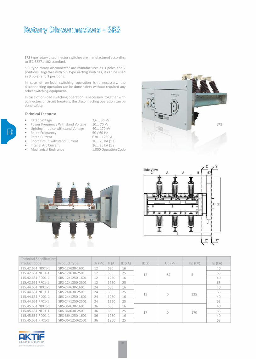
SRS type rotary disconnector switches are manufactured according to IEC 62271-102 standard.
SRS type rotary disconnector are manufactures as 3 poles and 2 positions. Together with SES type earthig switches, it can be used as 3 poles and 3 positions.
In case of on-load switching operation isn’t necessary, the disconnecting operation can be done safety without required any other switching equipment.
In case of on-load switching operation is necessary, together with connectors or circuit breakers, the disconnecting operation can be done safety.
Technical Features:• Rated Voltage : 3,6... 36 kV• Power Frequency Withstand Voltage : 10... 70 kV• Lighting Impulse withstand Voltage : 40... 170 kV• Rated Frequency : 50 / 60 Hz• Rated Current : 630... 1250 A• Short Circuit withstand Current : 16… 25 kA (1 s)• Intenal Arc Current : 16… 25 kA (1 s)• Mechanical Endırance : 1.000 Operation Cycle
SRS
Technical SpecificationsProduct Code Product Type Ur (kV) Ir (A) Ik (kA) tk (s) Ud (kV) Up (kV) Ip (kA)115.42.651.ND01-1115.42.651.NF01-1115.42.651.RD01-1115.42.651.RF01-1115.44.651.ND01-1115.44.651.NF01-1115.44.651.RD01-1115.44.651.RF01-1115.45.651.ND01-1115.45.651.NF01-1115.45.651.RD01-1115.45.651.RF01-1
SRS-12/630-1601SRS-12/630-2501SRS-12/1250-1601SRS-12/1250-2501SRS-24/630-1601SRS-24/630-2501SRS-24/1250-1601SRS-24/1250-2501SRS-36/630-1601SRS-36/630-2501SRS-36/1250-1601SRS-36/1250-2501
121212122424242436363636
630630125012506306301250125063063012501250
162516251625162516251625
406340634063406340634063
12 87 5
15 0 125
17 0 170

41
Earthing Switches - SES
SES series earthing switches are used for earthing the medium voltage systems in safety.
SES series earthing switches can operate with all type of disconnector mechanisim. Due to the air insulated type, disconnector contact position can be observed easly.
SES series earthing switches are manufactured according to class E2-B to have 5 times making capacity.
SES series earthing switches are manufactured according to IEC 62271-102 stamdard.
Technical Features:• Rated Voltage : 3,6... 36 kV• Power Frequency Withstand Voltage : 10... 70 kV• Lighting Impulse Withstand Voltage : 40... 170 kV• Rated Frequency : 50 / 60 Hz• Short Circuit Withstand Current : 16… 40 kA • Rated Short Circuit Withstand Time : 1s and 3s• Mechanical Endurance : E2-B
Technical SpecificationsProduct Code Product Type Ur (kV) Ik (kA) tk (s) Ud (kV) Up (kV) Ip (kA)115.42.758.0D01-1115.42.758.0E01-1115.42.758.0F01-1115.42.758.0H01-1115.44.758.0J01-1115.44.758.0D01-1115.44.758.0E01-1115.44.758.0F01-1115.45.758.0H01-1115.45.758.0J01-1115.45.758.0D01-1115.45.758.0E01-1115.45.758.0F01 -1115.45.758.0H01-1
SES-12/0000-1601SES-12/0000-2001SES-12/0000-2501SES-12/0000-3101SES-12/0000-4001SES-24/0000-1601SES-24/0000-2001SES-24/0000-2501SES-24/0000-3101SES-24/0000-4001SES-36/0000-1601SES-36/0000-2001SES-36/0000-2501SES-36/0000-3101
1212121212242424242436363636
16202531,54016202531,54016202531,5
405063801004050638010040506380
3 28 75
3
3
50 125
70 170
SES

42
Product Advantages:• Quick and easier detection of fault location • Limitaion the fault currents• Protection agaginst transient voltage• Large product range from low voltga level to high voltage level• Design quality• Design and production in complience with standards
Technical Features:• Rated Voltage• Fault Current• Fault Duration
Neutral Grounding Resistors - SRG
Short circuits between phase and ground cause high fault currents that results irreversible damages in the systems and Networks. Neutral grounding resistors avert these damages by limiting the fault current.
Neutral grounding resistors are used in industry by connecting to the star points of the generators or transformers.
Grounding through a resistor has several advantages with respect to other methods (such as insulated grounding, direct grounding or grounding through a reactance). These advantages are easier detection of fault location, limitation of fault current and no transient over current.
SRG series neutral grounding resistors are used in substations, hydroelectrical power plants, wind power plants.
SRG
SRG

43
Load Banks - SRL
SRL Series single or three phase, manual or automatic Load Banks allow to effectively check the efficiency of emergency sets (such as generators, uninterrupted power supplies, etc.) and can be employed as dummy loads to prevent wet stacking on diesel engines. They represent a reliable and economic way to prolong the lifetime of extremely expensive and important equipments.
Product Advantages:• Generators and UPS’ can be tested in safe• Diesel motors are protected against to open circuit operation• Provides proper load step by PLC • Design quality• Design and production in complience with standards
Essential information needed to design a Load Bank is:
• Rated voltage,• Phases,• Power,• Number and type of steps, if any• Type of ventilation (natural or forced)
SRL
Single Phase General Layout

44
Compact Substations made by Steel Sheet - SCK ................................................................................................ 46Compact Substations made by Concrete - SMK ................................................................................................... 47Compact Solar Substations - RST .......................................................................................................................... 48Mobile Substations - SMS .................................................................................................................................... 49
MV Substations

45
EMV Substations
Building
Industry
Energy

46
Compact Substations made by Steel Sheet - SCK
SCK-1 series compact substations are made by galvanized sheet steel with requested dimensions and manufactured according to IEC 62271-202 standard.
Product Advantages:• Internal arc classification in compliance with IAC A and B• IP23D protection class• Galvanized steel sheet construction, hot-dip galvanized steel frame, electrostatic powder coat and NPU base profiles • Optional HVAC, fire detecting and extinguisher system• Suitable design for each type LV and MV panels.
Technical Features:• Altitude : 1000 m• Ambient temperature : -5 ... +50 °C• Pollution degree : Class 3• Maximum Solar Radiation : 1000 W/m2
• Earthquake Resistance : 0,5 g horizontal and vertical• Inner wall thickness : 1 mm Galvanized steel sheet• Outer wall thickness : 2 mm Galvanized steel sheet• Frame thickness : 3 mm Hot-dip Galvanized steel sheet• Wall Thickness : 40 mm• Insulation material : EPS (Expanded Polystyren Foam) • Insulation density : 1,8 kg/mᶟ• Incombustibility degree : E• R Value : 7
SCK-1
SCK-2 series compact substations are produced in compliance with Zone 2 area conditions for Oil & Gas applications according to IEC 62271-202
Product Advantages:• Internal arc classification in compliance with IAC A and B• Protection class from IP23D up to IP54 • Suitable insulation material to ambient conditions • NPU or NPI base profiles made by hot-dip galvanized against corrosion• Doors can be opened 120° outside and designed against to 20 J mechanical shock• Rubber floor covering at level of 50kV and has A1 incombustibility degree • HVAC, fire detecting and extinguisher system • Special design and production to application
Technical Features:• Altitude : 1000 m• Ambient Temperature : -25 ... +50 °C• Earthquake Resistance : 0,5 g horizontal and 0,4 g vertical• Ur : max 40,5kV• Fr : 50/60 Hz• IAC : A and B• IP : up to IP54• Hazerdous Area : Zone2
SCK-2

47
Compact Substations made by Concrete - SMK
SMK series monoblock concrete kiosks are transformer and distribution substations manufactured up to 1600 kVA transformer power.
SMK series monoblock concrete kiosks are manufactured in compliance with type tests received international accredited laboratories, IEC 62271-202 standards and TEDAŞ MYD standards.
Product Advantages:• Modular design• Operation in safety • Easy transport and start up• Long service life• High strength due to C35 concrete• Internal arc classification in compliance with IAC A and B• Safety and tested earthing circuits• Different product solutions to special projects• Suitable design for each type LV and MV panels.
Technical Features:• Altitude : 1000 m• Ambient temperature : -5 ... +50 °C• Pollution degree : Class 3• Maximum solar radiation : 1000 W/m2• Earthquake Resistance : 0,5 g horizontal and vertical• IAC : A and B• IP : IP23D• Cl : 10• Compressive strength class : C35
SMK
SPK series prefabricated concrete kiosks are transformer and distribution substations manufactured up to 2500 kVA transformer power.
SPK series prefabricated concrete kiosks are manufactured in compliance with type tests received from international accredited laboratories, IEC 62271-202 standards and TEDAŞ MYD standards.
Product Advantages:• Easy assembly and disassembly on site• High strength due to C35 concrete• Internal arc classification in compliance with IAC A and B• Safety and tested earthing circuits• Suitable depth dimensions for installment metal clad switchgear• Different product solutions to special projects• Manufacturing in compliance with internal arc test received from accredited laboratories• Suitable design for each type LV and MV panels.
Technical Features:• Altitude : 1000 m• Ambient temperature : -5 ... +50 °C• Pollution degree : Class 3• Maximum solar radiation : 1000 W/m2
• Earthquake Resistance : 0,5 g horizontal and vertical• IAC : A and B• IP : IP23D• Cl : 10• Compressive strength class : C35
SPK

48
Compact Solar Substations - RST
The RST Line Compact Station represents a unique plug & play solution already assembled and tested in the factory. It is ready to be transported and installed on-site, connected through the string boxes to the PV panels, then connected to the grid.
General Characteristics:
RECon RST-30H• Power steps for H; 374, 561, 748, 935 and 1122 kWp.• Power steps for H1; 416, 624, 832, 1040, 1248, 1664, 2080 and 2496 kWp.• According to grid rated voltage.
RECon RST-2.30H• Power steps for H; 374, 748, 1122, 1496, 1870 and 2244 kWp.• Power steps for H1; 416, 832, 1248, 1664, 2080 and 2496 kWp.• According to grid rated voltage.
Product Advantages:• More Than Sixty Years Experience in Manufacturing.• High Maximum (99,3%) and Euro (98,7%) Efficiency Values.• High Efficiency Thanks to The Climate Control System (< 30⁰C).• Supplier to End User Unique Plug & Play Solution.• Reduced The Costs of Engineering, Transportation and On-Site Installation.• Compact Design for Easy Maintenance and Service.
RST 30H1
RECon RST

49
Mobile Substations - SMS
SMS series mobile substations are transformer and distribution substations on mobile platforms .
SMS series mobile substations are used for applications like temporary power demands, mining applications, military camps, industrial facilities, emergency power demands and additional power requests.
SMS series mobile substations can be installed on trailer, platform, wagon, vessel according to the application and HV switching equipment can be chosen as gas insulated or air insulated. Complete substation can be equipped with remote control systems. SMS series mobile substations can be produced in a short time and low cost in comparison with fixed type substations.
Product Advantages:• Mobile design• Operation in safety• Easy and quick transport and installment• Special design solutions for different applications• Diffferent applications on trailer, platform, wagon, vessel • Quick solution for emergency power or additional power requests
Technical Features:• SMS 1 : 3.6 – 40.5 kV / 0.23 - 0.69 kV, 50/60 Hz, 0.5 - 4 MVA• SMS 2 : 3.6 – 40.5 kV / 1 - 24 kV, 50/60 Hz, 1 – 31.5 MVA• SMS 3 : 52 - 245 kV / 3.6 - 10.5 kV, 50/60 Hz, 1 - 45 MVA
SMS series

50
Modular Type Solar Inverters ...................................................................................................................................... 52String Boxes ................................................................................................................................................................. 53
Power Converters

51
FPower Converters
Building
Industry
Energy
Traction
Medical Plants

52
Modular Type Solar Inverters
Recon Line 30 modular inverters represents optimum solutions for LV and HV grid applications such as mid-sized and large renewable power plants with step-up transformers.
Product Advantages:• More Than Sixty Years Experience in Manufacturing,• High Maximum and Euro Efficiency Values,• Parallel Modules or Independent Modules Configurations, • Easy Maintenance Thanks to Withdrawable Power Section,• Event Recording, Load Profile and Oscyllograph,• Touchscreen Panel for Easy Access to Parameters,• USB, Second Serial RS485, RS232 and Ethernet Ports.
General Characteristics
RECon 30L• Power steps for 30L; 100, 200, 300, 400, 500 and 600 kW.• Power steps for 30L1; 125, 250, 375, 500, 625 and 750 kW.• Rated output voltage; 200 VAC for 30L, 250 VAC for 30L1. RECon 30H• Power steps for 30H; 150, 300, 450, 600, 750 and 900 kW.• Power steps for 30H1; 167, 334, 501, 668, 835 and 1002 kW.• Rated output voltage; 300 VAC for 30H, 330 VAC for 30H1.
RECon 2.30• Power steps for 2.30H; 300, 600 and 900 kW.• Power steps for 2.30H1; 334, 668 and 1002 kW.• Rated output voltage; 300 VAC for 2.30H, 330 VAC for 2.30H1.
The Central Inverters are the first born and represent the flagship of RECon Line. The line has been developed following FRIEM’s traditional concepts of reliability, efficiency and modularity, devoted to high flexibility and easy maintenance.
Our RECon Central Inverters have modular and compact design; they can be used as single unit or combined in parallel to reach the requested power. From one single module up to six modules, starting from 100kWp up to 1470kWp, with 100% independent operation of each module.
Thanks to the modularity, each Inverter can manage more than one independent subfield with different irradiation and exposition, with multiple MPPTs (up to 6 MPPTs for MW A.C.).
Fully automated Regulation performing, Control and Protection, highest conversion efficiency, Standard Modbus-RTU communication protocols and a touch screen operator panel, are definitively value added features. With 20 years life design, and industrial design suitable for hard environments, FRIEM’s Inverters ensure easy maintenance and quick replacement of the main components, granting the possibility of easy onsite maintenance and simplified spare parts management.
The complete Removable Inverter Board can be replaced in only 1 hour, ensuring full reliability and continuity of production. All the different models of the RECon Line have been tested and certified according to IEC Standards and CE Directive, UL and CEC.
RECon 2.30H-1 1227

53
FRIEM string box enables the parallel connection up to 36 inputs through a disconnecting switch, are connected to the Inverter.The string box has also an overvoltage protection device. The continuous measurement of the current for each string, of the irradiation and temperature of the panels (through dedicated sensors), allows a complete check of the operation of the solar modules.
A transmission of measures and of protection’s status through serial communication with the inverters are integrated in the monitoring system.
The cover of the string box is realized in strong, weatherproof, polyester laminated glass with IP65 protection degree suitable for indoor and protected outdoor installation.
String Boxes
STR string box enables the parallel connection of 8 (STR-8),12 (STR-12), 16 (STR-16), 18 (STR-18) or 36 (STR-36) strings, which, through a disconnecting switch, are connected to the Inverter.The string box has also an overvoltage protection device.
General Characteristics: ● Number of Current Inputs : 8 – 12 – 16 – 18 – 36 ● DC Maximum Voltage : 1000 Vcc ● DC Maximum Output Current : 128 – 384 Acc ● Short Circuit Maximum Current : 192 – 512 Acc ● DC Fuses (positive pole) : 12 – 15 Acc / 1 kVcc ● DC Fuses (negative pole) : 12 – 15 Acc / 1 kVcc (Optional) ● Withdrawable Fuse Holder : Var ● AUX Power Supply : 230 Vac +/- +10
Models: ● STR-n : String Box with n Current Input (Base Model) ● STR-n .F : String Box with n Current Input + Fuses On Both Poles ● STR-n.D : String Box with n Current Input + Diodes ● STR-n.C : String Box with n Current Input + Fast-On Connectors ● STR-n .BI : String Box with n Current Input + Shunt Release ● STR-n.BV : String Box with n Current Input + U/V Release ● STR-n.A : String Box with n Current Input + Self Powered ● STR-n.S : String Box with n Current Input Without Measurement
n= Number of inputs string box 8, 12, 16, 18 veya 36.
Not: All the options can be combined when ordered.
STR String Box

54
Traction Rectifiers ..................................................................................................................................... 56DC Circuit Breaker Cubicles ....................................................................................................................... 57Disconnecting Cubicles ............................................................................................................................. 58Track-side and Depot Disconnecting Cubicles ............................................................................................ 58Negative Voltage Limiting Devices ............................................................................................................. 59
Traction Power Distribution

55
GTraction Power Distribution
Building
Industry
Energy
Traction
Solar Systems
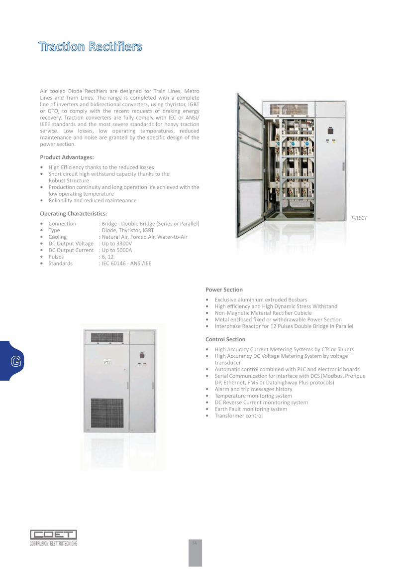
56
Power Section• Exclusive aluminium extruded Busbars• High efficiency and High Dynamic Stress Withstand• Non-Magnetic Material Rectifier Cubicle• Metal enclosed fixed or withdrawable Power Section• Interphase Reactor for 12 Pulses Double Bridge in Parallel
Control Section• High Accuracy Current Metering Systems by CTs or Shunts• High Accurancy DC Voltage Metering System by voltage transducer• Automatic control combined with PLC and electronic boards• Serial Communication for interface with DCS (Modbus, Profibus DP, Ethernet, FMS or Datahighway Plus protocols)• Alarm and trip messages history• Temperature monitoring system• DC Reverse Current monitoring system• Earth Fault monitoring system• Transformer control
Traction Rectifiers
Air cooled Diode Rectifiers are designed for Train Lines, Metro Lines and Tram Lines. The range is completed with a complete line of inverters and bidirectional converters, using thyristor, IGBT or GTO, to comply with the recent requests of braking energy recovery. Traction converters are fully comply with IEC or ANSI/IEEE standards and the most severe standards for heavy traction service. Low losses, low operating temperatures, reduced maintenance and noise are granted by the specific design of the power section.
Product Advantages:• High Efficiency thanks to the reduced losses• Short circuit high withstand capacity thanks to the Robust Structure• Production continuity and long operation life achieved with the low operating temperature• Reliability and reduced maintenance
Operating Characteristics:• Connection : Bridge - Double Bridge (Series or Parallel)• Type : Diode, Thyristor, IGBT• Cooling : Natural Air, Forced Air, Water-to-Air• DC Output Voltage : Up to 3300V• DC Output Current : Up to 5000A• Pulses : 6, 12• Standards : IEC 60146 - ANSI/IEE
T-RECT

57
DC Circuit Breaker Cubicles
DC Metal Clad Switchgears are designed for Industrial application with the switching capacity of 750 V/1500 V/3000 Vdc up to 10.000 A.
In the mass production the DC Switchgears are conforming the IEC standards as well as conforming other standards if required.
Metal Clad Switchgears has 4 accessible compartments
• Low Voltage Compartment• High Speed Circuit Breakers compartment• Cable Compartment• Busbar Compartment
DC Metal Clad Switchgears can be continue to operation in three positions (service/test/withdrawn). As additionally Switchgears has the Interlocking system against the miss operation.
DC Switchgears are suitable for below applications according to the EN 50123, IEC77, ANSI C 37-14, ANSI C37-16 standards.
• Up to 10.000 A in 750 Vdc systems• Up to 10.000 A in 1200 Vdc systems• Up to 8.000 A in 1500 Vdc systems• Up to 3.000 A in 3000 Vdc systems
NCA 1500

58
Disconnecting Cubicles
In DC Traction applications one disconnect or load break switch normally installed downstream each High Speed Circuit Breakers, and for the security reasons one motorized load break switch installed as parallel.
To comply with these requirements LBD panels developed which offers a very versatile and compact design. According to the requirements the LBD panel can be supplied as motorized and remote controlled.
Segragated compartment for each Disconnector and/or Load Break Switch and for each cable incoming/outgoing. Withdrawable execution on request.
Segragated low voltage compartments including protective relays and PLC/RTU for SCADA connection in cable or fiber optic. Motor or manuel operated Switches with manuel emergency operation. Main contact position visibility.Voltage presence relays and surge arrestors are available in the panels.
Technical Features:• Rated Voltage : 750 - 1500 - 3000 Vdc• Rated Insulation Voltage : 4,8 kV• Rated Impulse Voltage : 48 kV• Rated Current : 3000 - 4000 A• Breaking Capacity : 3000 - 4000 A• Making Capacity : 100 kA• Rated short-circuit Current (0,1ms) : 100 kA
LBD
Track-side and Depot Disconnecting Cubicles
Equipped with motorized disconnectors or Load Break Switches. The track side and depot disconnecting units allow isolating portion of the track systems.
Available for different executions as Indoor, Outdoor, Pole mounting and are suitable for tram, metro, trolley bus and railway applications. Also suitable for the mounting in the town and tunnel alcoves. They used to automatic earthing of the line.
Equipped with Voltage presence relay.Motor control with manual emergency operation possibilities. Two poles version for positive and negative isolation. Remote control through PLC, Modem and GSM radio and battery with self powered recharge on request.
Depends on the requirements self powered version is available.
Technical Features:• Rated Voltage : 750 - 1500 - 3000 Vdc• Rated Insulation Voltage : 4.8 kV• Rated Impulse Withstand Voltage : 48 kV• Rated Current : 1250 - 1800 - 3400 A• Rated short-circuit Current (0,25s) : 50 kA

59
Negative Voltage Limiting Devices
For the security reason, the negative panels has an earthing position visible from outdoor and lockable for negative maintanence at the Substations or at lines of the Traction applications.
Negative Panels are consisting of earthing disconnector, transducers and the measuring instruments.
Negative panel are integrated with over current relays and some applications with over voltage relays where the Negative panels includes OVPD.
Technical Properties:• Rated Voltage : 750 - 1500 - 3000 Vdc• Making Capacity : 35 - 50 - 100 kA• Rated Insulation voltage : 4.8 kV• Rated Impulse Voltage : 40 kV• Insulation Class : IP30
LBR-n
OVPD
As indicated in the EN 50122-1 and 2 standards, the negative circuit must not be connected to the earth but it must connected to the short circuiting when the voltage limit value is dangerous.
SCR static switch for fast operation ( <1ms ) when the voltage exceeds the dangerous level of 300 V or 600 V.For the security reason the device earthing position visible from outdoor and lockable for negative maintenance. OVPD panels are integrated with over voltage protection relays and self test functions.

AMDT
- Ge
nera
l Cat
alog
201
614/
Eng.
Akşemsettin Mh. Çatalca sk. No:113 06930 Sincan Ankara - TürkiyeTel : +90 (312) 269 46 02 Fax : +90 (312) 269 45 01www.aktif.net - [email protected]
Bayraktar Blv. Şehit sk. No: 5 Aktif Plaza34775 Ümraniye İstanbul - TürkiyeTel : +90 (216) 314 93 20Fax : +90 (216) 314 93 60www.aktif.net - [email protected]
White…Color of the beginning…White, color of the purity, honesty and clarity…
Color of the stability and continuity, trust and quality…
Since 2010, we decided to apply white color which symbolizes all of these values to all of our products.