Embed Size (px)
Citation preview

GE Oil & Gas
Andco* ActuatorsPrecise positioning and reliable automation for controlled motion

Table of Contents
Overview ...................................................................................................................................3Eagle Linear Actuator ............................................................................................................47000 Series Linear Actuator .................................................................................................68000 Series Linear Actuator ...............................................................................................15QR & QRG Rotary Actuator..................................................................................................19Standard Options Mounting: Clevis, Trunnion, Flange ...........................................................................24 Manual Override ............................................................................................................24 Extension Rod Cover .....................................................................................................25 Adjustable Gear Driven Position Limit Switch ........................................................25 Gear Driven Potentiometers .......................................................................................25 Electric Motor Brake .....................................................................................................26 Single Phase Electronic (Dynamic) Motor Braking .................................................26 Single Phase Solid State Reversing Starter/Programmable Controller Interface ....................................................................................................26 Three Phase Motor Control .........................................................................................26 Model 4100 Position Indicating Meter ......................................................................27 Push button/Selector Switch Station ........................................................................27 Three Phase Motor Control .........................................................................................27 Positran® Transmitter ..................................................................................................27Controls 5100 Position/Process Control ...................................................................................28 EASC - Electric Actuator Smart Control ....................................................................30 Profibus DP® ...................................................................................................................32 DeviceNet™ ......................................................................................................................33 Modbus® ..........................................................................................................................34

3
GE's Andco* electric linear and rotary actuators offer a superior technology choice when reliable, precise, controlled motion is required. Whether moving industrial doors, providing accurate positioning feedback for antennas, or modulating and controlling louver dampers, customers can rely on Andco actuator solutions.
The Andco actuator portfolio includes weatherproof and dustproof options, offering customers durability and performance in severe industrial environments, including hot and cold temperature extremes. Andco actuators are a superior solution for a range of functions including positioning, lifting/lowering, pushing/pulling, and opening/closing.
Andco actuator technology offers low maintenance packages with internal adjustable limit switches for on/off control and light indication, internal torque switch for overload protection, optional internal position/process controls for positioning, motor braking and motor control. Our actuator solutions deliver ease of installation, maintain constant output force and velocity, and consume power only during movement.

4
Eagle* Linear Actuators
Features ■ Non-rotating drive rod ■ Non-backdriving ■ All metal gearing ■ Compact with electromechanical repeatability ■ Simple to mount; easy to wire ■ Comparable cost to pneumatic or hydraulic systems ■ Equivalent in size to hydraulic or pneumatic cylinders ■ Operating range -40°F to +150°F
Temperature Range
Ambient -40°F to +150°F
-40°C to +65°C
Motor Data
115 VAC, 1 Phase, 2.6A1
230 VAC, 1 Phase, 1.12A1
230 VAC,3 Phase, .52A1
460 VAC, 3 Phase, .26A1
575 VAC, 3 Phase, .2A1
Class B Insulation
NEMA “D” design
Approvals
CSA available on select models
1 Full load current (Amps).
Standard Equipment ■ Thermal switch in motor winding ■ Two independently adjustable, gear driven position limit switches with all metal gearing
■ Nickel-plated drive rod ■ Clevis and pin on drive rod end ■ Nema 4 Weatherproof and/or Nema 4 Dust-Ignition proof enclosure (Class II, Division 1, Groups E, F and G)
■ Anti-friction bearings on all drive components ■ All metal gearing ■ Cast aluminum construction ■ Clevis mount on the motor end ■ Permanently lubricated for maintenance-free operation
■ Heavy duty industrial motor; 115 VAC, 60 Hz, single phase,TENV, permanent split capacitor, high starting torque, low inertia
Optional Equipment ■ 230 VAC, 460 VAC and 575 VAC, 60 Hz, 3 phase motor
■ Potentiometer (all metal gear driven) ■ Integral position process control board for modulating applications
■ 4-20mA position transmitter ■ Adjustable trunnion mount and trunnion brackets ■ Adjustable face/flange mount ■ Manual override
The Andco Eagle Linear Actuator is a completely self-contained electro-mechanical device. Its compact design is equivalent in size to hydraulic or pneumatic cylinders. Designed and fabricated for easy installation and dependable long-life operation, these actuators are driven by a high starting torque motor with thermal overload protection, non-rotating extension rod, non-backdriving acme screw and all metal gearing.

5
Dimensions
NOTES
1. Unbracketed dimensions are in inches
2. Bracketed dimensions are in millimeters
3. Dimensions shown with actuator fully retracted
4. Dimensions are for reference only. Please contact GE for
engineering drawings.
3100 Series
Velocity (in/sec)
Breakway Force (lbs)
Running Force (lbs at 5% duty)
Weight Range
(lbs)
Stroke (in)
0.20.40.82.0
20001500750500
1000750340200
35-756,128, 24
30 & 36
“T” Adjustable Dimension
Stroke Inches Millimeters
6 2.38 - 2.88 (60.45 - 73.15)
12 2.38 - 8.00 (60.45 - 203.20)
18 2.38 - 14.00 60.45 - 355.60)
24 5.38 - 20.00 (60.45 - 508.00)
30 11.38 - 26.00 (12.85 -660.40)
36 17.38 - 32.00 (365.25 - 812.80)
Eagle Electrical Cylinder Performance Adjustable Trunnion or Face/Flange
2.00(50.8)
Adjustable Face/Flange Mount (optional)(Viewed facing Drive Rod end of Actuator)
1.00(25.4)
.75(19)
.56 dia. hole(14.3) 4 places
4.25 dia. B.C.(108.0)
.75(19)
3.65(92.6)
2.56(65.1)
3.41(86.7)
3/4 NPT conduitentrance, 2 places
2.25 dia.(57.2)
7.47(189.7)
2.88(47.8)
.53 dia. hole(13.6) 4 places
8.33(211.6)
.50 dia.Clevis pin
(12.7)
8.18(207.8)
9.90(251.3)
2.44(61.9)
2.44(61.9)
8.19(208)
Clevis Mount Hole
.502 – .505 dia.(12.75 – 12.83)
Slotted shaft for manual operation for limit switch adj.
“T”Flange Mount
Adjustable trunnion or face/flange mount (optional)
Limit switch and potentiometer compartment
8.31 + stroke (± .13 for adj.)(2.11)
1.11(28.2)
1.0(25.4)
1.59(40.3)
Hexacross corners
“T”Trunnion Mount
1.0(25.4) 2.38
(60.5)
.88(12.8).5 dia. Trunnion pins
(12.7)

6
The Andco 7000 Series linear actuator is a completely self-contained, electro-mechanical device. Designed and fabricated for dependable, long-life operation, these actuators are used for positioning, automation of material handling, or flow control equipment.
7000 Series actuators are driven by a high starting torque, low inertia motorconnected to a drive screw through a set of gears. When the motor rotates the drive screw, the mating nut and attached extension rod move axially.
Upon completion of stroke, the gear driven position limit switch interrupts power to the motor. If movement of the extension rod is prevented in either direction at any point in actuator travel due to an external mechanical overload, a thrust switch will interrupt power to the motor.
1. High strength ground and plated extension rod 2. Front end cap with bearing support, rod wiper and grease seal 3. Four tie-rod construction with guided drive nut 4. Thrust limit disc springs and spring limit sleeve to prevent total
spring deflection 5. Anti-friction bearings 6. High strength alloy steel cut gears 7. Gear driven potentiometer or encoder drives available 8. Heavy duty motor, TENV, NEMA D design, high starting torque, low inertia
motor provides high breakaway forces and good positioning characteristics; Class F insulation is standard
9. Versatile mounting, clevis (7100 only), trunnion or face/flange
1
2
3
11
7000 Series Linear Actuators

7
10
7
11
4
5
68
9
10. A two position gear driven position limit switch for end-of-travel actuator shutoff and a set of contacts for light indication are included as standard. Each position is independently adjustable and can be set anywhere within the full actuator travel. The heavy duty rotary drum, double break switch with wiping contacts feature a patented mechanism that ensures internal gear engagement after adjustment.
11. An adjustable thrust switch for each direction of travel is provided as standard. The switch assembly will automatically shut off the actuator if the set force is exceeded. The switch protects driven equipment from damage due to excessive forces and can also be used as a mechanism for positive seating.
Other Features ■ Weatherproof or Dust-Ignition Proof Enclosure (Class II, Divisions 1, Groups E, F, and G)
■ Plated external hardware ■ Permanently lubricated ■ Non-backdriving acme screw ■ Efficient ball screws with motor brake ■ Electrical components are prewired and terminated inside the actuator
Temperature Range
Ambient -30°F to +120°F
-34°C to +48°C
Motor Data
115 VAC, 1 Phase
230 VAC, 3 Phase
460 VAC, 3 Phase
575 VAC, 3 Phase
Class F Insulation
NEMA “D” design
Approvals
CSA available on select
models1
1 Not available on 7400 or 7500 models.

8
7000 Series Linear Actuators7000 Series Acme Screw Linear Actuators
ModelVelocity(in/sec)
Breakaway Thrust Rating
(lbs)
Running Thrust Rating (lbs)Stroke Range
(ins)
Approximate Weight Range
(lbs)5% Duty 10% Duty 25% Duty
7102S (1-Phase)
0.8 975 450 330 130
6-24 50-801.1 750 325 240 95
2.0 410 175 135 50
2.8 290 125 90 35
7105T
1.1 2,100 650 240 95
6-24 45-80 2.0 1,225 350 135 50
2.8 875 250 90 35
7202S(1-Phase)
1.1 750 330 330 260
6-36 55-100 1.5 460 240 240 180
2.8 300 130 130 100
4.0 215 90 90 70
7205T
1.5 1,700 480 460 –
6-36 50-100 2.8 900 260 255 –
4.0 650 185 180 –
7210T
1.5 2,100 1,000 – –
6-36 50-100 2.8 1,815 510 – –
4.0 1300 370 – –
7310T
1.4 2,530 1,100 1,050 525
6-60 85-185 2.1 1,750 700 700 350
3.2 1,130 455 455 225
7317T 2.1 4,220 1,300 1,300 –
6-60 100-200 3.2 2,750 850 520 –
7324T 2.0 5,900 1,750 – –
6-60 100-200 3.2 3,800 1,250 – –
74-7330T 2.8 5,200 2,850 – –
6-60 120-240 3.6 4,000 2,200 – –
7000 Series Acme Screw Linear Actuators with Gearbox Assembly
ModelVelocity(in/sec)
Breakaway Thrust Rating
(lbs)
Running Thrust Rating (lbs)Stroke Range
(ins)
Approximate Weight Range
(lbs)5% Duty 10% Duty 25% Duty
7202S (1-Phase)
0.2 2,100 1,100 1,100 1,100 6-36 65-110
7205T 0.5 2,100 1,100 1,100 1,100 6-36 65-110
7302S(1-Phase)
0.2 4,560 1,845 1,845 1,845
6-60 95-190 0.4 2,130 920 920 920
0.7 1,130 490 490 490
7305T 0.4 6,200 1,795 1,795 1,795 6-48 90-160
7324T 1.1 7,000 3,075 – – 6-48 115-205
74-7330T 1.5 7,000 5,100 – – 6-60 130-250

9
7000 Series Ball Screw Linear Actuators
ModelVelocity(in/sec)
Breakaway Thrust Rating
(lbs)
Running Thrust Rating (lbs)Stroke Range
(ins)
Approximate Weight Range
(lbs)5% Duty 20% Duty 40% Duty 60% Duty
7302S (1-Phase)
1.4 1,990 670 670 670 670
6-48 110-190
2.1 1,370 460 460 460 460
3.2 890 300 300 300 300
4.2 690 230 230 230 230
6.4 450 150 150 150 150
12.2 240 80 80 80 80
7301T
1.4 7,000 2,680 2,680 2,680 2,680
6-48 110-190
2.1 5,780 1,850 1,850 1,850 1,850
4.2 2,900 920 920 920 920
6.4 1,875 600 600 600 600
12.2 940 320 320 320 320
7317T
2.1 7,000 3,230 2,700 2,150 1,800
6-48 110-210 4.2 7,000 1,610 1,610 1,610 1,610
6.4 4,550 1,050 1,050 1,050 1,050
12.2 2,400 550 550 550 550
7324T
4.2 7,000 3,400 2,300 – –
6-48 120-260 6.4 6,600 2,200 1,500 – –
12.2 3,400 1,150 790 – –
7400 Series Ball Screw Linear Actuators
ModelVelocity(in/sec)
Breakaway Thrust Rating
(lbs)
Running Thrust Rating (lbs)Stroke Range
(ins)
Approximate Weight Range
(lbs)5% Duty 10% Duty 25% Duty
7430T 4.2 12,000 5,100 4,900 4,700 12-60 135-350
7450T 5.5 16,000 7,000 6,100 4,900 12-60 125-375
7500 Series Ball Screw Linear Actuators
ModelVelocity(in/sec)
Breakaway Thrust Rating
(lbs)
Running Thrust Rating (lbs)Stroke Range
(ins)
Approximate Weight Range
(lbs)5% Duty 10% Duty 25% Duty
7530T 2.0 24,000 12,000 11,000 10,000 12-60 275-575
7550T 2.0 42,000 20,000 16,000 12,500 12-60 275-625
NOTES
1 . The suffix S in the model number indicates a 115 VAC, 60 Hz single phase motor. 220 VAC, 60 Hz single phase is optional.
2. The suffix T in the model number indicates a 230 or 460 VAC, 60 Hz three phase. 380 VAC, 50 Hz and 575 VAC,
60 Hz are optional.
3. Strokes are available in 6 inch increments up to 36 inches and 12 inch increments up to 60 inches.
4. All stroke lengths can be adjusted downward with the position limit switch.
5. The information contained herein is in effect at the time of printing and the company reserves the right to make changes.
7000 Series Linear Actuators

10
Model6” Stroke 12” Stroke 18” Stroke 24” Stroke 30” Stroke 36” Stroke 48” Stroke 60” Stroke
A B A B A B A B A B A B A B A B
7102S 26.32 18.14 32.32 24.14 38.32 30.14 44.32 36.14 – – – – – – – –
7105T 25.32 18.14 31.32 24.14 37.32 30.14 43.32 36.14 – – – – – – – –
7202S 26.17 18.58 32.17 24.58 38.17 30.58 44.17 36.58 50.17 42.58 56.17 48.58 – – – –
7205T 25.17 18.58 31.17 24.58 37.17 30.58 43.17 36.58 49.17 42.58 55.17 48.58 – – – –
7210T 26.17 18.58 32.17 24.58 38.17 30.58 44.17 36.58 50.17 42.58 56.17 48.58 – – –
7310T 32.45 24.88 38.45 30.88 44.45 36.88 50.45 42.88 56.45 48.88 62.45 54.88 74.45 66.88 86.45 78.88
7317T 32.88 24.88 38.88 30.88 44.88 36.88 50.88 42.88 56.88 48.88 62.88 54.88 74.88 66.88 86.88 78.88
7324T 33.82 24.88 39.82 30.88 45.82 36.88 51.82 42.88 57.82 48.88 63.82 54.88 75.82 66.88 87.82 78.88
74-7330T 39.30 29.36 45.30 35.36 51.30 41.36 57.30 47.36 63.30 53.36 69.30 59.36 81.30 71.36 93.30 83.36
7000 Series Acme Screw Linear Actuators
Model C D E F G H J K L M1 M2 N P R S
7102S2.50 .375 .38 2.53 1.00 .38 1.63 0.94 2.32
8.186.00 1.60 2.65 3.60 4.68
7105T 7.18
7202S
2.75 .500 .50 2.40 1.00 .50 1.63 0.94 2.32
7.59
6.00 1.60 2.65 3.60 4.687205T 6.59
7210T 7.59
7310T
3.88 .750 .63 4.32 1.13 .75 2.25 3.29 4.72
7.57 6.00
2.00 2.82 4.19 5.187317T 8.00 6.86
7324T 8.94 6.86
74-7330T 4.38 1.25 1.26 6.13 2.00 1.25 3.25 3.29 4.72 9.94 6.86 2.00 2.82 4.19 5.18
Model6” Stroke 12” Stroke 18” Stroke 24” Stroke 30” Stroke 36” Stroke 48” Stroke 60” Stroke
A B A B A B A B A B A B A B A B
7102S 30.88 18.58 36.88 24.58 42.88 30.58 48.88 36.58 54.88 42.58 60.88 48.58 – – – –
7205T 29.88 18.58 35.88 24.58 41.88 30.58 47.88 36.58 53.88 42.58 59.88 48.58 – – – –
7302S 37.63 24.88 43.63 30.88 49.63 36.88 55.63 42.88 61.63 48.88 67.63 54.88 79.63 66.88 91.63 78.88
7305T 36.63 24.88 42.63 30.88 48.63 36.88 54.63 42.88 60.63 48.88 66.63 54.88 78.63 66.88 90.63 78.88
74-7330T 53.20 29.36 59.20 35.36 65.20 41.36 71.20 47.36 77.20 53.36 83.20 59.36 95.20 71.36 107.20 83.36
7000 Series Screw Linear Actuators with Gearbox Assembly
7000 Series Linear Actuators

11
7000 Series Acme Screw Linear Actuators
Series N1 N2 N3
7100 1” - 20UN 1.00 1.187
7200 1-1/4” - 20UN 1.12 1.433
7300 1-5/8” - 16UN 1.18 1.860
74-7300 1-1/8” - 16UN 2.06 2.350
Model C D E F G H J K L M1 M2 N P R S
7102S 2.75 .50 .50 2.50 1.00 .50 1.63 .94 2.32
12.306.00 1.60 2.65 3.60 4.68
7205T 11.30
7302S 3.88 .75 .63 4.32 1.13 .75 2.25 3.29 4.72
12.75 6.00 2.00 2.82 4.19 5.18
7305T 11.75
74-7330T 4.38 1.25 1.26 6.13 2.00 1.25 3.25 3.29 4.72 2.00 2.82 4.19 5.50
NOTES
For trunnion, clevis, and face flange mount dimensions see pages
14 and 15. Dimensions are for reference only. Contact GE for
engineering drawings.
7000 Series Linear Actuators

12
7000 Series Ball Screw Linear Actuators
Model6” Stroke 12” Stroke 18” Stroke 24” Stroke 30” Stroke 36” Stroke 48” Stroke 60” Stroke
A B A B A B A B A B A B A B A B
7302S 40.50 27.70 46.50 33.70 52.50 39.70 58.50 45.70 64.50 51.70 70.50 57.70 82.50 69.70 – –
7301T 40.50 27.70 46.50 33.70 52.50 39.70 58.50 45.70 64.50 51.70 70.50 57.70 82.50 69.70 – –
7317T 40.83 27.70 46.83 33.70 52.83 39.70 58.83 45.70 64.83 51.70 70.83 57.70 82.83 69.70 – –
7324T 41.70 27.70 47.70 33.70 53.70 39.70 59.70 45.70 65.70 51.70 71.70 57.70 83.70 69.70 – –
7430T – – 65.10 50.10 71.10 56.10 77.10 62.10 – – 89.10 74.10 101.10 86.10 113.10 98.10
7450T – – 68.50 50.10 74.50 56.10 80.50 62.10 – – 92.50 74.10 104.50 86.10 116.50 98.10
7530T – – 82.40 58.60 88.40 64.60 94.40 70.60 – – 106.40 74.10 118.40 86.10 130.40 98.10
7550T – – 82.40 58.60 87.80 64.60 93.80 70.60 – – 105.80 74.10 117.80 86.10 129.80 98.10
Model C D E F G H J K L M1 N P R TC TG TH
7302S
3.88 0.750 0.63 4.00 1.13 0.75 2.25 3.29 4.72
12.80
2.00 2.82 4.19 0.875 1.19 6.507310T 12.80
7317T 13.13
7324T 14.00
7430T 4.38 1.250 1.26 6.13 2.00 1.25 3.25 3.29 4.72
15.00 2.00 2.82 4.19 1.000 1.50 7.50
7450T 18.40
7530T 6.50 1.500 1.54 5.75 2.38 1.75 4.56 3.29 4.72
23.80 2.00 2.82 4.19 1.750 2.50 10.00
7550T 23.20
Series N1 N2 N3
7200 1-1/4” - 20UN 1.12 1.43
7300 1-5/8” - 16 UN 1.18 1.86
7400 1-1/8” - 16UN 2.06 2.35
7500 2-1/2” - 16UN 2.75 3.00
NOTES
For trunnion, clevis, and face flange mount dimensions see pages
14 and 15. Dimensions are for reference only. Contact GE for
engineering drawings.
7000 Series Linear Actuators

13
Trunnion and Clevis Mounting
Series TA TB TC TD TE TF TG TH TJ TK
7100-A 0.63 3.50 0.50 4.00 1.88 0.53 0.75 4.75 7.47 9.25
7200-A 0.63 3.50 0.50 4.00 1.88 0.53 0.75 4.75 7.47 9.25
7300-A 0.75 4.66 0.87 7.56 5.50 0.66 1.19 6.50 9.50 11.25
74-7300-A 0.75 4.66 1.00 7.56 5.50 0.66 1.43 7.50 10.50 12.25
7300-B 0.75 4.66 0.87 7.56 5.50 0.66 1.19 6.50 9.50 11.25
7400-B 0.75 4.66 1.00 7.56 5.50 0.66 1.50 7.50 10.50 12.25
7500-B 1.50 6.00 1.75 8.50 6.00 1.06 2.50 10.00 14.50 17.00
Trunnion and Clevis Mounting
NOTES
1. An adjustable trunnion mount is standard on 7200, 7300, and 74-7300 Series actuators (optional on 7100).
For 7400 Series ball screw actuators with an adjustable trunnion mount use “T” dimension from the 7400 flange mount table.
Fixed location trunnion pins are standard on 7400 and 7500 Series actuators.
2. Trunnion brackets are optional on all models.
3. Actuators supplied with adjustable trunnion mounting are set at the maximum dimension unless otherwise specified.
4. Dimensions are for reference only. Contact GE for engineering drawings.
7000 Series Linear Actuators
Series6” Stroke 12” Stroke 18” Stroke 24” Stroke 30” Stroke 36” Stroke 48” Stroke 60” Stroke
MIN MAX MIN MAX MIN MAX MIN MAX MIN MAX MIN MAX MIN MAX MIN MAX
7100-A 6.63 7.63 11.63 13.63 16.63 19.63 19.63 25.63 – – – – – – – –
7200-A 6.63 7.63 11.63 13.63 16.63 19.63 19.63 25.63 25.63 31.63 31.63 37.63 – – – –
7300-A 10.00 11.50 13.50 17.50 17.00 23.50 21.00 29.50 26.00 35.50 32.00 42.50 38.00 53.50 44.00 65.50
74 -7300-A 12.00 14.25 17.00 20.25 20.00 26.25 23.00 32.25 26.00 38.25 32.00 44.25 38.00 56.25 44.00 68.25
7300-B 13.00 14.00 18.00 20.00 21.00 26.00 24.00 32.00 28.00 38.00 32.00 44.00 40.00 56.00 – –
7400-B – – 33.62 33.62 39.62 39.62 45.62 45.62 – – 57.62 57.62 69.62 69.62 81.62 81.62
7500-B – – 36.44 36.44 42.44 42.44 48.44 48.44 – – 60.44 60.44 77.44 77.44 84.44 84.44
“T” (Shown with actuator fully retracted)

14
7000 Series Linear Actuators
Series6” Stroke 12” Stroke 18” Stroke 24” Stroke 30” Stroke 36” Stroke 48” Stroke 60” Stroke
MIN MAX MIN MAX MIN MAX MIN MAX MIN MAX MIN MAX MIN MAX MIN MAX
7100-A 3.32 6.75 3.32 12.75 6.63 18.75 12.63 24.75 – – – – – – – –
7200-A 3.32 6.75 3.32 12.75 6.63 18.75 12.63 24.75 18.63 30.75 24.63 36.75 – – – –
7300-A 10.00 11.00 16.00 17.00 22.00 23.00 28.00 29.00 34.00 35.00 40.00 41.00 52.00 53.00 64.00 65.00
74 -7300-A 11.00 13.25 17.00 19.25 23.00 25.25 29.00 31.25 35.00 37.25 41.00 43.25 53.00 55.25 65.00 67.25
7300-B 12.00 13.50 18.00 19.50 24.00 25.58 30.00 31.50 36.00 37.58 42.00 43.50 54.00 55.50 – –
7400-B – – 20.00 24.00 25.00 30.00 30.00 36.00 – 38.00 43.00 40.00 46.00 43.00 50.00
Series FA FB FC FD FE FF FG
7100-A 1.00 2.00 4.25 5.50 0.56 1.00 4.00
7200-A 1.00 2.00 4.25 5.50 0.56 1.00 4.00
7300-A 1.50 3.00 5.75 7.00 0.69 1.38 4.00
74-7300-A 2.25 4.50 6.50 8.00 0.81 1.00 5.00
7300-B 1.50 3.00 5.75 7.00 0.69 1.38 4.00
7400-B 2.30 4.60 6.50 8.00 0.81 1.00 5.00
“T” (Shown with Actuator Fully Retracted)
Face/Flange Mounting
Face/Flange Mounting
NOTES
1. Face/flange actuator may be rotated 90° from arrangement shown.
2. Face/flange location is set at maximum dimension unless otherwise specified.
3. Dimensions are for reference only. Contact GE for engineering drawings.

15
8000 Series Linear ActuatorsElectric Linear Actuators
Standard Equipment The Andco 8000 Series linear actuator is a completely self-contained, electro-mechanical device, designed and fabricated for dependable long life operation. The Andco 8000 Series is weatherproof or dust-ignition proof (Class II, Division 1, Groups E, F and G).
The 8000 Series is driven by a high-starting torque motor connected to a drive screw through gearing. When the motor rotates the drive screw, the mating drive nut and attached extension rod move axially. The gear-driven position limit switch interrupts power to the motor upon completion of stroke.
If during actuator travel some external obstacle prevents the extension rod from moving, the thrust limit switch will interrupt power to the motor.
The 8400 and 8500 Series actuators contain an additional spring assembly to protect the actuator drive components from shock loads. When compressed, the inherent spring load will provide automatic compensation for wear, temperature change, or material compression.
Temperature Range
Ambient -30°F to +120°F
-34°C to +48°C
Motor Data
115 VAC, 1 Phase
230 VAC, 3 Phase
460 VAC, 3 Phase
575 VAC, 3 Phase
Class F Insulation
NEMA “D” design

16
8000 Series Linear Actuators8200 Series Acme Screw Linear Actuators
Actuator Thrust Rating (lbs)Stroke
Range (in)Approx. Weight
Range (lbs)
Velocityin/sec
Model 8202S Model 8205T
0 - 36 60 -120
Breakaway Running Breakaway Running
0.06 4000 2000 – –
0.12 2500 1800 – –
0.18 1700 1200 4000 2000
0.36 1100 700 3275 1800
8300 Series Acme Screw Linear Actuators
Actuator Thrust Rating (lbs)Stroke
Range (in)Approx. Weight
Range (lbs)
Velocityin/sec
Model 8302S Model 8305T Model 8310T
0 - 60 90 - 200
Breakaway Running Breakaway Running Breakaway Running
0.23 1375 975 4100 2450 7000 3000
0.50 – – 3000 1425 5700 2625
0.80 – – 1750 900 3300 1650
8400 Series Acme Screw Linear Actuators
Actuator Thrust Rating (lbs)Stroke
Range (in)Approx. Weight
Range (lbs)
Velocityin/sec
Model 8417T Model 8424T
0 - 60 120 - 250Breakaway Running Breakaway Running
0.3 10,275 5075 13,500 10,000
0.6 6,600 3000 9,300 5,900
8300 Series Ball Screw Linear Actuators1
Actuator Thrust Rating (lbs)Stroke
Range (in)Approx. Weight
Range (lbs)
Velocityin/sec
Model 8302S Model 8305T Model 8310T
0 - 48 110 - 200Breakaway Running Breakaway Running Breakaway Running
0.9 1125 650 3400 1600 6400 2900
1.6 – – 2000 1000 3750 1875
8400 Series Ball Screw Linear Actuators1
Actuator Thrust Rating (lbs)Stroke
Range (in)Approx. Weight
Range (lbs)
Velocityin/sec
Model 8410T Model 8417T Model 8424T
0 - 60 125 - 275
Breakaway Running Breakaway Running Breakaway Running
0.23 16,000 11,000 – – – –
0.5 12,000 5,500 16,000 9,200 – –
1.0 – – 13,300 5,400 16,000 10,700
1 Actuator has motor brake as standard.

17
8000 Series Linear Actuators8500 Series Ball Screw Linear Actuators
Actuator Thrust Rating (lbs)Stroke
Range (in)Approx. Weight
Range (lbs)
Velocityin/sec
Model 8517T Model 8524T
0 - 60 225 - 575
Breakaway Running Breakaway Running
0.50 20,600 9,200 27,000 18,300
1.0 – – 18,600 10,700
1.9 – – 9,300 5,350
8500 Series Ball Screw Linear Actuators with Gearbox
Actuator Thrust Rating (lbs)Stroke
Range (in)Approx. Weight
Range (lbs)
Velocityin/sec
Model 8510T Model 8517T Model 8524T
0 - 60 275 - 625
Breakaway Running Breakaway Running Breakaway Running
0.09 51,000 25,100 80,000 41,000 – –
0.15 – – 51,000 24,500 70,000 50,000
0.3 – – 25,800 12,300 35,000 25,0001 Actuator has motor brake as standard.
Standard Models 8200, 8300, 8400 and 8500 Series Ball Screw Linear Actuators
NOTES
1. Models 8202S and 8302S are 115 VAC, 60 Hz, single phase. All other models are 230/460 VAC, 60HZ, 3 phase.
2. All units are furnished with two adjustable thrust limit switches and a two position, one contact per position
gear-driven position limit switch as standard equipment.
3. Strokes are available in 6 inch increments up to 36 inches and 12 inch increments up to 60 inches.
4. Running forces are based on 5% duty cycle.
5. Do not use actuators above their rated duty cycles without consulting factory.
6. Dimensions are for reference only. Contact GE for engineering drawings.

18
Mod
elD
rive
Ty
pe
AB
CD
EM
1M
2FA
FBFC
FDFE
TATB
TCTD
TETF
TGTH
TJTK
Stro
ke“L
”“F
”“T
”
Min
Ma
xM
inM
ax
8202
S
8202
T
8205
T
Acm
e Sc
rew
1.00
0.50
.500
2.50
2.75
11.0
6
8.50
10.0
6
6.00
2.00
4.25
5.50
0.56
1.00
0.75
4.66
0.50
7.56
5.50
0.66
0.75
4.75
7.75
9.50
620
.15.
506.
505.
506.
50
1226
.110
.50
12.5
010
.50
12.5
0
1832
.115
.50
18.5
015
.50
18.5
0
2438
.118
.00
22.0
018
.00
22.0
0
3044
.120
.00
25.0
020
.00
25.0
0
3650
.122
.00
28.0
022
.00
28.0
0
8302
S
8305
T
8310
T
Acm
e Sc
rew
1.13
0.63
.750
4.32
3.88
11.0
6
10.0
6
11.0
6
6.00
3.00
5.75
7.00
0.69
1.38
0.75
4.66
.875
7.56
5.50
0.66
1.19
6.50
9.50
11.2
5
624
.29.
5010
.50
9.50
10.5
0
1230
.214
.50
16.5
014
.50
16.5
0
1836
.219
.00
22.0
019
.00
22.0
0
2442
.221
.00
25.0
021
.00
25.0
0
3048
.223
.00
28.0
023
.00
28.0
0
3654
.225
.00
31.0
025
.00
31.0
0
4866
.229
.00
37.0
029
.00
37.0
0
6078
.233
.00
43.0
033
.00
43.0
0
8302
S
8305
T
8310
T
Ba
ll Sc
rew
1.13
0.63
.750
4.00
3.88
11.0
6
10.0
6
11.0
6
6.00
3.00
5.75
7.00
0.69
1.38
0.75
4.66
.875
7.56
5.50
0.66
1.19
6.50
9.50
11.2
5
627
.012
.00
13.0
012
.00
13.0
0
1233
.017
.00
19.0
017
.00
19.0
0
1839
.022
.00
25.0
022
.00
25.0
0
2445
.025
.00
29.0
025
.00
29.0
0
3051
.027
.00
32.0
027
.00
32.0
0
3657
.029
.00
35.0
029
.00
35.0
0
4869
.033
.00
41.0
033
.00
41.0
0
8417
T
8424
T
Acm
e Sc
rew
2.00
1.26
1.25
06.
134.
38
12.5
8
13.5
2
6.86
4.60
6.50
8.00
0.81
1.00
0.75
4.66
1.00
07.
565.
500.
661.
437.
5010
.50
12.2
5
636
.112
.00
13.0
022
.12
22.1
2
1242
.117
.00
19.0
028
.12
28.1
2
1848
.122
.00
25.0
034
.12
34.1
2
2454
.124
.00
28.0
040
.12
40.1
2
3060
.126
.00
31.0
026
.00
31.0
0
3666
.128
.00
34.0
028
.00
34.0
0
4878
.132
.00
40.0
032
.00
40.0
0
6090
.136
.00
46.0
036
.00
46.0
0
8410
T
8417
T
8424
T
Ba
ll Sc
rew
2.00
1.26
1.25
06.
134.
38
11.0
6
12.5
8
13.5
2
6.00
6.86
6.86
4.60
6.50
8.00
0.81
1.00
0.75
4.66
1.00
07.
565.
500.
661.
437.
5010
.50
12.2
5
641
.615
.00
16.0
027
.62
27.6
2
1247
.620
.00
22.0
033
.62
33.6
2
1853
.625
.00
28.0
039
.62
39.6
2
2459
.628
.00
32.0
045
.62
45.6
2
3065
.630
.00
35.0
030
.00
35.0
0
3671
.632
.00
38.0
032
.00
38.0
0
4883
.636
.00
44.0
036
.00
44.0
0
6095
.640
.00
50.0
040
.00
50.0
0
8517
T
8524
T
Ba
ll Sc
rew
2.38
1.54
1.50
05.
756.
50
12.5
8
13.5
2
6.86
6.86
——
——
—1.
506.
001.
750
8.50
6.00
1.06
2.50
10.0
014
.50
17.0
0
650
.5—
—30
.44
30.4
4
1256
.5—
—36
.44
36.4
4
1862
.5—
—42
.44
42.4
4
2468
.5—
—48
.44
48.4
4
3074
.5—
—54
.44
54.4
4
3680
.5—
—60
.44
60.4
4
4892
.5—
—72
.44
72.4
4
6010
4.5
——
84.4
484
.44
8510
T
8517
T
8524
T
Ba
ll Sc
rew
w
ith
Gea
r B
ox
2.38
1.54
1.50
05.
756.
50
11.0
6
12.5
8
13.5
2
6.00
6.86
6.86
——
——
—1.
506.
001.
750
8.50
6.00
1.06
2.50
10.0
014
.50
17.0
0
656
.5—
—30
.44
30.4
4
1262
.5—
—36
.44
36.4
4
1868
.5—
—42
.44
42.4
4
2474
.5—
—48
.44
48.4
4
3080
.5—
—54
.44
54.4
4
3686
.5—
—60
.44
60.4
4
4898
.5—
—72
.44
72.4
4
6011
0.5
——
84.4
484
.44
8000
Ser
ies
Posi
Tor
k Ac
tuat
ors
19
QR & QRG Series Rotary ActuatorsElectric Rotary Actuators
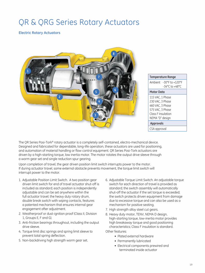
The QR Series Posi-Tork® rotary actuator is a completely self-contained, electro-mechanical device. Designed and fabricated for dependable, long-life operation, these actuators are used for positioning, and automation of material handling or flow control equipment. QR Series Posi-Tork actuators are driven by a high-starting torque, low inertia motor. The motor rotates the output drive sleeve through a worm gear set and single reduction spur gearing.
Upon completion of travel, the gear driven position limit switch interrupts power to the motor. If during actuator travel, some external obstacle prevents movement, the torque limit switch will interrupt power to the motor.
1. Adjustable Position Limit Switch. A two position gear driven limit switch for end of travel actuator shut-off is included as standard; each position is independently adjustable and can be set anywhere within the full actuator travel; the heavy duty rotary drum, double break switch with wiping contacts, features a patented mechanism that ensures internal gear engagement after adjustment.
2. Weatherproof or dust-ignition proof (Class II, Division 1, Groups E, F and G).
3. Anti-friction bearings throughout, including the output drive sleeve.
4. Torque limit disc springs and spring limit sleeve to prevent total spring deflection.
5. Non-backdriving high strength worm gear set.
6. Adjustable Torque Limit Switch. An adjustable torque switch for each direction of travel is provided as standard; the switch assembly will automatically shut-off the actuator if the set torque is exceeded; the switch protects driven equipment from damage due to excessive torque and can also be used as a mechanism for positive seating.
7. High strength alloy steel cut gears.8. Heavy duty motor, TENV, NEMA D design,
high-starting torque, low-inertia motor provides high breakaway torque and good positioning characteristics; Class F insulation is standard.
Other features: • Plated external hardware • Permanently lubricated • Electrical components prewired and
terminated inside actuator
Temperature Range
Ambient -30°F to +120°F
-34°C to +48°C
Motor Data
115 VAC, 1 Phase
230 VAC, 3 Phase
460 VAC, 3 Phase
575 VAC, 3 Phase
Class F Insulation
NEMA “D” design
Approvals
CSA approval
1
2
3
4
56
7
8

20
QR & QRG Series Rotary Actuators
The above formulas are intended as a guide. They neglect any effects of friction of bearings, belts, chains, or gears. For specific application assistance or for our application brochure, contact GE.
Force (lbs)
PinionRadius (ft)
Radius (ft)Diameter "2"
Diameter "1"
InputTorque (ft-lbs)
Torque(ft-lbs)
DrivenGear
DrivingGear
Weight(lbs)
OutputTorque(ft-lbs)
OutputTorque(ft-lbs)
InputTorque(ft-lbs)
InputTorque(ft-lbs)
LinearVelocity (In/Sec) =
Input Torque = Force x (Pinion Radius/0.9 Efficiency)
Torque (Running) = Radius x Weight
Force =
Input RPM
60Input Torque x (0.9 Efficiency)
Pinion Radius
( ) xxPinion Dia. x 3.14( ) Input
Torque OutputTorque
Dia."2"
Dia."1"( )
(Actuator selection must be basedon running torque for constant load applications)
=
xInputRPM
OutputRPM
Dia."1"
Dia."2"( )=
xInputTorque
OutputTorque
N.G.
N.P.( )=
N.G. = No. of Teeth on Driven Gear
N.P. = No. of Teeth on Driving Pinion
General Applications
Rack and Pinion Force — Torque Conversions
Force (lbs)
Approximately Torque Required (ft - lbs)
2.0 Inch DiameterPinion
2.5 Inch DiameterPinion
3.0 Inch DiameterPinion
3.5 Inch DiameterPinion
4.0 Inch DiameterPinion
4.5 Inch DiameterPinion
50 5 6 7 8 10 11
100 10 12 14 16 19 21
250 23 29 35 41 47 53
500 46 58 70 81 93 105
1000 93 116 140 162 186 209
1500 139 174 208 243 278 313
2000 185 232 278 325 371 417
2500 — 290 348 405 463 521
3000 — — 417 487 556 625
3500 — — — 568 649 730
4000 — — — — 741 834
4500 — — — — 834 —
Linear Speeds for Rack and Pinion Gates
Actuator Output RPM
Gate Velocity (inches/second)
2.0 Inch DiameterPinion
2.5 Inch DiameterPinion
3.0 Inch Diameter Pinion
3.5 Inch DiameterPinion
4.0 Inch DiameterPinion
4.5 Inch DiameterPinion
2.2 — — 0.35 0.40 0.46 0.52
3.4 — 0.45 0.53 0.62 0.71 0.80
4.8 0.50 0.63 0.76 0.88 1.01 1.13
6.5 0.68 0.85 1.02 1.19 1.36 1.53
10.5 — — — 1.92 2.20 2.47
11 1.15 1.44 1.73 2.02 2.30 2.59
17 1.78 2.23 2.67 3.12 3.56 4.00
18 — — — 3.30 3.77 4.24
24 2.51 3.14 3.77 4.40 5.03 5.66
34 3.56 4.45 5.34 6.23 — —
54 5.66 — — — — —
Above torques are calculated assuming a 10% friction loss between the rack and pinion.
21
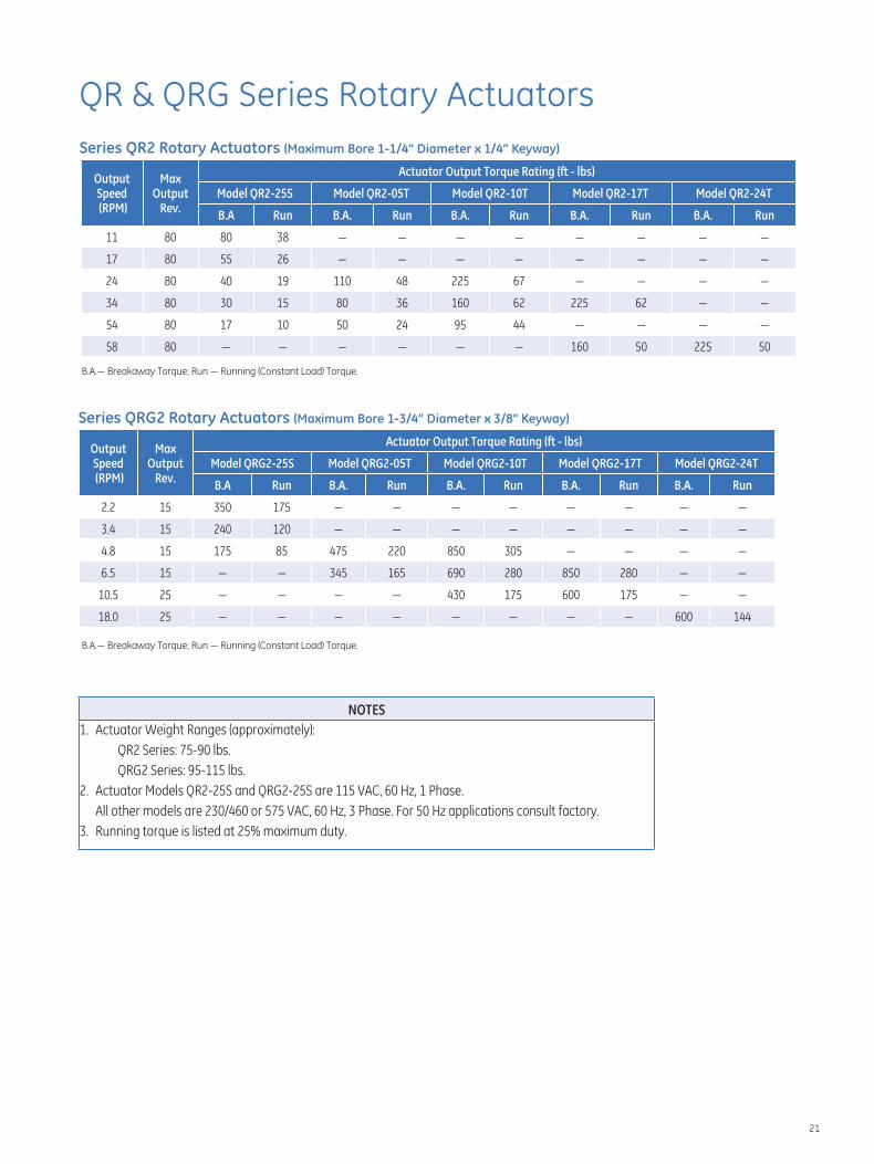
QR & QRG Series Rotary ActuatorsSeries QR2 Rotary Actuators (Maximum Bore 1-1/4” Diameter x 1/4” Keyway)
Output Speed (RPM)
Max Output
Rev.
Actuator Output Torque Rating (ft - lbs)
Model QR2-25S Model QR2-05T Model QR2-10T Model QR2-17T Model QR2-24T
B.A Run B.A. Run B.A. Run B.A. Run B.A. Run
11 80 80 38 — — — — — — — —
17 80 55 26 — — — — — — — —
24 80 40 19 110 48 225 67 — — — —
34 80 30 15 80 36 160 62 225 62 — —
54 80 17 10 50 24 95 44 — — — —
58 80 — — — — — — 160 50 225 50
B.A.— Breakaway Torque; Run — Running (Constant Load) Torque.
Series QRG2 Rotary Actuators (Maximum Bore 1-3/4” Diameter x 3/8” Keyway)
Output Speed (RPM)
Max Output
Rev.
Actuator Output Torque Rating (ft - lbs)
Model QRG2-25S Model QRG2-05T Model QRG2-10T Model QRG2-17T Model QRG2-24T
B.A Run B.A. Run B.A. Run B.A. Run B.A. Run
2.2 15 350 175 — — — — — — — —
3.4 15 240 120 — — — — — — — —
4.8 15 175 85 475 220 850 305 — — — —
6.5 15 — — 345 165 690 280 850 280 — —
10.5 25 — — — — 430 175 600 175 — —
18.0 25 — — — — — — — — 600 144
B.A.— Breakaway Torque; Run — Running (Constant Load) Torque.
NOTES
1. Actuator Weight Ranges (approximately):
QR2 Series: 75-90 lbs.
QRG2 Series: 95-115 lbs.
2. Actuator Models QR2-25S and QRG2-25S are 115 VAC, 60 Hz, 1 Phase.
All other models are 230/460 or 575 VAC, 60 Hz, 3 Phase. For 50 Hz applications consult factory.
3. Running torque is listed at 25% maximum duty.

22
QR & QRG Series Rotary ActuatorsQR2 Series Standard with Optional Handwheel
Model No. “A” “B” “D”
QR2-25S 11.06 6.00 3.50
QR2-05T 10.06 6.00 3.50
Model No. “A” “B” “D”
QR2-10T 11.06 6.00 3.50
QR2-17T 12.70 6.86 3.50
QR2-24T 13.63 6.86 3.50
NOTES
Dimensions are for reference only.
Contact GE for engineering drawings.

23
QR & QRG Series Rotary ActuatorsQRG2 Series Standard with Optional Handwheel
Model No. “A” “B”
QRG2-25S 11.06 6.00
QRG2-05T 10.06 6.00
Model No. “A” “B”
QRG2-10T 11.06 6.00
QRG2-17T 12.70 6.86
QRG2-24T 13.63 6.86
NOTES
Dimensions are for reference only.
Contact GE for engineering
drawings.

24
Standard Options
Clevis MountA cast iron clevis mount is standard on Eagle and 7100 Series actuators. The optional bracket will allow the actuator to pivot or can be used as a support on rigid mount applications.
Adjustable Trunnion Mount andTrunnion Mounting Brackets Adjustable, high strength, malleable cast iron trunnion mount with alloy steel, heat treated pins, is supplied as standard equipment on all 7200, 7300 and 74-7300 Series actuators. Adjustable trunnion mounting is optional on the Eagle, and 7100 Series actuators. The 7400 and 7500 Series actuators are supplied with alloy steel, heat treated and fixed location trunnion mount. Heavy duty cast and machine trunnion mounting brackets are available as an option on all 7000 Series actuators.
Adjustable Face/Flange Mount An adjustable, high strength, malleable iron face/flange mount is available as an option on the Eagle Series, 7100, 7200, 7300, 74-7300, and 7400 Series actuators where rigid mounting is required.
Manual Override A handwheel assembly with declutching mechanism is available for manual operation of the 7000, 8000 Series and QR and QRG Series Rotary actuators. Whenever the handwheel is operated, a mechanical override is used to disengage the motor. The actuator can then be positioned manually without risk of injury in the event the motor resumes operation. The actuator will remain in manual operation until the motor is re-energized. A handwheel is not available on ball screw actuators. Manual override without declutching mechanism is available on the Eagle Series.
25
Standard Options
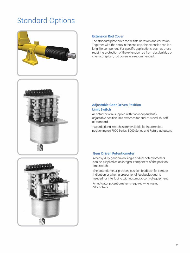
Extension Rod Cover The standard plate drive rod resists abrasion and corrosion. Together with the seals in the end cap, the extension rod is a long-life component. For specific applications, such as those requiring protection of the extension rod from dust buildup or chemical splash, rod covers are recommended.
Adjustable Gear Driven Position Limit Switch All actuators are supplied with two independently adjustable position limit switches for end-of-travel shutoff as standard.
Two additional switches are available for intermediate positioning on 7000 Series, 8000 Series and Rotary actuators.
Gear Driven Potentiometer A heavy duty gear driven single or dual potentiometers can be supplied as an integral component of the position limit switch.
The potentiometer provides position feedback for remote indication or when a proportional feedback signal is needed for interfacing with automatic control equipment.
An actuator potentiometer is required when using GE controls.

26
Standard Options
Electric Motor BrakeAn electric brake option is available for all sizes of Andco 7000, 8000 and QR actuators (standard on all ball screw actuators). The brake is recommended where high vibration is present or for accurate positioning applications when inertial coast is not permitted. The predictable coast of the actuator varies with velocity for each model and with the opposing load the actuator is moving. Consult factory for specific applications.
Single Phase Electronic (Dynamic) Motor BrakingAutomatically applies a D.C. motor voltage to the actuator motor upon shutoff of A.C. power. The brake is prewired and terminated in the actuator. Input voltage is 115 VAC, 60 Hz single phase. Not available on ball screw actuators.
Single Phase Solid State Reversing Starter/Programmable Controller InterfaceDirectly drives Andco 115 VAC, single phase motors. Accepts a contact closure as an input.
– Input power: 115 VAC, single phase
– Output power: 115 VAC, single phase (directional for reversing control)
– Contact closure switching characteristics: 15 VDC, 10ma.
Starter includes an electrical interlock. All starter components are prewired with connections terminated in the actuator. Single phase starter is also available with single phase electronic (dynamic) motor braking.
Three Phase Motor ControlAll 7000 Series three phase actuators can be furnished with an integral motor control that includes:
– Reversing contractor
– Thermal overload
– Control transformer with fuse
– Compartment space heater
– Prewired with all connecting points terminated

27
Standard Options
Model 4100 Position Indicating MeterA percent-of-full-travel meter is supplied with a trim potentiometer resistor, terminal block and connectors. A potentiometer is required in the actuator for feedback.
Three Phase Motor ControlAll 230 or 460 VAC, 60 Hz., 3 Phase actuators can be supplied with a factory wired, NEMA 4X, separately mounted motor control station.
Standard equipment includes: control transformer, control fuser, thermal overload relay, reversing contactor, multi-point terminal block sector switches and indication lights.
Positran™ TransmitterThis position transmitter outputs a 4-20mAdc signal proportional to actuator position. The signal can be used for the following functions:
■ Drive a position indicating meter ■ A feedback or control signal for other control devices
A potentiometer and compartment heater are required with the actuator.Positran is a trademark of Positran Manufacturing, Inc,

28
Position/Process Control
Remote Model 5100 Solid-state, closed-loop, panel-mount controller for use with single phase, motor-driven actuators. Automatically directs actuator movement in response to a signal generated by a command potentiometer mounted to the controller face (Figure 1) or a 4-20 mAdc, 10-50 mAdc or 1-5 VDC control signal (Figure 2).
The Andco Model 5100 control is a solid state servo device capable of driving a 10 Amp inductive load. It is designed for position or process control of an electric motor driven actuator.
A mode selection switch allows control with either the command potentiometer mounted on the controller face or a 4-20 mAdc (STD) 10-50 mAdc or a 1-5 VDC control signal. The selected mode signal is compared with the signal from the actuator feedback potentiometer. If an imbalance exists, the controller automatically directs actuator movement in the appropriate direction until the two signals match.
For positioning accuracy, an electronic braking circuit is provided. This circuit applies dynamic braking to the motor, stopping the motor rotor with 20 milliseconds.
Upon loss of the process command signal, the controller can control the actuator to stay in the last position, move to full open, move to full closed or switch to the command potentiometer position (specify).
For protection during system imbalance, the maximum number of motor starts is automatically limited to 25 per minute.
The output board is a separate plug-in module, electrically isolated from the main control board. An active filter is incorporated to reject electrical noise, normally eliminating the use of the shielded cable.
Standard equipment includes: ■ Position Indicator ■ Motion Indicator ■ Power On-Off Switch with Indicator ■ Auto/Manual Switch with Indicator ■ Command Potentiometer with 0-100% Dial ■ Panel Mount Enclosure
Feedback Potentiometer
115 VAC1 Phase
CommandPotentiometer0 to 100% Dial
FeedbackPotentiometerCurrent
Transducer
ControlProcessControl Signal
Fan MotorStarter Process
Setpoint
Supply Power
115 VAC1 Phase
Blending
Gate
0% 100%
(Percentage Open)
Figure 1
Figure 2

29
Position/Process ControlRemote Model 5100
Connection Diagram
Notes
Power, single phase115 VAC50/60 Hz
Manual Mode Input (command potentiometer)
0-1000 Ohms
Auto Mode Input (control signal)4-20 mAdc10-50 mAdcor 1-5 VDC
Feedback Input(actuator potentiometer)
0-1000 Ohms
Active Filter, 60 Hz Rejection -24 dB
Temperature Range0° to 150° F
0° to 65° C
Position Indicating Meter Range0-100 percent of full travel
Output (two triacs)10 Amp inductive load
Outline Drawing

30
Electric Actuator Smart Controller (EASC)
Models
SCC10-115/230 VAC115 or 230 Volt A.C. Actuators
SCC10-24 VAC24 Volt A.C. Actuators
Model
SCC10-24 VDC12 or 24 Volt D.C. Actuators
EASC (Micro-Processor Based Analog Controller) The Electric Actuator Smart Controller (EASC Model SCC-10) card provides accurate positioning control of electric motor actuators using an analog input signal. Setup and calibration is greatly simplified using microprocessor based technology. There are no dip switches to set or trim pots to adjust. Setup is quick and easy using the EASC menu viewed on an LED display. No external meters are required, even for potentiometer setup. Once the initial menu settings are chosen, the EASC performs a self-calibration routine, applying the menu selections to actual actuator performance. Calibration values are then stored in permanent non-volatile memory.
Features ■ Onboard LED display facilitates setup and calibration using the EASC Menu Setup.
■ Menu selection of input/output ranges including 4-20 mAdc, 1-5 VDC, 2-10 VDC and 0-10 VDC, or virtually any custom range required.
■ Automatic calibration; no resistors to add; no jumpers, trim pots or dip switches to adjust. Calibration is as simple as pressing a button.
■ Three relay outputs: fault, full closed and full open. (A.C. Models Only.)
■ Current sensing (over torque protection).— Optional on A.C. Models. Standard on D.C. Models.
■ Menu selectable fail options. ■ Intelligent positioning reduces motor cycling, increases motor life and extends the actuator duty.
■ Auto-jog feature. Constantly corrects and refines the positioning accuracy.
■ Quick disconnect terminal strips facilitate fast and easy actuator maintenance and troubleshooting.
■ Always wires the same; no need to determine rotation direction during installation; rotation is selected using the EASC Menu.
■ Robust power switching components, designed specifically for actuator motors, virtually eliminates field failures.
Model: SCC10

31
Electric Actuator Smart Controller (EASC)Model SCC10
Specifi cationsPower RequirementsModel SCC10-115/230A: 115 or 230 VAC, 1 Phase, 50/60 Hz. (Jumper selectable)
Model SCC-24 VAC: 24 VAC, 50/60 Hz.
Model SCC-24 VDC: 10-28 VDC
Input Command Signal Menu selectable factory defaults:
— 4 – 20 mADC— 1 – 5 VDC— 2 – 10 VDC— 0 – 10 VDCInfinite adjustment using EASC menu system
Signal Impedance Input: 250Ω current, 200KΩ voltageOutput: maximum load 500Ω current, minimum 500KΩ voltage
Dimensions 3-1/2 x 1-5/8 x 4 in.
Output Command Signal Menu selectable factory defaults:
— 4 – 20 mAdc— 1 – 5 VDC— 2 – 10 VDC— 0 – 10 VDC
Infinite adjustment using EASC menu system
Power Output Solid state, isolated from the input command and output position signals and rated at:
— 5 amps continuous at 115 VAC— 5 amps continuous at 230 VAC— 5 amps continuous at 24 VAC— 10 amps continuous at 24 VDC
All ratings assume the EASC is mounted on the actuator base plate.
Sensitivity Fully adjustable from 0.5% of total span, factory setto 1% of total span.
Dead Band Automatically set during calibration. Factory default at 1% of total span. Additional settings available using the EASC Menu System.
Zero Adjustment Automatically set during calibration.
Span Adjustment Automatically set during calibration.
Split Range Settable within the span range using at least 1.5VDC or 3mA of input.
Remote Control Optional Modus RTU control of all controller functions over a RS-485 multi-drop network
Ambient Temperature -40°F (with heater) to +150°F (-40°C to +65°C)
Action on Loss of Command Signal Factory default:
— Fail in last position (no movement)
Additional settings available through EASC menu:
— Fail open (maximum signal value)— Fail closed (minimum signal value)— Fail to a preset position
Relay Outputs - A.C. Models Only Three dry contacts outputs:
— Fault indicating loss of power, fuse failed, command signal loss or failure to move to position in preset time.
— End of travel open
— End of travel closed
— Contact Ratings: 1A @ 30VDC, 0.5A @ 135VAC resistive

32
Profibus DP is a registered trademark of the Profibus Trade Organization.
Profi bus® DP Controller
Model
DPC-10012 or 24 Volt D.C. Actuators
Model
DPC-120115 Volt A.C. Actuators
Features ■ Two wire control reduces installation and start up time compared to multi-cable wiring
■ Automatic calibration cuts down on start up time ■ No deadband eliminates need for field adjustment. ■ On line configuration of 36 operational parameters using generic Profibus software
■ Low power consumption; does not require ventilation ■ Electronic overload protection with built-in current monitoring ■ LED indicators for input, outputs and communication channel ■ Automatic calibration with local pushbutton or remote command ■ Dynamic breaking eliminates overshooting ■ Robust power switching components, designed specifically for actuator motors, virtually eliminates field failures
Specifi cationsPower SupplyDPC-100: 24/12 VDCDPC-120: 120 VAC
Communication Interface Profibus Standard
Protocol Profibus DP (Distributed Process)
Feedback Potentiometer 1000 Ohms/Optical Encoder
Position Input Accuracy 1.0% full scale standard, Maximum 0.1%
Temperature-40°F to +158°F ( -40°C to +70°C)
Relative Humidity 0 to 90% non-condensing
Dimensions DPC-100: 4.0 x 1.5 x 2.5 in.DPC-120: 4.25 x 1.75 x 3.75 in.
The DPC-100 & DPC-120 provide the following status and fault signals: Valve full closed
Valve full open
Percentage of open
Valve seeking position
Motor running
Valve closing
Valve opening
Motor thermostat tripped
Incomplete travel
Valve opening or closing manually
Valve jammed/current limiting
Motor still energized after stop or end of travel
Controller self-test (detects problems)
Communication failure
Average running current load
Peak running current load
Idle current load
Models DPC-100 and DPC-120
ApplicationProtocol: Profibus DP (Distributed Process)For on/off positioning control of motorized valve, it also serves as the vital intelligence link between PLC's in the control room and the actuators in the field. Up to 126 actuated valves can be controlled on a single network. The automatic calibra-tion feature requires no loop tuning. All operating parameters can be set from the communications center over the bus.

33
DeviceNet is a trademark of the Open DeviceNet Vendor Association.Allen Bradley is a trademark of Rockwell Automation, Inc.
DeviceNet™
Model
DNET115115 Volt A.C. Actuators
Application For on/off or positioning control of motorized valves. DeviceNet™ is a type of communication network that allows up to 63 field devices to be linked together with a single five-conductor cable. DeviceNet is a product of Allen-Bradley and is an open, non-proprietary, bus network. Typically, a DeviceNet system is used with the Allen-Bradley™ PLC5 and SLC series of programmable logic controllers. A standard DeviceNet Scanner interface is available for both types. Devices in the field are connected via a drop line to a 5 conductor trunk-line that is then routed to the scanner card.
Features ■ Provides open/stop/close or positioning control with limit switch status feedback
■ Provides instantaneous motor reversal protection ■ Command and end-of-travel verification alarm ■ Conforms to ODVA standards ■ Easy-to-see LED indicators for all control outputs, status inputs and diagnostic alarm
■ ESD functions for ‘go open’, ‘stay put’, or ‘go closed’
Specifi cationsHardware Specifications Supply Power: 2W @ 24VDCOperating Temperature: -4°F - 158°F (-20°C – 70°C)
Storage Temperature: -40°F - 176°F (-40°C – 80°C)Humidity: 90% Non CondensingSolid State Outputs: (2) Isolated 600VAC 15ADigital Inputs: (8) Dry ContactsAnalog Inputs: (2) Channels (see below)Processor: Temic 89C51CC01RAM: 1KFlash: 32KEEPROM: 32K
Serious Interfaces One CAN 2.0 port.
Network Communication Protocols Module Supports DeviceNet™ Group 2 Slave.
Analog Inputs Specification Resolution: 10bitAccuracy: 1% of FS.Linearity: 1% of FS.Temperature Drift: 2% of FS.Range: 0 to 5V or 0-20mA input for AI1 1-5K Potentiometer for the Position Feedback.
Technical Summary of DeviceNet™
Network Size: Up to 64 nodes (including scanner)
Network Length: Up to 1,640 ft. at 125 Kbps.
Data Packets: 0-8 bytes
Bus Topology: Trunkline/Dropline
Cable: 5-Conductor cable (2 for power, 2 for communication, and 1 for ground).
Thick Trunk Lines: Belden 3082A or 3083A
Thin Drop Lines: Belden 3084A or 3085A
Drop Lines: Max. drop length is 20 ft. with cumulative drop length of 512 ft.
Repeaters: Not currently, but expected in future revisions of specifications.
Input/Output Listing Digital Input Status: Bit 0 Communication LossBit 1 ReservedBit 2 Loss of Position SignalBit 3 Motor StallBit 4 Limit Calibration IncorrectBit 5 Thermostat TripBit 6 Manual OperationBit 7-15 Reserved
Digital Output Command:Bit 0 Open CommandBit 1 Close CommandBit 2 Stop CommandBit 3 ESD CommandBit 4-7 Future
Environmental Temperature Range: Storage: -40°F - 194°F(-40°C to +90°C)Operating: -4°f - 176°F (-20°C to +80°C)
Humidity Range: 5% to 95% at 77° F (25°C) non-condensing
Vibration: IEC 6B-2-6 1G @ 40-50 Hz., 0.012p-p @ 10-40 Hz.
Model DNET 115

34
ModBus® is a registered trademark of Gould Inc.
Modbus® Controller
Application The Modbus is an application specific controller, designed for positioning electric actuators using rotary feedback. Typical devices include rotary and linear actuators. Feedback may be via a potentiometer or a quadrature optical encoder. Controller outputs can drive small electric motors or motor starters directly.
A Modbus-485 communication network allows up to 100 devices on a single channel. The Modbus is powered by 24VDC and provides four supervisory inputs, configurable as limit switches or force open/close signals.
Automatic calibration is provided which requires no loop tuning. All operating parameters can be set as registers in the Modbus communications map.
Features ■ High resolution position input for up to 0.1% accuracy ■ 4-120/240VAC inputs for open and closed limit switches and 2 general purpose inputs
■ Simple 4-wire Modbus-485 communication network includes supervisory power
■ Robust communication, up to 500m cable length ■ Plugable terminal strips for easy field installation ■ Direct mounting within the actuator ■ Low power consumption; does not require ventilation ■ Electronic overload protection with built-in current monitoring optional
■ High power outputs can directly drive small motors ■ LED indicators on inputs, outputs and communication channel
■ Automatic calibration using local push button or remote command
■ Multi-vendor PLC support through the standard Modbus communication module
Typical Applications ■ Blending of bulk materials ■ Petroleum products and other liquids flow control ■ Level control for maintaining process supply
Specifi cations Actuator Voltage 120/240VAC 1Ø Current 4A (2 minute 25% duty-cycle) Fuse GMA 4 replaceable
Supervisory Voltage 10 to 25VDC Current 30mA @ 24VDC
Auxiliary Inputs Voltage 120/240VAC Current min 10mA / max 20mA
Communication Standard Modbus-RS485 differential Distance 500m (1,640ft.) Input Load 12K ohm, standard Termination 120Ω balanced line
Position Resolution 12 bit (1 part in 4096) Accuracy 0.1% full scale Potentiometer 1000Ω typical (500 to 10kΩ) Quadrature 1000 to 4096 pulses Optical Encoder
Environment Temperature -40°F to +158°F (-40°C to +70°C) Relative Humidity 0 to 95% non-condensing
Dimensions Length 96mm (3.75 in) Width 70mm (2.75 in) Height 36mm (1.40 in)


GEA19648 Andco ActuatorsRev 10.2012
GE Oil & Gas16240 Port Northwest DriveHouston, Texas 77041-2645 USAT: +1 832.590.2306 U.S. Toll Free T: 800.945.9898 F: +1 713.849.2879Email: [email protected]
Visit us online at: www.ge.com/energy
©2012, General Electric CompanyAll Rights Reserved* Trademark of General Electric Company