Embed Size (px)
Citation preview
NCHRP 12-70
Progress Review
Seismic Analysis and Design ofR t i i W ll Sl dRetaining Walls, Slopes and Embankments, and Buried
Structures
January 22, 2007

Obj ti f NCHRP 12 70 P j tObjectives of NCHRP 12-70 Project
Develop analytical methods and recommended LRFD specifications for seismic d i f t i i ll b i d t tdesign of retaining walls, buried structures, slopes, and embankmentsThe specifications “shall be compatible andThe specifications “shall be compatible and consistent with the philosophy and format of the AASHTO LRFD Bridge Designthe AASHTO LRFD Bridge Design Specifications”
Ref: NCHRP Research Project Statement f jProject 12-70, FY 2004
B k d NCHRP 12 70 P j tBackground – NCHRP 12-70 Project
Builds on other projects involving development of LRFD specifications
NCHRP 12-49 – completed in 2003NCHRP 20-07 – completed in 2006
S f NCHRP 12 49 & NCHRP 20 07Scope of NCHRP 12-49 & NCHRP 20-07 Limited to bridges and components directly attached (wing walls and abutments)attached (wing walls and abutments) Included determination of ground motionsExcluded retaining walls, buried structures, slopes, g pand embankments
N d f NCHRP 12 70 P j tNeed for NCHRP 12-70 ProjectDifficulties with retaining wall designsDifficulties with retaining wall designs
M-O method “blows up” with steep back slopes and high pga’sUncertainty in selecting seismic coefficientLimited guidance for some walls (e.g., soldier pile, tieback and soil nail walls)tieback, and soil nail walls)
Lack of written guidelines for slope stabilityAppropriate seismic coefficientAppropriate seismic coefficientAnalysis method (i.e., FS versus deformations)Liquefaction effectsLiquefaction effects
N d f NCHRP 12 70 P j t ( t )Need for NCHRP 12-70 Project (cont.)
Lack of methods in Section 12 of LRFD on seismic design of buried structures (i.e., d i l t d i b l tdrainage culverts and pipes, box culverts, pedestrian tunnels)
Transient versus permanent ground displacementTransient versus permanent ground displacementPermanent ground displacement (flotation, lateral spread, & settlement)p )Flexible versus rigid pipe
G l f P j tGoals for ProjectImprove existing methods or develop newImprove existing methods or develop new methods that overcome shortcomings
Optimize design approach for routine design and for special casesfor special casesAvoid hidden conservatismEnsure applicability to WUS and CEUSI l d “ i i d i ” i iInclude “no seismic design” provision
Be consistent with AASHTO LRFD Bridge Design Specificationsg p
Revisions to ground motions from NCHRP 20-07 ProjectOther changesOther changes

Status of ProjectStatus of ProjectWork completed (April 2004 – Dec. 2006)
Reviewed literature, identified issues & proposed methodologies
Prepared 1st Interim Report (Jan. 2005) p p ( )Prepared 2nd Interim Report (Mar. 2006)
Developed preliminary specifications, commentaries & example problems& example problems
Prepared 3rd Interim Report (Nov. 2006)
Work to complete (Jan. 2007 – July 2007)Prepare 2nd draft specifications, commentaries & example problems (May 2007)Finalize report, specifications and commentaries &Finalize report, specifications and commentaries & example problems (July 2007)
O i f P d A hOverview of Proposed ApproachGround motion recommendationsGround motion recommendations
Initial screeningAdjustments for wave scatteringDetermination of PGV from S1
Revised displacement charts/equationsG idance on soil p ope t selectionGuidance on soil property selection
Undrained strengthsImportance of c and ΦImportance of c and Φ
Design recommendationsMethod of analysis (simple & generalized)Design Checks (global, external & internal)
O i f P d A hOverview of Proposed ApproachDesign of retaining wallsDesign of retaining walls
Method of active pressure determinationDidn’t abandon M-O. Introduced (1) revised seismic coefficient for scattering, and (2) effects of cg, ( )Recommended generalized slope stability approach for many situations (layered soil profiles, geometric constraints, etc.)
Passive pressures from log spiral with cohesionPassive pressures from log spiral with cohesionSlopes & Embankments
Adjustments for wave scattering & displacementj g pBuried Structures
Procedures for treating transient ground displacementsdisplacements
S i i L d & L d F tSeismic Loads & Load Factors
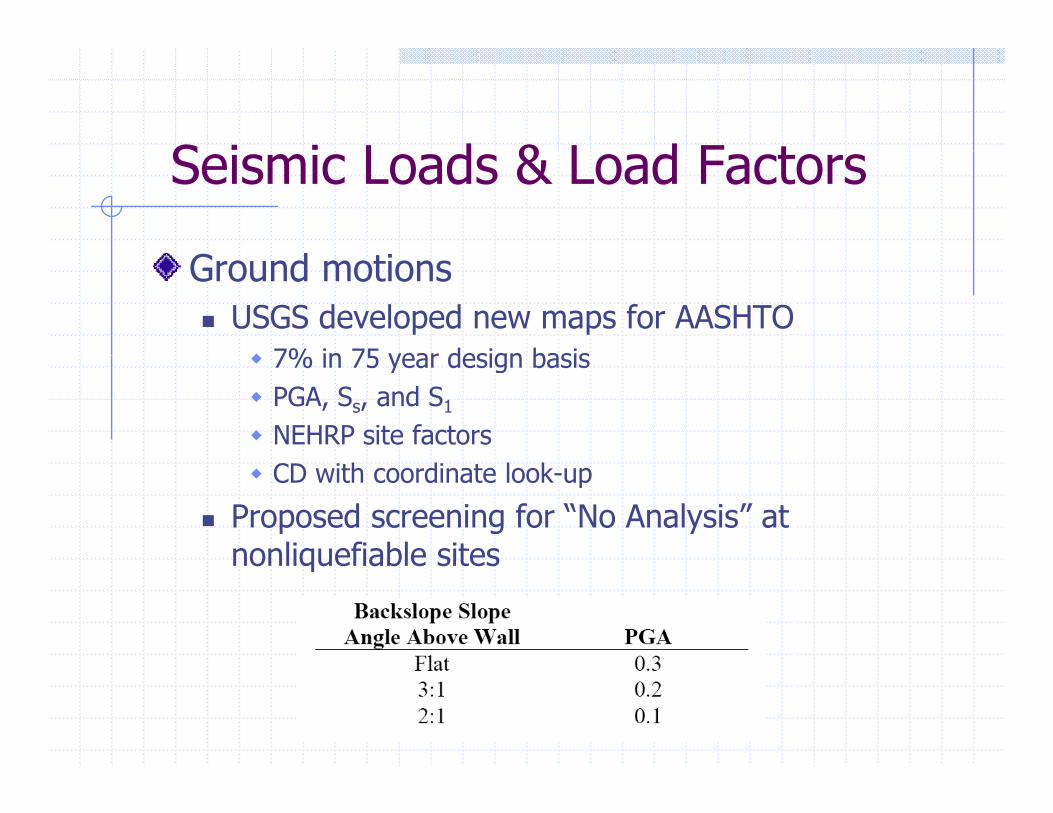
Ground motionsUSGS developed new maps for AASHTO
7% in 75 year design basis7% in 75 year design basisPGA, Ss, and S1
NEHRP site factorsCD with coordinate look-up
Proposed screening for “No Analysis” at nonliquefiable sitesnonliquefiable sites
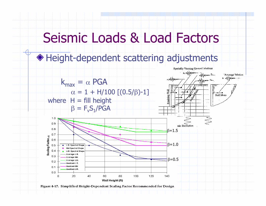
Seismic Loads & Load FactorsSeismic Loads & Load FactorsHeight-dependent scattering adjustments
kmax = α PGA1 H/100 [(0 5/β) 1]α = 1 + H/100 [(0.5/β)-1]
where H = fill heightβ = FvS1/PGA
β=1.5
β=1.0
β=0.5
Seismic Loads & Load FactorsSeismic Loads & Load Factors
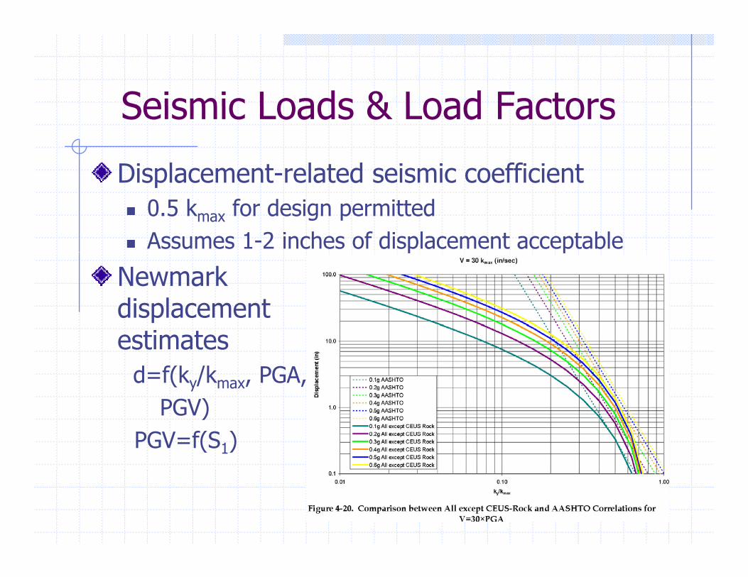
Displacement-related seismic coefficientDisplacement related seismic coefficient0.5 kmax for design permittedAssumes 1-2 inches of displacement acceptablep p
Newmark displacement estimates
d=f(ky/kmax, PGA, PGV)
PGV=f(S1)
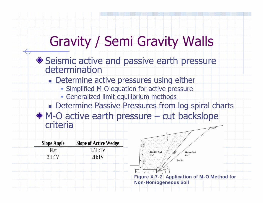
G it / S i G it W llGravity / Semi Gravity WallsSeismic active and passive earth pressureSeismic active and passive earth pressure determination
Determine active pressures using eitherSimplified M-O equation for active pressureSimplified M-O equation for active pressureGeneralized limit equilibrium methods
Determine Passive Pressures from log spiral chartsM O active earth pressure cut backslopeM-O active earth pressure – cut backslope criteria
Slope Angle Slope of Active Wedge Flat 1.5H:1V
3H:1V 2H:1V
Figure X.7-2 Application of M-O Method for Non-Homogeneous Soil
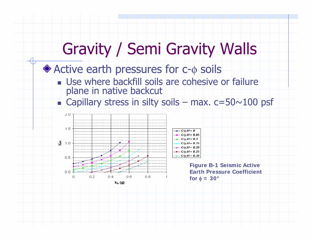
G it / S i G it W llGravity / Semi Gravity WallsActive earth pressures for c-φ soilsp φ
Use where backfill soils are cohesive or failure plane in native backcutCapillary stress in silty soils – max. c=50~100 psfCapillary stress in silty soils max. c 50 100 psf
Figure B-1 Seismic ActiveFigure B-1 Seismic Active Earth Pressure Coefficient for φ = 30°

Gravity / Semi Gravity WallsGravity / Semi Gravity Walls
Seismic passiveSeismic passive earth pressure for c-φ soils φ
Use log spiral methods rather than M O E tiM-O Equations Capillary stress in silty soils – max. Figure B-1 Seismic Activesilty soils max. c=50~100 psf
Fi B 3 S i i P i
Figure B-1 Seismic Active Earth Pressure Coefficient for φ = 30°
Figure B-3. Seismic Passive Earth Pressure Coefficient based on Log Spiral Procedure
G it / S i G it W llGravity / Semi Gravity WallsGeneralized equilibrium methodsGeneralized equilibrium methods
Use where M-O approach not suitable: soil conditions or backslope geometry/steep cut slopes Earth pressures applied as boundary force in commercially available slope stability programs
W ll di l t l iWall displacement analysisUse where
D/C Ratio > 1 (FS < 1)D/C Ratio > 1 (FS < 1)Allowable sliding displacements > 1 to 2 inches, supporting larger reductions in seismic coefficientpp g g
N G it C til W llNon-Gravity Cantilever WallsSeismic passive earth pressureSe s c pass e ea t p essu e
Limit equilibrium method (free- or fixed-earth pressure) for most analysesU l i l th d ith dj t t f ilUse log spiral method with adjustment for soil inertial effect
Wall displacement analysis / numericalWall displacement analysis / numerical methods
Beam column approachSoftware available (P-Y Wall, L-Pile, COM624, BMCOL)P-multiplier developed
FE or FD modeling allowedFE or FD modeling allowed
MSE W llMSE WallsGeneral
Initial static design meets AASHTO SpecificationsAdequate performance: Global/External/Internal StabilityStability
Method of AnalysisPerformance Criteria
No excessive sliding or rotation of structuralNo structural failure of reinforcing strips or facing elements
AnalysesEliminate Am = (1.45 –A) A factor (Segrestin and Bastick, 1988), )Displacement-based design (if necessary)
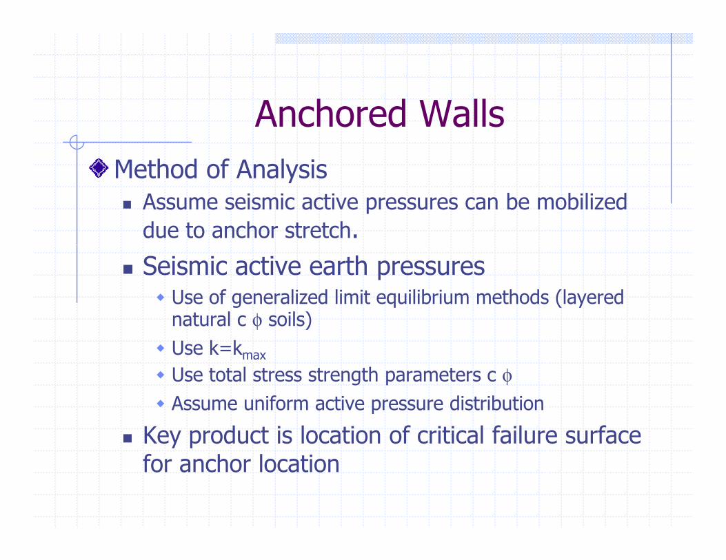
A h d W llAnchored WallsMethod of AnalysisMethod of Analysis
Assume seismic active pressures can be mobilized due to anchor stretch.Seismic active earth pressures
Use of generalized limit equilibrium methods (layered nat al c φ soils)natural c φ soils)Use k=kmax
Use total stress strength parameters c φAssume uniform active pressure distribution
Key product is location of critical failure surface f h l tifor anchor location
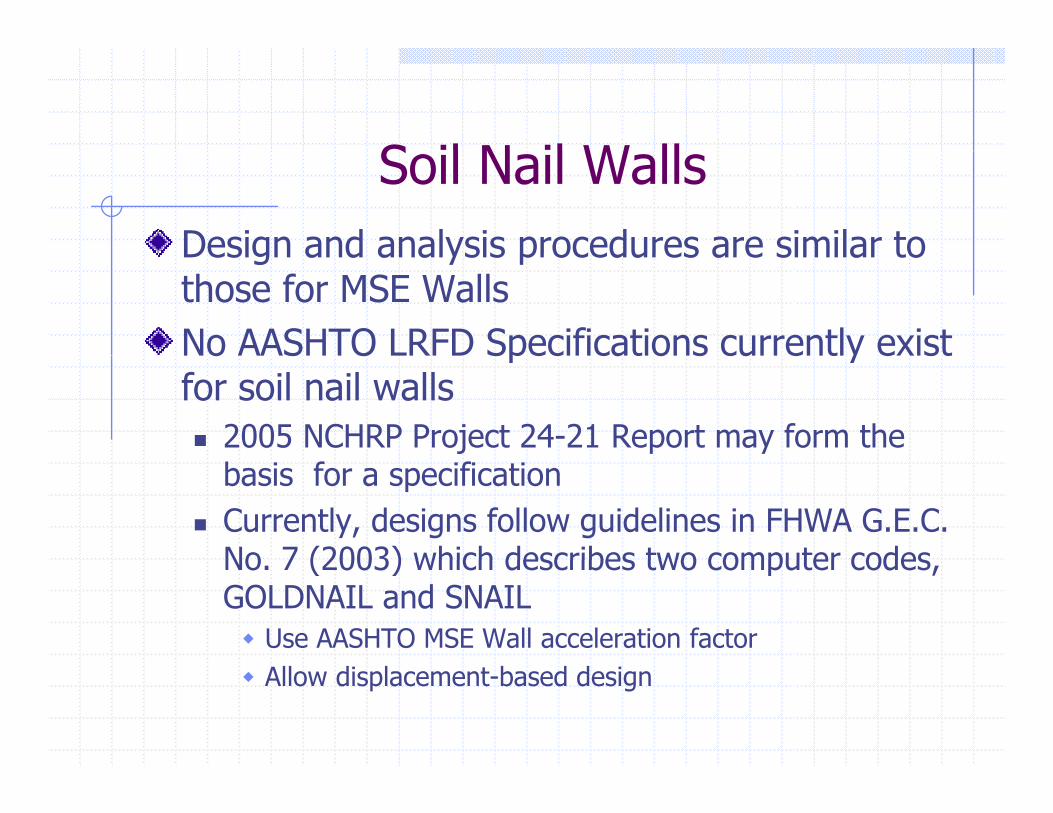
S il N il W llSoil Nail WallsDesign and analysis procedures are similar toDesign and analysis procedures are similar to those for MSE Walls No AASHTO LRFD Specifications currently existNo AASHTO LRFD Specifications currently exist for soil nail walls
2005 NCHRP Project 24-21 Report may form the basis for a specificationCurrently, designs follow guidelines in FHWA G.E.C. No 7 (2003) which describes two computer codesNo. 7 (2003) which describes two computer codes, GOLDNAIL and SNAIL
Use AASHTO MSE Wall acceleration factorAllow displacement-based design
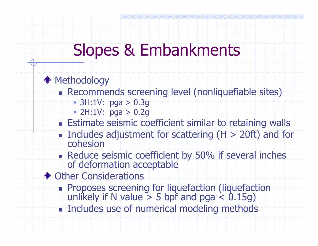
Sl & E b k tSlopes & Embankments
h d lMethodologyRecommends screening level (nonliquefiable sites)
3H:1V: pga > 0.3g2H:1V: pga > 0.2g
Estimate seismic coefficient similar to retaining wallsIncludes adjustment for scattering (H > 20ft) and for j g ( )cohesionReduce seismic coefficient by 50% if several inches of deformation acceptablep
Other ConsiderationsProposes screening for liquefaction (liquefaction unlikely if N value > 5 bpf and pga < 0.15g)y p pg g)Includes use of numerical modeling methods
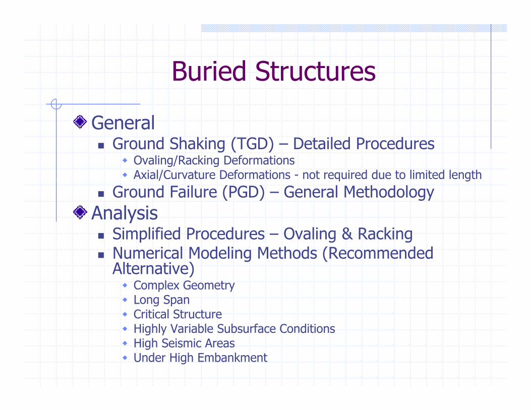
Buried StructuresBuried Structures
GeneralGeneralGround Shaking (TGD) – Detailed Procedures
Ovaling/Racking DeformationsAxial/Curvature Deformations - not required due to limited length/ q g
Ground Failure (PGD) – General Methodology Analysis
Simplified Procedures Ovaling & RackingSimplified Procedures – Ovaling & RackingNumerical Modeling Methods (Recommended Alternative)
Comple GeometComplex GeometryLong SpanCritical StructureHighly Variable Subsurface Conditionsg yHigh Seismic AreasUnder High Embankment
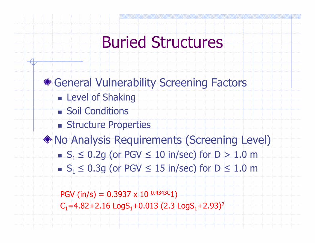
Buried StructuresBuried Structures
General Vulnerability Screening FactorsLevel of ShakingSoil ConditionsStructure Properties
N A l i R i t (S i L l)No Analysis Requirements (Screening Level) S1 ≤ 0.2g (or PGV ≤ 10 in/sec) for D > 1.0 mS ≤ 0 3g (or PGV ≤ 15 in/sec) for D ≤ 1 0 mS1 ≤ 0.3g (or PGV ≤ 15 in/sec) for D ≤ 1.0 m
PGV (in/s) = 0.3937 x 10 0.4343C1)( / ) )C1=4.82+2.16 LogS1+0.013 (2.3 LogS1+2.93)2