Embed Size (px)
Citation preview

ANDIAMO 2.XT (SRC)Hardware Guide
Version 2.1

page 2 of 56 ANDIAMO 2.XT (SRC) Hardware Guide - Version 2.1
Copyright
All rights reserved. Permission to reprint or electronically reproduce any document or graphic in whole or in part for any reason is expressly prohibited, unless prior written consent is obtained from the DirectOut GmbH.All trademarks and registered trademarks belong to their respective owners. It cannot be guaranteed that all product names, products, trademarks, requisitions, regulations, guidelines, specifications and norms are free from trade mark rights of third parties. All entries in this document have been thoroughly checked; however no guarantee for correctness can be given.DirectOut GmbH cannot be held responsible for any misleading or incorrect information provided throughout this manual. DirectOut GmbH reserves the right to change specifications at any time without notice.DirectOut Technologies® is a registered trademark of the DirectOut GmbH.
© DirectOut GmbH, 2016

page 3 of 56ANDIAMO 2.XT (SRC) Hardware Guide - Version 2.1
Table of contents
About This Document 5How to Use This Document .......................................................................... 5Conventions .................................................................................................. 5
CHAPTER 1: Overview 6Introduction ................................................................................................... 6Feature Summary .......................................................................................... 7Applications ................................................................................................... 7
CHAPTER 2: Legal issues & facts 8Before Installing This Device ......................................................................... 8Defective Parts/Modules ............................................................................. 8First Aid (in case of electric shock) ................................................................ 9Updates ....................................................................................................... 10Conditions of Warranty ............................................................................... 10Intended Operation .................................................................................... 10Conformity & Certificates ........................................................................... 11Contact ........................................................................................................ 11Contents ...................................................................................................... 12Accessories ................................................................................................. 13
CHAPTER 3: Installation 15Installing the Device .................................................................................... 15
CHAPTER 4: Operation 20Introduction ................................................................................................. 20Global Control .............................................................................................. 21Menu Control .............................................................................................. 22Clocking ....................................................................................................... 24Sample Rates .............................................................................................. 29Output Format ............................................................................................. 30Level Settings .............................................................................................. 31Level Meters - analog I/O ............................................................................ 32Level Meters - digital I/O .............................................................................33Signal Routing .............................................................................................34Connecting MADI ....................................................................................... 37Connecting Word clock ............................................................................... 38Connecting USB .......................................................................................... 38Connecting AES3 ........................................................................................ 39Connecting Analog ......................................................................................40
CHAPTER 5: Menu Navigation 42Signal Routing ............................................................................................. 42System Settings ..........................................................................................43
page 4 of 56 ANDIAMO 2.XT (SRC) Hardware Guide - Version 2.1
CHAPTER 6: Troubleshooting and Maintenance 45Troubleshooting ........................................................................................... 45Maintenance ................................................................................................ 45
CHAPTER 7: Technical Data 46
Appendix A - DSUB-25 Pin assignment 48
Index 50
page 5 of 56ANDIAMO 2.XT (SRC) Hardware Guide - Version 2.1
About This Document
About This Document
How to Use This DocumentThis document guides you through the installation and operation of the device. For information about the graphical user interface (GUI) please consult the offline help available from our website or use the online help within the gui.Use the Table of Contents at the beginning of the manual or Index Directory at the end of the document to locate help on a particular topic. You can access more information and latest news by visiting on the DirectOut website at www.directout.eu.
ConventionsThe following symbols are used to draw your attention to:
TIPS!indicate useful hints and shortcuts.
NOTES!are used for important points of clarification or cross references.
WARNINGS!alert you when an action should always be observed.
This document relates to:• ANDIAMO 2.XT - firmware version 6.1• ANDIAMO 2.XT SRC - firmware version 6.1
The front panel of the two versions differs and the related sections are marked accordingly.
page 6 of 56 ANDIAMO 2.XT (SRC) Hardware Guide - Version 2.1
CHAPTER 1: Overview
CHAPTER 1: Overview
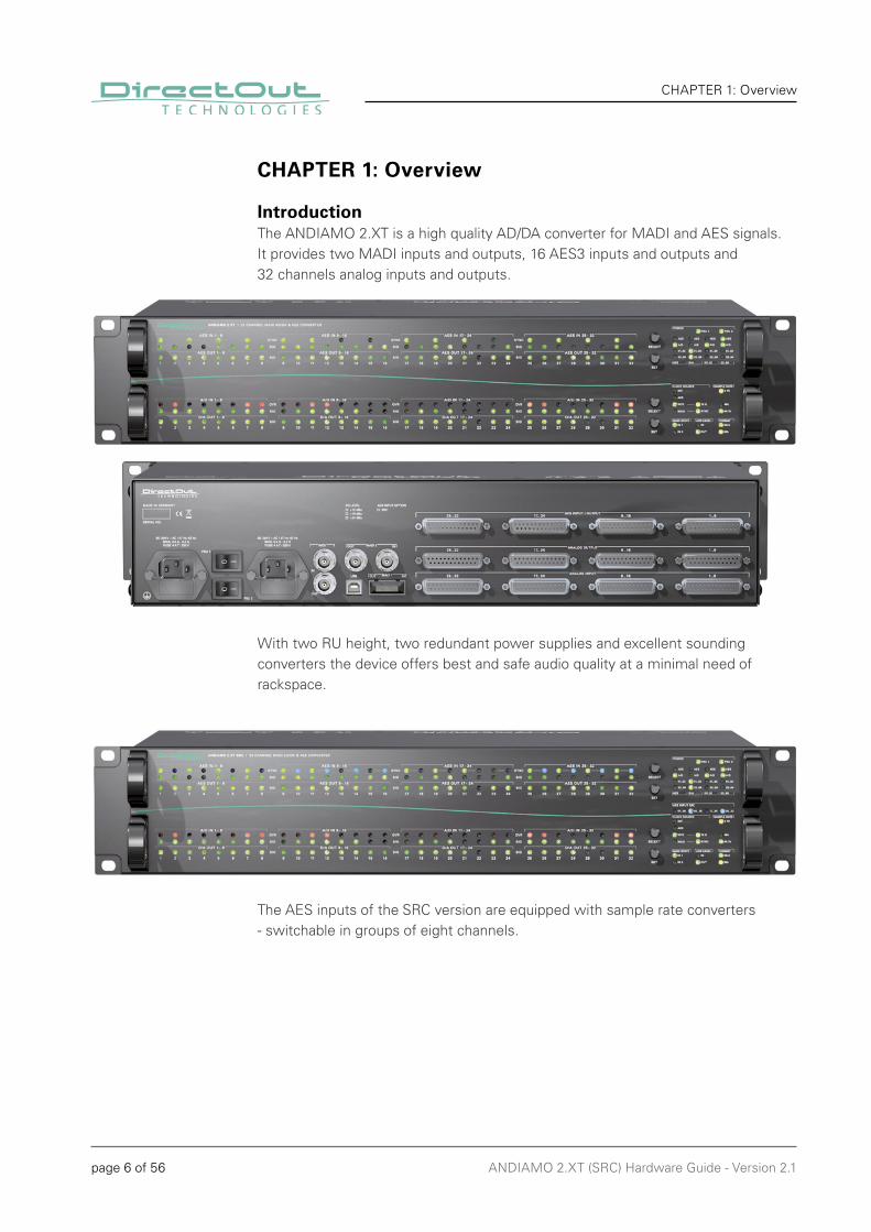
IntroductionThe ANDIAMO 2.XT is a high quality AD/DA converter for MADI and AES signals.It provides two MADI inputs and outputs, 16 AES3 inputs and outputs and 32 channels analog inputs and outputs.
With two RU height, two redundant power supplies and excellent sounding converters the device offers best and safe audio quality at a minimal need of rackspace.
The AES inputs of the SRC version are equipped with sample rate converters - switchable in groups of eight channels.
page 7 of 56ANDIAMO 2.XT (SRC) Hardware Guide - Version 2.1
CHAPTER 1: Overview
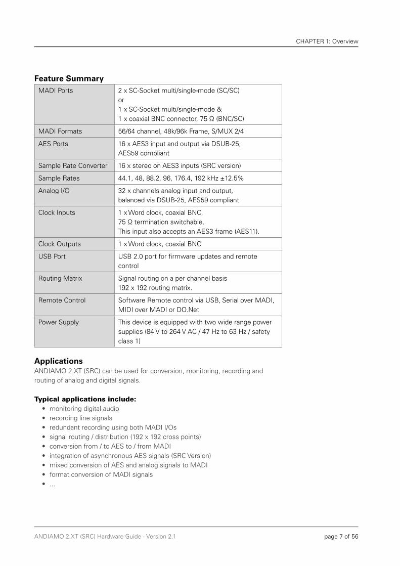
Feature SummaryMADI Ports 2 x SC-Socket multi/single-mode (SC/SC)
or1 x SC-Socket multi/single-mode &1 x coaxial BNC connector, 75 Ω (BNC/SC)
MADI Formats 56/64 channel, 48k/96k Frame, S/MUX 2/4
AES Ports 16 x AES3 input and output via DSUB-25, AES59 compliant
Sample Rate Converter 16 x stereo on AES3 inputs (SRC version)
Sample Rates 44.1, 48, 88.2, 96, 176.4, 192 kHz ±12.5%
Analog I/O 32 x channels analog input and output, balanced via DSUB-25, AES59 compliant
Clock Inputs 1 x Word clock, coaxial BNC, 75 Ω termination switchable, This input also accepts an AES3 frame (AES11).
Clock Outputs 1 x Word clock, coaxial BNC
USB Port USB 2.0 port for firmware updates and remote control
Routing Matrix Signal routing on a per channel basis192 x 192 routing matrix.
Remote Control Software Remote control via USB, Serial over MADI, MIDI over MADI or DO.Net
Power Supply This device is equipped with two wide range power supplies (84 V to 264 V AC / 47 Hz to 63 Hz / safety class 1)
ApplicationsANDIAMO 2.XT (SRC) can be used for conversion, monitoring, recording and routing of analog and digital signals.
Typical applications include:• monitoring digital audio• recording line signals• redundant recording using both MADI I/Os• signal routing / distribution (192 x 192 cross points)• conversion from / to AES to / from MADI• integration of asynchronous AES signals (SRC Version)• mixed conversion of AES and analog signals to MADI• format conversion of MADI signals• ...
page 8 of 56 ANDIAMO 2.XT (SRC) Hardware Guide - Version 2.1
CHAPTER 2: Legal issues & facts
CHAPTER 2: Legal issues & facts
Before Installing This Device
WARNING!
Please read and observe all of the following notes before installing this product:
• Check the hardware device for transport damage. • Any devices showing signs of mechanical damage or damage from the spillage of liquids must not be connected to the mains supply, or disconnected from the mains immediately by pulling out the power lead. • All devices must be grounded. The device is grounded through its IEC power connections. • All devices must be connected to the mains using the three-cord power leads supplied with the system. Only supply electrical interfaces with the voltages and signals described in these instructions.• Do not use the device at extreme temperatures. Proper operation can only be guaranteed between temperatures of 5º C and 45º C and a maximum relative humidity of 80 %, non-condensing. • The cabinet of the device will heat up. Do not place the device close to heating sources (e.g. heaters). Observe the environmental conditions.
Defective Parts/Modules
WARNING!
This device contains no user-serviceable parts. Therefore do not open the device. In the event of a hardware defect, please send the device to your DirectOut representative together with a detailed description of the fault. We would like to remind you to please check carefully whether the failure is caused by erroneous configuration, operation or connection before sending parts for repair.

page 9 of 56ANDIAMO 2.XT (SRC) Hardware Guide - Version 2.1
CHAPTER 2: Legal issues & facts
First Aid (in case of electric shock)
WARNING!
• Do not touch the person or his/her clothing before power is turned off, otherwise you risk sustaining an electric shock yourself. • Separate the person as quickly as possible from the electric power source as follows:
- Switch off the equipment. - Unplug or disconnect the mains cable.
• Move the person away from the power source by using dry insulating material (such as wood or plastic). • If the person is unconscious:
- Check their pulse and reanimate if their respiration is poor. - Lay the body down and turn it to one side. Call for a doctor immediately.
• Having sustained an electric shock, always consult a doctor.
page 10 of 56 ANDIAMO 2.XT (SRC) Hardware Guide - Version 2.1
CHAPTER 2: Legal issues & facts
UpdatesDirectOut products are continually in development, and therefore the information in this manual may be superseded by new releases. To access the latest documentation, please visit the DirectOut website: www.directout.eu.
WARNING!
No compensation can be claimed for damages caused by operation of this unit other than for the intended use described above. Consecutive damages are also excluded explicitly. The general terms and conditions of business of DirectOut GmbH are applied.
Conditions of WarrantyThis unit has been designed and examined carefully by the manufacturer and complies with actual norms and directives. Warranty is granted by DirectOut GmbH over the period of two years for all components that are essential for proper and intended operation of the device. The date of purchase is applied for this period. Consumable parts (e.g. battery) are excluded from warranty claims.
WARNING!
All claims of warranty will expire once the device has been opened or modified, or if instructions and warnings were ignored. For warranty claims please contact the dealer where your device was acquired.
This guide refers to firmware version 6.1
Intended Operation ANDIAMO 2.XT (SRC) is designed for conversion of audio signals from digital to digital, analog to digital and vice versa. In this context digital audio refers to a MADI signal (AES10) and AES signal (AES3).
page 11 of 56ANDIAMO 2.XT (SRC) Hardware Guide - Version 2.1
CHAPTER 2: Legal issues & facts
Conformity & Certificates
CE This device complies with the basic requests of applicable EU guidelines. The appropriate procedure for approval has been carried out.
RoHS (Restriction of the use of certain Hazardous Substances) This device was constructed fulfilling the directive on the restriction of the use of certain hazardous substances in electrical and electronic equipment 2002/95/EC.
WEEE (Directive on Waste Electrical and Electronic Equipment) Due to the directive 2002/96/EC for waste disposal this device must be recycled. For correct recycling please dispatch the device to: DirectOut GmbH, Leipziger Str. 3209648 Mittweida Germany Only stamped parcels will be accepted! WEEE-Reg.-No. DE 64879540
ContactDirectOut GmbH Leipziger Str. 32, 09648 Mittweida, Germany Phone: +49 (0)3727 5665-100 Fax: +49 (0)3727 5665-101Mail: [email protected]
page 12 of 56 ANDIAMO 2.XT (SRC) Hardware Guide - Version 2.1
CHAPTER 2: Legal issues & facts
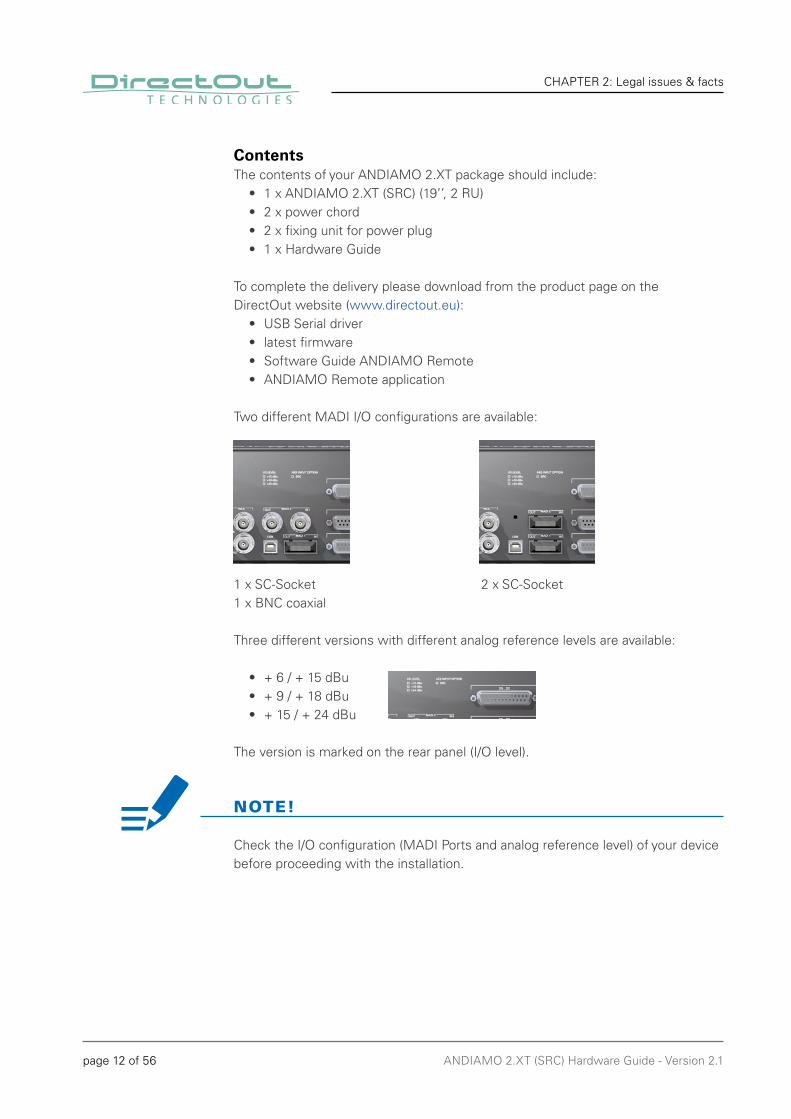
ContentsThe contents of your ANDIAMO 2.XT package should include:
• 1 x ANDIAMO 2.XT (SRC) (19’’, 2 RU) • 2 x power chord• 2 x fixing unit for power plug• 1 x Hardware Guide
To complete the delivery please download from the product page on theDirectOut website (www.directout.eu):
• USB Serial driver• latest fi rmware• Software Guide ANDIAMO Remote• ANDIAMO Remote application
Two different MADI I/O confi gurations are available:
1 x SC-Socket 2 x SC-Socket1 x BNC coaxial
Three different versions with different analog reference levels are available:
• + 6 / + 15 dBu • + 9 / + 18 dBu• + 15 / + 24 dBu
The version is marked on the rear panel (I/O level).
NOTE!
Check the I/O confi guration (MADI Ports and analog reference level) of your device before proceeding with the installation.
page 13 of 56ANDIAMO 2.XT (SRC) Hardware Guide - Version 2.1
CHAPTER 2: Legal issues & facts
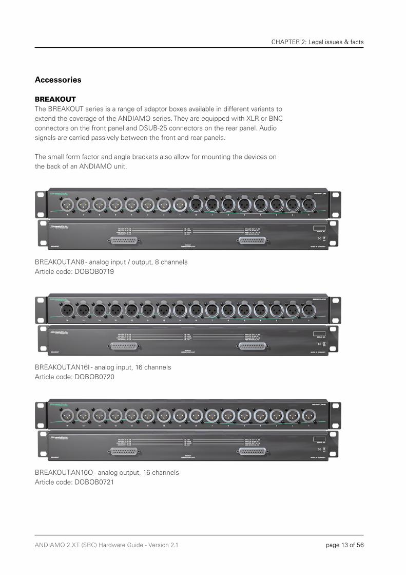
BREAKOUTThe BREAKOUT series is a range of adaptor boxes available in different variants to extend the coverage of the ANDIAMO series. They are equipped with XLR or BNC connectors on the front panel and DSUB-25 connectors on the rear panel. Audio signals are carried passively between the front and rear panels.
The small form factor and angle brackets also allow for mounting the devices on the back of an ANDIAMO unit.
BREAKOUT.AN8 - analog input / output, 8 channelsArticle code: DOBOB0719
BREAKOUT.AN16I - analog input, 16 channelsArticle code: DOBOB0720
BREAKOUT.AN16O - analog output, 16 channels Article code: DOBOB0721
Accessories
page 14 of 56 ANDIAMO 2.XT (SRC) Hardware Guide - Version 2.1
CHAPTER 2: Legal issues & facts
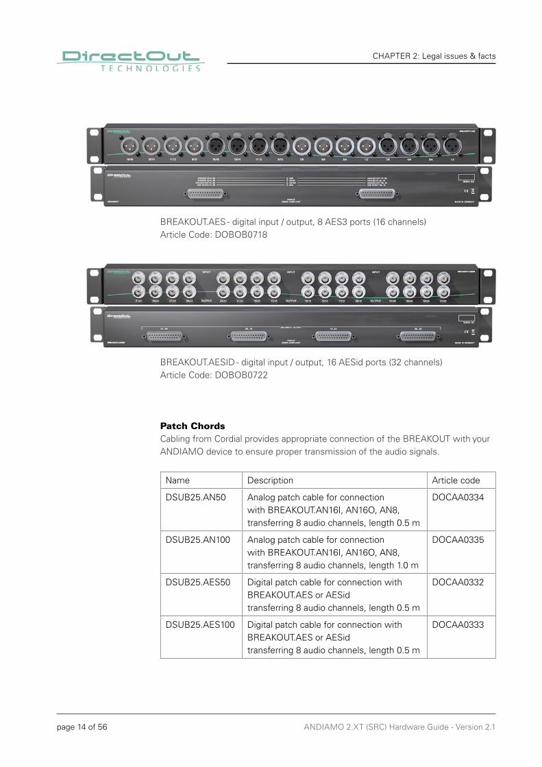
Patch ChordsCabling from Cordial provides appropriate connection of the BREAKOUT with your ANDIAMO device to ensure proper transmission of the audio signals.
Name Description Article code
DSUB25.AN50 Analog patch cable for connection with BREAKOUT.AN16I, AN16O, AN8, transferring 8 audio channels, length 0.5 m
DOCAA0334
DSUB25.AN100 Analog patch cable for connection with BREAKOUT.AN16I, AN16O, AN8, transferring 8 audio channels, length 1.0 m
DOCAA0335
DSUB25.AES50 Digital patch cable for connection with BREAKOUT.AES or AESid transferring 8 audio channels, length 0.5 m
DOCAA0332
DSUB25.AES100 Digital patch cable for connection with BREAKOUT.AES or AESid transferring 8 audio channels, length 0.5 m
DOCAA0333
BREAKOUT.AES - digital input / output, 8 AES3 ports (16 channels) Article Code: DOBOB0718
BREAKOUT.AESID - digital input / output, 16 AESid ports (32 channels)Article Code: DOBOB0722

page 15 of 56ANDIAMO 2.XT (SRC) Hardware Guide - Version 2.1
CHAPTER 3: Installation
Retain the protective cap if the optical port is unused. This will protect against soiling which can lead to malfunction.
Avoid damage from condensation by waiting for the device to adapt to the environmental temperature. Proper operation can only be guaranteed between temperatures of 5º C and 45º C and a maximum relative humidity of 80%, non-condensing. Ensure that the unit has suffi cient air circulation for cooling.
CHAPTER 3: Installation
Installing the Device1. Open the packaging and check that the contents have been delivered complete and undamaged. 2. Fix the device in a 19’’ frame with four screws, or place it on a non-slip horizontal surface.
WARNING!
Do not cover the fan outlets and the slots at the sides of the device!Do not block the fans by putting objects through the protective grid!
3. Remove the protective cap from the optical MADI port(s) before use.
BNC / SC Version SC / SC Version
NOTE!

page 16 of 56 ANDIAMO 2.XT (SRC) Hardware Guide - Version 2.1
CHAPTER 3: Installation
Do not connect voltage sources to the analog outputs. This may cause damage at the output stages.
This device may operate with only one power supply. To provide power supply redundancy, it is recommended to connect both PSU 1 and PSU 2 to independent power supplies with separate fuses.
This device must be connected to the mains using the three-cord power leads supplied with the system. Only supply the voltages and signals indicated (84 V – 264 V).
4. Connect the signal cables for the analog and digital audio signals to the DSUB-25 connectors.
WARNING
5. Using the power cord provided connect the PSU to a matching power supply:
WARNING
NOTE
page 17 of 56ANDIAMO 2.XT (SRC) Hardware Guide - Version 2.1
CHAPTER 3: Installation
To update the fi rmware an installed USB Serial driver (Windows) and the Update Tool are necessary. The software and the installation instructions are available at www.directout.eu.
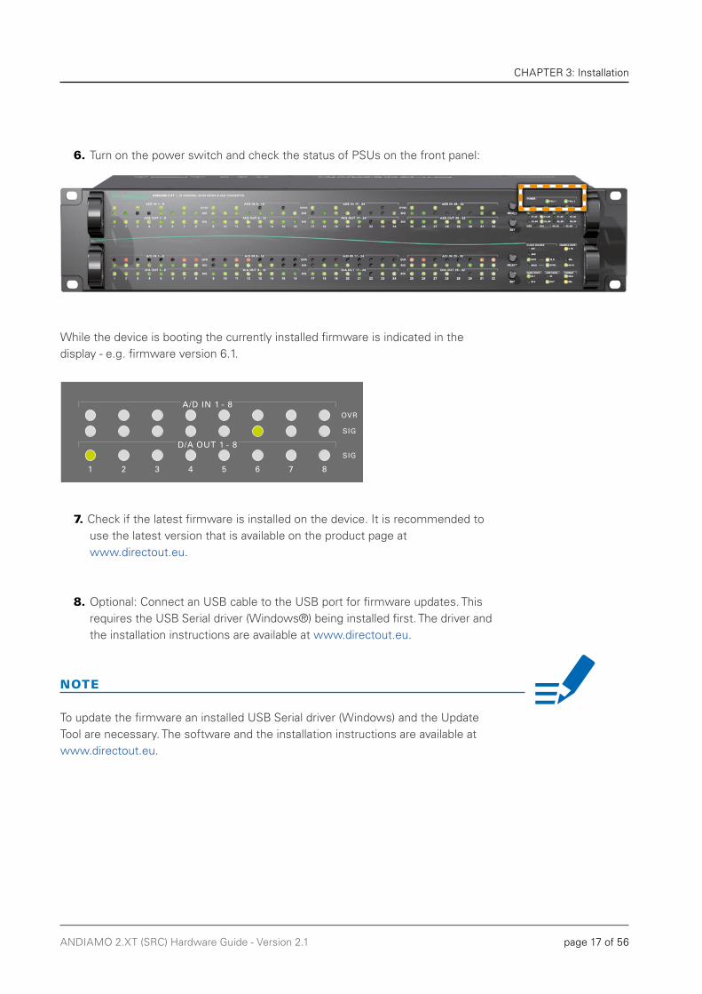
6. Turn on the power switch and check the status of PSUs on the front panel:
While the device is booting the currently installed fi rmware is indicated in the display - e.g. fi rmware version 6.1.
7. Check if the latest fi rmware is installed on the device. It is recommended to use the latest version that is available on the product page at www.directout.eu.
8. Optional: Connect an USB cable to the USB port for fi rmware updates. This requires the USB Serial driver (Windows®) being installed fi rst. The driver and the installation instructions are available at www.directout.eu.
NOTE
page 18 of 56 ANDIAMO 2.XT (SRC) Hardware Guide - Version 2.1
CHAPTER 3: Installation
Keep any packaging in order to protect the device should it need to be dispatched for service.
9. Installation of USB Serial driver
• download the USB Serial driver• download the ‘Installation Guide for USB Control• follow the installation instructions in the ‘Installation Guide for USB Control’
TIP
10. Installation of ‘ANDIAMO Remote’ (Windows® / OS X®)
• download the ‘Software Guide ANDIAMO Remote‘• download the ‘ANDIAMO Remote’ application • follow the installation instructions in the ‘Software Guide ANDIAMO Remote’

page 19 of 56ANDIAMO 2.XT (SRC) Hardware Guide - Version 2.1
CHAPTER 3: Installation
This page is left blank intentionally.
page 20 of 56 ANDIAMO 2.XT (SRC) Hardware Guide - Version 2.1
CHAPTER 4: Operation
IntroductionThis chapter describes the basic operation of the device. Note that throughout this manual, the abbreviation FS refers to sample rate or sample frequency. So, when dealing with scaling factors, the following sample rates can be written as:
• 44.1 kHz or 48 kHz = 1 FS• 88.2 kHz or 96 kHz = 2 FS• 176.4 kHz or 192 kHz = 4 FS
CHAPTER 4: Operation
page 21 of 56ANDIAMO 2.XT (SRC) Hardware Guide - Version 2.1
CHAPTER 4: Operation
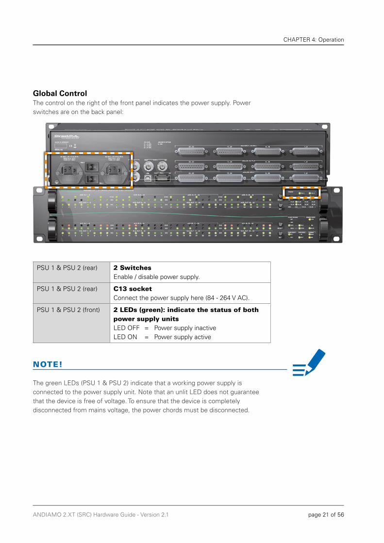
The green LEDs (PSU 1 & PSU 2) indicate that a working power supply is connected to the power supply unit. Note that an unlit LED does not guarantee that the device is free of voltage. To ensure that the device is completely disconnected from mains voltage, the power chords must be disconnected.
Global ControlThe control on the right of the front panel indicates the power supply. Power switches are on the back panel:
PSU 1 & PSU 2 (rear) 2 Switches Enable / disable power supply.
PSU 1 & PSU 2 (rear) C13 socketConnect the power supply here (84 - 264 V AC).
PSU 1 & PSU 2 (front) 2 LEDs (green): indicate the status of both power supply unitsLED OFF = Power supply inactiveLED ON = Power supply active
NOTE!
page 22 of 56 ANDIAMO 2.XT (SRC) Hardware Guide - Version 2.1
CHAPTER 4: Operation
Blinking LEDs are also used to indicate an error (e.g. missing sync). Concentrate on the section where one LED is blinking and the remaining LEDs are glowing weak.
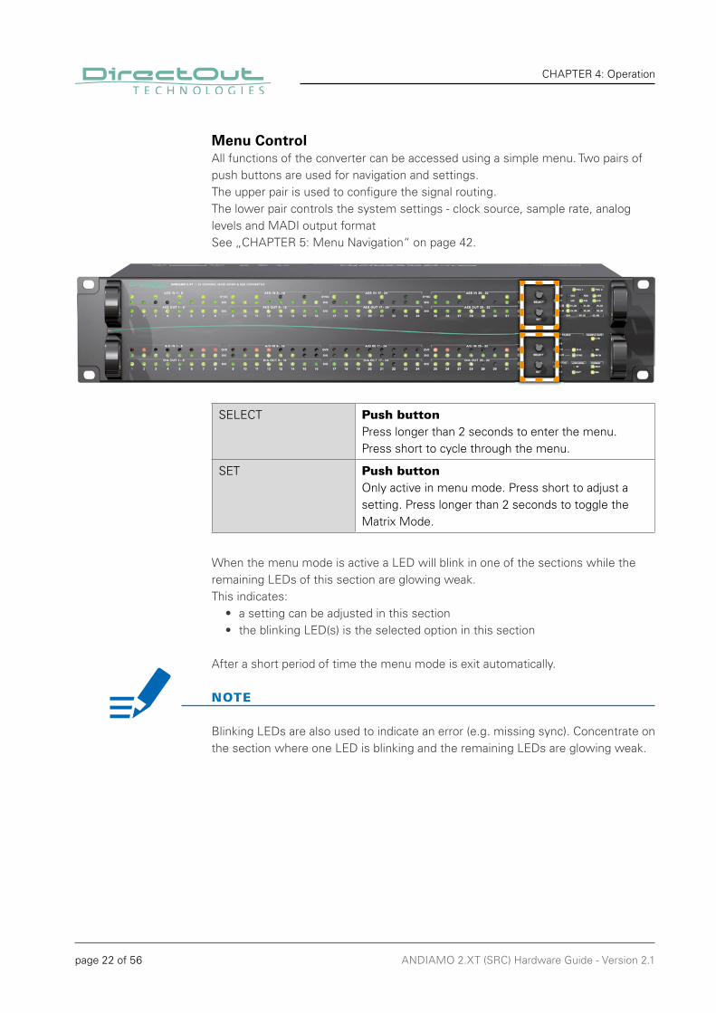
Menu ControlAll functions of the converter can be accessed using a simple menu. Two pairs of push buttons are used for navigation and settings.The upper pair is used to confi gure the signal routing.The lower pair controls the system settings - clock source, sample rate, analog levels and MADI output format See „CHAPTER 5: Menu Navigation“ on page 42.
SELECT Push buttonPress longer than 2 seconds to enter the menu. Press short to cycle through the menu.
SET Push buttonOnly active in menu mode. Press short to adjust a setting. Press longer than 2 seconds to toggle the Matrix Mode.
When the menu mode is active a LED will blink in one of the sections while the remaining LEDs of this section are glowing weak. This indicates:
• a setting can be adjusted in this section• the blinking LED(s) is the selected option in this section
After a short period of time the menu mode is exit automatically.
NOTE
page 23 of 56ANDIAMO 2.XT (SRC) Hardware Guide - Version 2.1
CHAPTER 4: Operation
The device settings can be adjusted either locally or via remote control.
ANDIAMO Remote offers access to additional settings:• Routing Matrix (Matrix Mode / Extended Routing)• Output gain/level trim for individual channels• AD/DA calibration in 0.1 dB increments• Configuration of the system fan control• Redundancy Modes• USB Embedder• Preset management• Display Dark
The settings are stored inside the device.

page 24 of 56 ANDIAMO 2.XT (SRC) Hardware Guide - Version 2.1
CHAPTER 4: Operation
ClockingSelectable clock sources are word clock, AES input MADI input or the internal clock. LEDs on the front panel inform about selection and sync state of the selected source. The current system clock is provided at the word clock output.The clock setting can be altered via remote control or locally - see „System Settings“ on page 43.
INT LED (green): indicates use of internal clock generator as clock source LED ON = Clock source set to internal clock generator
AES* LED (green): indicates use of AES as clock sourceLED ON = Clock source set to AES inputLED blinking = Clock source set to AES and no signal present (or all SRCs switched on).
WCK LED (green): indicates use of word clock as clock sourceLED ON = Clock source set to word clockLED blinking = Clock source set to word clock and no signal presentLED blinking pattern = signal locked but not in sync
75 Ω LED (yellow): indicates the termination status of word clock input.LED ON = Termination enabled LED OFF = Termination disabled
MADI LED (green): indicates use of MADI input as clock sourceLED ON = Clock source set to MADI inputLED blinking = Clock source set to MADI input and no signal present
SYNC** LED (green): indicates the lock/sync status of selected MADI inputLED ON = MADI input signal is in syncLED blinking = MADI input signal of is locked but not in sync
page 25 of 56ANDIAMO 2.XT (SRC) Hardware Guide - Version 2.1
CHAPTER 4: Operation
If the clock source is set to AES the selection of the AES port as clock source uses the following pattern in ascending order (port 1, port 2,...):lowest input port receiving a valid AES signal and SRC switched off
A SYNC LED indicates the sync state for each port individually.
Automatic AES port selection - a change of the AES input signal condition or changing the activation status of the SRCs may result in a different clock source.
* 16 SYNC LEDs in the metering section indicate the sync state of each AES port individually. Another 16 SRC LEDs indicate the activation status of the sample rate converters at each AES3 input port - see „Level Meters - digital I/O“ on page 33.
** The LED SYNC monitors the sync state of the selected MADI input - see „Clocking to MADI“ on page 28.
Clocking to AES
NOTE
page 26 of 56 ANDIAMO 2.XT (SRC) Hardware Guide - Version 2.1
CHAPTER 4: Operation
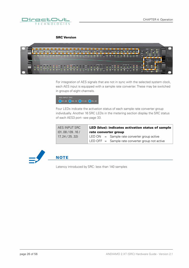
SRC Version
For integration of AES signals that are not in sync with the selected system clock, each AES input is equipped with a sample rate converter. These may be switched in groups of eight channels.
Four LEDs indicate the activation status of each sample rate converter group individually. Another 16 SRC LEDs in the metering section display the SRC status of each AES3 port - see page 33.
AES INPUT SRC(01..08 / 09..16 / 17..24 / 25..32)
LED (blue): indicates activation status of sample rate converter groupLED ON = Sample rate converter group active LED OFF = Sample rate converter group not active
NOTE
Latency introduced by SRC: less than 140 samples

page 27 of 56ANDIAMO 2.XT (SRC) Hardware Guide - Version 2.1
CHAPTER 4: Operation
This page is left blank intentionally.
page 28 of 56 ANDIAMO 2.XT (SRC) Hardware Guide - Version 2.1
CHAPTER 4: Operation
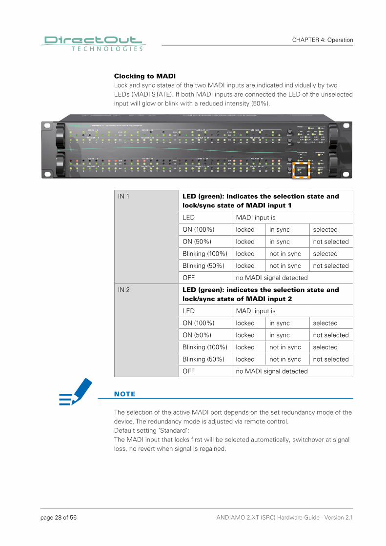
The selection of the active MADI port depends on the set redundancy mode of the device. The redundancy mode is adjusted via remote control.Default setting ‘Standard’:The MADI input that locks fi rst will be selected automatically, switchover at signal loss, no revert when signal is regained.
Clocking to MADILock and sync states of the two MADI inputs are indicated individually by two LEDs (MADI STATE). If both MADI inputs are connected the LED of the unselected input will glow or blink with a reduced intensity (50%).
IN 1 LED (green): indicates the selection state and lock/sync state of MADI input 1
LED MADI input is
ON (100%) locked in sync selected
ON (50%) locked in sync not selected
Blinking (100%) locked not in sync selected
Blinking (50%) locked not in sync not selected
OFF no MADI signal detected
IN 2 LED (green): indicates the selection state and lock/sync state of MADI input 2
LED MADI input is
ON (100%) locked in sync selected
ON (50%) locked in sync not selected
Blinking (100%) locked not in sync selected
Blinking (50%) locked not in sync not selected
OFF no MADI signal detected
NOTE
page 29 of 56ANDIAMO 2.XT (SRC) Hardware Guide - Version 2.1
CHAPTER 4: Operation
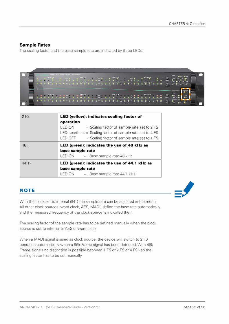
Sample RatesThe scaling factor and the base sample rate are indicated by three LEDs.
2 FS LED (yellow): indicates scaling factor of operationLED ON = Scaling factor of sample rate set to 2 FSLED heartbeat = Scaling factor of sample rate set to 4 FSLED OFF = Scaling factor of sample rate set to 1 FS
48k LED (green): indicates the use of 48 kHz as base sample rateLED ON = Base sample rate 48 kHz
44.1k LED (green): indicates the use of 44.1 kHz as base sample rateLED ON = Base sample rate 44.1 kHz
NOTE
With the clock set to internal (INT) the sample rate can be adjusted in the menu. All other clock sources (word clock, AES, MADI) defi ne the base rate automatically and the measured frequency of the clock source is indicated then.
The scaling factor of the sample rate has to be defi ned manually when the clock source is set to internal or AES or word clock.
When a MADI signal is used as clock source, the device will switch to 2 FS operation automatically when a 96k Frame signal has been detected. With 48k Frame signals no distinction is possible between 1 FS or 2 FS or 4 FS - so the scaling factor has to be set manually.

page 30 of 56 ANDIAMO 2.XT (SRC) Hardware Guide - Version 2.1
CHAPTER 4: Operation
Output FormatThe format of the MADI output signal can be defi ned - allowing for format conversion of the MADI signal. The output signal status is indicated by two LEDs (FORMAT).
56ch LED (green): indicates the channel format of the MADI output signal.LED ON = MADI output set to 56 channel mode.LED OFF = MADI output set to 64 channel mode.
96k LED (yellow): indicates the frame format of the MADI output signal @ 2 FS operation.LED ON = MADI output set to 96k FrameLED OFF = MADI output set to 48k Frame
NOTE
At 2 FS operation 56 ch refers to 28 channels (64ch > 32 channels).
At 4 FS operation 56 ch refers to 14 channels (64ch > 16 channels).
96k Frame is available at 2 FS operation only.
TIP
To convert a 2 FS MADI signal from 48k Frame (SMUX) into a 96k Frame signal, set the converter to 2 FS operation and activate 96k Frame.
page 31 of 56ANDIAMO 2.XT (SRC) Hardware Guide - Version 2.1
CHAPTER 4: Operation
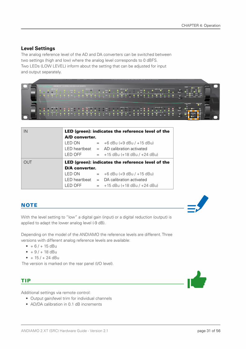
Level SettingsThe analog reference level of the AD and DA converters can be switched between two settings (high and low) where the analog level corresponds to 0 dBFS.Two LEDs (LOW LEVEL) inform about the setting that can be adjusted for input and output separately.
IN LED (green): indicates the reference level of the A/D converter.LED ON = +6 dBu (+9 dBu / +15 dBu)LED heartbeat = AD calibration activatedLED OFF = +15 dBu (+18 dBu / +24 dBu)
OUT LED (green): indicates the reference level of the D/A converter.LED ON = +6 dBu (+9 dBu / +15 dBu)LED heartbeat = DA calibration activatedLED OFF = +15 dBu (+18 dBu / +24 dBu)
NOTE
With the level setting to “low” a digital gain (input) or a digital reduction (output) is applied to adapt the lower analog level (-9 dB).
Depending on the model of the ANDIAMO the reference levels are different. Three versions with different analog reference levels are available:
• + 6 / + 15 dBu • + 9 / + 18 dBu• + 15 / + 24 dBu
The version is marked on the rear panel (I/O level).
TIP
Additional settings via remote control:• Output gain/level trim for individual channels• AD/DA calibration in 0.1 dB increments
page 32 of 56 ANDIAMO 2.XT (SRC) Hardware Guide - Version 2.1
CHAPTER 4: Operation
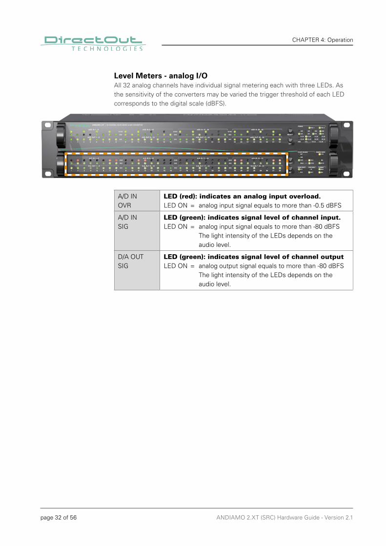
Level Meters - analog I/OAll 32 analog channels have individual signal metering each with three LEDs. As the sensitivity of the converters may be varied the trigger threshold of each LED corresponds to the digital scale (dBFS).
A/D INOVR
LED (red): indicates an analog input overload.LED ON = analog input signal equals to more than -0.5 dBFS
A/D INSIG
LED (green): indicates signal level of channel input.LED ON = analog input signal equals to more than -80 dBFS The light intensity of the LEDs depends on the audio level.
D/A OUTSIG
LED (green): indicates signal level of channel outputLED ON = analog output signal equals to more than -80 dBFS The light intensity of the LEDs depends on the audio level.
page 33 of 56ANDIAMO 2.XT (SRC) Hardware Guide - Version 2.1
CHAPTER 4: Operation
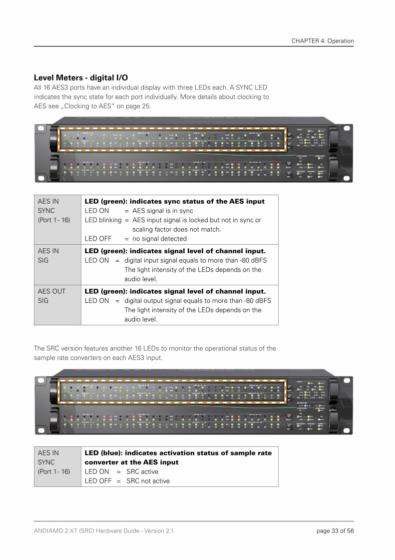
Level Meters - digital I/OAll 16 AES3 ports have an individual display with three LEDs each. A SYNC LED indicates the sync state for each port individually. More details about clocking to AES see „Clocking to AES“ on page 25.
AES INSYNC (Port 1 - 16)
LED (green): indicates sync status of the AES inputLED ON = AES signal is in syncLED blinking = AES input signal is locked but not in sync or scaling factor does not match.LED OFF = no signal detected
AES INSIG
LED (green): indicates signal level of channel input.LED ON = digital input signal equals to more than -80 dBFS The light intensity of the LEDs depends on the audio level.
AES OUTSIG
LED (green): indicates signal level of channel input.LED ON = digital output signal equals to more than -80 dBFS The light intensity of the LEDs depends on the audio level.
The SRC version features another 16 LEDs to monitor the operational status of the sample rate converters on each AES3 input.
AES INSYNC (Port 1 - 16)
LED (blue): indicates activation status of sample rate converter at the AES inputLED ON = SRC activeLED OFF = SRC not active

page 34 of 56 ANDIAMO 2.XT (SRC) Hardware Guide - Version 2.1
CHAPTER 4: Operation
Signal RoutingTwo methods of signal routing are available:
• ‘Standard Bank Routing’ - signal routing of analog and digital I/Os as a whole.• ‘Matrix Mode’ - individual signal routing of all analog and digital I/Os on a per channel basis.
Standard Bank RoutingA 4 by 4 routing matrix allows to distribute the signals among one another. There are four output destinations:
AES 16 AES3 output ports
D/A 32 analog outputs
01..32 MADI output channel 01 to 32
33..64 MADI output channel 33 to 64
The sources are selectable for each destination individually. The source selection is displayed by four green LEDs each of.
LED Code Source
AES input
Analog input
MADI input channel 01 to 32 (01 to 16 @ 2 FS, 01 to 08 @ 4 FS)
MADI input channel 33 to 64(17 to 32 @ 2 FS, 09 to 16 @ 4 FS)

page 35 of 56ANDIAMO 2.XT (SRC) Hardware Guide - Version 2.1
CHAPTER 4: Operation
MADI input @2 FS or @ 4 FS*Available for D/A and AES output.
Fallback mode**:AES input locked > AES signal is sourceAES input not locked > analog signal is sourceAvailable for MADI output (01..32 / 33..64)
mute - no input source selected
* MADI @ 2 FS = 32 channels, MADI @ 4 FS = 16 channels both portions of the MADI stream are used for D/A and AES output** Fallback mode - see page 36.
Matrix ModeChannel based routing can be set up via remote control (ANDIAMO Remote). Each output can be assembled individually from any input sources.
A subset of the Matrix Mode is the Extended Routing feature. It is switchable and enables both MADI I/Os to be used independently to:
• make full use of all conversion channels at higher sample rates • double the range of available MADI input channels • create two individual MADI feeds
The settings of the routing matrix are stored inside the device.It is possible to toggle between Standard Bank Routing and Matrix Mode without using the remote control. See „CHAPTER 5: Menu Navigation“ on page 42
LED Code Mode
All 16 LEDs on.Matrix Mode activeExtended Routing not activeBoth MADI outputs work in parallel.
Two LED columns blinking alternately.Matrix Mode activeExtended Routing activeMADI outputs may transmit individual signals.
page 36 of 56 ANDIAMO 2.XT (SRC) Hardware Guide - Version 2.1
CHAPTER 4: Operation
Fallback modeThe fallback mode is available with Standard Bank routing and applies to the MADI outputs.It offers:
• mixed use of AES and analog inputs to convert to a MADI bank of 32 channels• redundancy to avoid unwanted silence in the MADI signal
The trigger condition for switch-over is the lock status of the specifi c AES3 input port:
• AES input locked > AES signal is used as source• AES input not locked > analog signal is used as source
The switch-over affects the single channel pair only. All other inputs remain unchanged as long as they receive a valid AES input signal.
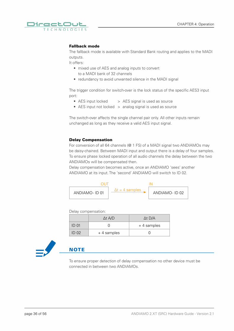
Delay CompensationFor conversion of all 64 channels (@ 1 FS) of a MADI signal two ANDIAMOs may be daisy-chained. Between MADI input and output there is a delay of four samples. To ensure phase locked operation of all audio channels the delay between the two ANDIAMOs will be compensated then.Delay compensation becomes active, once an ANDIAMO ‘sees’ another ANDIAMO at its input. The ‘second’ ANDIAMO will switch to ID 02.
Delay compensation:
Δt A/D Δt D/A
ID 01 0 + 4 samples
ID 02 + 4 samples 0
NOTE
To ensure proper detection of delay compensation no other device must be connected in between two ANDIAMOs.
ANDIAMO - ID 01 ANDIAMO - ID 02
OUT INΔt = 4 samples

page 37 of 56ANDIAMO 2.XT (SRC) Hardware Guide - Version 2.1
CHAPTER 4: Operation
Connecting MADIThe MADI ports are used for transmission of 64 audio channels (AES10).Two different MADI I/O confi gurations are available:
1 x SC-Socket 2 x SC-Socket1 x BNC coaxial
MADI 1OUT
SC socket (optical)MADI output (64 ch), connect for MADI output signal here
MADI 1IN
SC socket (optical)MADI input (64 ch), connect MADI input signal here
MADI 2OUT
SC socket (optical) or BNC socket (coaxial), 75 ΩMADI output (64 ch), connect for MADI output signal here
MADI 2IN
SC socket (optical) or BNC socket (coaxial), 75 ΩMADI input (64 ch), connect MADI input signal here
For MADI input selection see „Clocking to MADI“ on page 28.The MADI outputs may work in parallel or idependent from each other - see “Extended Routing” on page 35.
TIP
Additional settings via remote control:• Routing Matrix (Matrix Mode / Extended Routing)• Redundancy Modes
page 38 of 56 ANDIAMO 2.XT (SRC) Hardware Guide - Version 2.1
CHAPTER 4: Operation
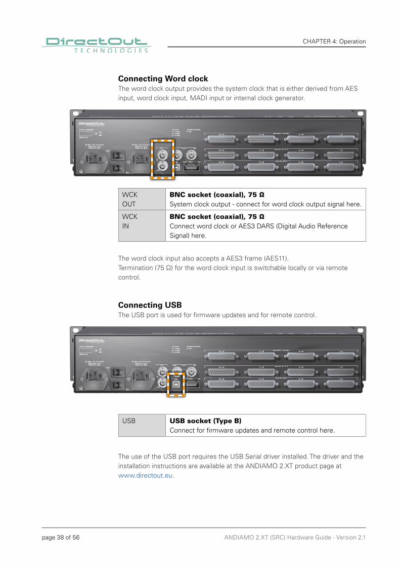
Connecting Word clockThe word clock output provides the system clock that is either derived from AES input, word clock input, MADI input or internal clock generator.
WCKOUT
BNC socket (coaxial), 75 ΩSystem clock output - connect for word clock output signal here.
WCKIN
BNC socket (coaxial), 75 ΩConnect word clock or AES3 DARS (Digital Audio Reference Signal) here.
The word clock input also accepts a AES3 frame (AES11).Termination (75 Ω) for the word clock input is switchable locally or via remote control.
Connecting USBThe USB port is used for fi rmware updates and for remote control.
USB USB socket (Type B)Connect for fi rmware updates and remote control here.
The use of the USB port requires the USB Serial driver installed. The driver and the installation instructions are available at the ANDIAMO 2.XT product page atwww.directout.eu.
page 39 of 56ANDIAMO 2.XT (SRC) Hardware Guide - Version 2.1
CHAPTER 4: Operation
The pinout of the digital and analog I/O is different. Check for appropriate cabling to ensure proper operation and to avoid damages caused by improper connections.
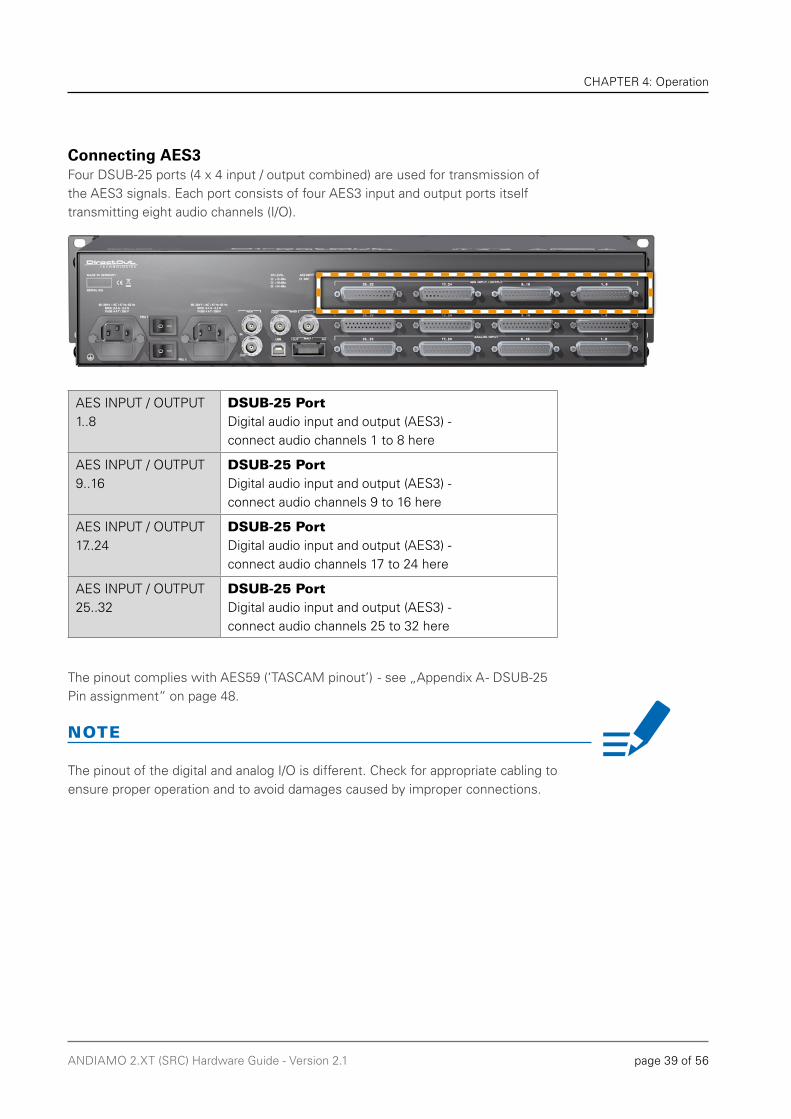
Connecting AES3Four DSUB-25 ports (4 x 4 input / output combined) are used for transmission of the AES3 signals. Each port consists of four AES3 input and output ports itself transmitting eight audio channels (I/O).
AES INPUT / OUTPUT1..8
DSUB-25 PortDigital audio input and output (AES3) - connect audio channels 1 to 8 here
AES INPUT / OUTPUT9..16
DSUB-25 PortDigital audio input and output (AES3) - connect audio channels 9 to 16 here
AES INPUT / OUTPUT17..24
DSUB-25 PortDigital audio input and output (AES3) - connect audio channels 17 to 24 here
AES INPUT / OUTPUT25..32
DSUB-25 PortDigital audio input and output (AES3) - connect audio channels 25 to 32 here
The pinout complies with AES59 (‘TASCAM pinout’) - see „Appendix A - DSUB-25 Pin assignment“ on page 48.
NOTE
page 40 of 56 ANDIAMO 2.XT (SRC) Hardware Guide - Version 2.1
CHAPTER 4: Operation
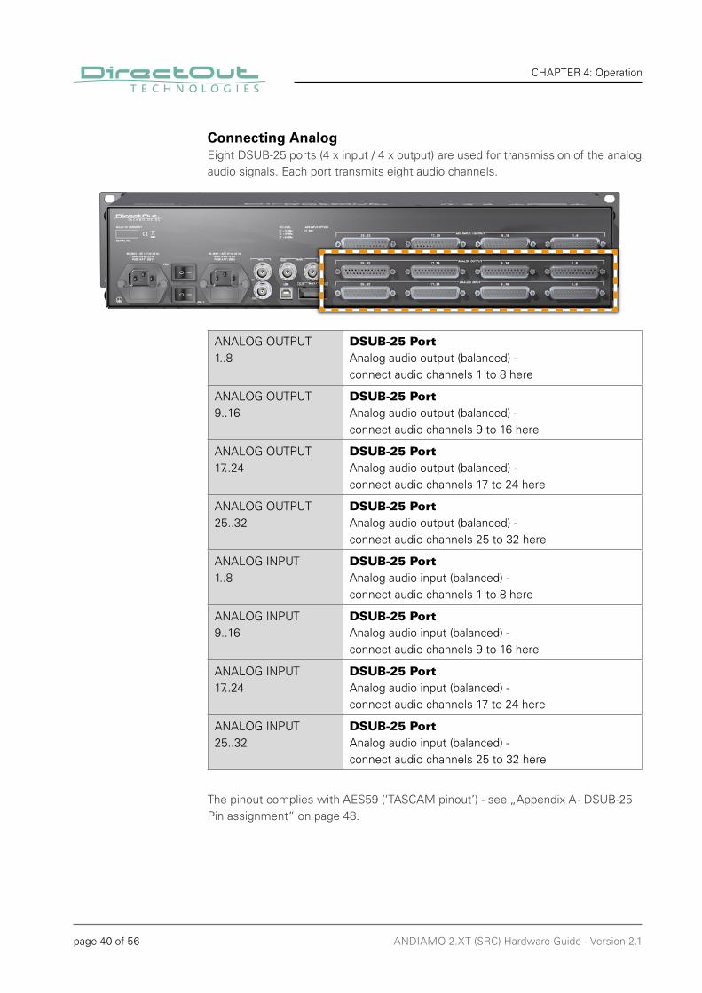
Connecting AnalogEight DSUB-25 ports (4 x input / 4 x output) are used for transmission of the analog audio signals. Each port transmits eight audio channels.
ANALOG OUTPUT1..8
DSUB-25 PortAnalog audio output (balanced) - connect audio channels 1 to 8 here
ANALOG OUTPUT9..16
DSUB-25 PortAnalog audio output (balanced) - connect audio channels 9 to 16 here
ANALOG OUTPUT17..24
DSUB-25 PortAnalog audio output (balanced) - connect audio channels 17 to 24 here
ANALOG OUTPUT25..32
DSUB-25 PortAnalog audio output (balanced) - connect audio channels 25 to 32 here
ANALOG INPUT1..8
DSUB-25 PortAnalog audio input (balanced) - connect audio channels 1 to 8 here
ANALOG INPUT9..16
DSUB-25 PortAnalog audio input (balanced) - connect audio channels 9 to 16 here
ANALOG INPUT17..24
DSUB-25 PortAnalog audio input (balanced) - connect audio channels 17 to 24 here
ANALOG INPUT25..32
DSUB-25 PortAnalog audio input (balanced) - connect audio channels 25 to 32 here
The pinout complies with AES59 (‘TASCAM pinout’) - see „Appendix A - DSUB-25 Pin assignment“ on page 48.
page 41 of 56ANDIAMO 2.XT (SRC) Hardware Guide - Version 2.1
CHAPTER 4: Operation
The pinout of the digital and analog I/O is different. Check for appropriate cabling to ensure proper operation and to avoid damages caused by improper connections.
Do not connect voltage sources to the analog outputs. This may cause damage at the output stages. Observe the technical specifications listed in this document.
The line output is not servo balanced. Do not connect the negative lead to ground. This may cause damage at the output stage. Observe the technical specifications listed in this document.
NOTE
WARNING
WARNING
page 42 of 56 ANDIAMO 2.XT (SRC) Hardware Guide - Version 2.1
CHAPTER 5: Menu Navigation
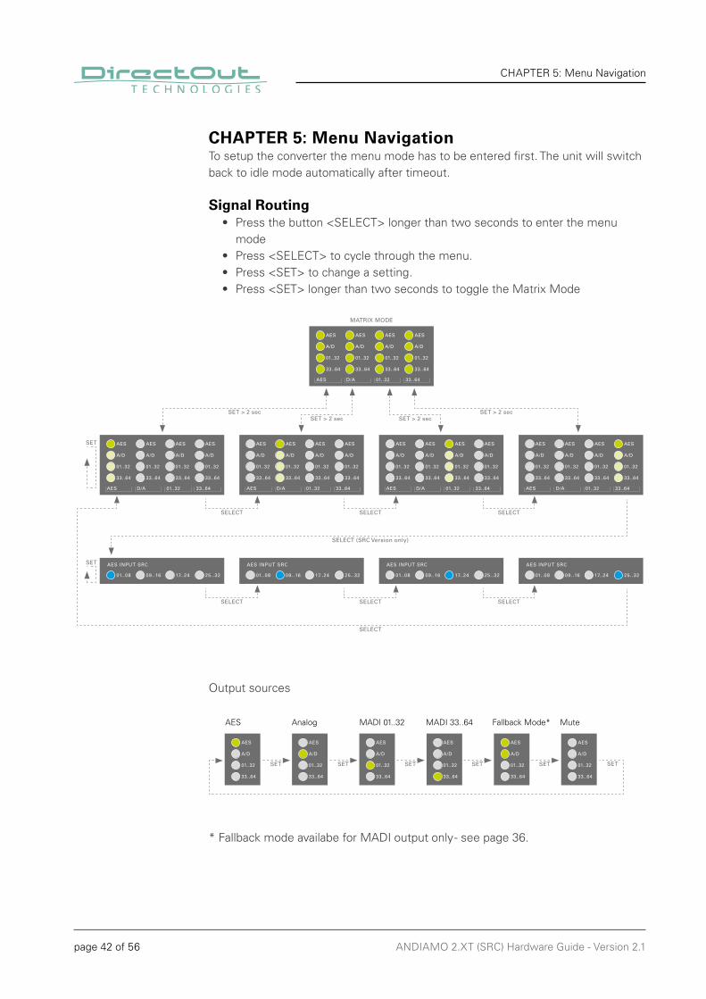
CHAPTER 5: Menu NavigationTo setup the converter the menu mode has to be entered first. The unit will switch back to idle mode automatically after timeout.
Signal Routing• Press the button <SELECT> longer than two seconds to enter the menu mode• Press <SELECT> to cycle through the menu.• Press <SET> to change a setting.• Press <SET> longer than two seconds to toggle the Matrix Mode
Output sources
AES Analog MADI 01..32 MADI 33..64 Fallback Mode* Mute
* Fallback mode availabe for MADI output only - see page 36.
SET > 2 secSET > 2 sec SET > 2 sec
SET > 2 sec
SELECT SELECT SELECT
SELECT SELECT SELECT
MATRIX MODE
SELECT (SRC Version only)
SELECT
SET
SET
SET SET SET SET SET SET
page 43 of 56ANDIAMO 2.XT (SRC) Hardware Guide - Version 2.1
CHAPTER 5: Menu Navigation
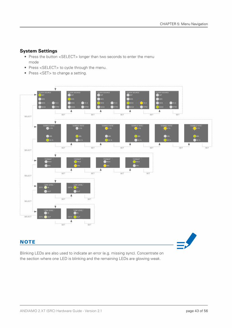
System Settings• Press the button <SELECT> longer than two seconds to enter the menu mode• Press <SELECT> to cycle through the menu.• Press <SET> to change a setting.
NOTE
SET SET SET SET SET
SET SET SET SET SET SET
SET SET SET SET
SET SET
50% 100%
SET SET
50% 100%
SELECT
SELECT
SELECT
SELECT
SELECT
Blinking LEDs are also used to indicate an error (e.g. missing sync). Concentrate on the section where one LED is blinking and the remaining LEDs are glowing weak.
page 44 of 56 ANDIAMO 2.XT (SRC) Hardware Guide - Version 2.1
CHAPTER 5: Menu Navigation
This page is left blank intentionally.
page 45 of 56ANDIAMO 2.XT (SRC) Hardware Guide - Version 2.1
CHAPTER 6: Troubleshooting and Maintenance
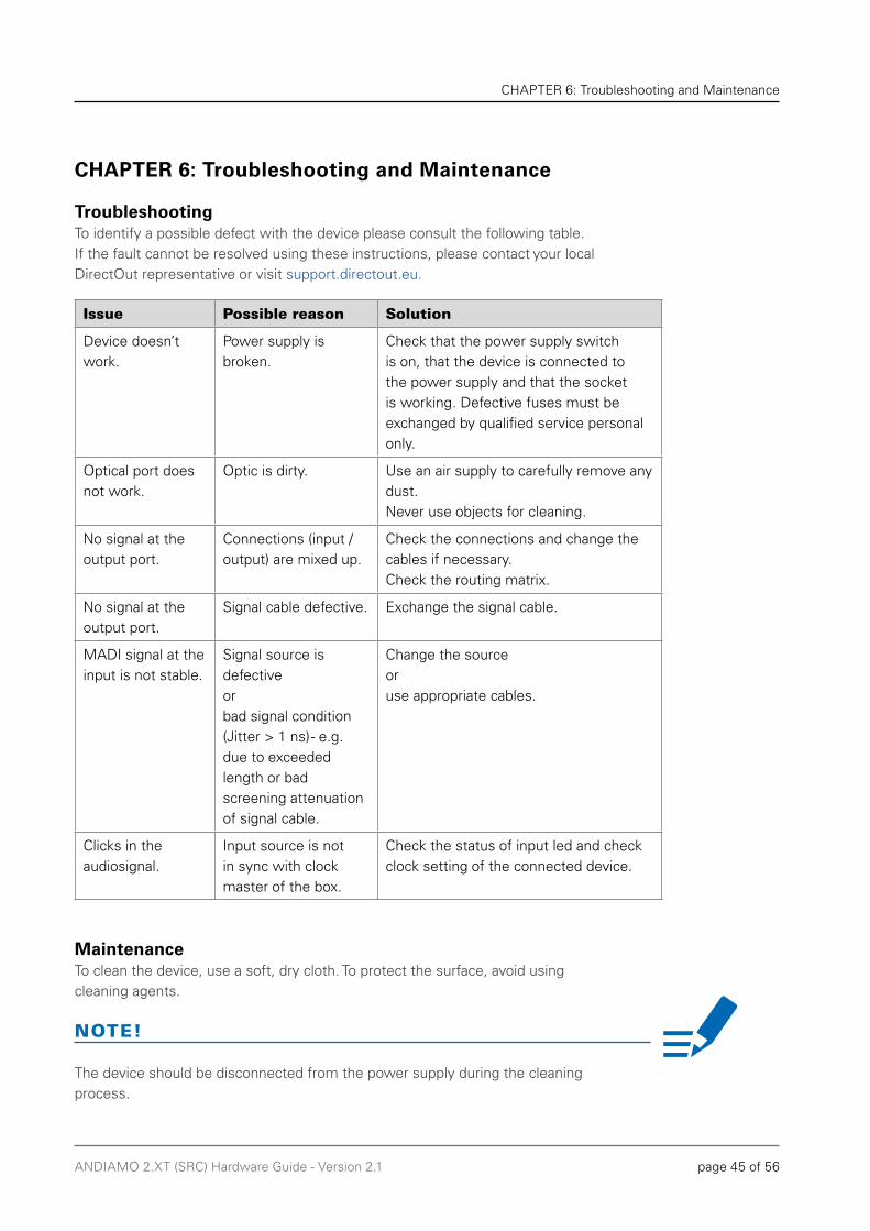
TroubleshootingTo identify a possible defect with the device please consult the following table. If the fault cannot be resolved using these instructions, please contact your local DirectOut representative or visit support.directout.eu.
MaintenanceTo clean the device, use a soft, dry cloth. To protect the surface, avoid using cleaning agents.
The device should be disconnected from the power supply during the cleaning process.
CHAPTER 6: Troubleshooting and Maintenance
Issue Possible reason Solution
Device doesn’t work.
Power supply is broken.
Check that the power supply switch is on, that the device is connected to the power supply and that the socket is working. Defective fuses must be exchanged by qualified service personal only.
Optical port does not work.
Optic is dirty. Use an air supply to carefully remove any dust. Never use objects for cleaning.
No signal at the output port.
Connections (input / output) are mixed up.
Check the connections and change the cables if necessary.Check the routing matrix.
No signal at the output port.
Signal cable defective. Exchange the signal cable.
MADI signal at the input is not stable.
Signal source is defective or bad signal condition (Jitter > 1 ns) - e.g. due to exceeded length or bad screening attenuation of signal cable.
Change the source or use appropriate cables.
Clicks in the audiosignal.
Input source is not in sync with clock master of the box.
Check the status of input led and check clock setting of the connected device.
NOTE!

page 46 of 56 ANDIAMO 2.XT (SRC) Hardware Guide - Version 2.1
CHAPTER 7: Technical Data
CHAPTER 7: Technical Data
Dimensions• Width 19’’ (483 mm)• Height 2 RU (89 mm)• Depth 10’’ (254 mm)
Weight• about 5.4 kg
Power Consumption• 40 W
Power Supply• 84 V - 264 V AC / 47 Hz - 63 Hz / Safety class 1
Fuses• Fuse 250 V - 2 A (slow-blow) – 2 fuses per power supply
Environmental Conditions• Operating temperature +5°C up to +45°C • Relative humidity: 10% - 80%, non condensing
MADI Port - (Version BNC/SC)• 2 x BNC socket (1 x input / 1 x output) • Impedance: 75 Ω • 0.3 V up to 0.6 V (peak to peak)
MADI Port - (Version BNC/SC or SC/SC)• 1 x or 2 x SC socket FDDI (input / output)• ISO/IEC 9314-3• Wave length: 1310 nm• Multi mode 62.5/125 µm or 50/125 µm• optional: single mode 9/125 µm
AES3 Port (I/O)• 4 x DSUB-25 (16 x AES3 input / output each), AES59 compliant• AES3 balanced, 110 Ω
Analog Input• 4 x DSUB-25 (8 analog audio channels each - balanced), AES59 compliant
Analog Output• 4 x DSUB-25 (8 analog audio channels each - balanced), AES59 compliant• The outputs are not servo balanced.

page 47 of 56ANDIAMO 2.XT (SRC) Hardware Guide - Version 2.1
CHAPTER 7: Technical Data
A/D Section• SNR: -115.5 dB RMS (20 Hz - 20 kHz) / -118 dB(A)• THD @ -1 dBFS: -113 dB• Frequency response: -0.15 dB (10 Hz) / -0.15 dB (20 kHz)• Input impedance: 20 kΩ (balanced) / 10 kΩ (unbalanced)• Input level (depending on model):
Model / Level High Low Model A +15 dBu +6 dBu Model B +18 dBu +9 dBu Model C +24 dBu +15 dBu
D/A Section• SNR: -116 dB RMS (20 Hz - 20 kHz) / -119 dB(A)• THD @ -1 dBFS: -109 dB• Frequency response: -0,5 dB (10 Hz) / -0,15 dB (20 kHz)• Output impedance: < 50 Ω• Output level (depending on model):
Model / Level High Low Minimum Load Resistance Model A +15 dBu +6 dBu 600 Ω Model B +18 dBu +9 dBu 600 Ω Model C +24 dBu +15 dBu 2.4 kΩ
Sample Rate• 44.1 / 48 / 88.2 / 96 / 176.4 / 192 kHz ± 12.5 %
MADI Format (I/O)• 48k Frame, 96k Frame• 56 channel, 64 channel• S/MUX 2/4
SRC Performance [SRC Version]• all rates from 30 kHz to 50 kHz and their multiples• THD+N: 140 dB• Frequency response ripple: < 0.025 dB• Latency: < 140 samples
Latency• about 1 ms (AD - DA)
Word Clock• 1 x BNC socket (75 Ω impedance) - input• 1 x BNC socket (75 Ω impedance) - output• Termination 75 Ω switchable• AES11 (DARS supported)
USB• 1 x USB 2.0 socket (Type B)
page 48 of 56 ANDIAMO 2.XT (SRC) Hardware Guide - Version 2.1
Appendix A - DSUB-25 Pin assignment
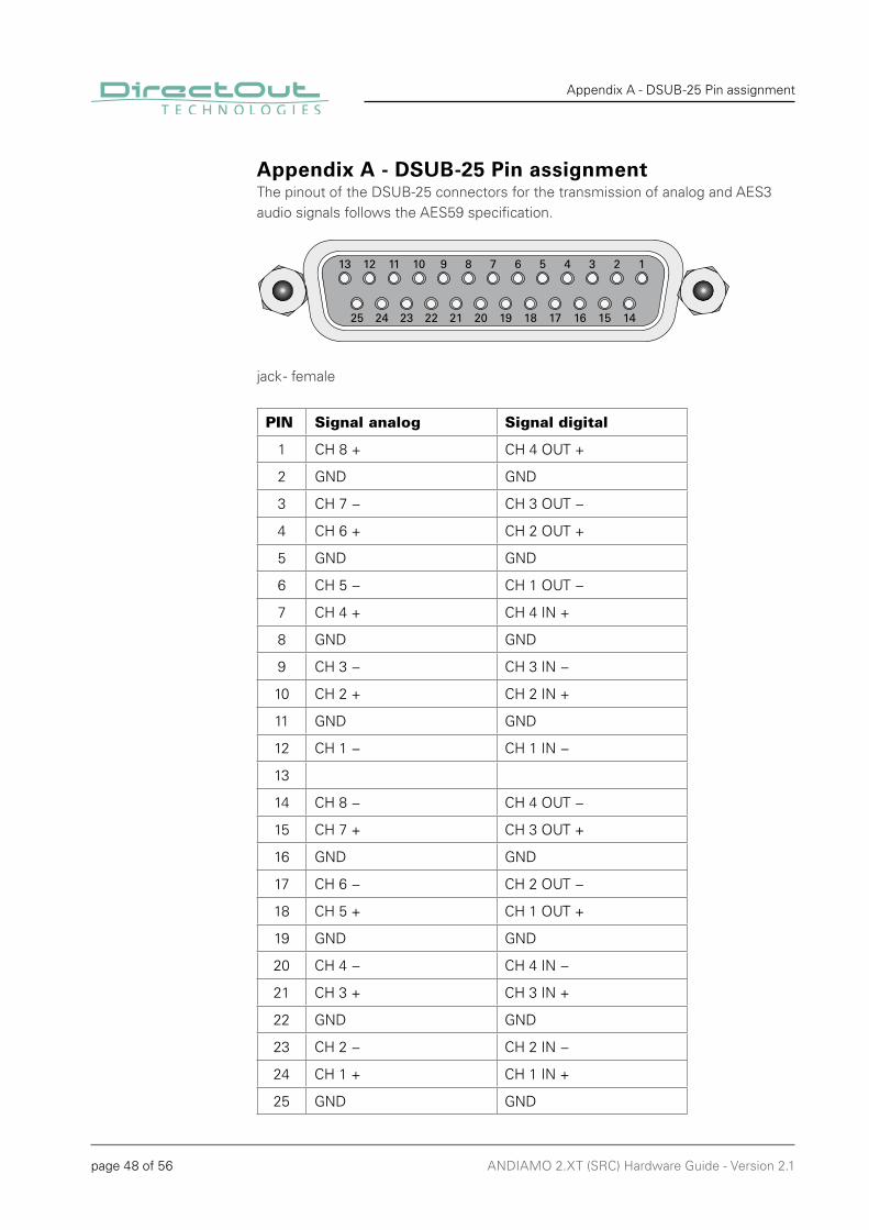
Appendix A - DSUB-25 Pin assignmentThe pinout of the DSUB-25 connectors for the transmission of analog and AES3 audio signals follows the AES59 specifi cation.
jack - female
PIN Signal analog Signal digital
1 CH 8 + CH 4 OUT +
2 GND GND
3 CH 7 − CH 3 OUT −
4 CH 6 + CH 2 OUT +
5 GND GND
6 CH 5 − CH 1 OUT −
7 CH 4 + CH 4 IN +
8 GND GND
9 CH 3 − CH 3 IN −
10 CH 2 + CH 2 IN +
11 GND GND
12 CH 1 − CH 1 IN −
13
14 CH 8 − CH 4 OUT −
15 CH 7 + CH 3 OUT +
16 GND GND
17 CH 6 − CH 2 OUT −
18 CH 5 + CH 1 OUT +
19 GND GND
20 CH 4 − CH 4 IN −
21 CH 3 + CH 3 IN +
22 GND GND
23 CH 2 − CH 2 IN −
24 CH 1 + CH 1 IN +
25 GND GND
13 12 11 10 9 8 7 6 5 4 3 2 1
25 24 23 22 21 20 19 18 17 16 15 14

page 49 of 56ANDIAMO 2.XT (SRC) Hardware Guide - Version 2.1
Appendix A - DSUB-25 Pin assignment
This page is left blank intentionally.
page 50 of 56 ANDIAMO 2.XT (SRC) Hardware Guide - Version 2.1
Index
Index
AAES59 ................................................ 39, 40
BBREAKOUT .............................................. 13
CClocking ................................................... 24
to AES .................................................. 25to MADI ............................................... 28
Conformity & CertificatesCE ........................................................ 11RoHS ................................................... 11WEEE .................................................. 11
Contact .................................................... 11Contents .................................................. 12Conventions ............................................... 5
DDefective Parts/Modules ........................... 8Delay Compensation ............................... 36Digital gain ............................................... 31Dimensions .............................................. 46DSUB-25 .................................................. 48
EEnvironmental Conditions .................. 15, 46Extended Routing .................................... 35
FFallback mode .......................................... 36Feature Summary ...................................... 7Firmware check ....................................... 17First Aid ..................................................... 9Frequency response ................................ 47Fuses ....................................................... 46
IImpedance (input/output) ........................ 47Intended Operation .................................. 10
LLatency (AD/DA) ...................................... 47Level
Meters analog ..................................... 32Meters digital ...................................... 33Model .................................................. 31Settings ............................................... 31
Level (input / output) ................................ 47Load Resistance (output) ......................... 47Local Operation see Menu Navigation
MMatrix Mode ............................................ 35Menu Control ........................................... 22Menu Navigation ..................................... 42
PPatch Chords ........................................... 14Pinout see DSUB-25
RRedundancy Modes ................................. 37Remote Control .................................... 7, 23Routing Matrix ......................................... 37
SSample Rate ............................................ 47Sample Rate Converter see SRC PerformanceSample Rate Selection............................. 29Scaling Factor .......................................... 20Signal Routing .......................................... 34
Bank Routing ....................................... 34SNR (AD & DA) ........................................ 47SRC Performance .................................... 47Support .................................................... 45System Settings ...................................... 43
TTechnical Data .......................................... 46THD (AD & DA) ........................................ 47Troubleshooting ....................................... 45
page 51 of 56ANDIAMO 2.XT (SRC) Hardware Guide - Version 2.1
Index
UUpdates ................................................... 10USB ........................................................... 7
WWarranty .................................................. 10

page 52 of 56 ANDIAMO 2.XT (SRC) Hardware Guide - Version 2.1
Notes

page 53 of 56ANDIAMO 2.XT (SRC) Hardware Guide - Version 2.1
Notes

page 54 of 56 ANDIAMO 2.XT (SRC) Hardware Guide - Version 2.1
Notes

page 55 of 56ANDIAMO 2.XT (SRC) Hardware Guide - Version 2.1
Notes

DirectOut GmbH T: +49-3727-5665-100F: +49-3727-5665-101www.directout.eu
Leipziger Strasse 3209648 MittweidaGermany