Embed Size (px)
Citation preview

Andrew MossDaresbury Laboratory
Collaboration Meeting 3415th 19th October 2012
RAL
MICE RF System review
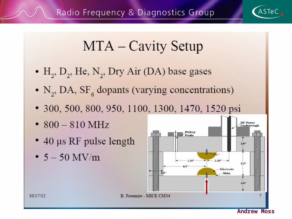
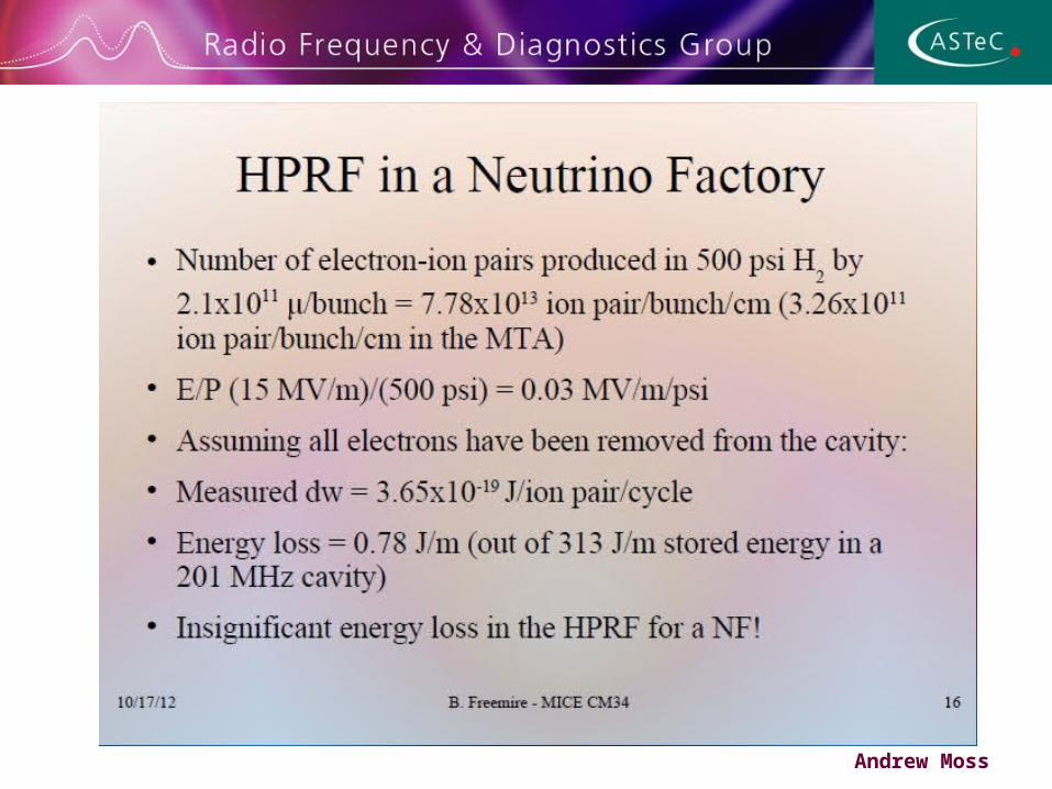
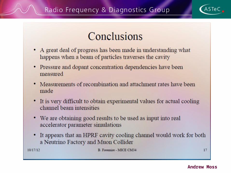
Contents• Amplifier update and status• Amplifier testing• Results of RF review• Hall layout• LLRF• First results from High Pressure Gas Filled RF
Cavity Beam Test at the MTA• Progress on Cavities for MICE• Conclusion
Andrew Moss

RF system components
Andrew Moss
2 MW Amplifier
2 MW Amplifier
Master OscillatorControls etc
201 MHz Cavity Module
2 MW Amplifier
2 MW Amplifier
201 MHz Cavity Module
LBNL CERN
250 kW Amplifier
250 kW Amplifier
250 kW Amplifier
250 kW Amplifier
HT Supplies
HT Supplies
Daresbury
DL Test SystemAt present
Auxiliary Systems
Auxiliary Systems
NEW
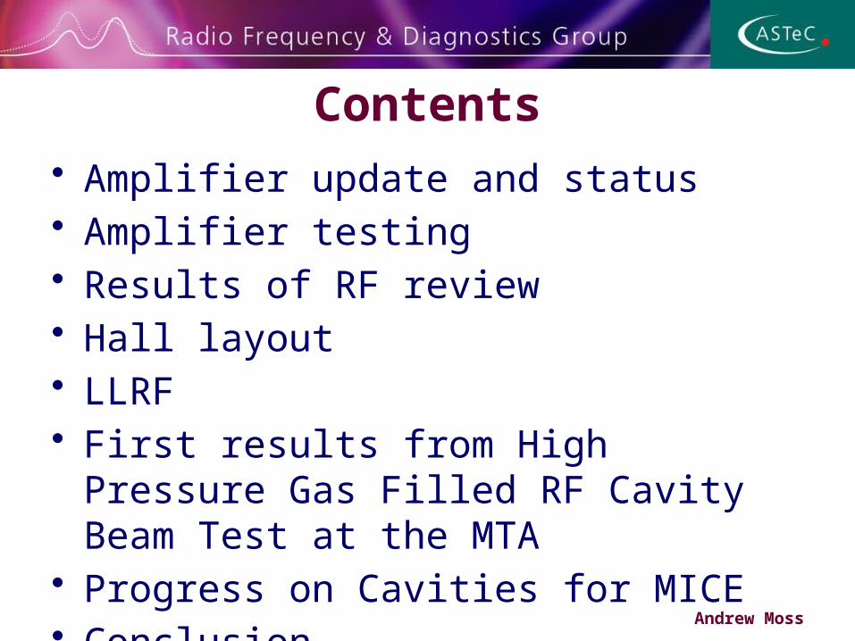
Test system at Daresbury
Andrew Moss
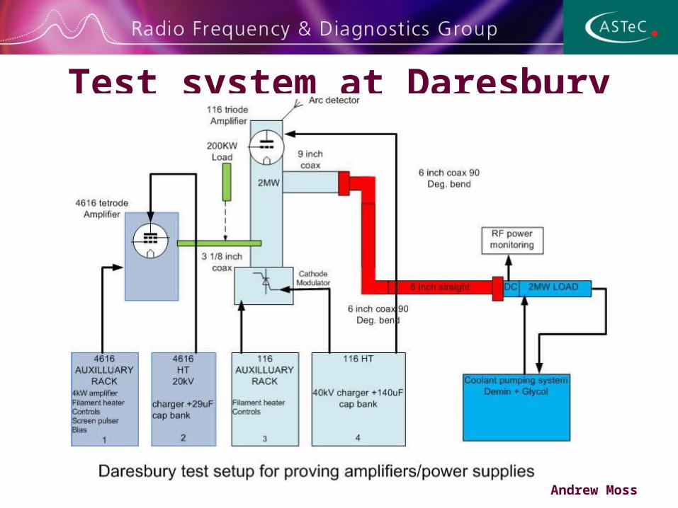
Status of Amplifier s and power supplies
• Test bay at DL is operational and able to test amplifiers and power supplies as they become available
• New 250 kW amplifier has been bought, and has been under test at the manufacturers
• First 250kW amplifier has operated at 100kW with old tube, then 240kW with new tube fitted during 2012
• First TH116 high power amplifier has operated at 1MW during 2011 using an old RAL tube – new MICE tube fitted, has operated at 1.2MW for short time
• Two further 250kW amplifiers are being refurbished now• Two refurbished 2MW CERN amplifiers refurbished but awaiting
assembly and high power test• Still need to build 3 more sets of power supplies – including set for TIARA
tests in experimental hall September 2013
Andrew Moss
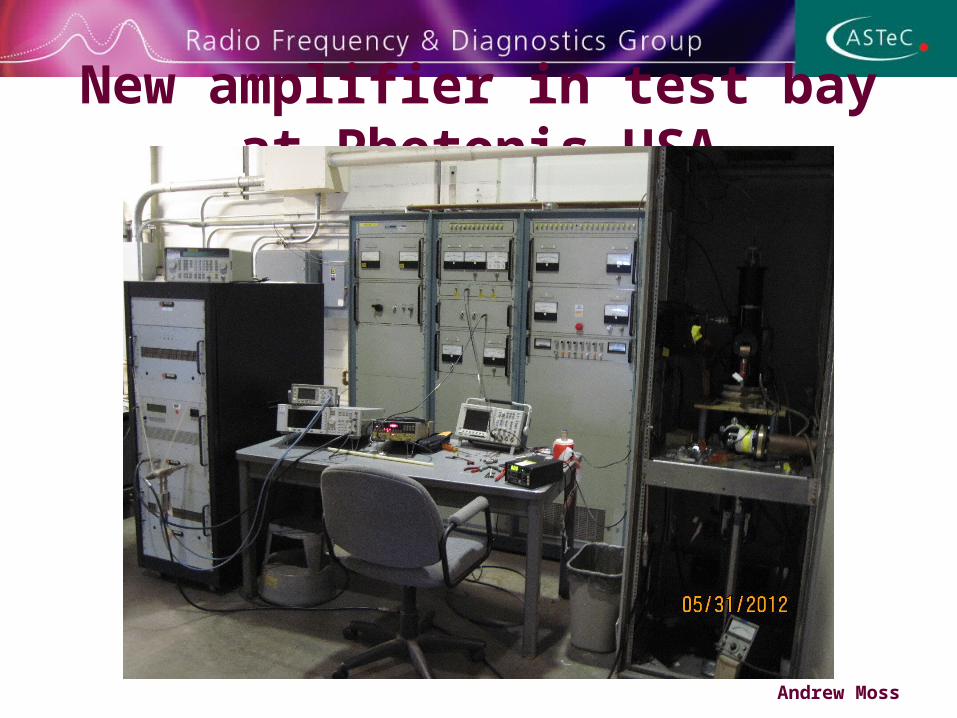
New amplifier in test bay at Photonis USA
Andrew Moss

New 250kW amplifier cavity
Andrew Moss
New amplifier operating at 240MHz (driver low on gain at 201MHz)
Delivered to Mississippi on 8th June 2012
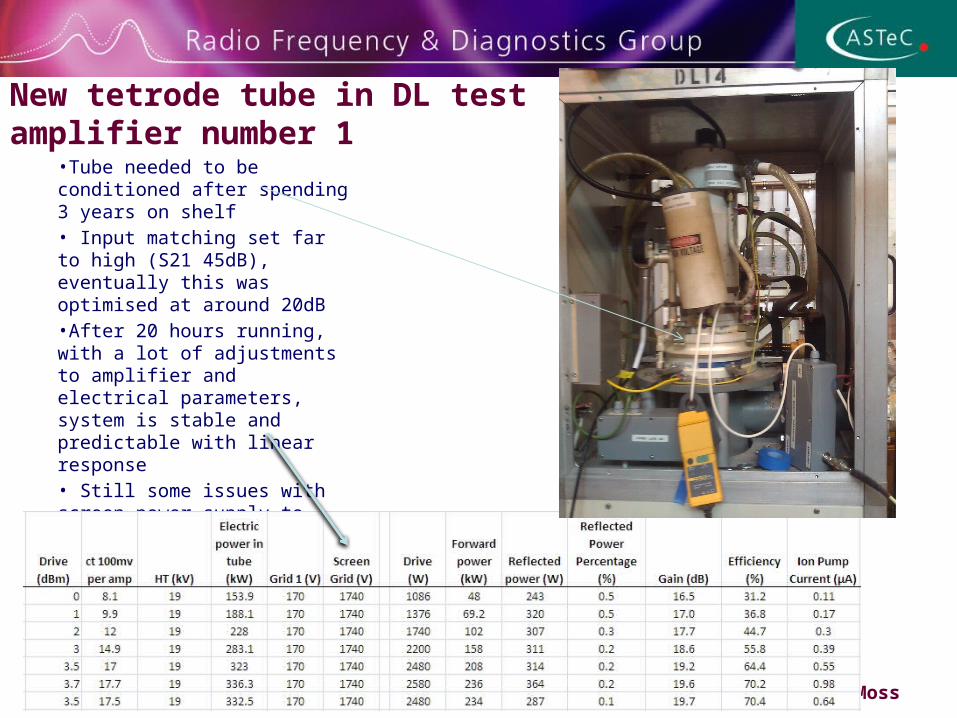
New tetrode tube in DL test amplifier number 1
•Tube needed to be conditioned after spending 3 years on shelf• Input matching set far to high (S21 45dB), eventually this was optimised at around 20dB•After 20 hours running, with a lot of adjustments to amplifier and electrical parameters, system is stable and predictable with linear response• Still some issues with screen power supply to sort out – loading of screen is moving with beam current and output loading
Andrew Moss
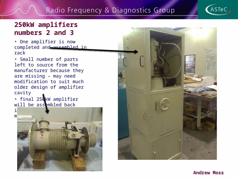
250kW amplifiers numbers 2 and 3 • One amplifier is now completed and assembled in rack• Small number of parts left to source from the manufacturer because they are missing – may need modification to suit much older design of amplifier cavity• final 250kW amplifier will be assembled back into rack in the next few months
Andrew Moss
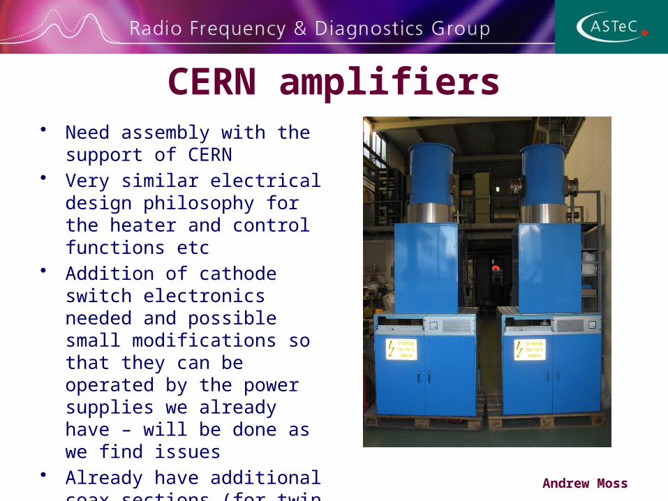
CERN amplifiers• Need assembly with the support
of CERN • Very similar electrical design
philosophy for the heater and control functions etc
• Addition of cathode switch electronics needed and possible small modifications so that they can be operated by the power supplies we already have – will be done as we find issues
• Already have additional coax sections (for twin output couplers) and second test load
Andrew Moss
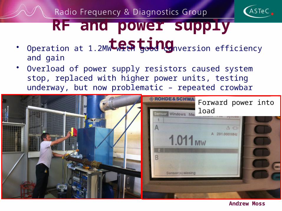
RF and power supply testing• Operation at 1.2MW with good conversion efficiency and gain
• Overload of power supply resistors caused system stop, replaced with higher power units, testing underway, but now problematic – repeated crowbar events
• Suspect tube needs to be conditioned, next week?
Andrew Moss
Forward power into load
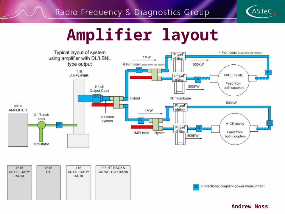
Amplifier layout
Andrew Moss
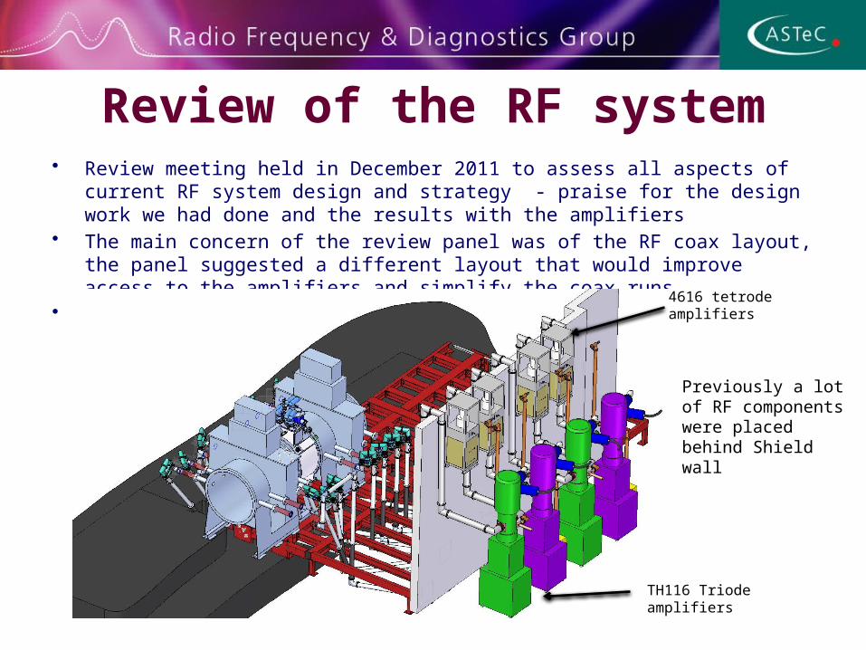
Review of the RF system• Review meeting held in December 2011 to assess all aspects of current RF system design and
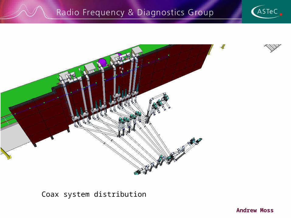
strategy - praise for the design work we had done and the results with the amplifiers • The main concern of the review panel was of the RF coax layout, the panel suggested a
different layout that would improve access to the amplifiers and simplify the coax runs. • This was taken on board and a new layout designed
Previously a lot of RF components were placed behind Shield wall
TH116 Triode amplifiers
4616 tetrode amplifiers
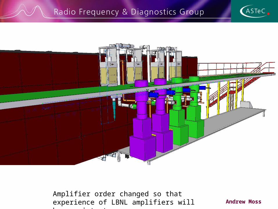
Andrew MossAmplifier order changed so that experience of LBNL amplifiers will be consistent
Andrew Moss
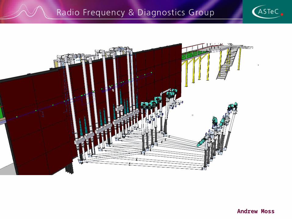
Coax system distribution
Andrew Moss
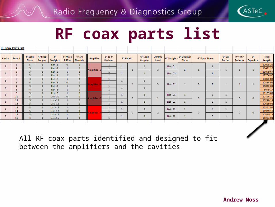
RF coax parts list
Andrew Moss
All RF coax parts identified and designed to fit between the amplifiers and the cavities

Coax power and Losses • Assuming 2MW from the amplifier and 500kW for each cavity
coupler• Using calculations obtained from MEGA, the peak standoff for 6
inch coax with MICE parameters is 3MW, for 4 inch coax it is 1.4MW
• With N2 gas at 1.5Bar this rises 3.6MW and 1.68MW respectively• Using slow cavity filling technique the reflected power from the
cavity can be substantially reduced (P forward + P reflected = P total) we expect P reflected to be less than 20% of P forward = peak standoff will not be exceeded at start of each pulse
• Calculations of attenuation and hence power loss though coax is 10% per cavity coupler, which will reduce gradient available, overdriving amplifier maybe possible with reduced reliability – still need to test this
Andrew Moss
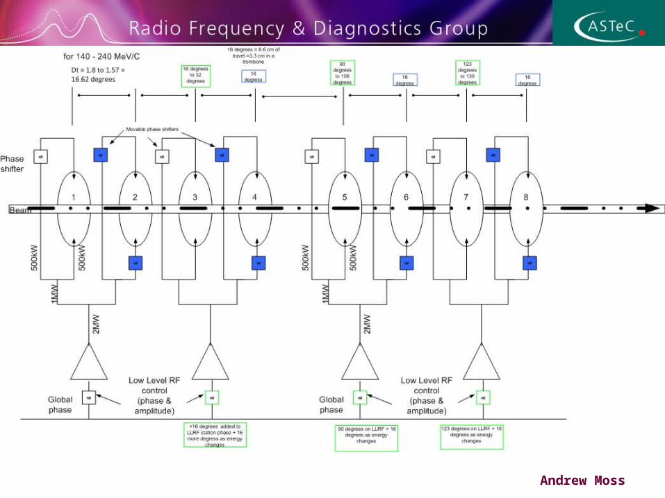
RF phasing
Andrew Moss

RF to beam synchronisation• Cavity phase and amplitude will be stabilised to 0.5 deg and
1% with the ability to run as high a gradient as possible• Muon particles will arrive randomly in the cooling channel for
acceleration at various phase angles • Cavity phase angle will have to be measured for each moun
and time stamped for analysis after a period of running• Time of flight detectors along the cooling channel will be used
to trigger electronics to measure and digitise the state of the cavity phase angle to < 15 pS
• Groups from Sheffield and Strathclyde University’s in conjunction with DL and LBNL are working on possible solutions for this area of the experiment
Andrew Moss
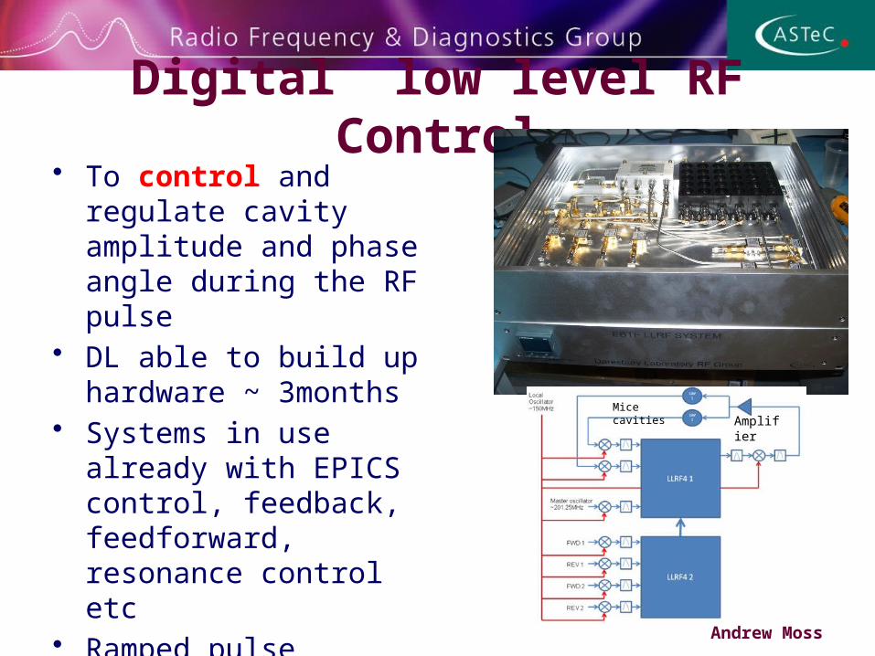
Digital low level RF Control• To control and regulate
cavity amplitude and phase angle during the RF pulse
• DL able to build up hardware ~ 3months
• Systems in use already with EPICS control, feedback, feedforward, resonance control etc
• Ramped pulse structure to limit reflected power tested on bench with 1.3GHz cavity
Andrew Moss
AmplifierMice cavities
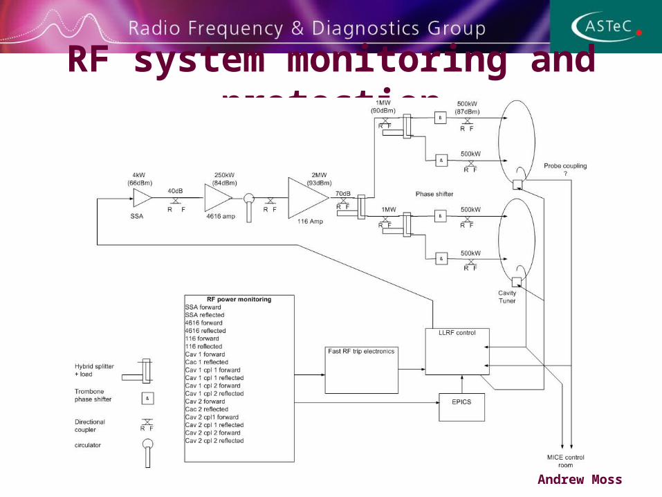
RF system monitoring and protection
Andrew Moss
Andrew Moss
Andrew Moss
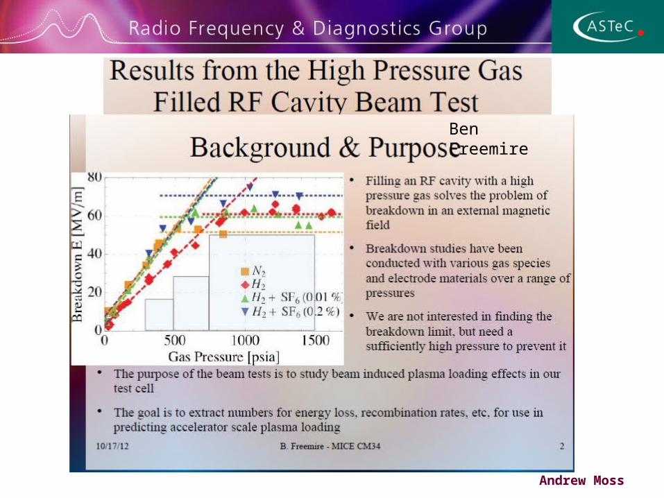
Ben Freemire
Andrew Moss
Andrew Moss
Andrew Moss

Summary• Progress on all three 250kW amplifiers including new system
in USA• Tested first MICE high power tube and system to 1.2MW,
some issues to resolve before 2MW • We plan to replicate the power supplies and install and test
them at DL – this will allow testing to continue, then move one set of amplifiers and power supplies to the MICE hall for September 2013
• RF review has prompted a new round of optimisation of coax distribution that looks to make things easier in a number of areas, space around the amplifiers, lower transmission loss, easier to install
• Ready to procure coax Andrew Moss
Page 29Page
29
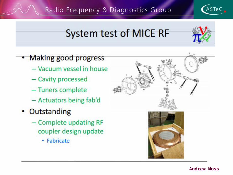
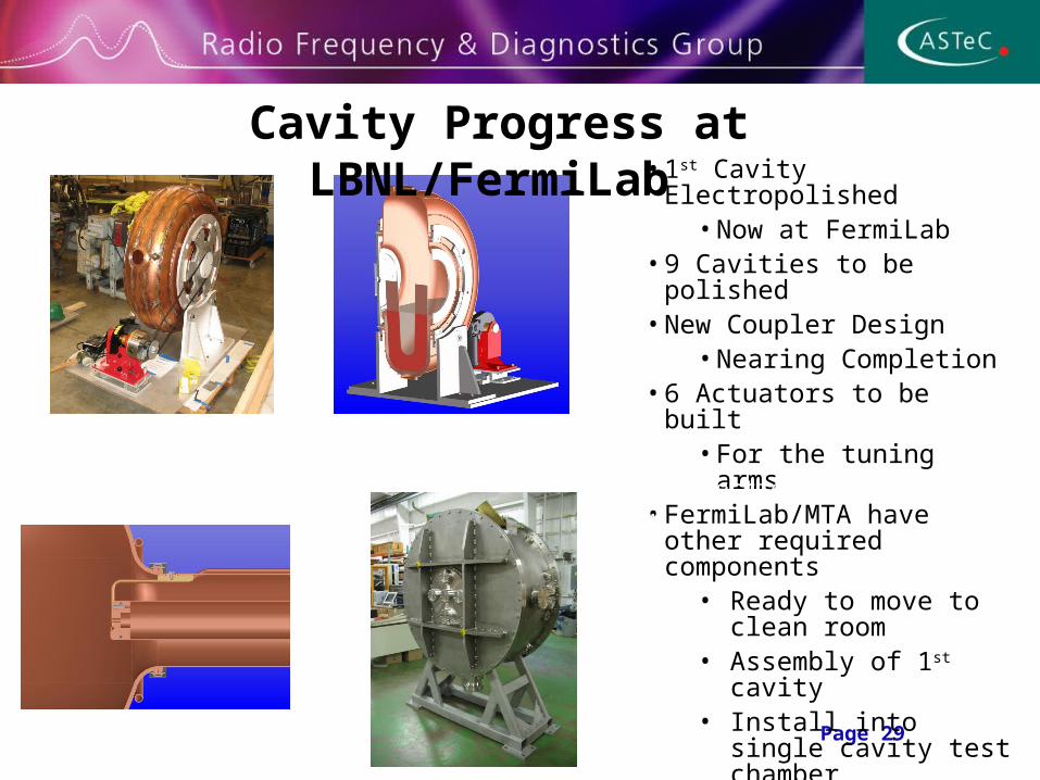
Cavity Progress at LBNL/FermiLab • 1st Cavity Electropolished
• Now at FermiLab• 9 Cavities to be polished• New Coupler Design
• Nearing Completion• 6 Actuators to be built
• For the tuning arms• FermiLab/MTA have other
required components • Ready to move to clean
room• Assembly of 1st cavity• Install into single cavity
test chamber• Testing initially in fringing
field• ~1T
Cavity section view

Page 30Page
30
Revision to RF layout
• Proposed change to layout• Pairing of identical amplifier
assemblies• Should afford efficiency in
running up• Two hybrids move to the
amplifier side of the shield wall
• Line lengths re-matched by sections lying along the top of the shield wall
• No interference with crane service
Cavity section view
Original Arrangement
Revised Arrangement
Page 31Page
31
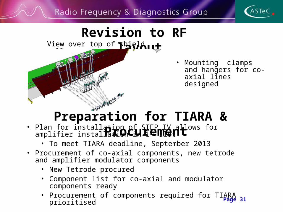
Revision to RF layout
Cavity section view
Preparation for TIARA & Procurement• Plan for installation of STEP IV allows for amplifier installation in 1st
slot• To meet TIARA deadline, September 2013
• Procurement of co-axial components, new tetrode and amplifier modulator components
• New Tetrode procured• Component list for co-axial and modulator components ready• Procurement of components required for TIARA prioritised
View over top of shield wall
• Mounting clamps and hangers for co-axial lines designed