Embed Size (px)
Citation preview
Sense & Control
Appl icat ion Note Ver. 1.0, 2014-12-03
Magnet ic Design Tool
TLE5009(D)TLE5011 TLE5012B(D) TLE5309D TLE5014
Angle SensorsxMR-Based Angular Sensors
Edition 2014-12-03Published byInfineon Technologies AG81726 Munich, Germany© 2014 Infineon Technologies AGAll Rights Reserved.
Legal DisclaimerThe information given in this document shall in no event be regarded as a guarantee of conditions or characteristics. With respect to any examples or hints given herein, any typical values stated herein and/or any information regarding the application of the device, Infineon Technologies hereby disclaims any and all warranties and liabilities of any kind, including without limitation, warranties of non-infringement of intellectual property rights of any third party.
InformationFor further information on technology, delivery terms and conditions and prices, please contact the nearest Infineon Technologies Office (www.infineon.com).
WarningsDue to technical requirements, components may contain dangerous substances. For information on the types in question, please contact the nearest Infineon Technologies Office.Infineon Technologies components may be used in life-support devices or systems only with the express written approval of Infineon Technologies, if a failure of such components can reasonably be expected to cause the failure of that life-support device or system or to affect the safety or effectiveness of that device or system. Life support devices or systems are intended to be implanted in the human body or to support and/or maintain and sustain and/or protect human life. If they fail, it is reasonable to assume that the health of the user or other persons may be endangered.
Magnetic Design Toolfor Angle Sensors
Application Note 3 Ver. 1.0, 2014-12-03
Trademarks of Infineon Technologies AGAURIX™, C166™, CanPAK™, CIPOS™, CIPURSE™, EconoPACK™, CoolMOS™, CoolSET™,CORECONTROL™, CROSSAVE™, DAVE™, DI-POL™, EasyPIM™, EconoBRIDGE™, EconoDUAL™,EconoPIM™, EconoPACK™, EiceDRIVER™, eupec™, FCOS™, HITFET™, HybridPACK™, I²RF™,ISOFACE™, IsoPACK™, MIPAQ™, ModSTACK™, my-d™, NovalithIC™, OptiMOS™, ORIGA™,POWERCODE™; PRIMARION™, PrimePACK™, PrimeSTACK™, PRO-SIL™, PROFET™, RASIC™,ReverSave™, SatRIC™, SIEGET™, SINDRION™, SIPMOS™, SmartLEWIS™, SOLID FLASH™, TEMPFET™,thinQ!™, TRENCHSTOP™, TriCore™.
Other TrademarksAdvance Design System™ (ADS) of Agilent Technologies, AMBA™, ARM™, MULTI-ICE™, KEIL™,PRIMECELL™, REALVIEW™, THUMB™, µVision™ of ARM Limited, UK. AUTOSAR™ is licensed by AUTOSARdevelopment partnership. Bluetooth™ of Bluetooth SIG Inc. CAT-iq™ of DECT Forum. COLOSSUS™,FirstGPS™ of Trimble Navigation Ltd. EMV™ of EMVCo, LLC (Visa Holdings Inc.). EPCOS™ of Epcos AG.FLEXGO™ of Microsoft Corporation. FlexRay™ is licensed by FlexRay Consortium. HYPERTERMINAL™ ofHilgraeve Incorporated. IEC™ of Commission Electrotechnique Internationale. IrDA™ of Infrared DataAssociation Corporation. ISO™ of INTERNATIONAL ORGANIZATION FOR STANDARDIZATION. MATLAB™ ofMathWorks, Inc. MAXIM™ of Maxim Integrated Products, Inc. MICROTEC™, NUCLEUS™ of Mentor GraphicsCorporation. MIPI™ of MIPI Alliance, Inc. MIPS™ of MIPS Technologies, Inc., USA. muRata™ of MURATAMANUFACTURING CO., MICROWAVE OFFICE™ (MWO) of Applied Wave Research Inc., OmniVision™ ofOmniVision Technologies, Inc. Openwave™ Openwave Systems Inc. RED HAT™ Red Hat, Inc. RFMD™ RFMicro Devices, Inc. SIRIUS™ of Sirius Satellite Radio Inc. SOLARIS™ of Sun Microsystems, Inc. SPANSION™of Spansion LLC Ltd. Symbian™ of Symbian Software Limited. TAIYO YUDEN™ of Taiyo Yuden Co.TEAKLITE™ of CEVA, Inc. TEKTRONIX™ of Tektronix Inc. TOKO™ of TOKO KABUSHIKI KAISHA TA. UNIX™of X/Open Company Limited. VERILOG™, PALLADIUM™ of Cadence Design Systems, Inc. VLYNQ™ of TexasInstruments Incorporated. VXWORKS™, WIND RIVER™ of WIND RIVER SYSTEMS, INC. ZETEX™ of DiodesZetex Limited.Last Trademarks Update 2011-11-11
Revision HistoryPage or Item Subjects (major changes since previous revision)Ver. 1.0, 2014-12-03
Magnetic Design Toolfor Angle Sensors
Table of Contents
Application Note 4 Ver. 1.0, 2014-12-03
Table of Contents . . . . . . . . . . . . . . . . . . . . . . . . . . . . . . . . . . . . . . . . . . . . . . . . . . . . . . . . . . . . . . . . 4
List of Figures . . . . . . . . . . . . . . . . . . . . . . . . . . . . . . . . . . . . . . . . . . . . . . . . . . . . . . . . . . . . . . . . . . . 5
1 Introduction . . . . . . . . . . . . . . . . . . . . . . . . . . . . . . . . . . . . . . . . . . . . . . . . . . . . . . . . . . . . . . . . . . . . . 6
2 Data inputs . . . . . . . . . . . . . . . . . . . . . . . . . . . . . . . . . . . . . . . . . . . . . . . . . . . . . . . . . . . . . . . . . . . . . 72.1 Magnetic Properties . . . . . . . . . . . . . . . . . . . . . . . . . . . . . . . . . . . . . . . . . . . . . . . . . . . . . . . . . . . . . . . 72.2 Sensor Specification . . . . . . . . . . . . . . . . . . . . . . . . . . . . . . . . . . . . . . . . . . . . . . . . . . . . . . . . . . . . . . . 82.3 Assembly Tolerances . . . . . . . . . . . . . . . . . . . . . . . . . . . . . . . . . . . . . . . . . . . . . . . . . . . . . . . . . . . . . . 9
3 Start simulation . . . . . . . . . . . . . . . . . . . . . . . . . . . . . . . . . . . . . . . . . . . . . . . . . . . . . . . . . . . . . . . . . 113.1 Magnet Field at Sensor . . . . . . . . . . . . . . . . . . . . . . . . . . . . . . . . . . . . . . . . . . . . . . . . . . . . . . . . . . . . 113.2 Worst Case Angle Error due to Assembly Tolerances . . . . . . . . . . . . . . . . . . . . . . . . . . . . . . . . . . . . 12
References . . . . . . . . . . . . . . . . . . . . . . . . . . . . . . . . . . . . . . . . . . . . . . . . . . . . . . . . . . . . . . . . . . . . 13
Table of Contents
Magnetic Design Toolfor Angle Sensors
List of Figures
Application Note 5 Ver. 1.0, 2014-12-03
Figure 1 Magnetic Design Tool Angle Sensors interface . . . . . . . . . . . . . . . . . . . . . . . . . . . . . . . . . . . . . . . . 6Figure 2 Magnetic Properties (e.g. 400mT magnet with 4mm thickness and 12mm diameter) . . . . . . . . . . . 7Figure 3 Sensor Specification (e.g. TLE5009 magnetic field specification) . . . . . . . . . . . . . . . . . . . . . . . . . . 8Figure 4 Magnetic field specifications from data sheet (e.g. TLE5009 operating range).. . . . . . . . . . . . . . . . 8Figure 5 Assembly Tolerances . . . . . . . . . . . . . . . . . . . . . . . . . . . . . . . . . . . . . . . . . . . . . . . . . . . . . . . . . . . . 9Figure 6 Air gap definition . . . . . . . . . . . . . . . . . . . . . . . . . . . . . . . . . . . . . . . . . . . . . . . . . . . . . . . . . . . . . . . . 9Figure 7 START and SAVE SIMULATION menu . . . . . . . . . . . . . . . . . . . . . . . . . . . . . . . . . . . . . . . . . . . . . 11Figure 8 Magnet Field at Sensor (e.g. simulated magnet enables air gaps between 0.7mm and 4.1mm). . 11Figure 9 Angle Error due to Assembly Tolerances (e.g. 0.61° assembly error with a 12mm diameter) . . . . 12
List of Figures
Magnetic Design Toolfor Angle Sensors
Introduction
Application Note 6 Ver. 1.0, 2014-12-03
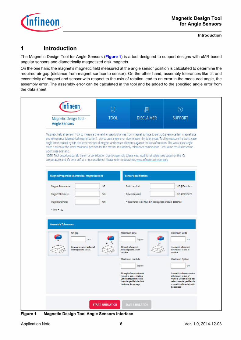
1 IntroductionThe Magnetic Design Tool for Angle Sensors (Figure 1) is a tool designed to support designs with xMR-basedangular sensors and diametrically magnetized disk magnets. On the one hand the magnet’s magnetic field measured at the angle sensor position is calculated to determine therequired air-gap (distance from magnet surface to sensor). On the other hand, assembly tolerances like tilt andeccentricity of magnet and sensor with respect to the axis of rotation lead to an error in the measured angle, theassembly error. The assembly error can be calculated in the tool and be added to the specified angle error fromthe data sheet.
Figure 1 Magnetic Design Tool Angle Sensors interface
Magnetic Design Toolfor Angle Sensors
Data inputs
Application Note 7 Ver. 1.0, 2014-12-03
2 Data inputsTo simulate the magnetic field and the assembly error the following inputs are required:• Magnetic Properties (description in Chapter 2.1)• Sensor Specifications (description in Chapter 2.2)• Assembly Tolerances (description in Chapter 2.3)
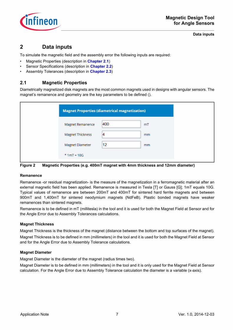
2.1 Magnetic PropertiesDiametrically magnetized disk magnets are the most common magnets used in designs with angular sensors. Themagnet’s remanence and geometry are the key parameters to be defined ().
Figure 2 Magnetic Properties (e.g. 400mT magnet with 4mm thickness and 12mm diameter)
RemanenceRemanence -or residual magnetization- is the measure of the magnetization in a ferromagnetic material after anexternal magnetic field has been applied. Remanence is measured in Tesla [T] or Gauss [G]; 1mT equals 10G.Typical values of remanence are between 200mT and 400mT for sintered hard ferrite magnets and between900mT and 1,400mT for sintered neodymium magnets (NdFeB). Plastic bonded magnets have weakerremanences than sintered magnets.Remanence is to be defined in mT (millitesla) in the tool and it is used for both the Magnet Field at Sensor and forthe Angle Error due to Assembly Tolerances calculations.
Magnet ThicknessMagnet Thickness is the thickness of the magnet (distance between the bottom and top surfaces of the magnet).Magnet Thickness is to be defined in mm (millimeters) in the tool and it is used for both the Magnet Field at Sensorand for the Angle Error due to Assembly Tolerance calculations.
Magnet DiameterMagnet Diameter is the diameter of the magnet (radius times two).Magnet Diameter is to be defined in mm (millimeters) in the tool and it is only used for the Magnet Field at Sensorcalculation. For the Angle Error due to Assembly Tolerance calculation the diameter is a variable (x-axis).
Magnetic Design Toolfor Angle Sensors
Data inputs
Application Note 8 Ver. 1.0, 2014-12-03
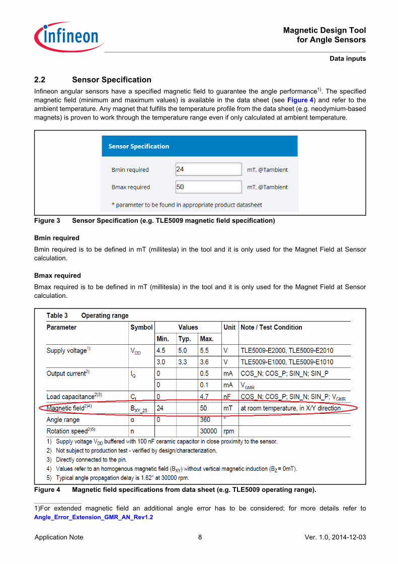
2.2 Sensor SpecificationInfineon angular sensors have a specified magnetic field to guarantee the angle performance1). The specifiedmagnetic field (minimum and maximum values) is available in the data sheet (see Figure 4) and refer to theambient temperature. Any magnet that fulfills the temperature profile from the data sheet (e.g. neodymium-basedmagnets) is proven to work through the temperature range even if only calculated at ambient temperature.
Figure 3 Sensor Specification (e.g. TLE5009 magnetic field specification)
Bmin requiredBmin required is to be defined in mT (millitesla) in the tool and it is only used for the Magnet Field at Sensorcalculation.
Bmax requiredBmax required is to be defined in mT (millitesla) in the tool and it is only used for the Magnet Field at Sensorcalculation.
Figure 4 Magnetic field specifications from data sheet (e.g. TLE5009 operating range).
1)For extended magnetic field an additional angle error has to be considered; for more details refer toAngle_Error_Extension_GMR_AN_Rev1.2
Magnetic Design Toolfor Angle Sensors
Data inputs
Application Note 9 Ver. 1.0, 2014-12-03
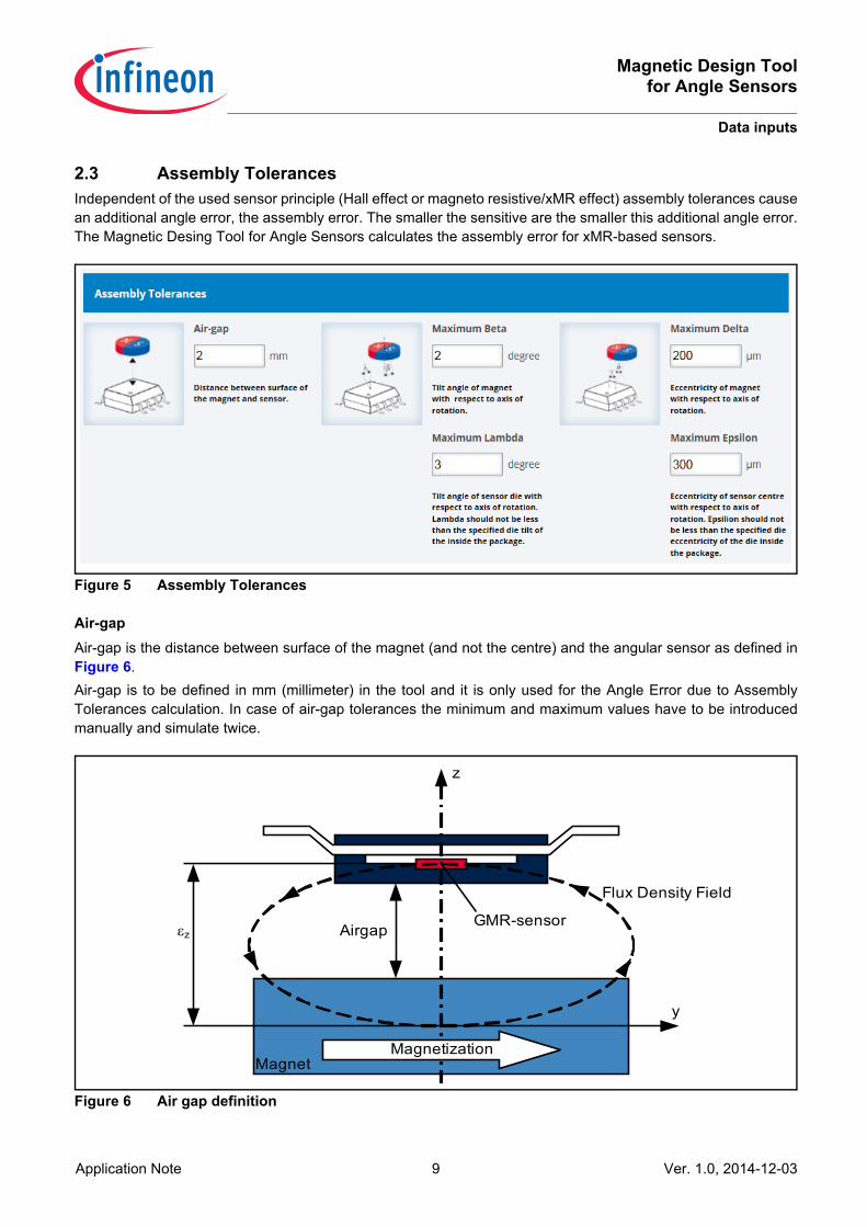
2.3 Assembly TolerancesIndependent of the used sensor principle (Hall effect or magneto resistive/xMR effect) assembly tolerances causean additional angle error, the assembly error. The smaller the sensitive are the smaller this additional angle error.The Magnetic Desing Tool for Angle Sensors calculates the assembly error for xMR-based sensors.
Figure 5 Assembly Tolerances
Air-gapAir-gap is the distance between surface of the magnet (and not the centre) and the angular sensor as defined inFigure 6.Air-gap is to be defined in mm (millimeter) in the tool and it is only used for the Angle Error due to AssemblyTolerances calculation. In case of air-gap tolerances the minimum and maximum values have to be introducedmanually and simulate twice.
Figure 6 Air gap definition
εz
y
z
Flux Density Field
GMR-sensor
MagnetMagnetization
Airgap
Magnetic Design Toolfor Angle Sensors
Data inputs
Application Note 10 Ver. 1.0, 2014-12-03
Maximum BetaMaximum Beta is the tilt of the magnet with respect to axis of rotation.Maximum Beta is to be defined in ° (angle degrees) in the tool and it is only used for the Angle Error due toAssembly Tolerances calculation.
Maximum LambdaMaximum Lambda is the tilt of the angular sensor with respect to axis of rotation.Maximum Lambda is to be defined in ° (angle degrees) in the tool and it is only used for the Angle Error due toAssembly Tolerances calculation.
Maximum DeltaMaximum Delta is the eccentricity of magnet with respect to axis of rotation.Maximum Delta is to be defined in µm (micrometers) in the tool and it is only used for the Angle Error due toAssembly Tolerances calculation.
Maximum EpsilonMaximum Epsilon is the eccentricity of the angular sensor with respect to axis of rotation.Maximum Epsilon is to be defined in µm (micrometers) in the tool and it is only used for the Angle Error due toAssembly Tolerances calculation.
Magnetic Design Toolfor Angle Sensors
Start simulation
Application Note 11 Ver. 1.0, 2014-12-03
3 Start simulationOnce the magnet has been defined and all the required data fields completed it is possible to proceed with thecalculations by clicking “START SIMULATION”.This calculation considers no influence of other magnetic fields or magnetic materials such as iron or magneticsteels. Therefore, shafts of non magnetic materials such as aluminum are assumed.The points of the curve can be read by placing the mouse on top of the graph. Additionaly a report with the inputdata, the graphs and a table with the points is provided when clicking “SAVE SIMULATION”.
Figure 7 START and SAVE SIMULATION menu
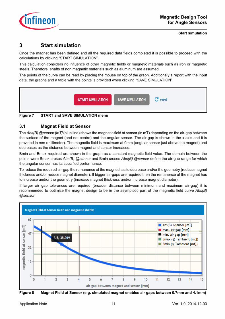
3.1 Magnet Field at SensorThe Abs(B) @sensor [mT] (blue line) shows the magnetic field at sensor (in mT) depending on the air-gap betweenthe surface of the magnet (and not centre) and the angular sensor. The air-gap is shown in the x-axis and it isprovided in mm (millimeter). The magnetic field is maximum at 0mm (angular sensor just above the magnet) anddecreases as the distance between magnet and sensor increases.Bmin and Bmax required are shown in the graph as a constant magnetic field value. The domain between thepoints were Bmax croses Abs(B) @sensor and Bmin croses Abs(B) @sensor define the air-gap range for whichthe angular sensor has its specified performance.To reduce the required air-gap the remanence of the magnet has to decrease and/or the geometry (reduce magnetthickness and/or reduce magnet diameter). If bigger air-gaps are required then the remanence of the magnet hasto increase and/or the geometry (increase magnet thickness and/or increase magnet diameter).If larger air gap tolerances are required (broader distance between minimum and maximum air-gap) it isrecommended to optimize the magnet design to be in the asymptotic part of the magnetic field curve Abs(B)@sensor.
Figure 8 Magnet Field at Sensor (e.g. simulated magnet enables air gaps between 0.7mm and 4.1mm)
Magnetic Design Toolfor Angle Sensors
Start simulation
Application Note 12 Ver. 1.0, 2014-12-03
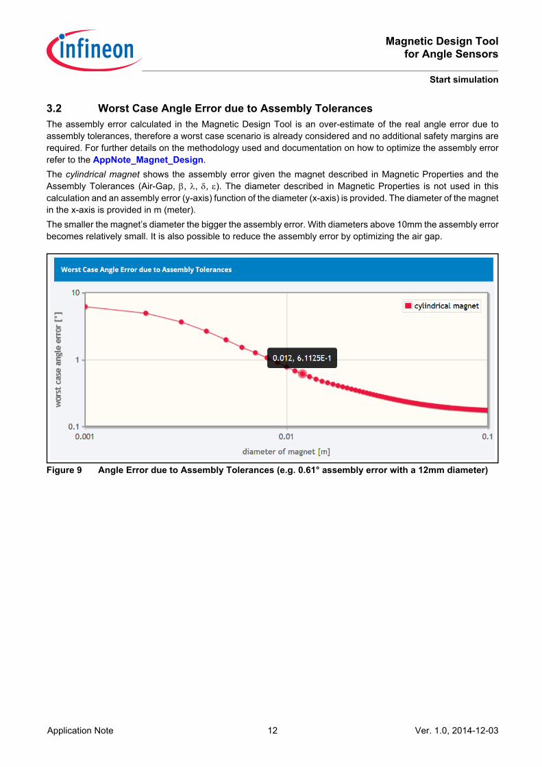
3.2 Worst Case Angle Error due to Assembly TolerancesThe assembly error calculated in the Magnetic Design Tool is an over-estimate of the real angle error due toassembly tolerances, therefore a worst case scenario is already considered and no additional safety margins arerequired. For further details on the methodology used and documentation on how to optimize the assembly errorrefer to the AppNote_Magnet_Design.The cylindrical magnet shows the assembly error given the magnet described in Magnetic Properties and theAssembly Tolerances (Air-Gap, β, λ, δ, ε). The diameter described in Magnetic Properties is not used in thiscalculation and an assembly error (y-axis) function of the diameter (x-axis) is provided. The diameter of the magnetin the x-axis is provided in m (meter).The smaller the magnet’s diameter the bigger the assembly error. With diameters above 10mm the assembly errorbecomes relatively small. It is also possible to reduce the assembly error by optimizing the air gap.
Figure 9 Angle Error due to Assembly Tolerances (e.g. 0.61° assembly error with a 12mm diameter)
Magnetic Design Toolfor Angle Sensors
References
Application Note 13 Ver. 1.0, 2014-12-03
References[1] U.Ausserlechner, “Inaccuracies of Giant Magneto-Resistive Angle Sensors due to Assembly Tolerances”,
IEEE Trans. Magn., May 2009, vol. 45, no. 5, pp. 2165-2174
[2] U.Ausserlechner, “Inaccuracies of Anisotropic Magneto-Resistant Angle Sensors due to Assembly Tolerances”, PIER B (Progress in Electromagnetics Research B), 2012, Vol. 40, pages 79-99