Embed Size (px)
Citation preview
Animating
Copyright and trademarks
StudioTools 13
Software copyright information is located in the application, and can be accessed from the menu by choosing Help > About StudioTools.
All documentation ("Documentation") is copyrighted © 2001-2005 Alias and contains proprietary and confidential information of Alias. The Documentation is protected by national and international intellectual property laws and treaties. All rights reserved. Use of the Documentation is subject to the terms of the license agreement that governs the use of the software product to which the Documentation pertains ("Software"). The authorized licensee of the Software is hereby authorized to print no more than one (1) hardcopy of any Documentation provided in digital format per valid license of the Software held by such licensee. Except for the foregoing, the Documentation may not be translated, copied or duplicated in any form (physically or electronically), in whole or in part, without the prior written consent of Alias.
Alias and the swirl logo, Maya and DesignStudio are registered trademarks and Alias Natural Phenomena, Alias OpenAlias, Alias OpenModel, Alias PowerCaster, Alias PowerTracer, Alias RayCasting, Alias RayTracing, Alias SDL, ImageStudio, Alias Spider, StudioPaint, StudioViewer, StudioTools and SurfaceStudio are trademarks of Alias Systems Corp. ("Alias") in the United States and/or other countries. Silicon Graphics, SGI and IRIX are registered trademarks and Inventor is a trademark of Silicon Graphic, Inc. in the United States and/or other countries worldwide. Microsoft and Windows are either registered trademarks or trademarks of Microsoft Corporation in the United States and/or other countries. Renderman is a registered trademark of Pixar Corporation. Apple, Quicktime and Macintosh are trademarks of Apple Computer, Inc. registered in the United States and other countries. Adobe, Postcript and Illustrator are either registered trademarks or trademarks of Adobe Systems Incorporated in the United States and/or other countries. Unigraphics, NX, and I-deas are registered trademarks or trademarks of UGS Corp. or its subsidiaries in the United States and in other countries. Arius3D is a registered trademark of Arius3D Inc. Cyberware is a registered trademark of Cyberware Laboratory Inc.. Cyrax is a registered trademark of Leica Geosystems HDS Inc. Steinbichler is a registered trademark of Steinbichler Optotechnik GmbH. Autodesk and AutoCAD are either registered trademarks or trademarks of Autodesk, Inc./Autodesk Canada, Inc. in the USA and/or other countries. CATIA is a registered trademark of Dassault Systèmes S.A. PTC, Pro/ENGINEER and Granite are trademarks or registered trademarks of Parametric Technology Corporation or its subsidiaries in the U.S. and in other countries. All other trademarks mentioned herein are the property of their respective owners.
All PTC Technology logos are used under license from Parametric Technology Corporation, Needham, MA, USA.
Not all features described are available in all products.
Alias Systems Corp., 210 King Street East, Toronto, Canada M5A 1J7
Contents
Contents i
Animating 1Introduction 3
What is animation? 4What can you animate? 5Basic workflow for manually creating an animation 6What happens when an item is animated? 8How can I tell if something is animated? 11What is a parameter curve action and a motion path action? 12What happens when you animate a camera on a curve? 15Can I reuse animation on another channel? 17What is inverse kinematics? 18What is a time warp curve? 20
How do I? 23
Create a turntable animation 24Create a turntable animation 25Use keyframes 28Edit a keyframe animation 30Playback the animation 33View individual frames of animation 35Preview a rendered animation with FlipBook (UNIX only) 36View images with fcheck (Windows only) 37Use Auto keyframe 45Create different segments of your animation 47Use the Play Blast window 48Edit the animation curve 50Move keyframes on an animation curve 52Create SGI and Apple format movie files (IRIX only) 53Add keyframes 54
iContents
Copy keyframes 55Cut keyframes 56Paste keyframes 58Animate objects along a motion path 60Set up a camera to travel along a motion path 62Edit the timing curve of a motion path 64Animate a camera on a motion path 69Edit a motion path in the Action Window 72Delete the animation for the object 74Create an exploded view animation 76Prevent collisions in your exploded view animation 80
Prepare to import or export 83Preview an animation without reducing the scene 84Expand a DAG node in the action lister 85Export animation channels 87Import animation 88
Create skeletons and inverse kinematics animation 89Overview on skeletons 90Draw a skeleton 93Display skeleton bones 95Add IK handles to your skeleton 96Creating a neutral pose for IK skeletons 99Returning joints and IK skeletons to a rest pose 102Find information on IK handles 105Turn IK handle display on or off 112Making a mirror copy 114Run IK to render your animation 116
Work with IK chain solvers 117Use the single-chain solver 118Create a simple spine chain 121Create a human-like character 122Use the multi-handle solver 126Overlap IK handles 128Set the IK handle rotation behavior 129Use the spline-handle solver 130Bake animation and use Motion Blur compensation 131Spline IK overview 132Spline handle information 135
Work with constraints 138Create a constraint on an object 139Constrain one object to another object 142Edit UV constraints 147
iiContents
Turn constraints on or off 148Turn constraint display on and off 149Delete constraints 150
Create animated deformed surfaces 151Create clusters 152Edit cluster attributes 155Add selection handles 163Change the form of original object in an animation 165Create clusters with properties for deformation 173
Apply a time warp 203Apply a time warp 204Cycle sections of animation with a time warp 205Scale animation timing with a time warp 206
Index 207
iiiContents

ivContents
AnimatingHow to animate objects and attributes in your scene.
1Animating

2Animating
IntroductionLearn what animation is, what you can animate and about the different animation techniques used.
3
What is animation?
Learn how animation is defined and used in StudioTools.
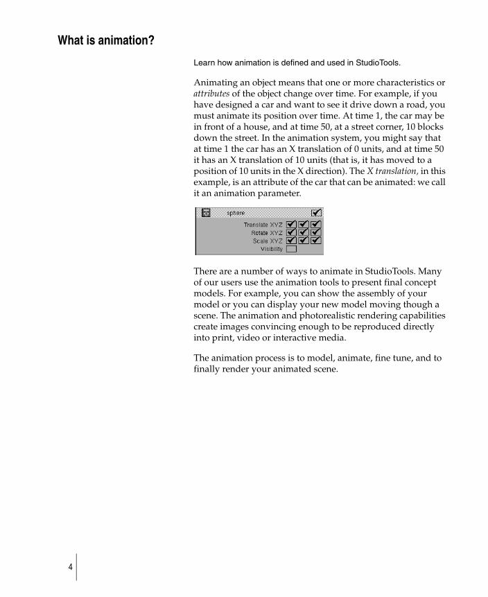
Animating an object means that one or more characteristics or attributes of the object change over time. For example, if you have designed a car and want to see it drive down a road, you must animate its position over time. At time 1, the car may be in front of a house, and at time 50, at a street corner, 10 blocks down the street. In the animation system, you might say that at time 1 the car has an X translation of 0 units, and at time 50 it has an X translation of 10 units (that is, it has moved to a position of 10 units in the X direction). The X translation, in this example, is an attribute of the car that can be animated: we call it an animation parameter.
There are a number of ways to animate in StudioTools. Many of our users use the animation tools to present final concept models. For example, you can show the assembly of your model or you can display your new model moving though a scene. The animation and photorealistic rendering capabilities create images convincing enough to be reproduced directly into print, video or interactive media.
The animation process is to model, animate, fine tune, and to finally render your animated scene.
4
What can you animate?
Learn about different levels of animation available in StudioTools.
An object generally has many attributes, or animation parameters, that can be animated. In StudioTools, a directed acyclic graph node has ten attributes that can be animated: the X, Y, and Z translation, rotation and scale attributes, and also the visibility.
Other types of objects have different animation parameters. For example, a camera’s angle of view can be animated, and a light can have its color or intensity animated. An object or other item that has at least one animation parameter or attribute that can be animated is called an animatable item.
StudioTools offers three different levels of animation
● Keyframe animation
◆ create a turntable animation
◆ create a motionpath animation
◆ add a camera to your animation
◆ create an exploded assembly view animation
● Skeleton and Inverse Kinematics
◆ create skeleton models
◆ apply IK handles to move parts of the skeleton
◆ use mathematical expressions to determine action and motion
● Advanced Animation
◆ animate and deform surfaces
◆ deform time with time warps
5
Basic workflow for manually creating an animation
Learn the process of modeling, animating, fine tuning, and finally rendering your animated scene.
StudioTools provides two types of automatic animation, where you plug in parameters and StudioTools creates the animation, as well as manual, freeform animation.
In StudioTools, manually creating animation involves establishing a timeline, then varying one or more properties of objects (for example, position or color) over time.
To apply the workflow
1 Create the model.
2 Decide how long you want the animation to be and create the necessary number of time frames in StudioTools.
3 Use basic techniques to vary the scene through the length of the animation:
◆ Place objects you want to animate, including the camera, where you want them, and with the values you want, at each point in the timeline, then mark those frames as keyframes.
or
◆ Establish motion paths for objects to move along through time.
For more advanced animation, StudioTools is capable of varying almost every property of an object or shader along the timeline, not just position.
4 Decide how the objects should transition from frame to frame.
More advanced animation can use the Action window, expressions (mathematical formulas describing relationships between time and object properties), and constraints, to create more realistic and automated effects.
5 Preview or render the animation.
6
Parameters
Objects have many parameters that can be animated. Examples are the objects X,Y, and Z positions, rotations, scaling, and visibility.
Different types of objects have different animation parameters. For example, you can animate a camera’s field of view, and the color and intensity of the light.
In StudioTools, you control which parameters of an object are animated using the Param Control window.
7
What happens when an item is animated?
Learn how a channel describes how its animation parameter can change values over time.
When an animation parameter of an item is animated, a channel is created which belongs solely to that animation parameter. The channel describes how its animation parameter changes values over time. When you view a model at different times, the channel is responsible for telling the animation parameter that it now has a different value.
To illustrate: in the car example above, at time 1 the channel tells the animation parameter it has a value of 0. At time 50, the channel tells the animation parameter to assume a value of 10.
Time
Distance travelled
The red diagonal line on thegraph shows the animation of the car.
Translate X is an animated parameter. It’s red.
In the Parameter Control window, the Translate X channel is awhite slanted box. This meansthat Translate X is animated.
8
An object is animated if at least one of its animation parameters has a channel. In StudioTools, a channel is created for an animation parameter by using one of the many animation tools, such as Animation > Keyframe > Set keyframe. If you later decide to remove the animation, you can use Delete > Animation > Delete channels to remove the channel of animation.
How does the channel know which values the animation parameter should assume at different times?
In the simplest case, a channel evaluates a two-dimensional curve, which plots time against value. These two-dimensional curves are called parameter curve actions. The channel tells the action at what time to evaluate, and the action produces an evaluation value.
Example
Actions are often created when a channel is created. What the action looks like depends on the animation tool that was used
Animation parametersof a DAG node:
X Translate
Y TranslateZ TranslateX RotateY Rotate
Z RotateX ScaleY ScaleZ ScaleVisibility
X Translate channel
0.0 0.2 0.3 0.4 0.6 ... 10.0Time: 1 2 3 4 5 50
An animatable object
Parameter curve actions
9
to create the channel. Using the car example, you can describe the car’s animation using Animation > Keyframe > Set keyframe. When you begin, the X Translate animation parameter has no associated channel.
Position the car at 0 units on the X-axis, and set a keyframe at time 1.
Since the X Translate animation parameter was not previously animated, a channel is created for it. The channel needs an action to tell it what values to use, and so a parameter curve action is created that has only one keyframe at time 1. Now move the car into position at 10 units on the X-axis, and set a keyframe at time 50.
Since the X Translate animation parameter is already animated, you do not have to create its channel. The channel tells the action to insert a second keyframe at time 50. The action is now a curve defined between the times 1 and 50.
Before animating the car:X Translate (no channel)
After setting the first keyframe:
X Translate Use this value X Translate It’s Frame 1
Use value 0
parameter curve action
0.0
Time: 1 2 30.0 0.0
with 1 keyframe
0 1 2 3 4 50 x
channel
After setting the second keyframe:
X Translate Use this value X Translate Frame 50
Use value 10
parameter curve action with 2 keyframes
0 1 2 3 4 50 x
0.0 0.2 0.3 ... 10.0Time: 1 2 3 50
10
50
x
channel
10
How can I tell if something is animated?
Learn how to quickly identify if something is animated in your model.
To see whether an animation parameter has a channel, look at the LOCAL parameters for the animated item in the parameter control window (Animation > Editors > Param control). An animated parameter has a white slanted box next to its name.
11
What is a parameter curve action and a motion path action?
Learn more about actions and timewarps.
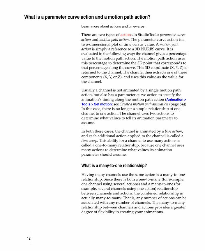
There are two types of actions in StudioTools: parameter curve action and motion path action. The parameter curve action is a two-dimensional plot of time versus value. A motion path action is simply a reference to a 3D NURBS curve. It is evaluated in the following way: the channel gives a percentage value to the motion path action. The motion path action uses this percentage to determine the 3D point that corresponds to that percentage along the curve. This 3D coordinate (X, Y, Z) is returned to the channel. The channel then extracts one of these components (X, Y, or Z), and uses this value as the value for the channel.
Usually a channel is not animated by a single motion path action, but also has a parameter curve action to specify the animation’s timing along the motion path action (Animation > Tools > Set motion; see Create a motion path animation (page 54)). In this case, there is no longer a simple relationship of one channel to one action. The channel uses two actions to determine what values to tell its animation parameter to assume.
In both these cases, the channel is animated by a base action, and each additional action applied to the channel is called a time warp. This ability for a channel to use many actions is called a one-to-many relationship, because one channel uses many actions to determine what values its animation parameter should assume.
What is a many-to-one relationship?
Having many channels use the same action is a many-to-one relationship. Since there is both a one-to-many (for example, one channel using several actions) and a many-to-one (for example, several channels using one action) relationship between channels and actions, the combined relationship is actually many-to-many. That is, any number of actions can be associated with any number of channels. The many-to-many relationship between channels and actions provides a greater degree of flexibility in creating your animations.
12
If a channel uses more than one action, then the channel has an expand channel button next to its name in the Action Window. If you press this button, you see the list of actions that a channel uses.
To see which channels use an action, you can select the action and choose Curve Tools > Show instance in the Action Window.
Summary
The three concepts in the animation system are:
● an animation parameter is an attribute of an item that can be animated.
● a channel is a set of data that describes what values its animation parameter should assume at different frame times.
● an action is a mapping of value versus time.
One-to-many channel to action relationshipX Translate X Translate two actions use the same channel
action #1
action #2
Many-to-one channel to action relationship
Y Translate
one action uses two channelsaction #1
channel
X Translate channel
channel
X Translate
Y Translate
13
In the Action Window, the relationship between an animation parameter and its channel is made implicitly by using the same name for both.
Example
The animation parameter named X Translate is animated by a channel named X Translate. In the Action Window, if an animation parameter is not animated by a channel, the animation parameter name is listed in light grey. If on the other hand, the animation parameter is animated by a channel, then the animation parameter is listed in red (X parameters), green (Y parameters), blue (Z parameters), or black (all others).
See Animation > Editors > Action window, Edit > Edit expression for information on Expres-sions.
Instead of using actions, an animation parameter may be animated by an expression channel. Expressions can be entered by double-clicking next to the animation parameter name in the Timeview Window, or by selecting an animation parameter and choosing Edit > Edit expression from the Action Window.
14
What happens when you animate a camera on a curve?
Learn more about the three camera components: camera eye, camera view, and camera up vector.
Geometry in a scene cannot be animated using the Animation > Tools > Autofly function.
The camera is animated to travel along any NURBS curve.
Camera eyeThe camera eye can be considered the camera unit itself, which travels along the motion path to which it is assigned. The motion path determines the position of the camera at any given time in relation to the scene. For example, the design of the motion path lets you move the camera closer to or further away from an object in the scene. To visualize, think of yourself walking along with a camera taking pictures: the route you follow would be the motion path.
Camera view The camera view can be considered the focus point of the camera — where the camera is looking at any given time. If the camera view is not assigned to a motion path of its own, then the view is always directly in front of the camera. Think of yourself walking through a scene without ever pivoting your head, your view is always directly ahead of your body. By assigning the view to a motion path of its own, you can change the view point of the camera at any time in relation to the camera position.
Camera up vectorThe camera up vector can be considered the current angle of the camera at any given time in relation to the camera eye. The camera up vector is the direction from the camera’s eye to the camera’s up. If the camera’s up is not assigned a motion path of its own, the camera remains parallel to the path that the eye has been assigned to at all times. By assigning the camera up to an independent motion path, the camera can be pivoted to any angle up to 360 degrees. This can be likened to a camera on a tripod except that the tripod could pivot a full 360 degrees.
15
At least one curve is needed to use Autofly. If only one curve is used, it must be the motion path for the camera eye. The camera view then remains directly in front of the camera throughout the animation.This might be exactly what you want. If not, and you want to control the camera view throughout the animation, you need at least two motion path curves.
16
Can I reuse animation on another channel?
Learn how actions are reuseable.
The Action Window has tools to make an action reusable by more than one channel. This means that the actions are not owned by a channel. They can be renamed to any name, independent of any channel with which they may currently be associated. Actions can also be shared by more than one channel (Curve Tools > Paste Instance in the Action Window).
In the example above, imagine you want to use the car’s motion for a bicycle going down the road next to the car. You can use Curve Tools > Paste instance in the Action Window to associate the same action used by the X Translate channel for the car to be used by the X Translate channel of the bicycle as well. Now the car and the bicycle animate together. The advantage of using the same action for both channels is that if you edit the action, then the motion for both vehicles changes.
Example
If you want the car and the bicycle to stop at a house along the way at time 20, and then start moving to the street corner at time 30, you can add two keyframes to the single action, and the animation is modified for both bicycle and car.
17
What is inverse kinematics?
Learn more about the process and workflow of IK animation.
You can create the illusion of life by using the skeleton and inverse kinematics animation tools in StudioTools. The essence of character animation is timing and motion.
Build a skeleton by creating and editing joints and bones. After you’ve created all the joints and bones that make up a skeleton for your character, you’ll want to move the skeleton around and put it in various poses.
There are two basic ways to pose a joint chain: forward kinematics and inverse kinematics.
With forward kinematics, when you pose a joint chain you have a specify the rotations of each joint individually, starting from the parent joint on down to all the joints below.
With inverse kinematics, when you pose a joint chain all you have to do is tell the lowest joint chain’s hierarchy where you want it to be, and all the joints above it will rotate automatically. Inverse kinematics offers a very intuitive way to pose a joint chain because it enables goal-directed posing. When you reach for an object, you don’t think about how you are going to rotate your shoulder, your elbow, and so on. You just think about where the object is that you want to reach, and your body automatically does the rest. That’s how inverse kinematics works, too.
To pose a joint chain with inverse kinematics you need to add some special tools to a skeleton. These tools are called inverse kinematics (IK) handles. An IK handle enables you to pose a joint chain intuitively.
An IK handle begins at a joint chain’s parent joint and can end at any joint below the parent joint. For example, for each leg you could create an IK handle that controls the joint chain beginning at the hip joint and ending at the ankle joint.
You can select the IK handle where it ends at the ankle joint and move the chain with it in the same way that you would think about moving your own ankle.
In addition to posing a skeleton, IK handles also play an important role in the animation of the skeleton. The movement
18
of a chain between the keyframes of an animation is also automatically solved by the chains IK handles.
IK handles figures out how to rotate and move all the joints in the chain for you by applying an inverse kinematics solver. The IK solver is the motor intelligence behind and IK handle.
You can animate a skeleton, but such an animation would show only the timing and motion of a character lacking form and shape. The next step is to bind the character’s model to the character’s skeleton so that the skeleton can control the model’s actions.
Use Animation > IK > New skeleton to create the skeleton, then Animation > IK > Add IK handle, Animation > Tools > Create constraint, and Animation > Keyframe > Set keyframe or Animation > Keyframe > Auto keyframe to animate your character in its rotation scale and translation parameters.
Create hierarchical geometry for the character independently from the animation and use Animation > Editors > Skeletons to turn DAG nodes in the hierarchy into joint DAG nodes. Then use Animation > Edit > Overlay skeleton to overlay the corresponding joint nodes in the model.
19
What is a time warp curve?
Learn how time warp curves work.
A time warp curve is an animation curve (or a action) that is applied to a channel (the animation of a parameter of an item), and modifies the times at which the other actions in the channel are evaluated.
A channel of an item is usually animated by one animation curve, the base action of the channel. If a time warp curve is applied to the channel, then the channel is now animated by two actions. The time warp action modifies how the base action of the channel is evaluated.
You can apply any number of time warp curves to a channel, and each successive time warp curve modifies the timing of the curve directly below it.
How does a time warp work
The time warp curve changes the timing of a channel by mapping the old time of an animation on the Y-axis to the new absolute time on the X-axis. Another way to look at this is that at a given time on the X-axis, the time warp curve is evaluated to a value on the Y-axis, which is a new time. The time is used as the time at which to evaluate the next action in the channel to which the time warp is applied.
Example of a time warp
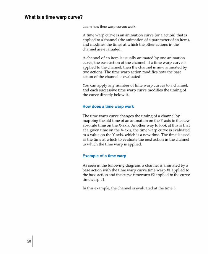
As seen in the following diagram, a channel is animated by a base action with the time warp curve time warp #1 applied to the base action and the curve timewarp #2 applied to the curve timewarp #1.
In this example, the channel is evaluated at the time 5.
20
1 First, evaluate the last action in the channel, which is timewarp #2, at time 5. Notice that it evaluates to 12.
2 Use the new time and evaluate the next curve in the channel, which is timewarp #1 at time 12, and see that it is evaluates to 8.5.
3 Use this new time and evaluate the first and final curves in the channel, which is the base action, and it evaluates to 21. Therefore, the value of the channel at time 5 is 21.
When you create time warps curves, they have a default out-of-range type of identity (from the Action Window’ Disp Tools > show infinity menu). This means that before the first keyframe and after the last keyframe of the time warp curve, the time warp curve does not alter or warp the timing of the actions below it.
If many time warp curves are applied to a channel, it is often difficult to fine-tune special areas of the animation in the channel. When you are satisfied with the general animation of a channel with its time warps, you can use Curve Tools > use result found in the Animation > Editors > Action window > Action Graphic Editor to collapse all the time warps onto the channel’s base action. A single parameter curve action is created that evaluates to the same values as the channel with all its time warps. The channel’s animation is now replaced by the single resulting parameter curve action.
Evaluatedchannel value
5 10 20 308.5 12 15 25
5
10
15
20
21
12
8.5
3
1
2
final value of channel evaluated at time 5time warp #2
base action
time warp #1
0
21

22
How do I?How to preform animation tasks in StudioTools.
23
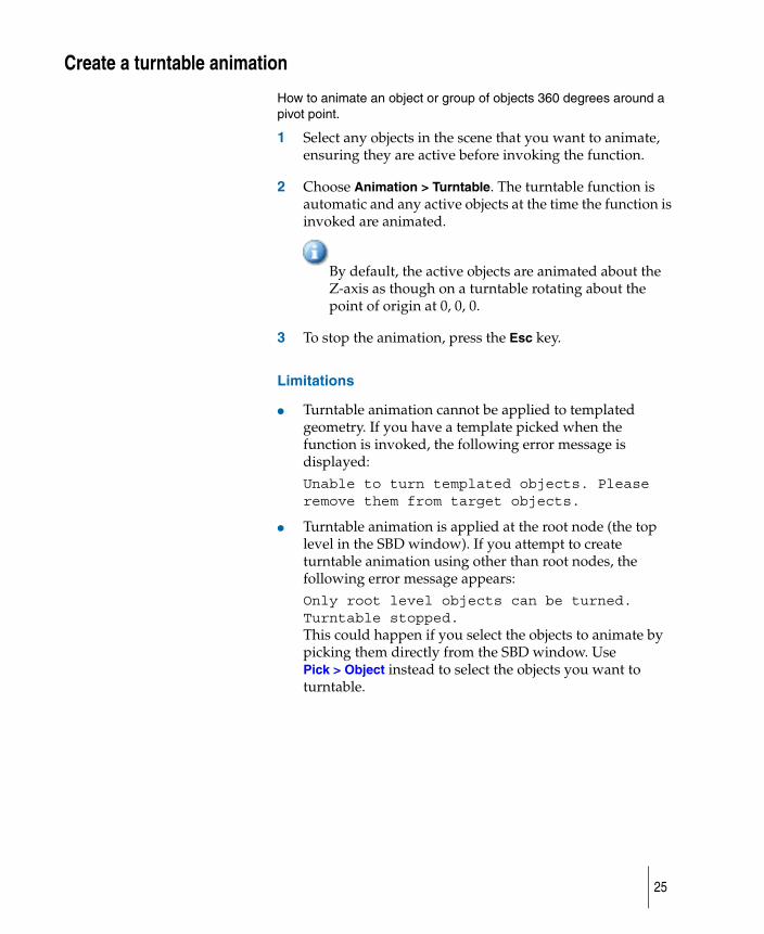
Create a turntable animationHow to animate an object or group of objects 360 degrees around a pivot point.
The camera cannot be animated with this function.
24
Create a turntable animation
How to animate an object or group of objects 360 degrees around a pivot point.
1 Select any objects in the scene that you want to animate, ensuring they are active before invoking the function.
2 Choose Animation > Turntable. The turntable function is automatic and any active objects at the time the function is invoked are animated.
By default, the active objects are animated about the Z-axis as though on a turntable rotating about the point of origin at 0, 0, 0.
3 To stop the animation, press the Esc key.
Limitations
● Turntable animation cannot be applied to templated geometry. If you have a template picked when the function is invoked, the following error message is displayed:Unable to turn templated objects. Please remove them from target objects.
● Turntable animation is applied at the root node (the top level in the SBD window). If you attempt to create turntable animation using other than root nodes, the following error message appears:Only root level objects can be turned. Turntable stopped.This could happen if you select the objects to animate by picking them directly from the SBD window. Use Pick > Object instead to select the objects you want to turntable.
25
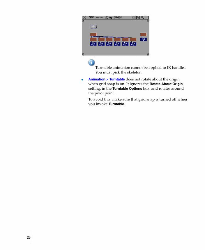
Turntable animation cannot be applied to IK handles. You must pick the skeleton.
● Animation > Turntable does not rotate about the origin when grid snap is on. It ignores the Rotate About Origin setting, in the Turntable Options box, and rotates around the pivot point.
To avoid this, make sure that grid snap is turned off when you invoke Turntable.
26

Create a keyframe animationHow to set keyframes in your animation to objects, lights, shaders, textures, cameras, and other objects.
27
Use keyframes
How to use keyframes animation.
Apply a keyframe to your animation
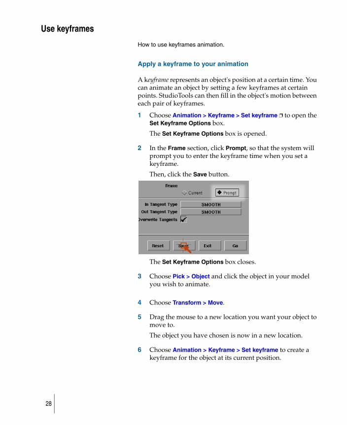
A keyframe represents an object's position at a certain time. You can animate an object by setting a few keyframes at certain points. StudioTools can then fill in the object's motion between each pair of keyframes.
1 Choose Animation > Keyframe > Set keyframe ❐ to open the Set Keyframe Options box.
The Set Keyframe Options box is opened.
2 In the Frame section, click Prompt, so that the system will prompt you to enter the keyframe time when you set a keyframe.
Then, click the Save button.
The Set Keyframe Options box closes.
3 Choose Pick > Object and click the object in your model you wish to animate.
4 Choose Transform > Move.
5 Drag the mouse to a new location you want your object to move to.
The object you have chosen is now in a new location.
6 Choose Animation > Keyframe > Set keyframe to create a keyframe for the object at its current position.
28
7 Then type 0 and press Enter to set the point-in-time for the keyframe to frame zero. This will be the start point of the animation.
8 With the Move tool still active, turn on magnet snap mode again.
9 Drag the mouse to final position to move the object there, then turn off magnet snap mode.
Your object is now snapped to final position in the animation.
10 Choose Animation > Keyframe > Set keyframe to create a keyframe for the sphere at its current position.
11 Type the end time for your animation and press Enter to set the point-in-time for the keyframe.
29
Edit a keyframe animation
How to edit keyframe animation.
animatingMouse2.rm
Edit the animation curve tangents
There will be a number of times when you want to edit your animation to make it more realistic. To show you how this is done we provide an example of editing a sphere in an animation.
First you'll change the sphere's rate of speed at the beginning of the animation by editing its animation curve tangents.
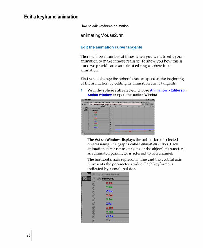
1 With the sphere still selected, choose Animation > Editors > Action window to open the Action Window.
The Action Window displays the animation of selected objects using line graphs called animation curves. Each animation curve represents one of the object's parameters. An animated parameter is referred to as a channel.
The horizontal axis represents time and the vertical axis represents the parameter's value. Each keyframe is indicated by a small red dot.
30
The parameter names are listed along the left side of the window.
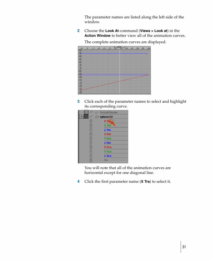
2 Choose the Look At command (Views > Look at) in the Action Window to better view all of the animation curves.
The complete animation curves are displayed.
3 Click each of the parameter names to select and highlight its corresponding curve.
You will note that all of the animation curves are horizontal except for one diagonal line.
4 Click the first parameter name (X Tra) to select it.
31
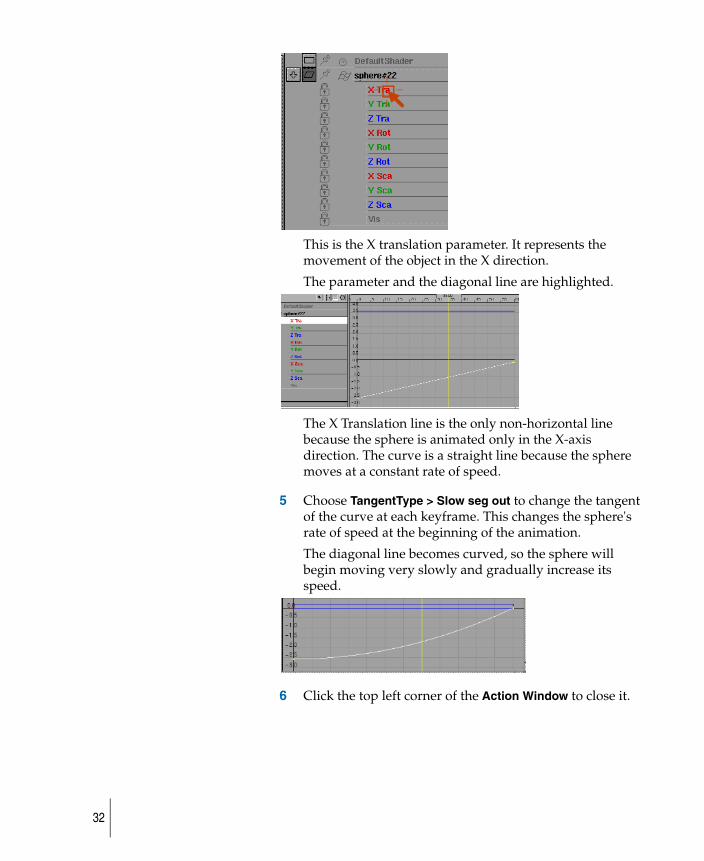
This is the X translation parameter. It represents the movement of the object in the X direction.
The parameter and the diagonal line are highlighted.
The X Translation line is the only non-horizontal line because the sphere is animated only in the X-axis direction. The curve is a straight line because the sphere moves at a constant rate of speed.
5 Choose TangentType > Slow seg out to change the tangent of the curve at each keyframe. This changes the sphere's rate of speed at the beginning of the animation.
The diagonal line becomes curved, so the sphere will begin moving very slowly and gradually increase its speed.
6 Click the top left corner of the Action Window to close it.
32
Playback the animation
How to review your animation.
While the playback is in progress, the current time changes accordingly. The current time is displayed in the current application window, as well as in theAnimation > Show > Toggle time slider and Animation > Editors > Action window. When the animation stops, the current time is the last frame that was viewed during the playback.
To playback the animation
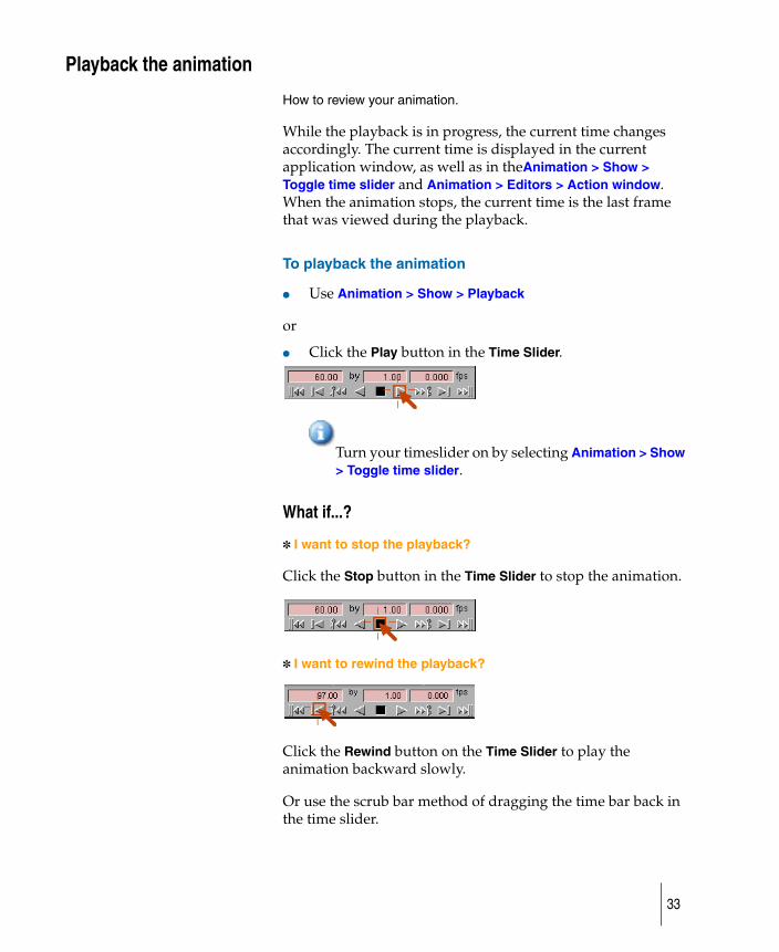
● Use Animation > Show > Playback
or
● Click the Play button in the Time Slider.
Turn your timeslider on by selecting Animation > Show > Toggle time slider.
What if...?
✽ I want to stop the playback?
Click the Stop button in the Time Slider to stop the animation.
✽ I want to rewind the playback?
Click the Rewind button on the Time Slider to play the animation backward slowly.
Or use the scrub bar method of dragging the time bar back in the time slider.
33
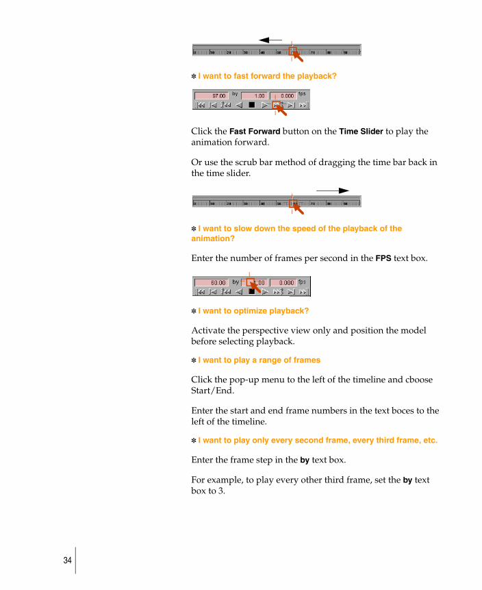
✽ I want to fast forward the playback?
Click the Fast Forward button on the Time Slider to play the animation forward.
Or use the scrub bar method of dragging the time bar back in the time slider.
✽ I want to slow down the speed of the playback of the animation?
Enter the number of frames per second in the FPS text box.
✽ I want to optimize playback?
Activate the perspective view only and position the model before selecting playback.
✽ I want to play a range of frames
Click the pop-up menu to the left of the timeline and cboose Start/End.
Enter the start and end frame numbers in the text boces to the left of the timeline.
✽ I want to play only every second frame, every third frame, etc.
Enter the frame step in the by text box.
For example, to play every other third frame, set the by text box to 3.
34
View individual frames of animation
Learn how to set view frames to walk through a list of key times and see what the key steps look like.
Use View frame to view any number of frames. When viewing more than one frame, there is a short pause between each frame that is displayed.
To set view frames
1 Create an animation using any combination of the animation tools, for example Animation > Keyframe > Set keyframe, Animation > Keyframe > Auto keyframe, or Animation > Editors > Action window, or Animation > Tools > Set motion.
2 To view a frame of the animation, choose Animation > Show > View frame or click its icon. The system prompts you to type the numbers of one or more frames to view (separate a sequence of frame numbers by spaces). The animated items are evaluated and displayed at the frames you specified.
The current time is updated to the last frame that was viewed and is displayed in the current application window, as well as in the Time slider (Animation > Show > Toggle time slider) and the Action Window (Animation > Editors > Action window).
Although this function does not have an option box, it uses the Objects, Parameters, and Hierarchy options from Animation Options in the Playback Options window. (Choose Animation > Editors > Playback options and click the arrow beside Animation Options to display that section of the window.)
Any optimization settings (for example, lights or cameras) specified in Animation > Editors > Playback options are ignored.
35
Preview a rendered animation with FlipBook (UNIX only)
Learn how to preview animations in rendered forms.
FlipBook (available for UNIX systems) lets you preview animation in rendered form, and can display multiple sequences of PIX, SGI, TIFF or TIFF16 files simultaneously or in sequence while maintaining a specified frame rate. It also has advanced compression options.
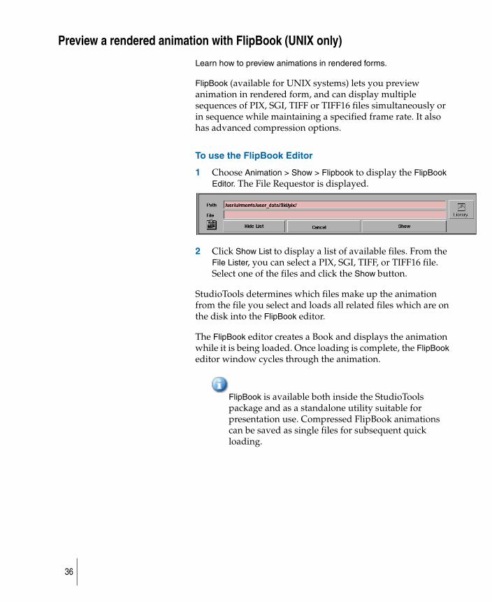
To use the FlipBook Editor
1 Choose Animation > Show > Flipbook to display the FlipBook Editor. The File Requestor is displayed.
2 Click Show List to display a list of available files. From the File Lister, you can select a PIX, SGI, TIFF, or TIFF16 file. Select one of the files and click the Show button.
StudioTools determines which files make up the animation from the file you select and loads all related files which are on the disk into the FlipBook editor.
The FlipBook editor creates a Book and displays the animation while it is being loaded. Once loading is complete, the FlipBook editor window cycles through the animation.
FlipBook is available both inside the StudioTools package and as a standalone utility suitable for presentation use. Compressed FlipBook animations can be saved as single files for subsequent quick loading.
36
View images with fcheck (Windows only)
In Windows, use Animation > Show > FCheck to do the following:
● display a single image or a sequence of images
● display the intermediate results of a rendering in progress
● do color correction and image editing, including luminance, gamma, and bump values
● display looping animations – ones that play over and over
● view images that are in a variety of image formats
● play sounds that go with an animation
To use FCheck
1 Choose Animation > Show > FCheck to start this utility. For further information on its use, choose an item from the Help menu on the FCheck window bar.
37
Use Auto keyframe
How to set keysframes automatically.
Auto keyframe automatically sets keyframes in channels for animation parameters that have changed value since the last time a keyframe was set.
No keyframes are created for any animation parameters that were not previously animated.
To use auto keyframes
1 Create an object, and then choose Animation > Keyframe > Set keyframe to create channels for the object.
2 Scale or rotate the object and choose Auto keyframe.
Keyframes are set for the animation parameters of the object that have been changed by the Transform. For example, if the object was only transformed using Transform > Rotate, keyframes are created for the rotate parameters, but not the translate or scale parameters.
This function operates on a per-channel basis, and not on the picklist or hierarchy. This means that you can transform an object, pick another object, transform that object, and repeat this process for as many objects, shaders or any other animatable objects as you like. When Auto keyframe is invoked, it looks at all channels that have changed, regardless of which object is currently picked, and sets keyframes for those channels.
If the current time changes (for instance, if you choose Animation > Show > View frame, Animation > Show > Playback, or change the current time in the Action Window or Time slider), and the channel is evaluated, then a keyframe is not created for that channel the next time you invoke Auto keyframe.
38
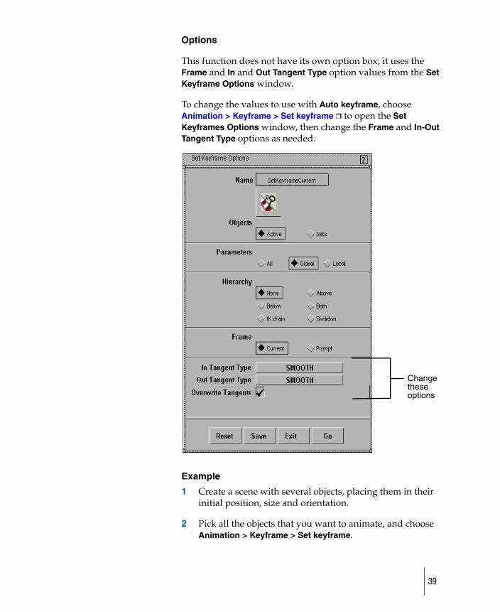
Options
This function does not have its own option box; it uses the Frame and In and Out Tangent Type option values from the Set Keyframe Options window.
To change the values to use with Auto keyframe, choose Animation > Keyframe > Set keyframe ❒ to open the Set Keyframes Options window, then change the Frame and In-Out Tangent Type options as needed.
Example
1 Create a scene with several objects, placing them in their initial position, size and orientation.
2 Pick all the objects that you want to animate, and choose Animation > Keyframe > Set keyframe.
these options
Change
39

3 Move each of the objects to the next snapshot time, choose Auto keyframe, and enter the new keyframe time.
40
Create different segments of your animation
How to use Animation > Tools > Set motion to create several different segments of an animation.
For example, you can do the following:
● animate an object along a NURBS curve. The curve acts as a motion path for the object assigned to it.
● animate an object so that it always points in the direction in which it is traveling, maintaining its original orientation to the path curve at all times as it travels along the path.
● animate an object so that it banks around curves.
● compute the animation for the UP point of a camera.
● animate an object so that it flows or deforms through the animation, bending and twisting as necessary to conform to the shape of the path curve.
● Having an object bend as it travels along a path solves a problem of rigid body animation, which lacks the squashing and stretching that characterizes realistic and believable characters.
41
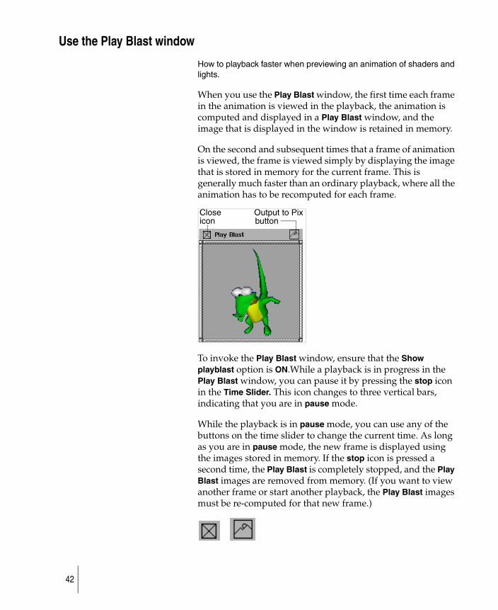
Use the Play Blast window
How to playback faster when previewing an animation of shaders and lights.
When you use the Play Blast window, the first time each frame in the animation is viewed in the playback, the animation is computed and displayed in a Play Blast window, and the image that is displayed in the window is retained in memory.
On the second and subsequent times that a frame of animation is viewed, the frame is viewed simply by displaying the image that is stored in memory for the current frame. This is generally much faster than an ordinary playback, where all the animation has to be recomputed for each frame.
To invoke the Play Blast window, ensure that the Show playblast option is ON.While a playback is in progress in the Play Blast window, you can pause it by pressing the stop icon in the Time Slider. This icon changes to three vertical bars, indicating that you are in pause mode.
While the playback is in pause mode, you can use any of the buttons on the time slider to change the current time. As long as you are in pause mode, the new frame is displayed using the images stored in memory. If the stop icon is pressed a second time, the Play Blast is completely stopped, and the Play Blast images are removed from memory. (If you want to view another frame or start another playback, the Play Blast images must be re-computed for that new frame.)
Close Output to Pix icon button
42
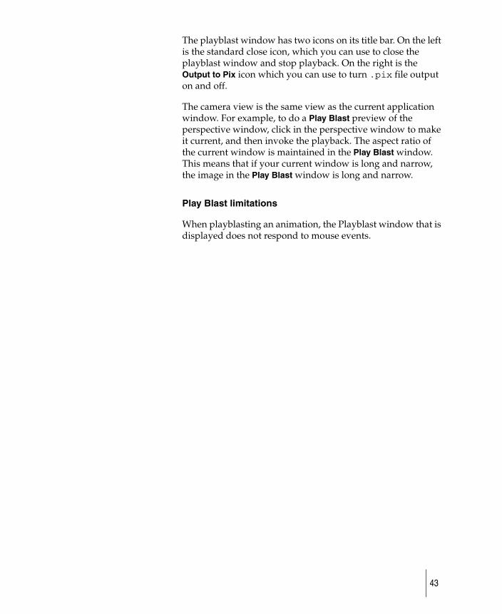
The playblast window has two icons on its title bar. On the left is the standard close icon, which you can use to close the playblast window and stop playback. On the right is the Output to Pix icon which you can use to turn .pix file output on and off.
The camera view is the same view as the current application window. For example, to do a Play Blast preview of the perspective window, click in the perspective window to make it current, and then invoke the playback. The aspect ratio of the current window is maintained in the Play Blast window. This means that if your current window is long and narrow, the image in the Play Blast window is long and narrow.
Play Blast limitations
When playblasting an animation, the Playblast window that is displayed does not respond to mouse events.
43
Edit the animation curve
How to edit animation curves and smooth out the motion or apply abrupt changes at each point in your animation to emphase the movement of your model.
Edit the animation curve
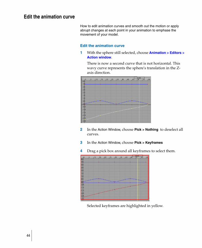
1 With the sphere still selected, choose Animation > Editors > Action window.
There is now a second curve that is not horizontal. This wavy curve represents the sphere's translation in the Z-axis direction.
2 In the Action Window, choose Pick > Nothing to deselect all curves.
3 In the Action Window, choose Pick > Keyframes
4 Drag a pick box around all keyframes to select them.
Selected keyframes are highlighted in yellow.
44
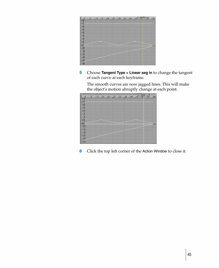
5 Choose Tangent Type > Linear seg in to change the tangent of each curve at each keyframe.
The smooth curves are now jagged lines. This will make the object's motion abruptly change at each point.
6 Click the top left corner of the Action Window to close it.
45
Move keyframes on an animation curve
How to move keyframes on the animation curve.
To move keyframes
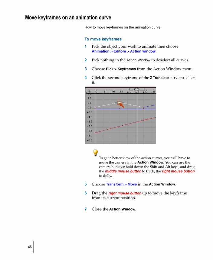
1 Pick the object your wish to animate then choose Animation > Editors > Action window.
2 Pick nothing in the Action Window to deselect all curves.
3 Choose Pick > Keyframes from the Action Window menu.
4 Click the second keyframe of the Z Translate curve to select it.
To get a better view of the action curves, you will have to move the camera in the Action Window. You can use the camera hotkeys: hold down the Shift and Alt keys, and drag the middle mouse button to track, the right mouse button to dolly.
5 Choose Transform > Move in the Action Window.
6 Drag the right mouse button up to move the keyframe from its current position.
7 Close the Action Window.
46
Create SGI and Apple format movie files (IRIX only)
Learn how to display, edit, or create animation movie files in SGI MoviePlayer format or Apple QuickTime format.
This function is for IRIX only.
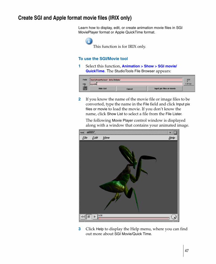
To use the SGI/Movie tool
1 Select this function, Animation > Show > SGI movie/QuickTime. The StudioTools File Browser appears:
2 If you know the name of the movie file or image files to be converted, type the name in the File field and click Input pix files or movie to load the movie. If you don’t know the name, click Show List to select a file from the File Lister.
The following Movie Player control window is displayed along with a window that contains your animated image.
3 Click Help to display the Help menu, where you can find out more about SGI Movie/Quick Time.
47
Add keyframes
How to add additional keyframes to your animation.
To add keyframes to your animation
By adding more keyframes you will gain detailed control over the movement of the model.
1 Choose Transform > Move to move the object to a new location.
2 Choose Animation > Keyframe > Set keyframe to create a keyframe for the object at its current position. Then type a time and press Enter to set the keyframe to frame that time.
3 Continue to move and set new times for each keyframe as you see necessary.
What if...?
✽ I want to watch my animation?
Choose Animation > Show > Playback.
48
Copy keyframes
How to copy animation channels for other animations.
Use Animation > Keyframe > Copy keyframe to copy a range of keyframes from an animated object, and place them on the keyframe clipboard for pasting somewhere else.
When you are working with animated sequences, it is often necessary to copy a sequence from one object to another, or to repeat a sequence. Copy keyframes and Paste keyframes provide a simple way to do this.
Copy keyframes lets you select an object and specify a range of keyframes from the object’s animations to copy. The selected keyframes are then copied to a keyframe clipboard, which lets you mirror or paste the keyframes onto another object (or even back onto itself).
To copy keyframes into your animation
1 Pick an animated object and choose Animation > Keyframe > Copy keyframe.
This operation overwrites any other keyframes that may already have been placed on the keyframe clipboard.
The system prompts:Enter the frame range to copy (start, end):
2 To copy the animation between frame 30 and 60, for example, type:30 60
To copy a single frame, type the same frame number for both the start and end frame.
3 Choose Animation > Keyframe > Paste keyframe
49
What if...?
✽ I want to paste the animation somewhere else.
See Paste keyframes on page 53.
50
Cut keyframes
How to remove a range of keyframes from a selected object.
When you are working with animated sequences, it is often necessary to change the order in which events occur or to remove sequences altogether. Cutting or copying keyframes, and then pasting them, provides a simple way to do this.
Cut keyframes lets you select an object (or group of objects) and remove a range of keyframes from their animations. You can also specify whether the remaining animation is to be compressed (pulled back in time) or to be left alone. Additionally, if only a single object is selected, the keyframes that are removed are copied to a keyframe clipboard, which lets you paste those keyframes onto another object (or even back onto itself).
● if more than one object is picked, all of their keyframes will be removed; however, none of the keyframes will be copied to the keyframe clipboard.
● if a single object is picked, its keyframes will overwrite any other keyframes that may already have been placed on the keyframe clipboard.
To cut keyframes from your animation
1 Pick an animated object and choose Animation > Keyframe > Cut keyframe.
The system prompts:Enter the frame range to cut (start, end):
2 To cut the animation between frame 30 and 60, for example, type:30 60
To remove just one frame, type the same frame number for both the start and end frame.
3 Choose Animation > Keyframe > Paste keyframe to paste the animation somewhere else.
51
To use this technique on channels that are animated by constraints, IK, or expressions, first convert them to keyframes animation. Use the Bake plug-in for constraints and expressions, and Run IK for IK animation.
52
Paste keyframes
How to specify the sequence of keyframes to be repeated a number of times.
Use Animation > Keyframe > Paste keyframe to paste a range of copied keyframes from the clipboard (using either Cut keyframes or Copy keyframes) onto an object. The keyframes can be pasted into different animatable channels and on objects other than the source.
When you are working with animated sequences, it is often useful to be able to copy a sequence from one object to another, or to repeat a sequence. Cutting or copying keyframes, and then pasting them, provides a simple way to do this.
Animation > Keyframe > Paste keyframe lets you specify the sequence to be repeated any number of times. You can also specify what should be done to any existing animation. (For example, you can write the new sequence over an existing sequence or insert it into an existing sequence.)
To paste keyframes in your animation
1 Pick an animated object and choose Animation > Keyframe > Cut keyframe or Copy.
See Cut keyframes (page 51) and Copy keyframes (page 49).
2 Pick another object (or the same object) and choose Animation > Keyframe > Paste keyframe.
You can copy a range of keyframes from one hierarchical object to another, even if the two objects do not share the exact same topology. The ordering of nodes in the SBD window is used to match up nodes from the source object with those of the destination object(s). Only nodes that have the same relative SBD position and node type are matched.
53
3 The system prompts:Enter the frame range to paste (start, [repeats], [gap], [end]):
If Range fit is set to None and an ending frame is specified, Scale paste is performed.
Paste the animation by typing the values prompted for. The following examples illustrate various situations.
◆ To paste an animation sequence at frame 30, type: 30
◆ To paste an animation sequence to fit between frames 30 and 75, type: 30 1 1 75
◆ To paste the animation sequence 3 times, starting at frame 30, type: 30 3
◆ To paste an animation sequence 3 times and make it fit between frames 30 and 75, type: 30 3 1 75
◆ To paste an animation sequence 3 times, starting at frame 30, with a space of 5 frames between each sequence, type: 30 3 5
Create a motion path animation
How to create an animation which follows along the path of a curve.
This is a helpful tool to use when giving a final presentation of a model.
animatingMouse3.rm
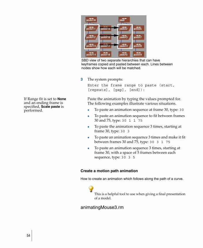
SBD view of two separate hierarchies that can have keyframes copied and pasted between each. Lines between nodes show how each will be matched.
54
Animate objects along a motion path
How to use a curve as your motion path.
To create a motion path animation
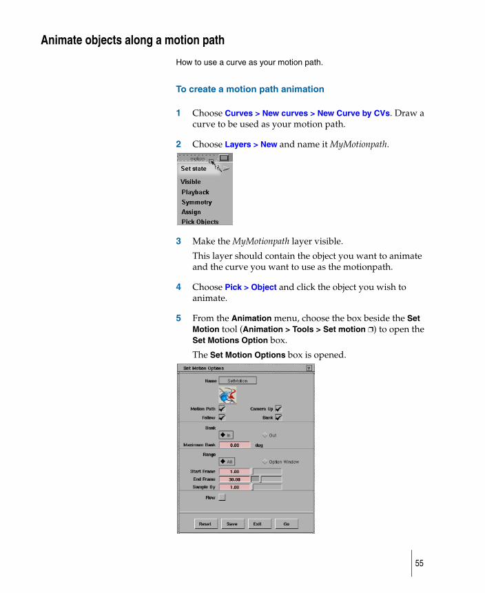
1 Choose Curves > New curves > New Curve by CVs. Draw a curve to be used as your motion path.
2 Choose Layers > New and name it MyMotionpath.
3 Make the MyMotionpath layer visible.
This layer should contain the object you want to animate and the curve you want to use as the motionpath.
4 Choose Pick > Object and click the object you wish to animate.
5 From the Animation menu, choose the box beside the Set Motion tool (Animation > Tools > Set motion ❐) to open the Set Motions Option box.
The Set Motion Options box is opened.
55
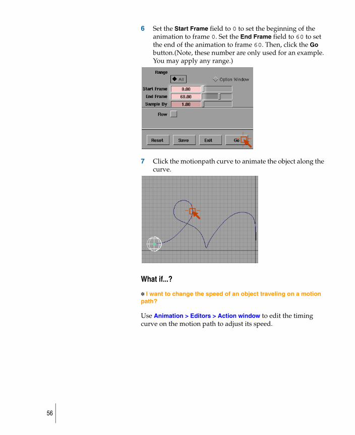
6 Set the Start Frame field to 0 to set the beginning of the animation to frame 0. Set the End Frame field to 60 to set the end of the animation to frame 60. Then, click the Go button.(Note, these number are only used for an example. You may apply any range.)
7 Click the motionpath curve to animate the object along the curve.
What if...?
✽ I want to change the speed of an object traveling on a motion path?
Use Animation > Editors > Action window to edit the timing curve on the motion path to adjust its speed.
56
Set up a camera to travel along a motion path
Allows you to animate the camera view of a scene along a path to effectively simulate a walkthrough of a scene.
1 Choose Animation > Tools > Autofly (If you want to specify options such as start and end frames, choose Autofly ❒.)
The following prompt is displayed:Select the motion path for the camera EYE to follow
Objects do not have to be active when this function is invoked.
2 Click the curve you want to assign as the motion path for the camera eye. The curve will change color to indicate that it is now a motion path.
Once the camera eye motion path has been selected, the system prompts:Select the motion path for the VIEW, or select the GO icon
3 To use a second curve for the camera view, click the curve that you want to assign as the motion path of the camera view.
If you click the Go icon instead, the system uses a camera view motion path that is straight ahead along the motion path chosen for the camera eye.
4 Once you select the camera view motion path and clicked the Go icon, the system prompts:Select the motion path for the UP, or select the GO icon
To use a third curve for the camera up, click directly on the curve you want to assign as the camera up path.
If you click the Go icon instead, the system generates the camera up motion path. The camera is oriented in the up direction, and banks around curves according to the current Maximum Bank degree values set in the Autofly Options box.
5 When you are finished selecting curves, a new perspective window is created and its camera is animated along the curves.
57
Motion paths are invisible during the animation.
6 To halt the animation playback, press the Esc key.
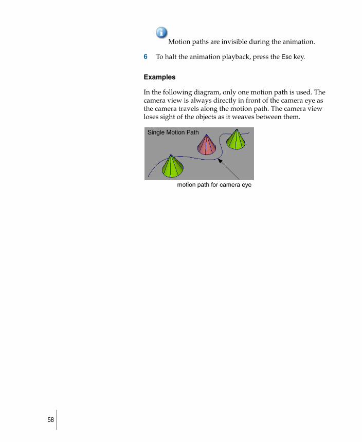
Examples
In the following diagram, only one motion path is used. The camera view is always directly in front of the camera eye as the camera travels along the motion path. The camera view loses sight of the objects as it weaves between them.
motion path for camera eye
Single Motion Path
58
Edit the timing curve of a motion path
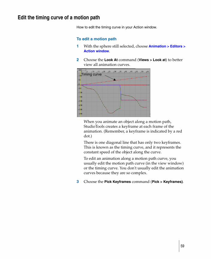
How to edit the timing curve in your Action window.
To edit a motion path
1 With the sphere still selected, choose Animation > Editors > Action window.
2 Choose the Look At command (Views > Look at) to better view all animation curves.
When you animate an object along a motion path, StudioTools creates a keyframe at each frame of the animation. (Remember, a keyframe is indicated by a red dot.)
There is one diagonal line that has only two keyframes. This is known as the timing curve, and it represents the constant speed of the object along the curve.
To edit an animation along a motion path curve, you usually edit the motion path curve (in the view window) or the timing curve. You don't usually edit the animation curves because they are so complex.
3 Choose the Pick Keyframes command (Pick > Keyframes).
Timing curve
59
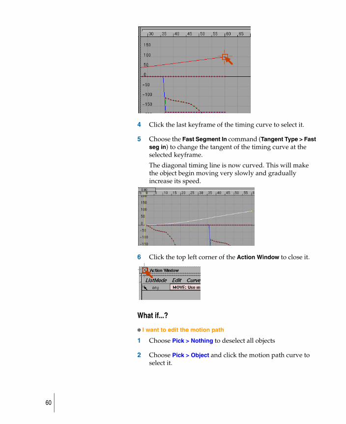
4 Click the last keyframe of the timing curve to select it.
5 Choose the Fast Segment In command (Tangent Type > Fast seg in) to change the tangent of the timing curve at the selected keyframe.
The diagonal timing line is now curved. This will make the object begin moving very slowly and gradually increase its speed.
6 Click the top left corner of the Action Window to close it.
What if...?
✽ I want to edit the motion path
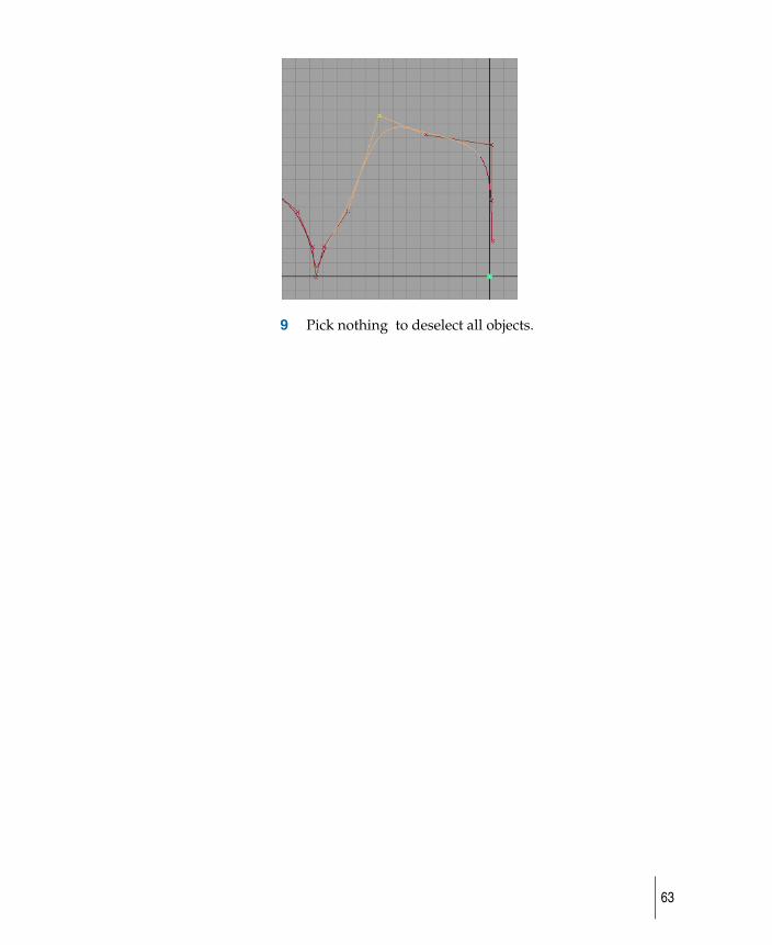
1 Choose Pick > Nothing to deselect all objects
2 Choose Pick > Object and click the motion path curve to select it.
60
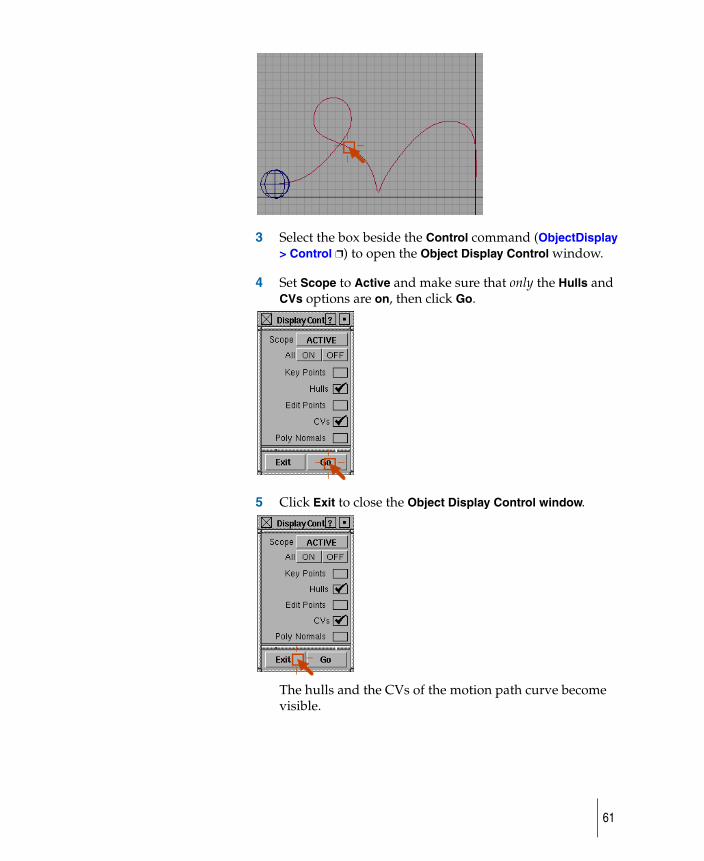
3 Select the box beside the Control command (ObjectDisplay > Control ❐) to open the Object Display Control window.
4 Set Scope to Active and make sure that only the Hulls and CVs options are on, then click Go.
5 Click Exit to close the Object Display Control window.
The hulls and the CVs of the motion path curve become visible.
61
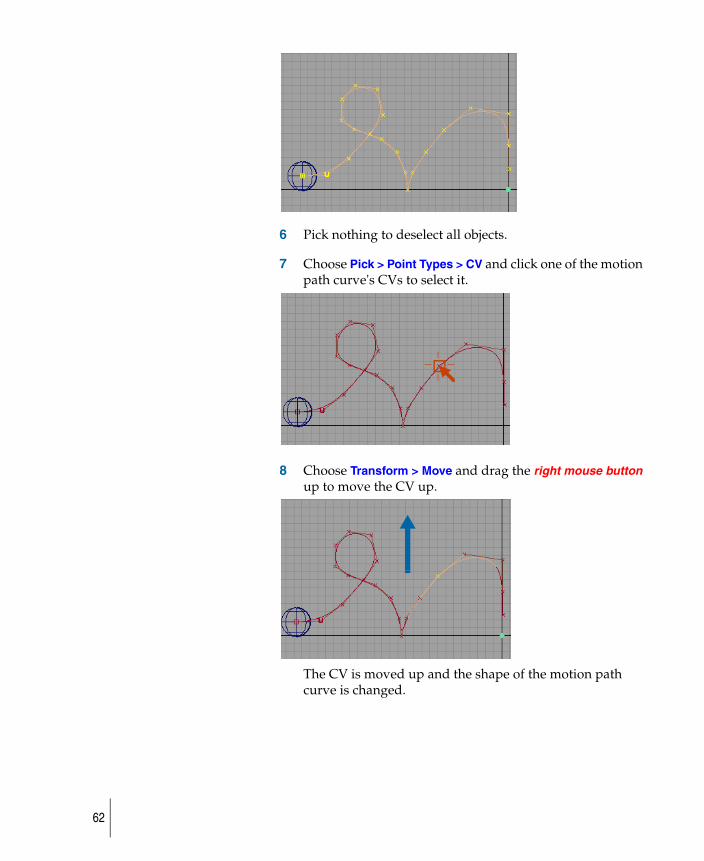
6 Pick nothing to deselect all objects.
7 Choose Pick > Point Types > CV and click one of the motion path curve's CVs to select it.
8 Choose Transform > Move and drag the right mouse button up to move the CV up.
The CV is moved up and the shape of the motion path curve is changed.
62
9 Pick nothing to deselect all objects.
63
Animate a camera on a motion path
How to set a camera in your animated scene.
Use the Camera icon to select the views’s camera. You can animate the view of the scene by creating keyframes for the view's camera. You can also animate a camera using motion paths.
To add a camera view to a motion path
animatingMouse4.rm
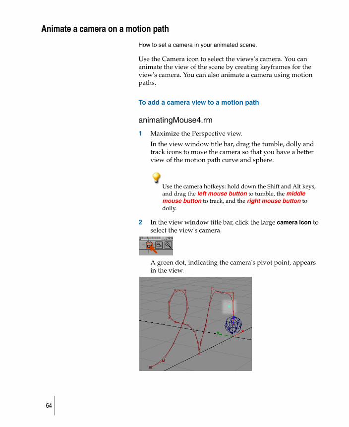
1 Maximize the Perspective view.
In the view window title bar, drag the tumble, dolly and track icons to move the camera so that you have a better view of the motion path curve and sphere.
Use the camera hotkeys: hold down the Shift and Alt keys, and drag the left mouse button to tumble, the middle mouse button to track, and the right mouse button to dolly.
2 In the view window title bar, click the large camera icon to select the view's camera.
A green dot, indicating the camera's pivot point, appears in the view.
64
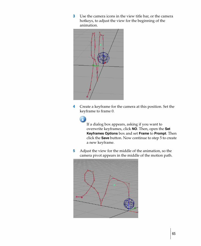
3 Use the camera icons in the view title bar, or the camera hotkeys, to adjust the view for the beginning of the animation.
4 Create a keyframe for the camera at this position. Set the keyframe to frame 0.
If a dialog box appears, asking if you want to overwrite keyframes, click NO. Then, open the Set Keyframes Options box and set Frame to Prompt. Then click the Save button. Now continue to step 5 to create a new keyframe.
5 Adjust the view for the middle of the animation, so the camera pivot appears in the middle of the motion path.
65
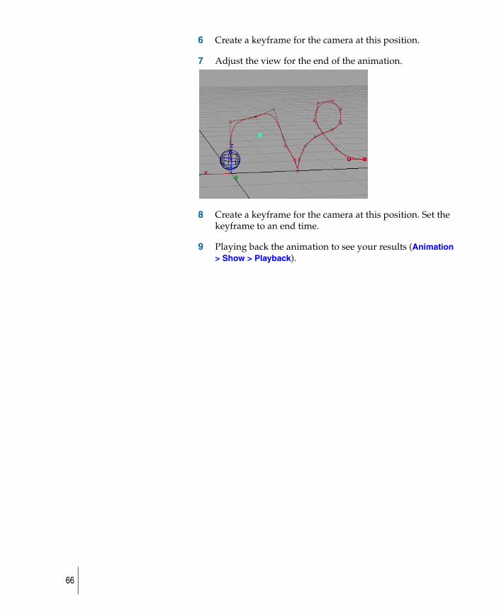
6 Create a keyframe for the camera at this position.
7 Adjust the view for the end of the animation.
8 Create a keyframe for the camera at this position. Set the keyframe to an end time.
9 Playing back the animation to see your results (Animation > Show > Playback).
66
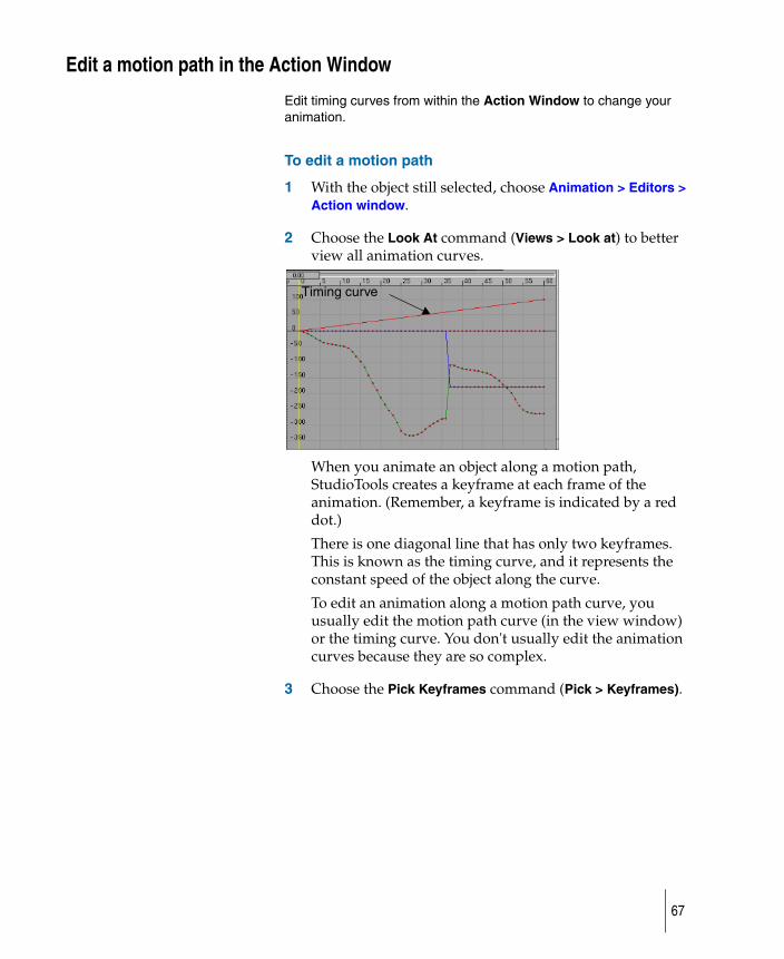
Edit a motion path in the Action Window
Edit timing curves from within the Action Window to change your animation.
To edit a motion path
1 With the object still selected, choose Animation > Editors > Action window.
2 Choose the Look At command (Views > Look at) to better view all animation curves.
When you animate an object along a motion path, StudioTools creates a keyframe at each frame of the animation. (Remember, a keyframe is indicated by a red dot.)
There is one diagonal line that has only two keyframes. This is known as the timing curve, and it represents the constant speed of the object along the curve.
To edit an animation along a motion path curve, you usually edit the motion path curve (in the view window) or the timing curve. You don't usually edit the animation curves because they are so complex.
3 Choose the Pick Keyframes command (Pick > Keyframes).
Timing curve
67
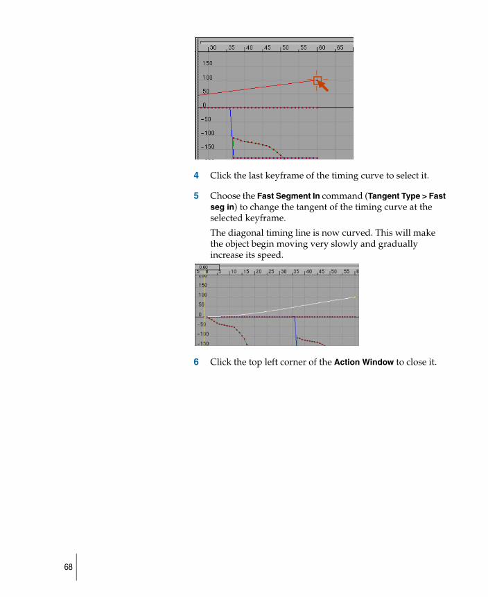
4 Click the last keyframe of the timing curve to select it.
5 Choose the Fast Segment In command (Tangent Type > Fast seg in) to change the tangent of the timing curve at the selected keyframe.
The diagonal timing line is now curved. This will make the object begin moving very slowly and gradually increase its speed.
6 Click the top left corner of the Action Window to close it.
68

Delete the animation for the object
Delete animated channels from an object.
1 Pick the object you have applied the animation to.
2 Choose Delete > Animation > Delete channels.
3 A confirmation box appears asking if you want to delete all animation from all objects. To delete the selected animation, click YES, or type the letter y. (No action is taken if you click NO or type the letter n.)
69

70
Create an exploded view animationHow to animate the assembly of components of your model.
71
Create an exploded view animation
How to create an exploded view animation.
After your model has been created you can apply keyframes to positions of each of the main parts to display the order of assembly of the final model.
An animation that shows all parts of an assembly arranging themselves to form the object. The best way to accomplish this type of animation is to start at the end with the assembled model and develop the animation backwards.
To explain this concept we have used an example of assembling a computer mouse where it first appears assembled, then being assembled, and finally fully unassembled.
When creating your model separate the main components and Assign them to separate layers.
To set the final keyframe
We are assuming that you have a completed model.
1 Create a new layer and name it cameraview
2 Verify that nothing is animated on your model by clicking the Play button on your timeslider.
3 Choose Pick > Object and drag a pick box around the entire model to select all of its components.
4 Choose Animation > Keyframe > Set keyframe and create a keyframe for each models component at its current position. Set the keyframe for frame final time.
5 In the Time Slider, click the Start/End button (located at the left end of the Time Slider).
6 Choose Min/Max from the menu.
72
To set the initial keyframe
1 Pick nothing to deselect all objects.
2 Choose Pick > Object and pick a component of your model you wish to animate first.
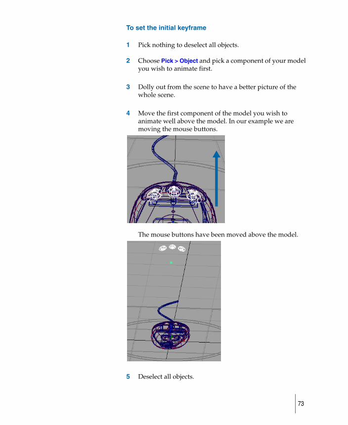
3 Dolly out from the scene to have a better picture of the whole scene.
4 Move the first component of the model you wish to animate well above the model. In our example we are moving the mouse buttons.
The mouse buttons have been moved above the model.
5 Deselect all objects.
73
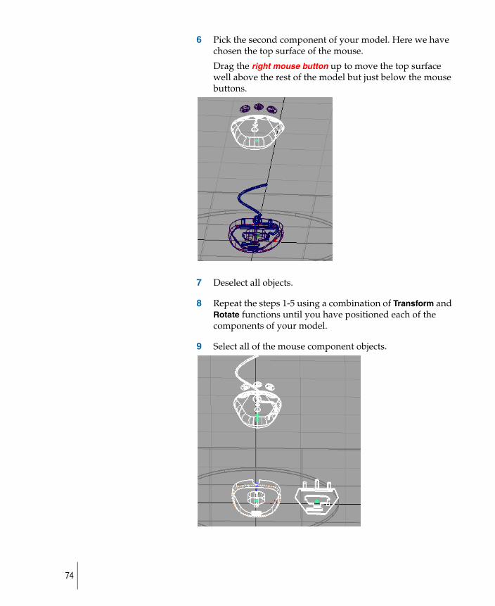
6 Pick the second component of your model. Here we have chosen the top surface of the mouse.
Drag the right mouse button up to move the top surface well above the rest of the model but just below the mouse buttons.
7 Deselect all objects.
8 Repeat the steps 1-5 using a combination of Transform and Rotate functions until you have positioned each of the components of your model.
9 Select all of the mouse component objects.
74
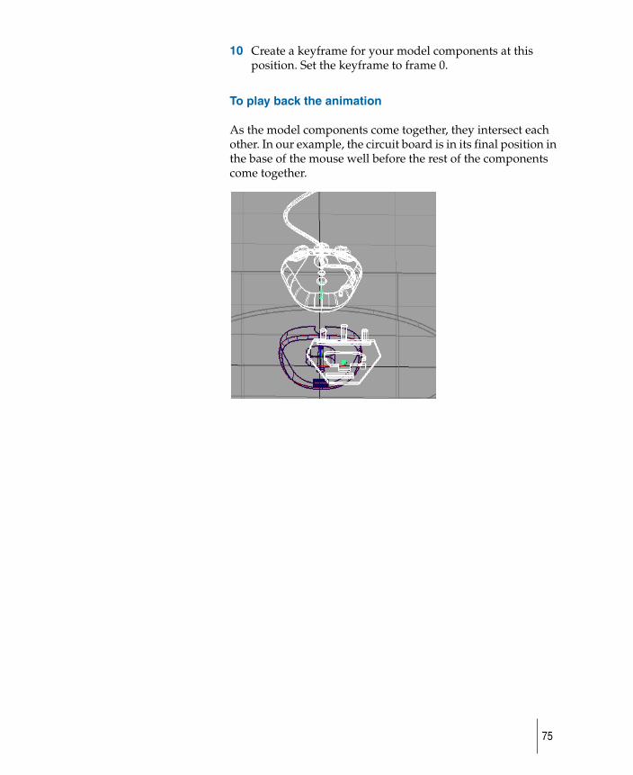
10 Create a keyframe for your model components at this position. Set the keyframe to frame 0.
To play back the animation
As the model components come together, they intersect each other. In our example, the circuit board is in its final position in the base of the mouse well before the rest of the components come together.
75
Prevent collisions in your exploded view animation
How to prevents objects in you animation from colliding into each other.
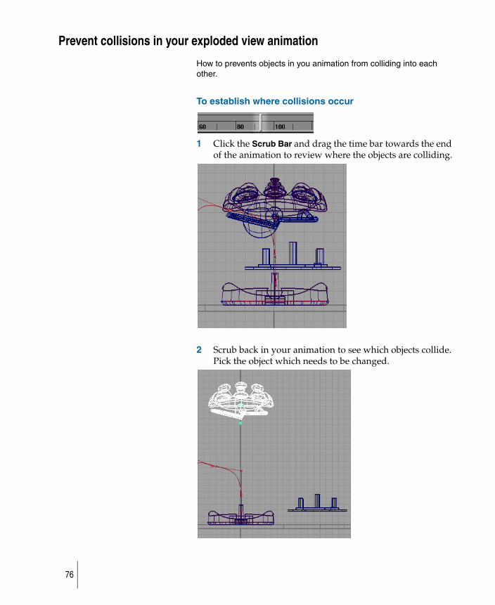
To establish where collisions occur
1 Click the Scrub Bar and drag the time bar towards the end of the animation to review where the objects are colliding.
2 Scrub back in your animation to see which objects collide. Pick the object which needs to be changed.
76
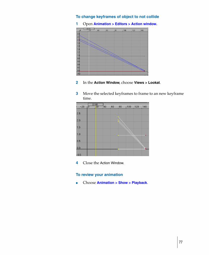
To change keyframes of object to not collide
1 Open Animation > Editors > Action window.
2 In the Action Window, choose Views > Lookat.
3 Move the selected keyframes to frame to an new keyframe time.
4 Close the Action Window.
To review your animation
● Choose Animation > Show > Playback.
77

78

Prepare to import or exportHow to examine DAG node information before exporting or importing.
79
Preview an animation without reducing the scene
How to view an animation in shaded mode.
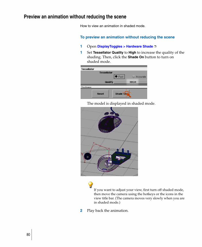
To preview an animation without reducing the scene
1 Open DisplayToggles > Hardware Shade ❐
1 Set Tessellator Quality to High to increase the quality of the shading. Then, click the Shade On button to turn on shaded mode.
The model is displayed in shaded mode.
If you want to adjust your view, first turn off shaded mode, then move the camera using the hotkeys or the icons in the view title bar. (The camera moves very slowly when you are in shaded mode.)
2 Play back the animation.
80
3 Choose DisplayToggles > Hardware Shade to turn off shaded mode.
81
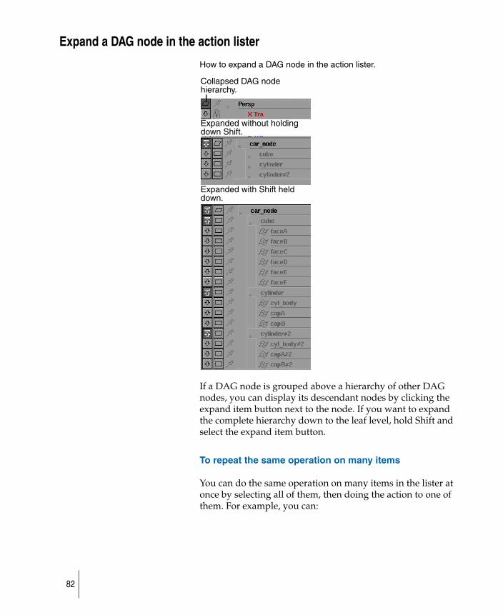
Expand a DAG node in the action lister
How to expand a DAG node in the action lister.
If a DAG node is grouped above a hierarchy of other DAG nodes, you can display its descendant nodes by clicking the expand item button next to the node. If you want to expand the complete hierarchy down to the leaf level, hold Shift and select the expand item button.
To repeat the same operation on many items
You can do the same operation on many items in the lister at once by selecting all of them, then doing the action to one of them. For example, you can:
Collapsed DAG nodehierarchy.
Expanded without holdingdown Shift.
Expanded with Shift helddown.
82
1 Select several items in the list
2 Select the Expand channels button of one of the items to expand the channels of all the selected items.
To change the name of an item
To change the name of a DAG node, camera, shader, or other item in the lister.
1 Double-click the item.
2 Use the Esc key to clear the field of its name, and type a new name.
Names of actions can also be changed in this way.
To switch a pick function while in the Action window
When you are in any function in the Action window, you can temporarily enter the Pick > function by holding down the Shift key. For example, if you have selected Transform > Move in the Action Window, hold down the Shift key and click some keyframes to select or deselect them, then release the Shift key and continue with your Transform > Move operation.
You can also use a box to pick Action Window elements. For example, if you are in Transform > Randomize in the Action Window, and you want to change the selection of keyframes to be randomized, hold down the Shift key and drag a box around picked keyframes to unpick them, or new keyframes to pick, then randomize.
To use the Character Builder
For Animation > Editors > Deformation control, if you choose CHARACTER BUILDER from the Frame Type menu and toggle Bulging ON, you can edit the bulge definitions in the Bulge Section Editor.
To add new sections
When editing in either the Bulge Selection Editor or Section Editor, you can add new sections or key points by holding the Shift key and clicking and dragging to a new position.
83
To delete sections
You can delete sections or key points by holding down the Alt key and clicking and dragging to the section or key point you want to delete.
84
Export animation channels
How to export the animation channels from your model to use in other models.
You can save segments of your animation by objects, hierarchies, or scenes, and apply them to another model or scene
To export animation channels from your model
1 Select the object which you have animation applied to.
2 Choose File > Export > Anim ❐
3 Save the SDL file.
85
Import animation
How to import animation channels from other models.
To import animation channels into your model
1 Select the object which you have animation applied to.
2 Choose File > Export > Anim ❐
86
Create skeletons and inverse kinematics animationHow to draw a skeleton animation.
87
Overview on skeletons
Skeletons enable you to create complete character animation sequences before you have to create any of the geometry for the character.
Use Animation > IK > New skeleton to create the skeleton, then Animation > IK > Add IK handle, Animation > Tools > Create constraint, and Animation > Keyframe > Set keyframe or Animation > Keyframe > Auto keyframe to animate your character in its rotation and translation parameters.
You can create the hierarchical geometry for the character independently from the animation, and you can use Animation > Editors > Skeletons to turn DAG nodes in this hierarchy into joint DAG nodes. You can then use Animation > Edit > Overlay skeleton to overlay the animation and other skeleton attributes onto the corresponding joint nodes in the model.
To duplicate a skeleton
1 Create a skeleton using Animation > IK > New skeleton. Animate the skeleton using inverse kinematics (use Animation > IK > Add IK handle) or any of the standard animation tools.
2 Create another skeleton with Animation > IK > New skeleton, or use the Skeleton editor (Animation > Editors > Skeletons) on an existing model that has the same skeleton topology as the first skeleton.
3 Choose Animation > Edit > Overlay skeleton. The system prompts:Select the root of the skeleton that is to be copied.
4 Pick the skeleton to copy by selecting the joint node that defines the root of the skeleton. You can pick this joint from the SBD window or select a joint in the modeling window.
Choose Animation > Tools > Bone style ❒ to specify bone style.
The following illustrations demonstrate the various bone styles.
88
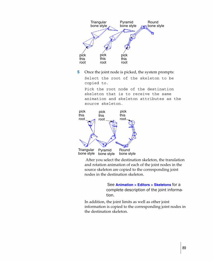
5 Once the joint node is picked, the system prompts: Select the root of the skeleton to be copied to.
Pick the root node of the destination skeleton that is to receive the same animation and skeleton attributes as the source skeleton.
After you select the destination skeleton, the translation and rotation animation of each of the joint nodes in the source skeleton are copied to the corresponding joint nodes in the destination skeleton.
See Animation > Editors > Skeletons for a complete description of the joint informa-tion.
In addition, the joint limits as well as other joint information is copied to the corresponding joint nodes in the destination skeleton.
Triangular
pick
Round
pick
Pyramid bone style bone style bone style
this root
this root
pick this root
Triangular
pickthis root
pickthis root
pickthis root
Pyramid Round bone stylebone stylebone style
89
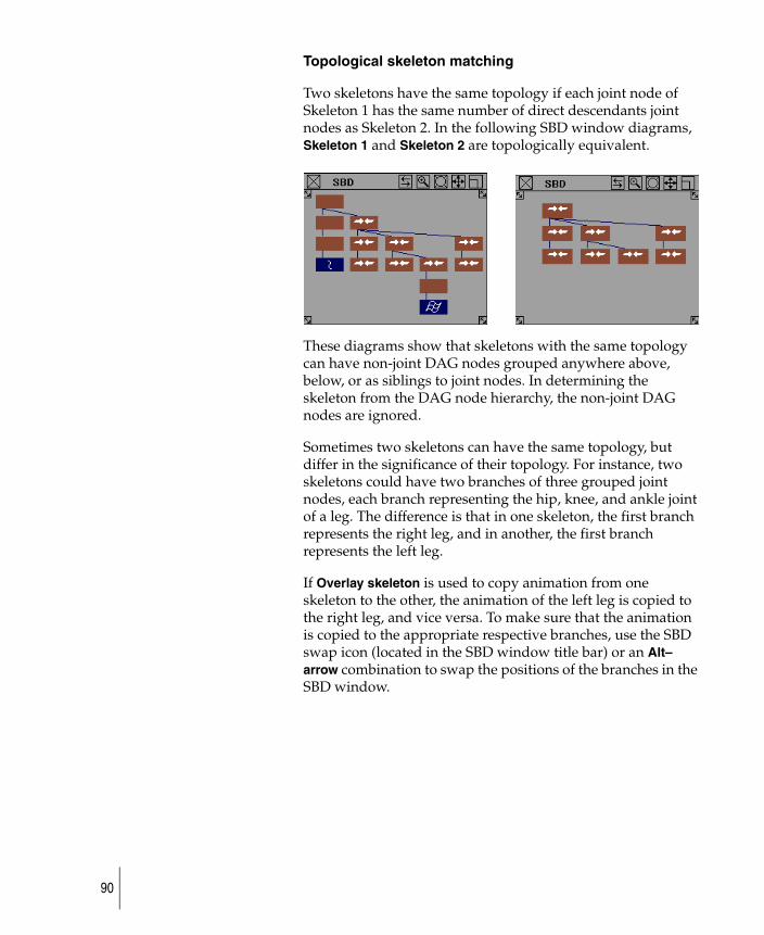
Topological skeleton matching
Two skeletons have the same topology if each joint node of Skeleton 1 has the same number of direct descendants joint nodes as Skeleton 2. In the following SBD window diagrams, Skeleton 1 and Skeleton 2 are topologically equivalent.
These diagrams show that skeletons with the same topology can have non-joint DAG nodes grouped anywhere above, below, or as siblings to joint nodes. In determining the skeleton from the DAG node hierarchy, the non-joint DAG nodes are ignored.
Sometimes two skeletons can have the same topology, but differ in the significance of their topology. For instance, two skeletons could have two branches of three grouped joint nodes, each branch representing the hip, knee, and ankle joint of a leg. The difference is that in one skeleton, the first branch represents the right leg, and in another, the first branch represents the left leg.
If Overlay skeleton is used to copy animation from one skeleton to the other, the animation of the left leg is copied to the right leg, and vice versa. To make sure that the animation is copied to the appropriate respective branches, use the SBD swap icon (located in the SBD window title bar) or an Alt–arrow combination to swap the positions of the branches in the SBD window.
90
Draw a skeleton
Use Animation > IK > New skeleton to create a skeleton that is defined by pivot points or joint positions.
● Refresh you memory with the definitions of Skeletons and Inverse kinematics terms before proceeding.
● Decide how complex your skeleton will be. If your intention is a simple animation.
● Choose the single-chain solver option. If you animation will involve rotations of joints in all directions use the multi-chain solver option.
To create joint nodes
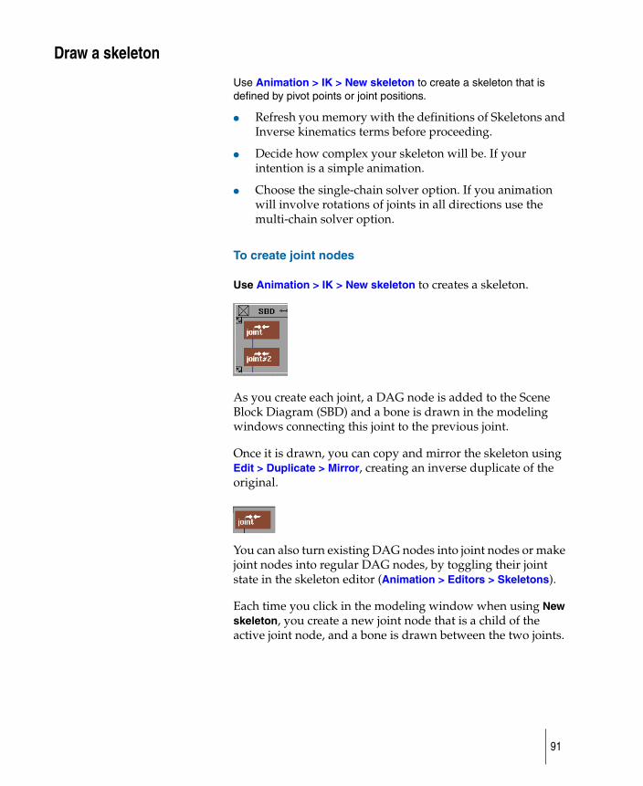
Use Animation > IK > New skeleton to creates a skeleton.
As you create each joint, a DAG node is added to the Scene Block Diagram (SBD) and a bone is drawn in the modeling windows connecting this joint to the previous joint.
Once it is drawn, you can copy and mirror the skeleton using Edit > Duplicate > Mirror, creating an inverse duplicate of the original.
You can also turn existing DAG nodes into joint nodes or make joint nodes into regular DAG nodes, by toggling their joint state in the skeleton editor (Animation > Editors > Skeletons).
Each time you click in the modeling window when using New skeleton, you create a new joint node that is a child of the active joint node, and a bone is drawn between the two joints.
91
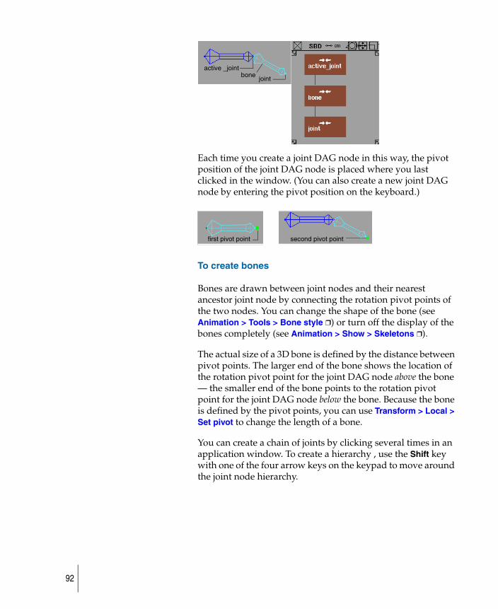
Each time you create a joint DAG node in this way, the pivot position of the joint DAG node is placed where you last clicked in the window. (You can also create a new joint DAG node by entering the pivot position on the keyboard.)
To create bones
Bones are drawn between joint nodes and their nearest ancestor joint node by connecting the rotation pivot points of the two nodes. You can change the shape of the bone (see Animation > Tools > Bone style ❒) or turn off the display of the bones completely (see Animation > Show > Skeletons ❒).
The actual size of a 3D bone is defined by the distance between pivot points. The larger end of the bone shows the location of the rotation pivot point for the joint DAG node above the bone — the smaller end of the bone points to the rotation pivot point for the joint DAG node below the bone. Because the bone is defined by the pivot points, you can use Transform > Local > Set pivot to change the length of a bone.
You can create a chain of joints by clicking several times in an application window. To create a hierarchy , use the Shift key with one of the four arrow keys on the keypad to move around the joint node hierarchy.
active _joint bone joint
first pivot point second pivot point
92
Display skeleton bones
How to display of skeleton bones and their associated constraints or IK handles in application windows on or off.
1 Create a skeleton using Animation > IK > New skeleton or the skeleton editor (Animation > Editors > Skeletons). The skeleton is displayed with bone-like geometry.
2 Choose Animation > Show > Skeletons to turn off the display of these bones. All the skeletons in all the windows are not displayed. To turn the display back on, select the function again.
93
Add IK handles to your skeleton
Use inverse kinematics IK handles to control the movement of different parts of your skeleton without disturbing the rest of the skeleton.
Animation > IK > Add IK handle ❑ is a continuous-action tool in which you add IK handles one at a time to a skeleton. To add single-chain handles, choose Single-chain in the option box for this tool. Then, select the root joint, and finally the end effector joint. The tool is still active after this operation, so you can continue to select other parts of the skeleton to put other IK handles on.
To add IK handles
1 Choose Animation > IK > Add IK handle ❑ or click its icon.
2 The system prompts:
Pick a joint as the root of a single-chain (multi-chain or spline) handle.
Pick a root joint to start the handle. (You can drag a pick box around a joint to select it.)
3 The system prompts:
Pick a descendant joint as the end-effector of the single chain (multi-chain or spline) handle.
Pick an end joint.
4 If you created a spline handle and you did not select Create Curve to create a new curve, the system prompts:
Pick a curve node as the target of the spline handle.
Pick the curve.
5 After you create a handle, the system prompts you to create another.
6 To view, change, or turn off the parameters of a handle, open the Information window and select the handle.
7 Limits and joint information about a handle can be edited in the Skeleton Editor. To see handle information, choose Handles from the List Type pop-up menu in the Skeleton Editor (Animation > Editors > Skeletons).
94
Limitations
● If you select Single-Chain solver or Spline-handle solver from the Add IK Handles Options box, the handle is not created if it will overlap any existing handle. However, it is acceptable for a Single-Chain handle to share its root/end-effector with a Multi-Chain handle end-effector/root.
● Joints can be the end-effector for a maximum of one handle. This restriction prevents handles from overlapping in the modeling windows, thereby allowing you to pick a particular handle. If you need two handles at the same point in the skeleton, you can add additional joints rooted at the same parent.
● Joints with handles are represented in the SBD window by a handle icon.
● A handle is always drawn from the joint it controls as the end-effector. If you transform the skeleton chain, the handle snaps to maintain its position at the joint.
● If a handle is animated, has an expression, or is constrained, then it will still be drawn at the end-effector joint, but its “goal” position for inverse kinematics purposes is the animated/expressioned/constrained position.
● Although handles are not displayed in the SBD window, you can still select them. Handle names appear in the Information Window, Action Window, or any other lister that displays names.
● Multi-chain or single-chain handles can be both position goals and orientation goals. A position goal handle puts the end-effector joint at the handle’s rotate pivot point position. An orientation goal handle orients the end-effector joint to match the orientation of the handle.
Tips for using the spline handles
You can control the spline handles in the Modeling window in several ways:
If you pick a root handle, either:
● Use Transform > Move and the left mouse button to move the chain along the curve.
95

● Choose Transform > Rotate and the left mouse button to roll the chain.
If you pick a master handle, use Transform > Rotate and the left mouse button to twist the chain.
To control the shape of the skeleton
You may want to use spline IK to control the shape of the skeleton, but not its position in space. This is useful if you want one curve to control the shape of a number of similar objects in different locations. To do this:
1 Constrain the root joint of the skeleton to the desired object.
2 Create a spline handle.
96
Creating a neutral pose for IK skeletons
Use Animation > IK > Set rest pose to define a neutral position.
The single-chain IK solver uses a rest pose from which all its unique solutions initiate. The rest pose is a set of values for each joint that provide an initial value for the IK solution.
Each skeleton joint “remembers” a rest value for its translation and rotation, X, Y, and Z values. The rest pose can be copied and mirrored onto a similar skeleton. For information on reverting to a rest pose, see Returning joints and IK skeletons to a rest pose (page 98).
To create a neutral pose for an IK skeleton
1 Create a skeleton using Animation > IK > New skeleton.
2 Position the skeleton as required, using Animation > Pick > Jointand the necessary Transform tools.
3 Choose Animation > IK > Set rest pose.
Alternatively, you can pick an IK handle to set a rest pose for all joints on the IK chain.
97
Returning joints and IK skeletons to a rest pose
Using Animation > IK > Assume rest pose to return a skeleton to its neutral position.
Each skeleton joint can assume a rest value for its translation, rotation, X, Y, and Z values. You can also return a joint or a regular node back to its neutral pose (that is, having its translation, rotation, X, Y, and Z values set to be zero).
The rest pose and neutral pose are the same by default. The rest pose can be changed by using Animation > IK > Set rest pose. For more information, see Creating a neutral pose for IK skeletons (page 97).
How to return a skeleton to a neutral or rest pose
1 Create a rest pose using Animation > IK > Set rest pose.
2 Reposition the skeleton as required using Animation > Pick > Joint and Transform tools.
3 Choose Animation > IK > Assume rest pose to return the skeleton to its rest pose.
You can also pick an IK handle for all joints on the IK chain to assume a rest pose.
98
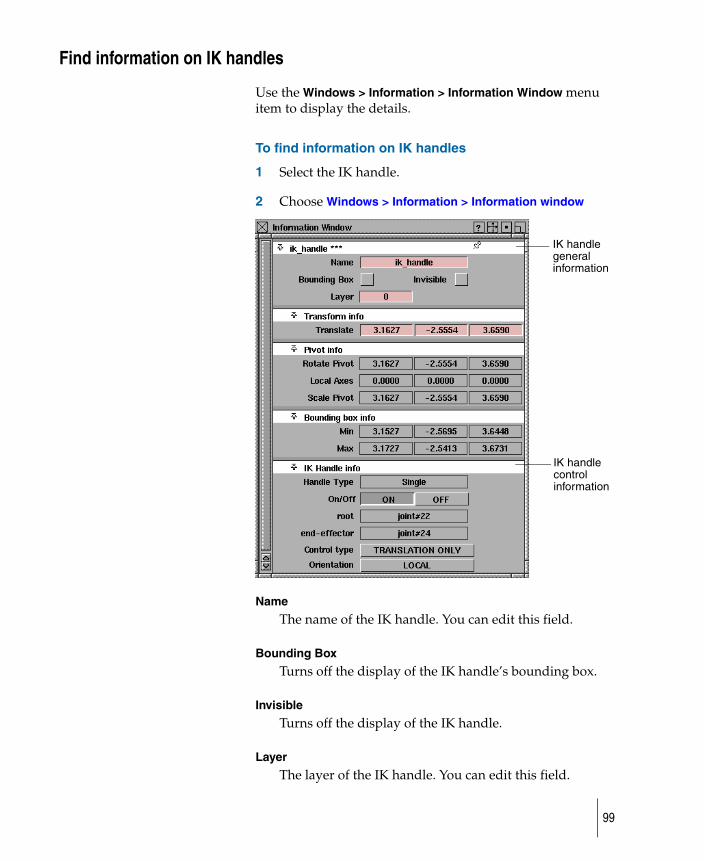
Find information on IK handles
Use the Windows > Information > Information Window menu item to display the details.
To find information on IK handles
1 Select the IK handle.
2 Choose Windows > Information > Information window
Name
The name of the IK handle. You can edit this field.
Bounding Box
Turns off the display of the IK handle’s bounding box.
Invisible
Turns off the display of the IK handle.
Layer
The layer of the IK handle. You can edit this field.
IK handle general information
IK handle control information
99
Translate
The handle’s translation coordinates. These are the only editable coordinates at this time because under Control type, TRANSLATION ONLY is chosen. The rotation and scale are not used to control the handle’s behavior.
Rotate Pivot
The handle’s rotation pivot coordinates.
Local Axes
The handle’s local axes coordinates.
Scale Pivot
The handle’s scaling pivot coordinates.
Bounding Box Min/Max
The limits placed on the handles’s bounding box, which is made up of the Limb axis and Plane indicator.
Handle Type
The type of the IK handle: single, multi, or spline.
On/Off
Click these buttons to turn the IK handle on or off. When the handle is turned off, it is still visible but has no effect on the IK chain. To hide it completely, click Invisible at the top of the IK handle section.
root
The top-most joint in the skeleton hierarchy affected by the IK handle.
end-effector
The bottom-most joint in the skeleton hierarchy affected by the IK handle.
On Off
100
Control type
A single-chain IK handle has three levels of control accessed from the Control type pop-up menu.
◆ TRANSLATION ONLY — this is the default control setting, suitable for most basic IK use. TRANSLATION ONLY means that you can only move or animate the IK handle’s translation channels.
◆ PLANE ROTATION — this setting gives you more in-depth control of the IK handle. It lets you rotate the skeleton plane, the plane in which the joints contained in the IK handle lie (if all the joints of the IK handle do not lie in one plane, a “best” fit plane is chosen). When you choose this option, you can rotate the IK handle using the value in the Plane rotate box, letting you re-orient the plane indicator, and subsequently the skeleton plane, to create more complex motion in the chain.
◆ You can also control the rotation of the plane axis by picking the IK handle and using the left mouse button with the Rotate tool (Transform > Rotate).
◆ PLANE/POLE ROTATION — this setting provides advanced, specialized control of the IK handle with a new set of options. In some cases, the combination of translation and plane rotation might cause the IK solution to flip uncontrollably. Set the two Pole rotate box values to alter the plane of the skeleton, while keeping the pole in the same orientation relative to the skeleton plane.
◆ Use the middle and right mouse buttons to rotate the IK solution’s Pole Axis and its projection.
101
The Pole order field is used to determine which two degrees of freedom are to be used to rotate the Pole Axis. In the earlier example illustrating plane rotation, the skeleton was drawn in the XY plane. Thus the Pole Axis is automatically positioned along the Z-axis (that is, perpendicular to the skeleton plane) when the IK handle is created, and the pole order is ZXY. This means that the Pole Axis is created parallel to the IK handle’s Z-axis (and thus given the blue Z-axis color), and its orientation is adjusted by applying a local X rotation, then a Y rotation, to the Pole Axis.
Orientation
The IK handle solution orients itself to a coordinate system to work. The coordinate system matches either the joint (LOCAL) or scene (WORLD) orientation.
When to use plane rotation settings for IK handles
If the IK chain never needs to change orientation from its rest position, the default Translation Only setting will be all you need to animate the skeleton. For example, if the legs of a simple biped character in a walk cycle are oriented in a constant direction (that is, the knees always point forward), the IK handles for the legs will only need translation.
102
However, if that same biped character needs to have a “bow-legged” or “knock-kneed” appearance or if the character is dancing, you might want to rotate the skeleton plane of both legs to achieve this effect. In this case, choose the Plane Rotation setting for those handles in the Information Window, and adjust the Plane Rotate fields accordingly.
Using the plane/pole rotation setting
You will need to adjust the rotation of the Pole Axis, through the “Plane/Pole Rotation” setting, only if the skeleton chain is to be animated through an extremely wide range of motion in the scene. Specifically, if the limb axis of the chain comes near the Pole Axis, an undesirable “flipping” of the chain may occur; generally, you will want to move/animate the Pole Axis so that the handle’s limb axis does not come too close to it during a given scene.
When you create a single-chain IK handle on a chain, a Pole Axis is created perpendicular to the skeleton plane in its rest position. As long as the chain is not contorted very far from this position, and the limb axis of the chain doesn’t approach the Pole Axis, this default position of the Pole Axis is suitable for animating the skeleton. Otherwise, adjusting or animating the Pole Axis may be necessary to avoid flipping in the chain.
Complex single-chain example
Below is an example of two torsos and how different types of arm movements are achieved through POLE/PLANE ROTATION.
In this example, the two torsos are identical and both have IK handles on the left arms. The default value for Plane rotate is 90 degrees. The default value for Pole rotate Y and Z is zero degrees. The left torso requires a drinking motion, while the right torso will perform a jumping motion.
103
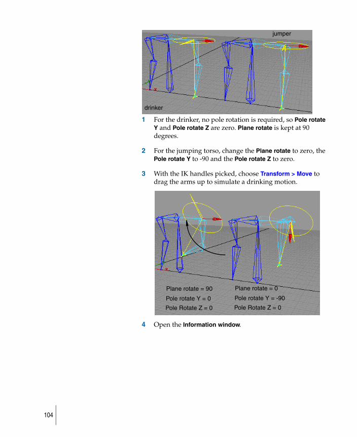
1 For the drinker, no pole rotation is required, so Pole rotate Y and Pole rotate Z are zero. Plane rotate is kept at 90 degrees.
2 For the jumping torso, change the Plane rotate to zero, the Pole rotate Y to -90 and the Pole rotate Z to zero.
3 With the IK handles picked, choose Transform > Move to drag the arms up to simulate a drinking motion.
4 Open the Information window.
drinker
jumper
Plane rotate = 90
Pole rotate Y = 0
Pole Rotate Z = 0
Plane rotate = 0
Pole rotate Y = -90
Pole Rotate Z = 0
104
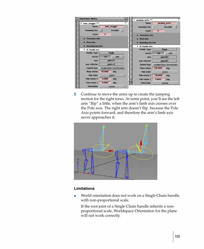
5 Continue to move the arms up to create the jumping motion for the right torso. At some point, you’ll see the left arm “flip” a little, when the arm’s limb axis crosses over the Pole axis. The right arm doesn’t flip because the Pole Axis points forward, and therefore the arm’s limb axis never approaches it.
Limitations
● World orientation does not work on a Single Chain handle with non-proportional scale.
If the root joint of a Single Chain handle inherits a non-proportional scale, Worldspace Orientation for the plane will not work correctly.
3
5
105
● If the joint angle animation output for Single Chain IK jumps from -180 or 180 degrees (or from 180 to -180 degrees) from one frame to the next, motion blur will not work properly.
Use the motion blur compensation option in Run IK. This will insert additional keyframes at the motion blur sample points near the jumps.
● Models with constraints or expression animation on joints with IK might play back with inconsistent motion.
106
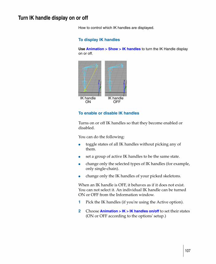
Turn IK handle display on or off
How to control which IK handles are displayed.
To display IK handles
Use Animation > Show > IK handles to turn the IK Handle display on or off.
To enable or disable IK handles
Turns on or off IK handles so that they become enabled or disabled.
You can do the following:
● toggle states of all IK handles without picking any of them.
● set a group of active IK handles to be the same state.
● change only the selected types of IK handles (for example, only single-chain).
● change only the IK handles of your picked skeletons.
When an IK handle is OFF, it behaves as if it does not exist. You can not select it. An individual IK handle can be turned ON or OFF from the Information window.
1 Pick the IK handles (if you're using the Active option).
2 Choose Animation > IK > IK handles on/off to set their states (ON or OFF according to the options' setup.)
IK handle IK handle ON OFF
107
Making a mirror copy
Edit > Duplicate > Mirror enables you to create a symmetrical copy of hierarchies according to an axis plane.
This works for skeletons as well as ordinary hierarchies and mirrors IK handles, constraints, rest poses, limits, animation, and selection handles.
With this function, you can do the following:
● Create real nodes for mirrored hierarchies, including the geometry.
(By contrast, Layers > Symmetry makes the symmetry by instances, so the geometry is not really duplicated.)
● Create a mirror copy starting from any level of a hierarchy, so that not only geometry, but also the complete hierarchy, animation controlling IK handles and constraints, and joint attributes are mirrored across the specified axis plane.
(By contrast, while Layers > Symmetry lets you use an arbitrary plane of symmetry, only the geometry is made symmetric-that is, only the leaf level is affected.
To make the best use of Mirror, create your character at the origin and then transform the character (and do any cluster attachment) only after mirroring is complete.
Select Edit > Duplicate > Mirror to open the Mirror Options box. From there, you can select two types of mirroring and three mirroring planes.
Mirror Type: Duplicate
Lets you pick a branch as the source branch. The tool duplicates the branch and mirrors its nodes on the new branch.
1 Choose Edit > Duplicate > Mirror.
2 Pick a branch of a hierarchy.
108
A new branch is created as the sibling of the picked one. The new branch is mirrored across the plane defined in the option box (Mirror Across settings). All IK handles, constraints, animations, and skeletons on the branch are also duplicated and mirrored.
You can also pick the branch and then select the Mirror item.
Mirror Type: Reshape
Lets you pick an existing branch as the destination (rather than have the tool create it). Geometries are not mirrored for this option.
1 Choose Edit > Duplicate > Mirror.
2 Pick the branch that you want to reshape.
3 Pick another branch that you want to be the source of the mirror.
The first branch is reshaped as a mirror of the second branch. All IK handles, constraints, animations, and skeletons on the first branch are replaced by new objects copied and mirrored according to the second branch.
Mirror Across
Mirror provides three mirroring planes under world space. This option specifies the plane to use for later mirror operations.
1 Choose Edit > Duplicate > Mirror to open the Mirror Options box.
2 Choose the plane to use: XY, YZ or XZ.
109
Run IK to render your animation
Animation > IK > Run IK creates an animation using multi-chain IK handles attached to a skeleton so that the animation may be rendered.
1 Create a skeleton using Animation > IK > New skeleton.
2 Choose Animation > IK > Add IK handle to attach IK handles to various joints of the skeleton.
3 Animate the IK handles using any of the StudioTools animation tools.
4 Set up your skeleton to be in the configuration that you want it to be in for the first frame of animation.
5 Pick the root of the skeleton and choose Animation > IK > Run IK.
You can view the skeleton animation through all the frames of the constraint animation. At the end of this operation, the skeleton is animated using its IK handles.
110

Work with IK chain solversHow three types of IK chain solves are used to set up character motion: Single chain solver, Multi-chain solver and the Spline-chain solver.
111

Use the single-chain solver
Use the single-chain IK solver to set up character motion very quickly and adjust the motion in a highly visual way.
The single-chain IK solver option can be set within the Animation > IK > Add IK handle options window.
Unique / no Run IK
With the single-chain solver, the solution is unique, which means that the behavior of the skeleton is the same whether the animation is played forward or backward, whether a constraint/handle is moved away and back, and so on. Therefore, you can interactively move and play back your skeleton motion, and render, without needing to use Run IK.
With the multi-chain IK solver, skeletons have non-unique behavior; that is, the motion of joints can change unpredictably, depending on whether you play back the animation, do a viewframe, move a constraint, or undo a transformation. The solution to this problem is to do a separate, non-interactive operation to “bake” the skeleton motion using the Run IK tool. (To render a Multi-Chain Solution, you must use Run IK before writing out the SDL file.)
Non-overlapping handles
With the single-chain solver, you can put only one handle on each part of a skeleton. For example, you can have one handle for each arm (shoulder to wrist), one handle on each finger (first knuckle to fingertip), etc. This is very different from the multi-chain IK, in which handles can share joints, and generally overlap considerably.
112
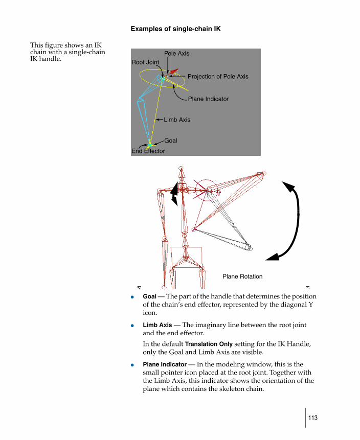
Examples of single-chain IK
This figure shows an IK chain with a single-chain IK handle.
● Goal — The part of the handle that determines the position of the chain’s end effector, represented by the diagonal Y icon.
● Limb Axis — The imaginary line between the root joint and the end effector.
In the default Translation Only setting for the IK Handle, only the Goal and Limb Axis are visible.
● Plane Indicator — In the modeling window, this is the small pointer icon placed at the root joint. Together with the Limb Axis, this indicator shows the orientation of the plane which contains the skeleton chain.
Pole Axis
Plane Indicator
Limb Axis
Root Joint
Goal
Projection of Pole Axis
End Effector
Plane Rotation
113
Using the rotation of the IK handle, you can rotate this plane, together with the chain, around the Limb Axis. See the diagram above.
The Plane Indicator is visible only with the Plane Rotation or Plane/Pole Rotation settings for the IK Handle.
● Pole Axis — With the single-chain IK, there is a Pole Axis, which the chain depends on for its orientation. If you move the handle so that the Limb Axis crosses this Pole Axis, the chain will “flip” by 180 degrees. As a result, it is sometimes useful to adjust the Pole’s orientation so the Limb Axis does not cross the Pole Axis for a given shot using the chain.
The Pole Axis is shown in the modeling window by a line segment with an “up” arrow at its tip. A projection of this Pole Axis is shown as a dashed line segment drawn to the Plane Indicator’s rotation disc.
The Pole Axis is visible only with the advanced-level “Plane/Pole Rotation” setting for the IK Handle.
114
Create a simple spine chain
Bone chains are not limited to living creatures. A desk lamp is a simple bone chain. Using a chain of bones, you can easily create a lamp by clicking and forming sections from the base of the lamp to the shade.
Click here first
Second click
Third clickFourth click
Fifth click
Sixth click
115
Create a human-like character
How to draw human skeleton forms.
To draw the right leg
1 Choose Animation > IK > New skeleton.
2 Click to define the position of the pelvis, the right hip, the right knee, the right ankle, and finally the right toe.
If you keep clicking now, you’ll keep adding joints to the end of the right toe.
To draw the left leg
To make the left leg, you want the next joint DAG node you create to be a child of the pelvis node.
3 Use the Shift-Up arrow combination to move up the hierarchy until the pelvis is active. You can do this in either the SBD or modeling window.
You can also create the left leg by using Edit > Duplicate > Mirror.
4 Click to define the position of the left hip, knee, ankle, and toe as you did with the right leg.
2nd click(hip)
3rd click(knee)
(toe)5th click
4th click(ankle)
Click here first to define the start point
116
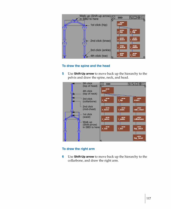
To draw the spine and the head
5 Use Shift-Up arrow to move back up the hierarchy to the pelvis and draw the spine, neck, and head.
To draw the right arm
6 Use Shift-Up arrow to move back up the hierarchy to the collarbone, and draw the right arm.
Walk up (Shift-up arrow)
1st click (hip)
2nd click (knee)
3rd click (ankle)
4th click (toe)
in SBD to here
5th click (top of head)
4th click(top of neck)
3rd click(collarbone)
2nd click(mid-chest)
1st click(waist)
Walk up(Shift-arrow)in SBD to here
117
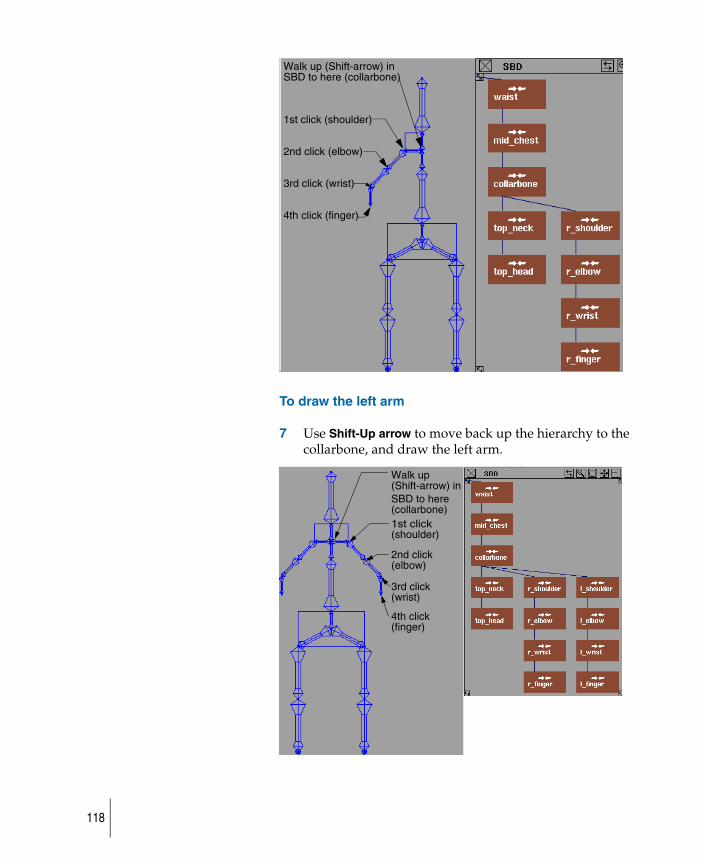
To draw the left arm
7 Use Shift-Up arrow to move back up the hierarchy to the collarbone, and draw the left arm.
Walk up (Shift-arrow) in SBD to here (collarbone)
1st click (shoulder)
2nd click (elbow)
3rd click (wrist)
4th click (finger)
Walk up
SBD to here
3rd click
2nd click
1st click
4th click
(Shift-arrow) in
(collarbone)
(finger)
(wrist)
(elbow)
(shoulder)
118
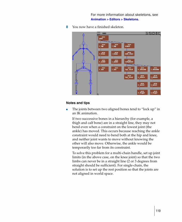
For more information about skeletons, see Animation > Editors > Skeletons.
8 You now have a finished skeleton.
Notes and tips
● The joints between two aligned bones tend to “lock up” in an IK animation.
If two successive bones in a hierarchy (for example, a thigh and calf bone) are in a straight line, they may not bend even when a constraint on the lowest joint (the ankle) has moved. This occurs because reaching the ankle constraint would need to bend both at the hip and knee, and neither joint wants to move without knowing the other will also move. Otherwise, the ankle would be temporarily too far from its constraint.
To solve this problem for a multi-chain handle, set up joint limits (in the above case, on the knee joint) so that the two limbs can never be in a straight line (2 or 3 degrees from straight should be sufficient). For single-chain, the solution is to set up the rest position so that the joints are not aligned in world space.
119
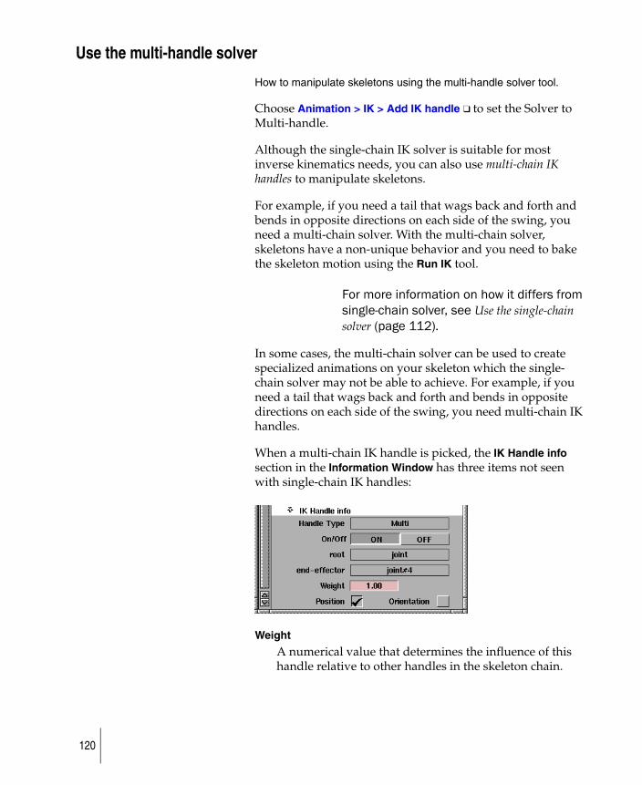
Use the multi-handle solver
How to manipulate skeletons using the multi-handle solver tool.
Choose Animation > IK > Add IK handle ❑ to set the Solver to Multi-handle.
Although the single-chain IK solver is suitable for most inverse kinematics needs, you can also use multi-chain IK handles to manipulate skeletons.
For example, if you need a tail that wags back and forth and bends in opposite directions on each side of the swing, you need a multi-chain solver. With the multi-chain solver, skeletons have a non-unique behavior and you need to bake the skeleton motion using the Run IK tool.
For more information on how it differs from single-chain solver, see Use the single-chain solver (page 112).
In some cases, the multi-chain solver can be used to create specialized animations on your skeleton which the single-chain solver may not be able to achieve. For example, if you need a tail that wags back and forth and bends in opposite directions on each side of the swing, you need multi-chain IK handles.
When a multi-chain IK handle is picked, the IK Handle info section in the Information Window has three items not seen with single-chain IK handles:
Weight
A numerical value that determines the influence of this handle relative to other handles in the skeleton chain.
120
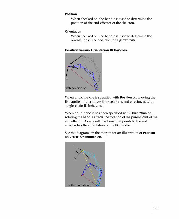
Position
When checked on, the handle is used to determine the position of the end-effector of the skeleton.
Orientation
When checked on, the handle is used to determine the orientation of the end-effector’s parent joint.
Position versus Orientation IK handles
When an IK handle is specified with Position on, moving the IK handle in turn moves the skeleton’s end effector, as with single-chain IK behavior.
When an IK handle has been specified with Orientation on, rotating the handle affects the rotation of the parent joint of the end effector. As a result, the bone that points to the end effector has the orientation of the IK handle.
See the diagrams in the margin for an illustration of Position on versus Orientation on.
Y
X
with position on
X Y
with orientation on
121

If both Position and Orientation are specified for a multi-chain IK handle, their behaviors are combined. The end effector moves with the IK handle, and the bone pointing to the end-effector is rotated to match the handle’s orientation.
Finding information on the IK handles
For more detailed information on IK handles refer to the section Create a simple spine chain (page 115).
122
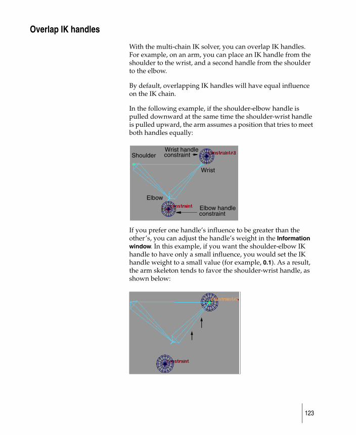
Overlap IK handles
With the multi-chain IK solver, you can overlap IK handles. For example, on an arm, you can place an IK handle from the shoulder to the wrist, and a second handle from the shoulder to the elbow.
By default, overlapping IK handles will have equal influence on the IK chain.
In the following example, if the shoulder-elbow handle is pulled downward at the same time the shoulder-wrist handle is pulled upward, the arm assumes a position that tries to meet both handles equally:
If you prefer one handle’s influence to be greater than the other’s, you can adjust the handle’s weight in the Information window. In this example, if you want the shoulder-elbow IK handle to have only a small influence, you would set the IK handle weight to a small value (for example, 0.1). As a result, the arm skeleton tends to favor the shoulder-wrist handle, as shown below:
Shoulder
Elbow
Wrist
Wrist handle constraint
Elbow handleconstraint
123
Set the IK handle rotation behavior
How to ’bake’ the IK handles.
When you use the multi-chain solver, you need to do an extra operation to ‘bake’ the IK handle behavior onto the rotations of the skeleton joints (use Animation > IK > Run IK). This operation creates keyframe animation directly on the skeleton joints so that the scene can be rendered or the skeleton’s animation can be further refined by editing the keyframes on the joints.
RunIK is optional with single-chain skeletons, but is required when using multi-chain IK handles.
124
Use the spline-handle solver
How to control the pieces of the skeleton chain.
You can use the spline handle to control a piece of skeleton chain. Using the spline handle, the skeleton chain matches a target spline curve. The spline handle makes tail, neck, or snake animation easier. There are four primary purposes of the spline solver:
● You can match the skeleton chain to the curve. Whenever you change the curve, the skeleton chain will follow the change and continue to match the curve. This allows you to animate the curve or animate the handle and correspondingly animate the skeleton chain.
● You can position the skeleton chain along the curve.
● You can roll the skeleton chain.
● You can twist the skeleton chain.
125

Bake animation and use Motion Blur compensation
How to apply motion blur to your animation.
There are times when you will want to generate animation curves in place of constraint or expression animation. The Bake plug-in provides the equivalent of Run IK for these cases. Bake creates animation curves for them with keyframes at regularly specified intervals that can be seen and edited by hand.
You can have all the constraints deleted after you’ve baked your animation by choosing the Delete Constraints option on the Bake options window.
If you are going to render an animation with Motion Blur (see Render > Globals for details), you may want to use Motion Blur compensation. The renderer evaluates the animation at a motion blur sample point, interpolating between these values.
The compensation only applies to animations translated from single-chain or spline IK handles.
Constraint animation is limited to a -180/+180 degree range. If the constraint jumps from -180 to +180, the object doesn’t actually move. But, the motion blur sampling reads a value between those degree ranges, and the object appears to flip, even though it shouldn’t. With the Motion Blur compensation, extra keyframes are created at the motion blur sample times wherever a flipping problem is detected.
126
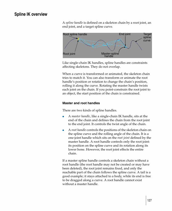
Spline IK overview
A spline handle is defined on a skeleton chain by a root joint, an end joint, and a target spline curve.
Like single-chain IK handles, spline handles are constraints affecting skeletons. They do not overlap.
When a curve is transformed or animated, the skeleton chain tries to match it. You can also transform or animate the root handle’s position or rotation to change the chain’s position, rolling it along the curve. Rotating the master handle twists each joint on the chain. If you point-constrain the root joint to an object, the start position of the chain is constrained.
Master and root handles
There are two kinds of spline handles.
● A master handle, like a single-chain IK handle, sits at the end of the chain and defines the chain from the root joint to the end joint. It controls the twist angle of the chain.
● A root handle controls the positions of the skeleton chain on the spline curve and the rolling angle of the chain. It is a one-joint handle which sits on the root joint defined by the master handle. A root handle controls only the root joint: its position on the spline curve and its rotation along its lower bone. However, the root joint effects the entire chain.
If a master spline handle controls a skeleton chain without a root handle (the root handle may not be created or may have been deleted), the root joint remains fixed, and only the reachable part of the chain follows the spline curve. A tail is a good example; it stays attached to a body, while its end is free to be dragged along a curve. A root handle cannot exist without a master handle.
Root spline handle
Root joint
End joint
handleMaster-spline
Targetsplinecurve
127
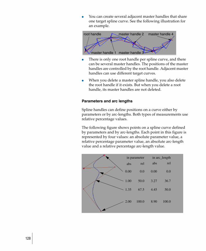
● You can create several adjacent master handles that share one target spline curve. See the following illustration for an example.
● There is only one root handle per spline curve, and there can be several master handles. The positions of the master handles are controlled by the root handle. Adjacent master handles can use different target curves.
● When you delete a master spline handle, you also delete the root handle if it exists. But when you delete a root handle, its master handles are not deleted.
Parameters and arc lengths
Spline handles can define positions on a curve either by parameters or by arc-lengths. Both types of measurements use relative percentage values.
The following figure shows points on a spline curve defined by parameters and by arc-lengths. Each point in this figure is represented by four values: an absolute parameter value, a relative percentage parameter value, an absolute arc-length value and a relative percentage arc-length value.
root handle
master handle 1
master handle 2
master handle 3
master handle 4
in parameter in arc_length
0.00.00 0.00 0.0
1.00 50.0 3.27 36.7
1.35 67.5 4.45 50.0
2.00 100.0 8.90 100.0
abs rel abs rel
128
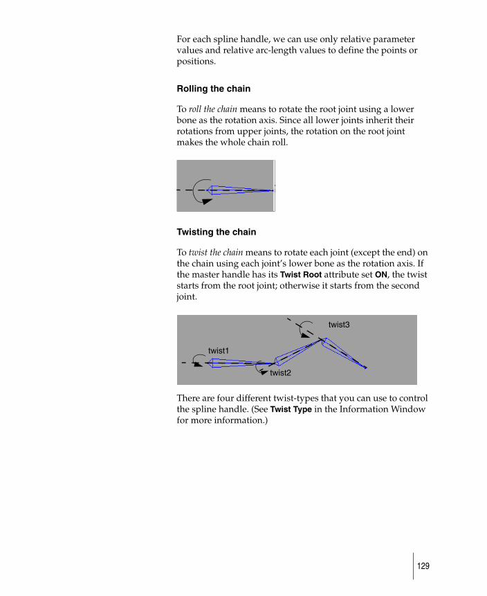
For each spline handle, we can use only relative parameter values and relative arc-length values to define the points or positions.
Rolling the chain
To roll the chain means to rotate the root joint using a lower bone as the rotation axis. Since all lower joints inherit their rotations from upper joints, the rotation on the root joint makes the whole chain roll.
Twisting the chain
To twist the chain means to rotate each joint (except the end) on the chain using each joint’s lower bone as the rotation axis. If the master handle has its Twist Root attribute set ON, the twist starts from the root joint; otherwise it starts from the second joint.
There are four different twist-types that you can use to control the spline handle. (See Twist Type in the Information Window for more information.)
twist1
twist2
twist3
129
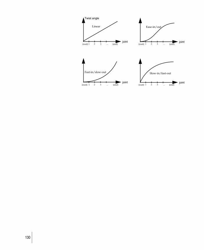
joint
Twist angle
1 2 3 ...joint
1 2 3 ...
joint2 3 ...
joint1 2 3 ...
Linear Ease-in/out
Slow-in/fast-outFast-in/slow-out
(root) (end) (root)
(root) (root) (end) (end)
(end)
1
130
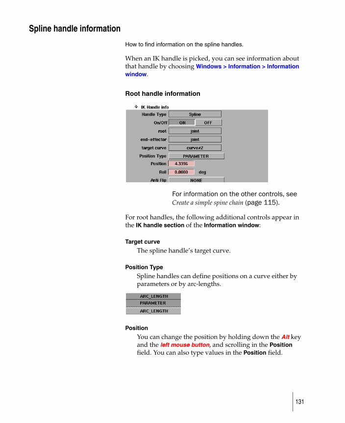
Spline handle information
How to find information on the spline handles.
When an IK handle is picked, you can see information about that handle by choosing Windows > Information > Information window.
Root handle information
For information on the other controls, see Create a simple spine chain (page 115).
For root handles, the following additional controls appear in the IK handle section of the Information window:
Target curve
The spline handle’s target curve.
Position Type
Spline handles can define positions on a curve either by parameters or by arc-lengths.
Position
You can change the position by holding down the Alt key and the left mouse button, and scrolling in the Position field. You can also type values in the Position field.
131
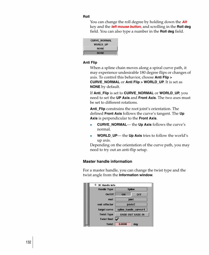
Roll
You can change the roll degree by holding down the Alt key and the left mouse button, and scrolling in the Roll deg field. You can also type a number in the Roll deg field.
Anti Flip
When a spline chain moves along a spiral curve path, it may experience undesirable 180 degree flips or changes of axis. To control this behavior, choose Anti Flip > CURVE_NORMAL or Anti Flip > WORLD_UP. It is set as NONE by default.
If Anti_Flip is set to CURVE_NORMAL or WORLD_UP, you need to set the UP Axis and Front Axis. The two axes must be set to different rotations.
Anti_Flip constrains the root joint’s orientation. The defined Front Axis follows the curve’s tangent. The Up Axis is perpendicular to the Front Axis.
◆ CURVE_NORMAL— the Up Axis follows the curve’s normal.
◆ WORLD_UP— the Up Axis tries to follow the world’s up axis.
Depending on the orientation of the curve path, you may need to try out an anti-flip setup.
Master handle information
For a master handle, you can change the twist type and the twist angle from the Information window.
132
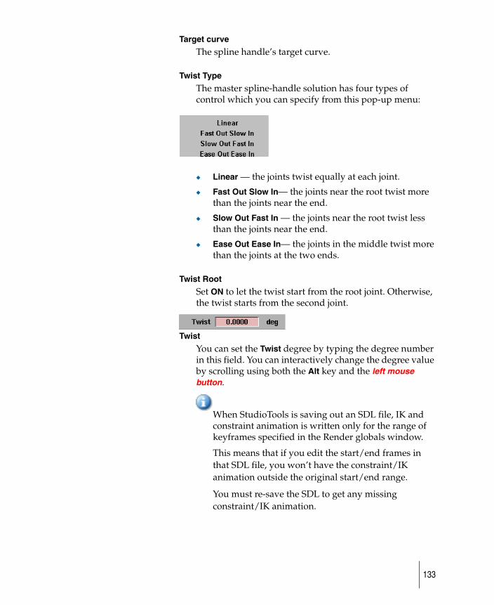
Target curve
The spline handle’s target curve.
Twist Type
The master spline-handle solution has four types of control which you can specify from this pop-up menu:
◆ Linear — the joints twist equally at each joint.
◆ Fast Out Slow In— the joints near the root twist more than the joints near the end.
◆ Slow Out Fast In — the joints near the root twist less than the joints near the end.
◆ Ease Out Ease In— the joints in the middle twist more than the joints at the two ends.
Twist Root
Set ON to let the twist start from the root joint. Otherwise, the twist starts from the second joint.
Twist
You can set the Twist degree by typing the degree number in this field. You can interactively change the degree value by scrolling using both the Alt key and the left mouse button.
When StudioTools is saving out an SDL file, IK and constraint animation is written only for the range of keyframes specified in the Render globals window.
This means that if you edit the start/end frames in that SDL file, you won’t have the constraint/IK animation outside the original start/end range.
You must re-save the SDL to get any missing constraint/IK animation.
133

Work with constraintsCreate any combination and number of point and orientation constraints on an object.
134
Create a constraint on an object
How to apply a restriction to a DAG node.
The term constraint describes a generalized restriction that can apply to any DAG node. A point constraint modifies the translations of an object to match the position of the object it is constrained to. Orientation and aim constraints modify the rotations of the constrained object so that its local axes match those of the constraint object (orientation), or the selected aim axis points at the constraint object (aim).
Create constraint translates or rotates the object that is being constrained to the position and orientation of the constraint. You can create any combination and number of point and orientation constraints on an object. You can also copy and mirror existing constraints onto a skeleton.
Create a constraint
1 Choose an object using Pick > Object, or pick an object DAG node in the SBD window.
2 Choose Animation > Tools > Create constraint from the menu bar.
Depending on the Constraint Type you have set in the Create Constraint Options window. You are prompted to pick either a joint or a node.
For example, the system prompts:Pick a joint or node to constrain.
3 Pick an object in the modeling or SBD window. You will see a selection handle or a jack (or both) appear next to the object, allowing you to use the new constraint.
You can later change the values of a constraint (but not its type or target) in the Constraint Information section of the Information window (choose Windows > Information > Information window).
Hints and Tips
In general it is not useful to apply a constraint directly to a skeleton joint. For example, if a point constraint is applied to a
135
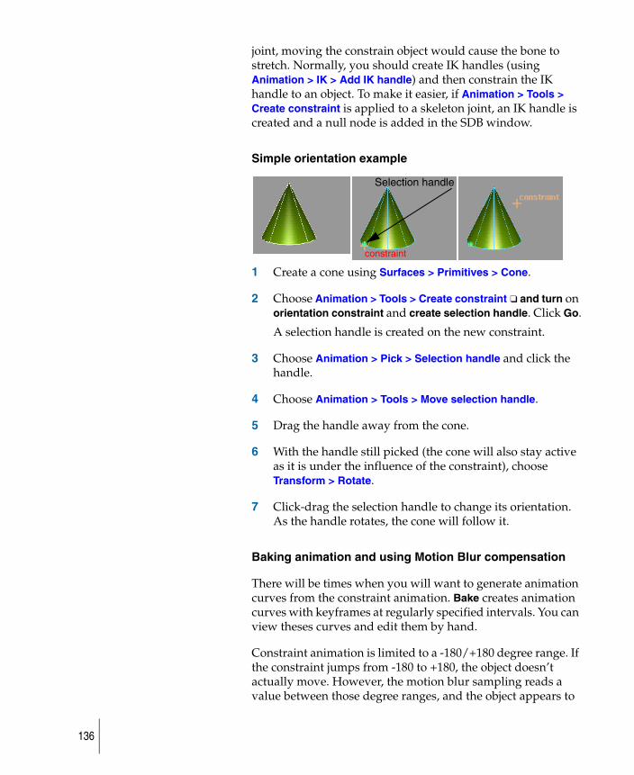
joint, moving the constrain object would cause the bone to stretch. Normally, you should create IK handles (using Animation > IK > Add IK handle) and then constrain the IK handle to an object. To make it easier, if Animation > Tools > Create constraint is applied to a skeleton joint, an IK handle is created and a null node is added in the SDB window.
Simple orientation example
1 Create a cone using Surfaces > Primitives > Cone.
2 Choose Animation > Tools > Create constraint ❑ and turn on orientation constraint and create selection handle. Click Go.
A selection handle is created on the new constraint.
3 Choose Animation > Pick > Selection handle and click the handle.
4 Choose Animation > Tools > Move selection handle.
5 Drag the handle away from the cone.
6 With the handle still picked (the cone will also stay active as it is under the influence of the constraint), choose Transform > Rotate.
7 Click-drag the selection handle to change its orientation. As the handle rotates, the cone will follow it.
Baking animation and using Motion Blur compensation
There will be times when you will want to generate animation curves from the constraint animation. Bake creates animation curves with keyframes at regularly specified intervals. You can view theses curves and edit them by hand.
Constraint animation is limited to a -180/+180 degree range. If the constraint jumps from -180 to +180, the object doesn’t actually move. However, the motion blur sampling reads a value between those degree ranges, and the object appears to
Selection handle
constraint
136
flip. With Bake, extra keyframes are created with the Motion Blur compensation at the motion blur sample times, wherever this flipping problem is detected. The sample points are at the frame, plus/minus the following value:
(RenderByFrame * ShutterAngle) / 720
Notes and tips
● When StudioTools is saving out an SDL file, IK and constraint animation is written only for the range of keyframes specified in the Render Globals window.
This means that if you edit the start/end frames in that SDL file, you won’t have the constraint/IK animation outside the original start/end range.
You must re-save the SDL to get any missing constraint/IK animation.
● The effects of invisible constraints are inconsistent. A constraint to an invisible object is not evaluated during playback, but is enforced during transformation of the constrained object.
Use Animation > Edit > Constraints on/off to enable/disable constraint updates instead of visibility.
137
Constrain one object to another object
Create UV point, orientation or aiming constraints on an object.
Constrain to creates constraints that translates or rotates the constrained objects to the position. You can create any combination and number of UV point, orientation, or aiming constraints on an object.
Constraining an object to another object
1 Select an object using Pick > Object, or pick an object DAG node in the SBD window.
2 Choose Animation > Tools > Constrain to.
The system prompts depend on the constraint type that you have set in the Constrain to Options window.
◆ If the Constraint Type is Point (the default), the system prompts:
Pick the DAG node whose rotate pivot will be a POINT constraint for the selected node.
◆ If the Constraint Type is Aim, the system prompts:Pick the DAG node which the node’s local x axis will AIM at.
◆ If the Constraint Type is Orientation, the system prompts:
Pick the DAG node whose local axis will be an ORIENTATION constraint for the selected node.
3 Pick an object in the modeling or SBD window that meets the criteria outlined in the prompt.
In the modeling view, a line may be shown to indicate the constraint. This line is only shown if the constraint is not met.
138
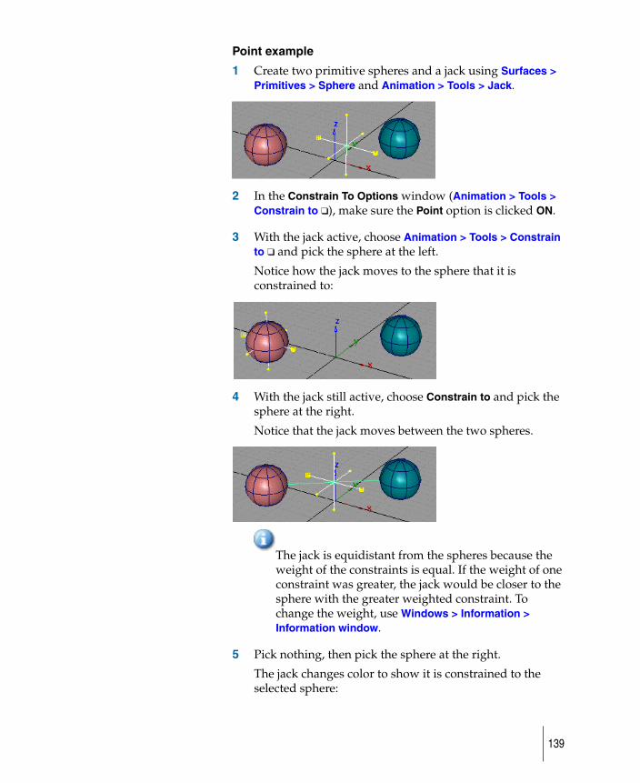
Point example
1 Create two primitive spheres and a jack using Surfaces > Primitives > Sphere and Animation > Tools > Jack.
2 In the Constrain To Options window (Animation > Tools > Constrain to ❑), make sure the Point option is clicked ON.
3 With the jack active, choose Animation > Tools > Constrain to ❑ and pick the sphere at the left.
Notice how the jack moves to the sphere that it is constrained to:
4 With the jack still active, choose Constrain to and pick the sphere at the right.
Notice that the jack moves between the two spheres.
The jack is equidistant from the spheres because the weight of the constraints is equal. If the weight of one constraint was greater, the jack would be closer to the sphere with the greater weighted constraint. To change the weight, use Windows > Information > Information window.
5 Pick nothing, then pick the sphere at the right.
The jack changes color to show it is constrained to the selected sphere:
139
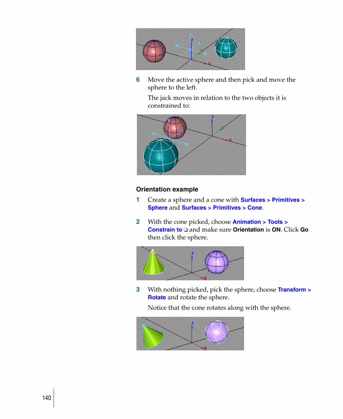
6 Move the active sphere and then pick and move the sphere to the left.
The jack moves in relation to the two objects it is constrained to:
Orientation example
1 Create a sphere and a cone with Surfaces > Primitives > Sphere and Surfaces > Primitives > Cone.
2 With the cone picked, choose Animation > Tools > Constrain to ❑ and make sure Orientation is ON. Click Go then click the sphere.
3 With nothing picked, pick the sphere, choose Transform > Rotate and rotate the sphere.
Notice that the cone rotates along with the sphere.
140
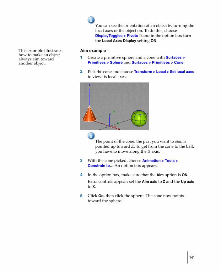
You can see the orientation of an object by turning the local axes of the object on. To do this, choose DisplayToggles > Pivots ❒ and in the option box turn the Local Axes Display setting ON.
This example illustrates how to make an object always aim toward another object.
Aim example
1 Create a primitive sphere and a cone with Surfaces > Primitives > Sphere and Surfaces > Primitives > Cone.
2 Pick the cone and choose Transform > Local > Set local axes to view its local axes.
The point of the cone, the part you want to aim, is pointed up toward Z. To get from the cone to the ball, you have to move along the X axis.
3 With the cone picked, choose Animation > Tools > Constrain to❑. An option box appears.
4 In the option box, make sure that the Aim option is ON.
Extra controls appear: set the Aim axis to Z and the Up axis to X.
5 Click Go, then click the sphere. The cone now points toward the sphere.
141
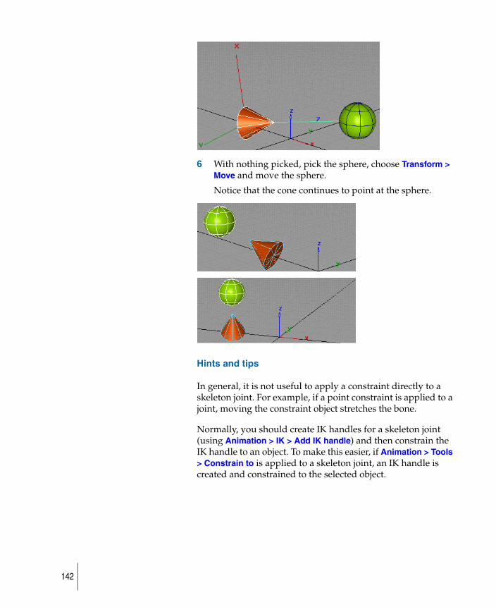
6 With nothing picked, pick the sphere, choose Transform > Move and move the sphere.
Notice that the cone continues to point at the sphere.
Hints and tips
In general, it is not useful to apply a constraint directly to a skeleton joint. For example, if a point constraint is applied to a joint, moving the constraint object stretches the bone.
Normally, you should create IK handles for a skeleton joint (using Animation > IK > Add IK handle) and then constrain the IK handle to an object. To make this easier, if Animation > Tools > Constrain to is applied to a skeleton joint, an IK handle is created and constrained to the selected object.
142

Edit UV constraints
How to pick and modify any UV constraint assigned to a constraint target object.
Edit UV constraints
1 Choose Animation > Tools > Edit uv constraint.
2 Pick the UV constraint target object or constrained object.
All of the UV constraints related to the picked object will be displayed as markers.
3 Pick a UV marker or Shift-select an object. The marker is picked when it turns red.
4 Click the UV marker and move it or enter the UV coordinates in the prompt line.
You can also edit a UV constraint from the Information window by opening the Constraint Info section.
UV constrainttarget object
UV marker
143
Turn constraints on or off
Use Animation > Edit > Constraints on/off to enable or disable constraints.
When a constraint is OFF, it behaves as if it does not exist.
This function makes it easier to turn on or turn off a group of constraints. For example, you can toggle states of all existing constraints without picking any of them; set constraints of a group of active objects to be the same state; make changes only on the selected types of constraints (say, only change point constraint); or make changes only to the constraints of your picked hierarchies. You can choose to use the constraints either on the constrained side, or the constraining side of the objects.
To turn constraints on or off
An individual constraint can be turned ON or OFF from the Information Window when the constrained object is picked.
1 If the Active option is on, pick the objects whose constraints you wish to affect.
2 Choose Animation > Edit > Constraints on/off to set their states (ON or OFF according to the options’ setup.)
144
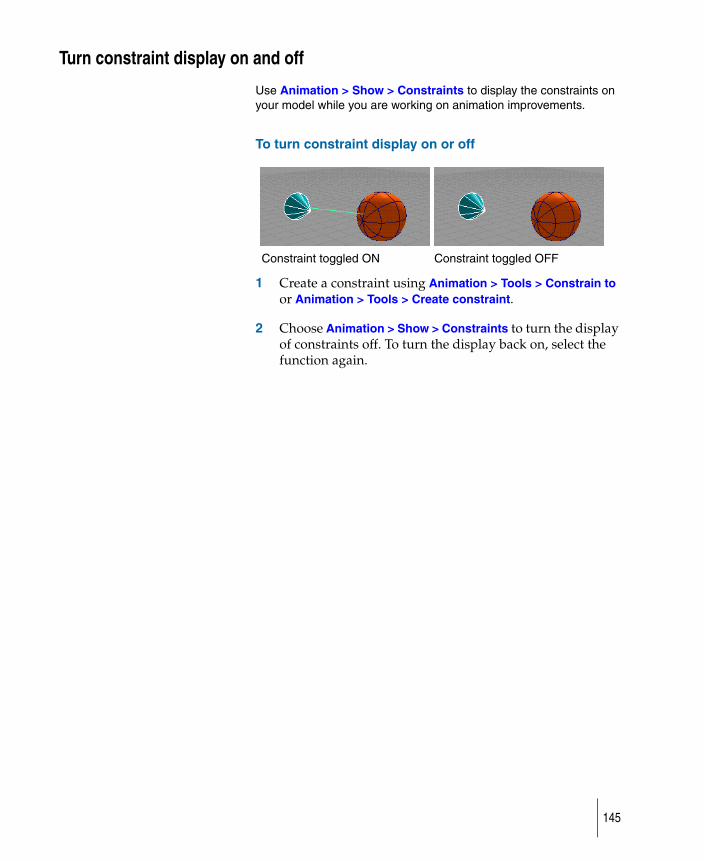
Turn constraint display on and off
Use Animation > Show > Constraints to display the constraints on your model while you are working on animation improvements.
To turn constraint display on or off
1 Create a constraint using Animation > Tools > Constrain to or Animation > Tools > Create constraint.
2 Choose Animation > Show > Constraints to turn the display of constraints off. To turn the display back on, select the function again.
Constraint toggled ON Constraint toggled OFF
145
Delete constraints
Use Delete > Animation > Delete constraints to remove constraints from your animation.
To delete constraints
1 Create a skeleton using Animation > IK > New skeleton, and add one or more constraints to the skeleton’s joint nodes using Animation > Tools > Create constraint.
2 Choose Delete > Animation > Delete constraints to delete the constraints on one of the joint nodes. A confirmation box appears, asking you if you want to delete constraints on selected DAG nodes.
3 Click YES or type the letter y to remove the constraints on the selected joint. No action is taken if you click NO or type the letter n.
146
Create animated deformed surfacesHow to deform surfaces in your animation.
147
Create clusters
How to transform and manipulate clusters as a single entity.
A cluster is an entity that logically groups an arbitrary list of CVs and DAG nodes so that they can be transformed and manipulated as a single entity. A cluster can be viewed as a type of object that has no geometry of its own, but refers to other geometry.
Creating a cluster
To create a cluster, pick all the objects and CVs that you want to put in the cluster and choose Animation > Create > Cluster. The CVs do not have to belong to the same piece of geometry. A cluster node is created with a DAG node above it. When this DAG node is transformed, each of the CVs in the cluster is transformed.
You can move the pivots of the cluster and then transform it using Transform > Rotate or Transform > Scale. The CVs of many objects can be transformed relative to a common pivot.
A cluster cannot contain elements that do not have CVs below them. For example, if a camera or light is picked when New cluster is invoked, the camera or light will not be included in the cluster. This is because the purpose of a cluster is to create deformations on object geometry, and cameras and lights contain no geometry.
Example
1 To create a cluster, first create two primitive spheres (Surfaces > Primitives > Sphere).
2 Pick the spheres using Pick > Object, or pick some of the CVs of each of the spheres.
3 Choose Animation > Create > Cluster.
148
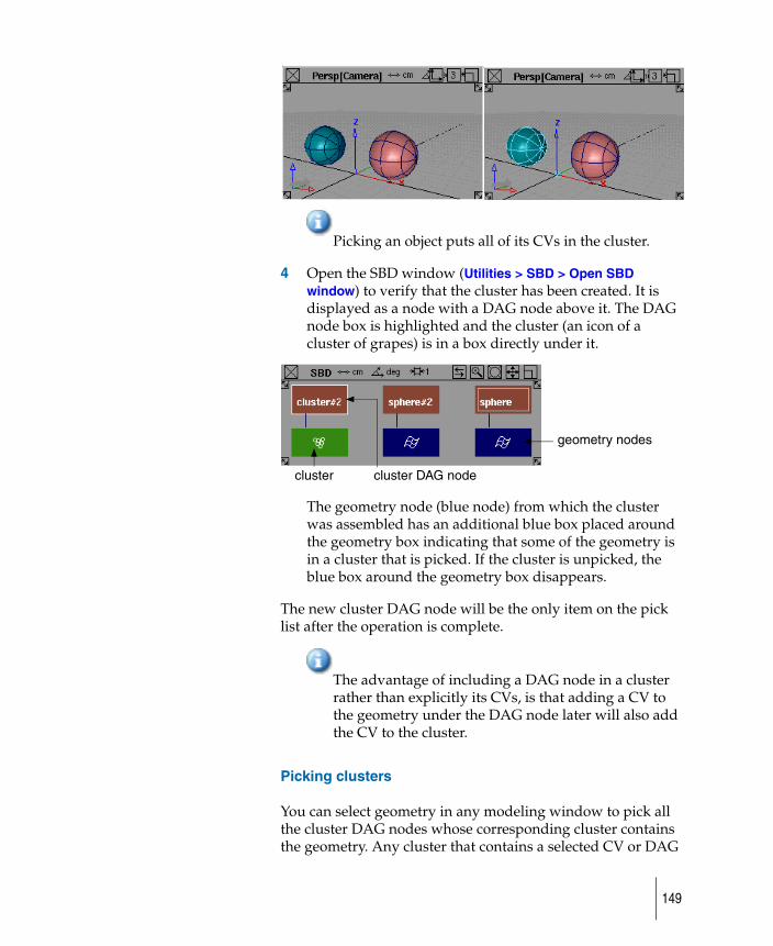
Picking an object puts all of its CVs in the cluster.
4 Open the SBD window (Utilities > SBD > Open SBD window) to verify that the cluster has been created. It is displayed as a node with a DAG node above it. The DAG node box is highlighted and the cluster (an icon of a cluster of grapes) is in a box directly under it.
The geometry node (blue node) from which the cluster was assembled has an additional blue box placed around the geometry box indicating that some of the geometry is in a cluster that is picked. If the cluster is unpicked, the blue box around the geometry box disappears.
The new cluster DAG node will be the only item on the pick list after the operation is complete.
The advantage of including a DAG node in a cluster rather than explicitly its CVs, is that adding a CV to the geometry under the DAG node later will also add the CV to the cluster.
Picking clusters
You can select geometry in any modeling window to pick all the cluster DAG nodes whose corresponding cluster contains the geometry. Any cluster that contains a selected CV or DAG
geometry nodes
cluster cluster DAG node
149
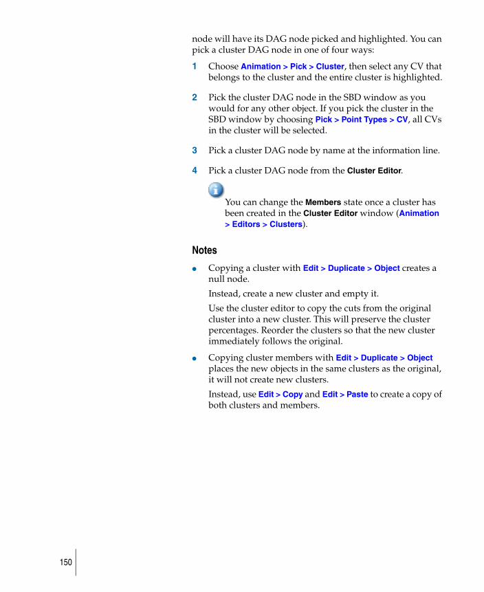
node will have its DAG node picked and highlighted. You can pick a cluster DAG node in one of four ways:
1 Choose Animation > Pick > Cluster, then select any CV that belongs to the cluster and the entire cluster is highlighted.
2 Pick the cluster DAG node in the SBD window as you would for any other object. If you pick the cluster in the SBD window by choosing Pick > Point Types > CV, all CVs in the cluster will be selected.
3 Pick a cluster DAG node by name at the information line.
4 Pick a cluster DAG node from the Cluster Editor.
You can change the Members state once a cluster has been created in the Cluster Editor window (Animation > Editors > Clusters).
Notes
● Copying a cluster with Edit > Duplicate > Object creates a null node.
Instead, create a new cluster and empty it.
Use the cluster editor to copy the cuts from the original cluster into a new cluster. This will preserve the cluster percentages. Reorder the clusters so that the new cluster immediately follows the original.
● Copying cluster members with Edit > Duplicate > Object places the new objects in the same clusters as the original, it will not create new clusters.
Instead, use Edit > Copy and Edit > Paste to create a copy of both clusters and members.
150
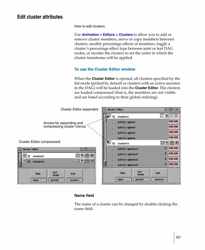
Edit cluster attributes
How to edit clusters.
Use Animation > Editors > Clusters to allow you to add or remove cluster members, move or copy members between clusters, modify percentage effects of members, toggle a cluster’s percentage effect type between joint or leaf DAG nodes, or reorder the clusters to set the order in which the cluster transforms will be applied.
To use the Cluster Editor window
When the Cluster Editor is opened, all clusters specified by the list mode (picked by default or clusters with an active ancestor in the DAG) will be loaded into the Cluster Editor. The clusters are loaded compressed (that is, the members are not visible and are listed according to their global ordering).
Name field
The name of a cluster can be changed by double-clicking the name field.
Cluster Editor compressed:
Cluster Editor expanded:
Arrows for expanding and compressing cluster menus
151

Cluster Editor buttons
The expand/compress cluster buttons let you expand a cluster to view each of its members, or to compress the cluster to show just the name of the cluster. When a cluster is expanded, members are displayed in the following order: first DAG nodes alphabetically by name, then surface CVs, curve CVs, and polyset vertices.
When a cluster is expanded to show its members, a member may be a DAG node. In this case, the DAG node has an expand member arrow to the left of its name. If this arrow is selected, the DAG node is expanded to show everything below it (for example, other grouped DAG nodes, or geometry CVs). If all the siblings of a cluster member are in the cluster (for example, all the CVs of an object are in the cluster), then the member has a compress arrow to the right of its name. If this arrow is selected, the parent DAG node replaces the member and its siblings in the cluster.
The percentage effect type buttons toggle the percentage effect type of the cluster. The joint percentage effect type tells the cluster to apply its percentage effects to the transformations in the first skeleton joint node that is above the cluster. Leaf node percentage effects tells the cluster to use the transformations in the DAG node directly above it.
The pick-in-modeler button updates the pick state in the modeler for the cluster and its members.
compress
expand
leaf node
joint
leaf node
locked
152
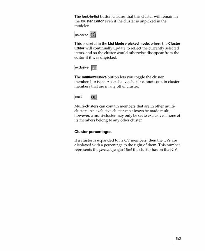
The lock-in-list button ensures that this cluster will remain in the Cluster Editor even if the cluster is unpicked in the modeler.
This is useful in the List Mode > picked mode, where the Cluster Editor will continually update to reflect the currently selected items, and so the cluster would otherwise disappear from the editor if it was unpicked.
The multi/exclusive button lets you toggle the cluster membership type. An exclusive cluster cannot contain cluster members that are in any other cluster.
Multi-clusters can contain members that are in other multi-clusters. An exclusive cluster can always be made multi; however, a multi-cluster may only be set to exclusive if none of its members belong to any other cluster.
Cluster percentages
If a cluster is expanded to its CV members, then the CVs are displayed with a percentage to the right of them. This number represents the percentage effect that the cluster has on that CV.
unlocked
exclusiveexclusive
multi
153
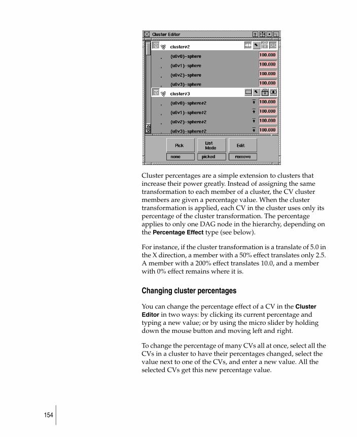
Cluster percentages are a simple extension to clusters that increase their power greatly. Instead of assigning the same transformation to each member of a cluster, the CV cluster members are given a percentage value. When the cluster transformation is applied, each CV in the cluster uses only its percentage of the cluster transformation. The percentage applies to only one DAG node in the hierarchy, depending on the Percentage Effect type (see below).
For instance, if the cluster transformation is a translate of 5.0 in the X direction, a member with a 50% effect translates only 2.5. A member with a 200% effect translates 10.0, and a member with 0% effect remains where it is.
Changing cluster percentages
You can change the percentage effect of a CV in the Cluster Editor in two ways: by clicking its current percentage and typing a new value; or by using the micro slider by holding down the mouse button and moving left and right.
To change the percentage of many CVs all at once, select all the CVs in a cluster to have their percentages changed, select the value next to one of the CVs, and enter a new value. All the selected CVs get this new percentage value.
154
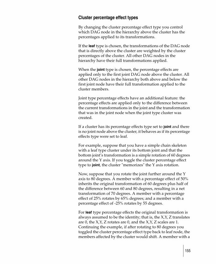
Cluster percentage effect types
By changing the cluster percentage effect type you control which DAG node in the hierarchy above the cluster has the percentages applied to its transformations.
If the leaf type is chosen, the transformations of the DAG node that is directly above the cluster are weighted by the cluster percentages of the cluster. All other DAG nodes in the hierarchy have their full transformations applied.
When the joint type is chosen, the percentage effects are applied only to the first joint DAG node above the cluster. All other DAG nodes in the hierarchy both above and below the first joint node have their full transformation applied to the cluster members.
Joint type percentage effects have an additional feature: the percentage effects are applied only to the difference between the current transformations in the joint and the transformation that was in the joint node when the joint type cluster was created.
If a cluster has its percentage effects type set to joint and there is no joint node above the cluster, it behaves as if its percentage effects type were set to leaf.
For example, suppose that you have a simple chain skeleton with a leaf type cluster under its bottom joint and that the bottom joint’s transformation is a simple rotation of 60 degrees around the Y axis. If you toggle the cluster percentage effect type to joint, the cluster "memorizes" the Y axis rotation.
Now, suppose that you rotate the joint further around the Y axis to 80 degrees. A member with a percentage effect of 50% inherits the original transformation of 60 degrees plus half of the difference between 60 and 80 degrees, resulting in a net transformation of 70 degrees. A member with a percentage effect of 25% rotates by 65% degrees; and a member with a percentage effect of -25% rotates by 55 degrees.
For leaf type percentage effects the original transformation is always assumed to be the identity; that is, the X,Y, Z translates are 0, the X,Y, Z rotates are 0, and the X,Y, Z scales are 1. Continuing the example, if after rotating to 80 degrees you toggled the cluster percentage effect type back to leaf node, the members affected by the cluster would shift. A member with a
155
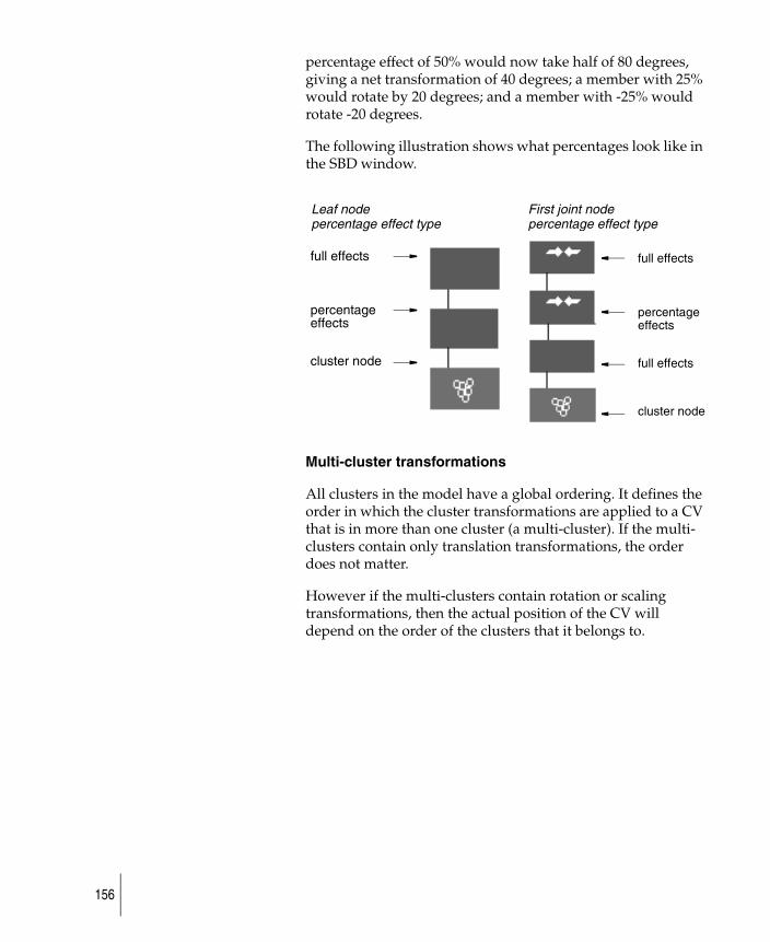
percentage effect of 50% would now take half of 80 degrees, giving a net transformation of 40 degrees; a member with 25% would rotate by 20 degrees; and a member with -25% would rotate -20 degrees.
The following illustration shows what percentages look like in the SBD window.
Multi-cluster transformations
All clusters in the model have a global ordering. It defines the order in which the cluster transformations are applied to a CV that is in more than one cluster (a multi-cluster). If the multi-clusters contain only translation transformations, the order does not matter.
However if the multi-clusters contain rotation or scaling transformations, then the actual position of the CV will depend on the order of the clusters that it belongs to.
Leaf nodepercentage effect type
First joint nodepercentage effect type
full effects
percentage
cluster node
full effects
percentage
full effects
cluster node
effects effects
156
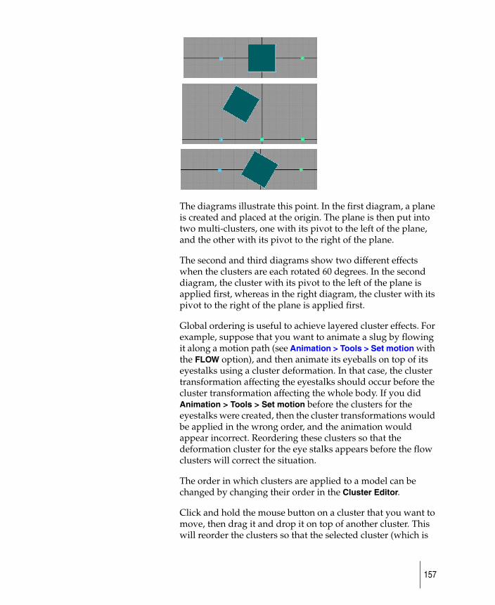
The diagrams illustrate this point. In the first diagram, a plane is created and placed at the origin. The plane is then put into two multi-clusters, one with its pivot to the left of the plane, and the other with its pivot to the right of the plane.
The second and third diagrams show two different effects when the clusters are each rotated 60 degrees. In the second diagram, the cluster with its pivot to the left of the plane is applied first, whereas in the right diagram, the cluster with its pivot to the right of the plane is applied first.
Global ordering is useful to achieve layered cluster effects. For example, suppose that you want to animate a slug by flowing it along a motion path (see Animation > Tools > Set motion with the FLOW option), and then animate its eyeballs on top of its eyestalks using a cluster deformation. In that case, the cluster transformation affecting the eyestalks should occur before the cluster transformation affecting the whole body. If you did Animation > Tools > Set motion before the clusters for the eyestalks were created, then the cluster transformations would be applied in the wrong order, and the animation would appear incorrect. Reordering these clusters so that the deformation cluster for the eye stalks appears before the flow clusters will correct the situation.
The order in which clusters are applied to a model can be changed by changing their order in the Cluster Editor.
Click and hold the mouse button on a cluster that you want to move, then drag it and drop it on top of another cluster. This will reorder the clusters so that the selected cluster (which is
157
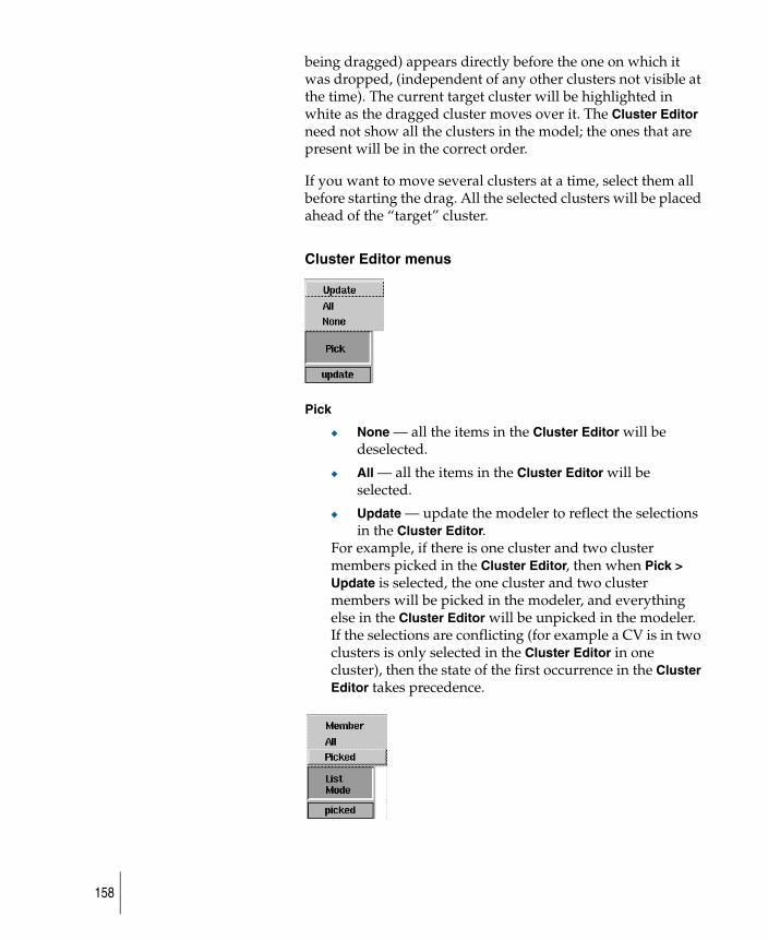
being dragged) appears directly before the one on which it was dropped, (independent of any other clusters not visible at the time). The current target cluster will be highlighted in white as the dragged cluster moves over it. The Cluster Editor need not show all the clusters in the model; the ones that are present will be in the correct order.
If you want to move several clusters at a time, select them all before starting the drag. All the selected clusters will be placed ahead of the “target” cluster.
Cluster Editor menus
Pick
◆ None — all the items in the Cluster Editor will be deselected.
◆ All — all the items in the Cluster Editor will be selected.
◆ Update — update the modeler to reflect the selections in the Cluster Editor.
For example, if there is one cluster and two cluster members picked in the Cluster Editor, then when Pick > Update is selected, the one cluster and two cluster members will be picked in the modeler, and everything else in the Cluster Editor will be unpicked in the modeler. If the selections are conflicting (for example a CV is in two clusters is only selected in the Cluster Editor in one cluster), then the state of the first occurrence in the Cluster Editor takes precedence.
158
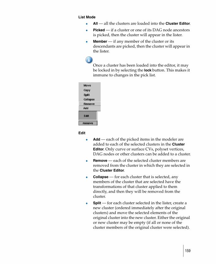
List Mode
◆ All — all the clusters are loaded into the Cluster Editor.
◆ Picked — if a cluster or one of its DAG node ancestors is picked, then the cluster will appear in the lister.
◆ Member — if any member of the cluster or its descendants are picked, then the cluster will appear in the lister.
Once a cluster has been loaded into the editor, it may be locked in by selecting the lock button. This makes it immune to changes in the pick list.
Edit
◆ Add — each of the picked items in the modeler are added to each of the selected clusters in the Cluster Editor. Only curve or surface CVs, polyset vertices, DAG nodes or other clusters can be added to a cluster.
◆ Remove — each of the selected cluster members are removed from the cluster in which they are selected in the Cluster Editor.
◆ Collapse — for each cluster that is selected, any members of the cluster that are selected have the transformations of that cluster applied to them directly, and then they will be removed from the cluster.
◆ Split — for each cluster selected in the lister, create a new cluster (ordered immediately after the original clusters) and move the selected elements of the original cluster into the new cluster. Either the original or new cluster may be empty (if all or none of the cluster members of the original cluster were selected).
159
The new cluster is of the same type as the original (multi or exclusive). Both clusters are grouped under a common DAG node.
◆ Copy — each selected cluster member in the Cluster Editor is added to each of the selected clusters (without removing them from their original clusters). Percentage animation, if it exists, is also copied.
◆ Move — each of the selected cluster members is moved to the selected cluster. Only one cluster can be selected for this operation. The members are removed from the clusters that they are in and placed in the selected cluster.
Other Cluster Editor functionality
A single click a deselected item selects it, and deselects all other items (cluster or member) in the Cluster Editor.
To select multiple items, hold Shift down and click the items you want to select or deselect. Or you can hold Shift and click a deselected item, hold down the mouse button and drag-pick to select a group of items. Starting on a selected item results in unpicking.
Dragging past the ends of the lister scrolls the lister and continue picking or unpicking. Dragging farther past the ends of the window accelerates scrolling.
If only members are selected, then dragging them into another cluster will move the members to the target cluster. The percentage effect on the members is preserved.
160
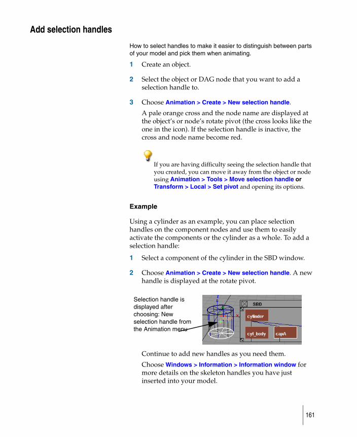
Add selection handles
How to select handles to make it easier to distinguish between parts of your model and pick them when animating.
1 Create an object.
2 Select the object or DAG node that you want to add a selection handle to.
3 Choose Animation > Create > New selection handle.
A pale orange cross and the node name are displayed at the object’s or node’s rotate pivot (the cross looks like the one in the icon). If the selection handle is inactive, the cross and node name become red.
If you are having difficulty seeing the selection handle that you created, you can move it away from the object or node using Animation > Tools > Move selection handle or Transform > Local > Set pivot and opening its options.
Example
Using a cylinder as an example, you can place selection handles on the component nodes and use them to easily activate the components or the cylinder as a whole. To add a selection handle:
1 Select a component of the cylinder in the SBD window.
2 Choose Animation > Create > New selection handle. A new handle is displayed at the rotate pivot.
Continue to add new handles as you need them.
Choose Windows > Information > Information window for more details on the skeleton handles you have just inserted into your model.
Selection handle is displayed after choosing: New selection handle from the Animation menu
161
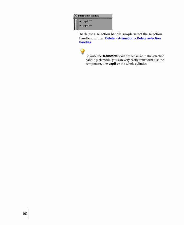
To delete a selection handle simple select the selection handle and then Delete > Animation > Delete selection handles.
Because the Transform tools are sensitive to the selection handle pick mode, you can very easily transform just the component, like capB or the whole cylinder.
162
Change the form of original object in an animation
Set key shape lets you transform one object into another by transforming CVs.
There are two types of interpolations that can be created:
Keyshape
Key shape interpolations are created by animating the CVs of the base object so that they will match the positions of the target object.
ShapeShifter
ShapeShifter interpolations are created by placing the CVs of the base object into clusters, and then providing a method for the amount of transformation to be selected. ShapeShifter interpolations also allow various target shapes to be mixed together.
1 Choose Animation > Tools > Set key shape or select its icon.
The system prompts:Pick the curves or surfaces which are to change shape. Press GO when ready.
2 Pick the curve or surface. The system prompts:Enter a keyframe value(s) for the picked item(s) current shape (last frame set is 0):
3 Type a number and press Enter. The system displays the message:Setting keyframes for 4 CVs of object (curve#2)
You are then prompted to pick the curve or surface to match and set keyframes for these elements.
How to use key shape interpolations1 Begin with an original piece of geometry and copy it as
many times as you like.
2 Manipulate the shape of each copy by applying Transform transformations to the CVs or DAG nodes of each copy.
163
3 When you choose Set key shape, you are prompted to select the curves and surfaces that are to change shape, then to enter keyframe times at which the objects should maintain their original shape.
You are then prompted to select another shape and enter a keyframe time at which the original objects should take on this new shape. Selecting new shapes can continue until all modified copies have been selected and keyframe times are set for them.
4 When you select another shape for the original geometry to assume, the original geometry immediately takes that shape during the selection process and loses its original shape.
If you want to keep the original geometry shapes, copy the original objects before invoking the function, or set a keyframe time for the original shape of the objects, so you can return the objects to their original shapes by viewing that keyframe time.
The key shape animation is created by animating each of the CVs of the original objects. The interpolation between the CVs (the process that transforms one key shape into another) is, by default, a smooth interpolation. You can adjust this interpolation by modifying the tangents of the animation curves of the CVs in the Action Window.
When you complete the key shape animation, you can delete the animation and start again if you are not satisfied with the results. However, before deleting the animation, you may want to restore the original shape of the transforming object. If you typed a keyframe time for the original shape, this is easily done by choosing Animation > Show > View frame and typing the time of that keyframe.
When satisfied with the animation, you can delete the intermediate objects as their shapes are now recorded as keyframes.
How set key shape works
You can use any number of interpolation shapes. Each shape must have identical topology. It is recommended that you copy the original geometry (the geometry shape for the first
164

keyframe), then manipulate the copied geometry into the desired shape for subsequent keyframes. If you are interpolating curve shapes, you can use Curves > New curve and set Knot Spacing to Uniform in the option window to ensure that you create curves with identical topology.
The objects that are used to transform the original object must have the same topology as the original object. Surfaces with same topologies have the same number of CVs in the U and V parametric directions. Curves must have the same number of CVs.
Example
In this example, a sphere is used to create an interpolation animation where the sphere takes on a diamond shape through 10 keyframes, then reverts to its original shape through another 10 keyframes, and back to the diamond in another 10 keyframes.
Place two spheres
1 Choose Surfaces > Primitives > Sphere and place a sphere in the Front window at -5,0,0.
2 Place another sphere at 3,0.0. Both of these pieces of geometry are identical in topology.
Scale and move the spheres
1 With the second sphere active, choose Transform > Scale and type 4 to scale the sphere to a value of 4 units.
2 Choose ObjectDisplay > Control ❒ and make sure the CVs is toggled ON (indicated by a check mark). Press GO.
3 Pick nothing to ensure that no geometry is active, then choose Pick > Point Types > CV and using the bounding box technique, select only the first row of CVs along the top of the second sphere.
4 When the CVs are active, choose Transform > Move and use the right mouse button to move these CVs upwards along the Z-axis to elongate the top of the sphere into a pointed shape.
165
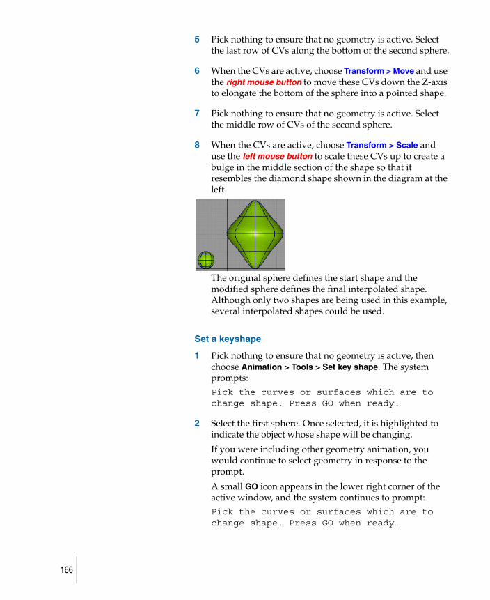
5 Pick nothing to ensure that no geometry is active. Select the last row of CVs along the bottom of the second sphere.
6 When the CVs are active, choose Transform > Move and use the right mouse button to move these CVs down the Z-axis to elongate the bottom of the sphere into a pointed shape.
7 Pick nothing to ensure that no geometry is active. Select the middle row of CVs of the second sphere.
8 When the CVs are active, choose Transform > Scale and use the left mouse button to scale these CVs up to create a bulge in the middle section of the shape so that it resembles the diamond shape shown in the diagram at the left.
The original sphere defines the start shape and the modified sphere defines the final interpolated shape. Although only two shapes are being used in this example, several interpolated shapes could be used.
Set a keyshape
1 Pick nothing to ensure that no geometry is active, then choose Animation > Tools > Set key shape. The system prompts:Pick the curves or surfaces which are to change shape. Press GO when ready.
2 Select the first sphere. Once selected, it is highlighted to indicate the object whose shape will be changing.
If you were including other geometry animation, you would continue to select geometry in response to the prompt.
A small GO icon appears in the lower right corner of the active window, and the system continues to prompt:Pick the curves or surfaces which are to change shape. Press GO when ready.
166
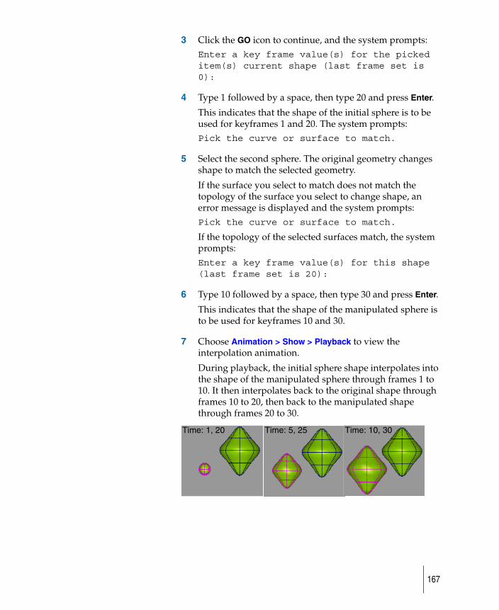
3 Click the GO icon to continue, and the system prompts:Enter a key frame value(s) for the picked item(s) current shape (last frame set is 0):
4 Type 1 followed by a space, then type 20 and press Enter.
This indicates that the shape of the initial sphere is to be used for keyframes 1 and 20. The system prompts:Pick the curve or surface to match.
5 Select the second sphere. The original geometry changes shape to match the selected geometry.
If the surface you select to match does not match the topology of the surface you select to change shape, an error message is displayed and the system prompts: Pick the curve or surface to match.
If the topology of the selected surfaces match, the system prompts:Enter a key frame value(s) for this shape (last frame set is 20):
6 Type 10 followed by a space, then type 30 and press Enter.
This indicates that the shape of the manipulated sphere is to be used for keyframes 10 and 30.
7 Choose Animation > Show > Playback to view the interpolation animation.
During playback, the initial sphere shape interpolates into the shape of the manipulated sphere through frames 1 to 10. It then interpolates back to the original shape through frames 10 to 20, then back to the manipulated shape through frames 20 to 30.
Time: 1, 20 Time: 5, 25 Time: 10, 30
167
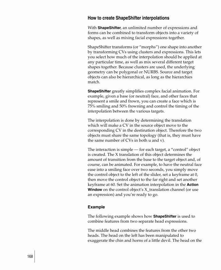
How to create ShapeShifter interpolations
With ShapeShifter, an unlimited number of expressions and forms can be combined to transform objects into a variety of shapes, as well as mixing facial expressions together.
ShapeShifter transforms (or “morphs”) one shape into another by transforming CVs using clusters and expressions. This lets you select how much of the interpolation should be applied at any particular time, as well as mix several different target shapes together. Because clusters are used, the underlying geometry can be polygonal or NURBS. Source and target objects can also be hierarchical, as long as the hierarchies match.
ShapeShifter greatly simplifies complex facial animation. For example, given a base (or neutral) face, and other faces that represent a smile and frown, you can create a face which is 75% smiling and 50% frowning and control the timing of the interpolation between the various targets.
The interpolation is done by determining the translation which will make a CV in the source object move to the corresponding CV in the destination object. Therefore the two objects must share the same topology (that is, they must have the same number of CVs in both u and v).
The interaction is simple — for each target, a “control” object is created. The X translation of this object determines the amount of transition from the base to the target object and, of course, can be animated. For example, to have the neutral face ease into a smiling face over two seconds, you simply move the control object to the left of the slider, set a keyframe at 0, then move the control object to the far right and set another keyframe at 60. Set the animation interpolation in the Action Window on the control object’s X_translation channel (or use an expression) and you’re ready to go.
Example
The following example shows how ShapeShifter is used to combine features from two separate head expressions.
The middle head combines the features from the other two heads. The head on the left has been manipulated to exaggerate the chin and horns of a little devil. The head on the
168
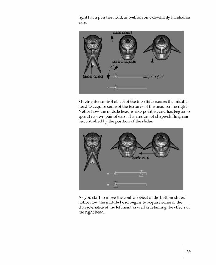
right has a pointier head, as well as some devilishly handsome ears.
Moving the control object of the top slider causes the middle head to acquire some of the features of the head on the right. Notice how the middle head is also pointier, and has begun to sprout its own pair of ears. The amount of shape-shifting can be controlled by the position of the slider.
As you start to move the control object of the bottom slider, notice how the middle head begins to acquire some of the characteristics of the left head as well as retaining the effects of the right head.
target object target object
base object
control objects
apply ears
169
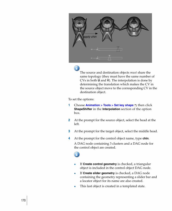
The source and destination objects must share the same topology (they must have the same number of CVs in both U and V). The interpolation is done by determining the translation which makes the CV in the source object move to the corresponding CV in the destination object.
To set the options:
1 Choose Animation > Tools > Set key shape ❒, then click ShapeShifter in the Interpolation section of the option box.
2 At the prompt for the source object, select the head at the left.
3 At the prompt for the target object, select the middle head.
4 At the prompt for the control object name, type chin.
A DAG node containing 3 clusters and a DAG node for the control object are created.
◆ If Create control geometry is checked, a triangular object is included in the control object DAG node.
◆ If Create slider geometry is checked, a DAG node containing the geometry representing a slider bar and a locator object for its name are also created.
◆ This last object is created in a templated state.
apply chin
170
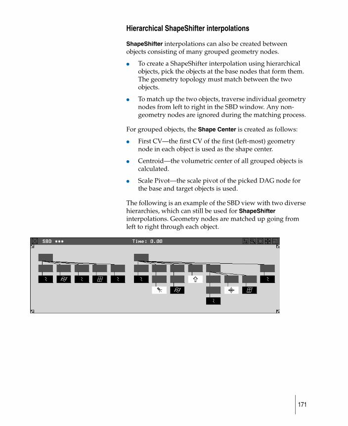
Hierarchical ShapeShifter interpolations
ShapeShifter interpolations can also be created between objects consisting of many grouped geometry nodes.
● To create a ShapeShifter interpolation using hierarchical objects, pick the objects at the base nodes that form them. The geometry topology must match between the two objects.
● To match up the two objects, traverse individual geometry nodes from left to right in the SBD window. Any non-geometry nodes are ignored during the matching process.
For grouped objects, the Shape Center is created as follows:
● First CV—the first CV of the first (left-most) geometry node in each object is used as the shape center.
● Centroid—the volumetric center of all grouped objects is calculated.
● Scale Pivot—the scale pivot of the picked DAG node for the base and target objects is used.
The following is an example of the SBD view with two diverse hierarchies, which can still be used for ShapeShifter interpolations. Geometry nodes are matched up going from left to right through each object.
171
Create clusters with properties for deformation
The Deformation Control window lets you set parameters for a deformation frame, then attach that deformation frame to an object. For a Curve, Axis, Skeleton, or Character Builder deformation, once the deformation frame has been attached to the object, the surface of the object can be modified interactively by manipulating the deformation frame.
Understanding when to use deformation
When an object is required to change shape, the CVs controlling the surface shape can be modified, usually one CV at a time. This gives you flexibility when changing the shape of an object, but it quickly becomes tedious and time consuming when a surface or object is constructed from many CVs.
Deformation control provides a higher level of manipulating CVs by letting you create groups (or clusters) of CVs. It’s like pushing and pulling on the surface, as in clay modeling.
There are four types of deformation frames:
• Axis Frame• Curve Frame• Skeleton Frame• Character Builder Frame
To attach a deformation frame to a model, the Deformation Control window should be displayed on the screen. Once a deformation frame has been attached to the model, the window can be closed.
Deformation control tools do not work on instanced objects. This is because deformations are achieved through clusters, and clusters apply to the CVs of objects. Instances share the same CVs as the object they instance, and so the deformation can not be distributed across instances.
Deformation control tools do not work on objects with construction history. This is because construction history already controls the shape of the object.
172
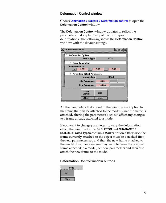
Deformation Control window
Choose Animation > Editors > Deformation control to open the Deformation Control window.
The Deformation Control window updates to reflect the parameters that apply to any of the four types of deformations. The following shows the Deformation Control window with the default settings.
All the parameters that are set in the window are applied to the frame that will be attached to the model. Once the frame is attached, altering the parameters does not affect any changes to a frame already attached to a model.
If you want to change parameters to vary the deformation effect, the window for the SKELETON and CHARACTER BUILDER Frame Types contain a Modify option. Otherwise, the frame currently attached to the object must be detached first, the new parameters set, and then the new frame attached to the model. In some cases you may want to leave the original frame attached to a model, set new parameters and then also attach the new frame to the model.
Deformation Control window buttons
173
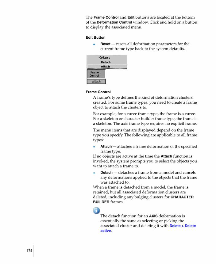
The Frame Control and Edit buttons are located at the bottom of the Deformation Control window. Click and hold on a button to display the associated menu.
Edit Button
◆ Reset — resets all deformation parameters for the current frame type back to the system defaults.
Frame Control
A frame’s type defines the kind of deformation clusters created. For some frame types, you need to create a frame object to attach the clusters to.
For example, for a curve frame type, the frame is a curve. For a skeleton or character builder frame type, the frame is a skeleton. The axis frame type requires no explicit frame.
The menu items that are displayed depend on the frame type you specify. The following are applicable to all frame types:
◆ Attach — attaches a frame deformation of the specified frame type.
If no objects are active at the time the Attach function is invoked, the system prompts you to select the objects you want to attach a frame to.
◆ Detach — detaches a frame from a model and cancels any deformations applied to the objects that the frame was attached to.
When a frame is detached from a model, the frame is retained, but all associated deformation clusters are deleted, including any bulging clusters for CHARACTER BUILDER frames.
The detach function for an AXIS deformation is essentially the same as selecting or picking the associated cluster and deleting it with Delete > Delete active.
174
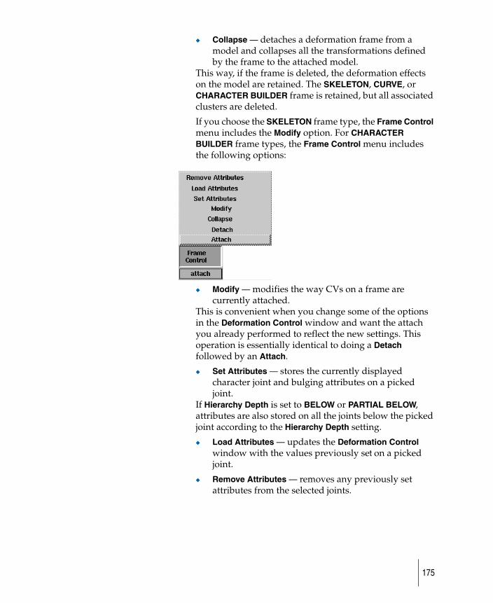
◆ Collapse — detaches a deformation frame from a model and collapses all the transformations defined by the frame to the attached model.
This way, if the frame is deleted, the deformation effects on the model are retained. The SKELETON, CURVE, or CHARACTER BUILDER frame is retained, but all associated clusters are deleted.
If you choose the SKELETON frame type, the Frame Control menu includes the Modify option. For CHARACTER BUILDER frame types, the Frame Control menu includes the following options:
◆ Modify — modifies the way CVs on a frame are currently attached.
This is convenient when you change some of the options in the Deformation Control window and want the attach you already performed to reflect the new settings. This operation is essentially identical to doing a Detach followed by an Attach.
◆ Set Attributes — stores the currently displayed character joint and bulging attributes on a picked joint.
If Hierarchy Depth is set to BELOW or PARTIAL BELOW, attributes are also stored on all the joints below the picked joint according to the Hierarchy Depth setting.
◆ Load Attributes — updates the Deformation Control window with the values previously set on a picked joint.
◆ Remove Attributes — removes any previously set attributes from the selected joints.
175
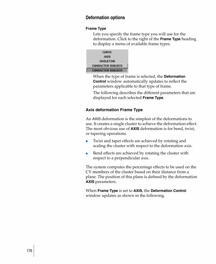
Deformation options
Frame Type
Lets you specify the frame type you will use for the deformation. Click to the right of the Frame Type heading to display a menu of available frame types.
When the type of frame is selected, the Deformation Control window automatically updates to reflect the parameters applicable to that type of frame.
The following describes the different parameters that are displayed for each selected Frame Type.
Axis deformation Frame Type
An AXIS deformation is the simplest of the deformations to use. It creates a single cluster to achieve the deformation effect. The most obvious use of AXIS deformation is for bend, twist, or tapering operations.
● Twist and taper effects are achieved by rotating and scaling the cluster with respect to the deformation axis.
● Bend effects are achieved by rotating the cluster with respect to a perpendicular axis.
The system computes the percentage effects to be used on the CV members of the cluster based on their distance from a plane. The position of this plane is defined by the deformation AXIS parameters.
When Frame Type is set to AXIS, the Deformation Control window updates as shown in the following.
176

Frame Parameters
Deformation Axis
The Deformation Axis parameters are used to specify the direction in which the percentage effects will change.
Click and drag at the bottom of these sliders to select a value, or click to type a new value then press Enter.
The interpolation distance is computed as the world space distance between the object’s CV and a plane that is normal to the deformation axis. The origin of this plane is computed by projecting a bounding box in the axis direction and finding the point at which there will be 0% effect. The easiest way to picture this is to imagine a cylinder as the deforming object. The deformation axis lies in the direction of the long axis of the cylinder. The origin will be at the center of the bottom of the cylinder when the percentage range is 0.00 to 100.00. Each of the Deformation Axis parameters are editable and any deformation axis can be specified.
Percentage Effect Parameters
The Percentage Effect Parameters for Interpolation and the Min/Max Percentage values are the same for the AXIS and CURVE frame types.
177
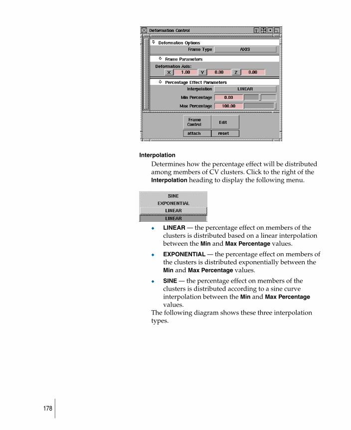
Interpolation
Determines how the percentage effect will be distributed among members of CV clusters. Click to the right of the Interpolation heading to display the following menu.
◆ LINEAR — the percentage effect on members of the clusters is distributed based on a linear interpolation between the Min and Max Percentage values.
◆ EXPONENTIAL — the percentage effect on members of the clusters is distributed exponentially between the Min and Max Percentage values.
◆ SINE — the percentage effect on members of the clusters is distributed according to a sine curve interpolation between the Min and Max Percentage values.
The following diagram shows these three interpolation types.
178
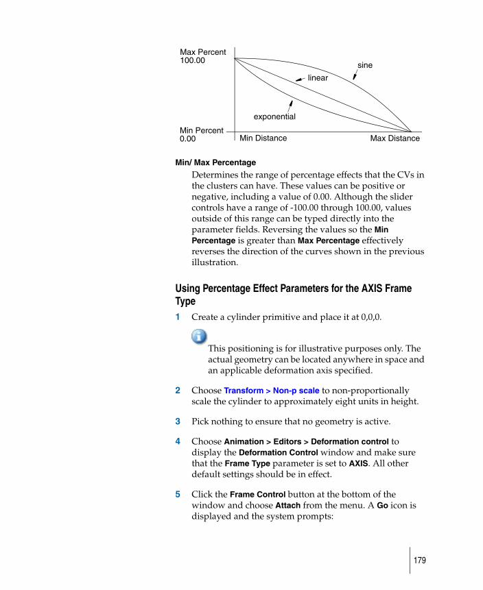
Min/ Max Percentage
Determines the range of percentage effects that the CVs in the clusters can have. These values can be positive or negative, including a value of 0.00. Although the slider controls have a range of -100.00 through 100.00, values outside of this range can be typed directly into the parameter fields. Reversing the values so the Min Percentage is greater than Max Percentage effectively reverses the direction of the curves shown in the previous illustration.
Using Percentage Effect Parameters for the AXIS Frame Type1 Create a cylinder primitive and place it at 0,0,0.
This positioning is for illustrative purposes only. The actual geometry can be located anywhere in space and an applicable deformation axis specified.
2 Choose Transform > Non-p scale to non-proportionally scale the cylinder to approximately eight units in height.
3 Pick nothing to ensure that no geometry is active.
4 Choose Animation > Editors > Deformation control to display the Deformation Control window and make sure that the Frame Type parameter is set to AXIS. All other default settings should be in effect.
5 Click the Frame Control button at the bottom of the window and choose Attach from the menu. A Go icon is displayed and the system prompts:
sine
linear
exponential
Min Percent0.00
Max Percent100.00
Min Distance Max Distance
179
Pick uninstanced surface(s) to deform, then GO.
6 Select the surfaces you want to deform. Once selected, the surfaces are highlighted.
7 When all the surfaces you want to deform are selected, click GO. The system responds with a prompt indicating that it is creating an axis deformation.
Once the prompt clears, the axis deformation frame has been attached to the active objects (the cylinder in this example).
Transforming the cluster1 Choose Transform > Rotate and use the middle mouse
button to rotate along the Y axis. Take note of the effect on the surface. Try other axis rotations and scale functions to experiment.
2 Pick nothing to ensure that no geometry is active.
3 Choose Animation > Pick > Cluster and select any CV on the surface of the model to select the cluster.
Clusters can also be selected directly in the SBD window using either Pick > Object or Animation > Pick > Cluster.
4 Choose Delete > Delete active to delete the active cluster, returning the model to its original state.
More to try
● With the axis frame detached, repeat the steps and vary the Min and Max Percentage values as shown in the following.
● With the previous axis frame detached, repeat the steps again, varying the Min and Max Percentage values as shown in the following.
You can also try a Min Percentage value of 100 and a Max Percentage value of 100.
-
180
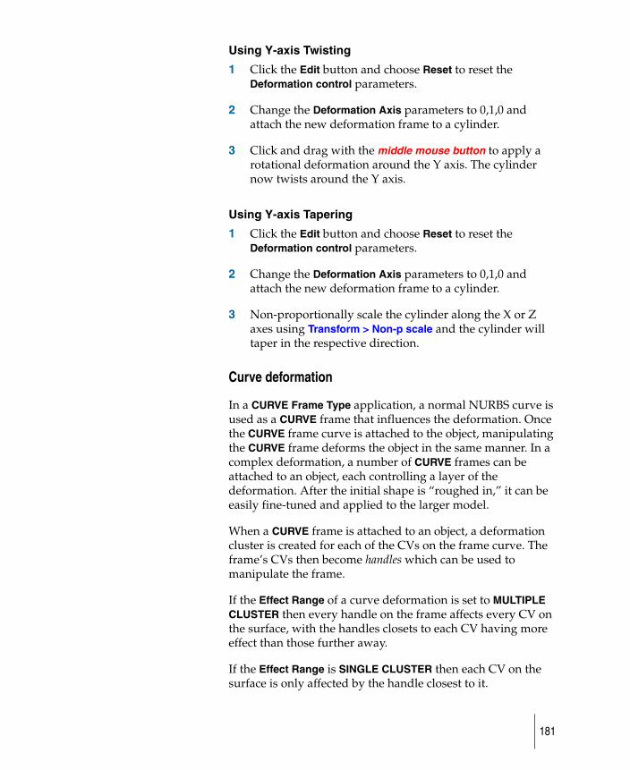
Using Y-axis Twisting
1 Click the Edit button and choose Reset to reset the Deformation control parameters.
2 Change the Deformation Axis parameters to 0,1,0 and attach the new deformation frame to a cylinder.
3 Click and drag with the middle mouse button to apply a rotational deformation around the Y axis. The cylinder now twists around the Y axis.
Using Y-axis Tapering
1 Click the Edit button and choose Reset to reset the Deformation control parameters.
2 Change the Deformation Axis parameters to 0,1,0 and attach the new deformation frame to a cylinder.
3 Non-proportionally scale the cylinder along the X or Z axes using Transform > Non-p scale and the cylinder will taper in the respective direction.
Curve deformation
In a CURVE Frame Type application, a normal NURBS curve is used as a CURVE frame that influences the deformation. Once the CURVE frame curve is attached to the object, manipulating the CURVE frame deforms the object in the same manner. In a complex deformation, a number of CURVE frames can be attached to an object, each controlling a layer of the deformation. After the initial shape is “roughed in,” it can be easily fine-tuned and applied to the larger model.
When a CURVE frame is attached to an object, a deformation cluster is created for each of the CVs on the frame curve. The frame’s CVs then become handles which can be used to manipulate the frame.
If the Effect Range of a curve deformation is set to MULTIPLE CLUSTER then every handle on the frame affects every CV on the surface, with the handles closets to each CV having more effect than those further away.
If the Effect Range is SINGLE CLUSTER then each CV on the surface is only affected by the handle closest to it.
181
Examples
This example shows the original surface, and then the duplicated curve from the surface generated by the CURVE Frame Type. To create the clusters, each handle on the Curve frame is matched with one or more CVs on the surface. When the Effect Range option is set to SINGLE CLUSTER, the match is determined by matching the surface CVs with the closest frame CV in world space.
In this example, the CURVE Frame Type is a free-form curve with seven CVs. Three of them are not as close to a CV than the other four. As a result, three null clusters are created. They are displayed in the SBD window, but have no effect on the surface.
x x x x
x x x x
x x x x
x x x x
cluster 1
cluster 2
cluster 3
cluster 4 x
x
x
x
CURVE Frame Type is a
x x x x
x x x x
x x x x
x x x x
Original surface: Surface with duplicated curve:
duplicated curve from the surface.
182
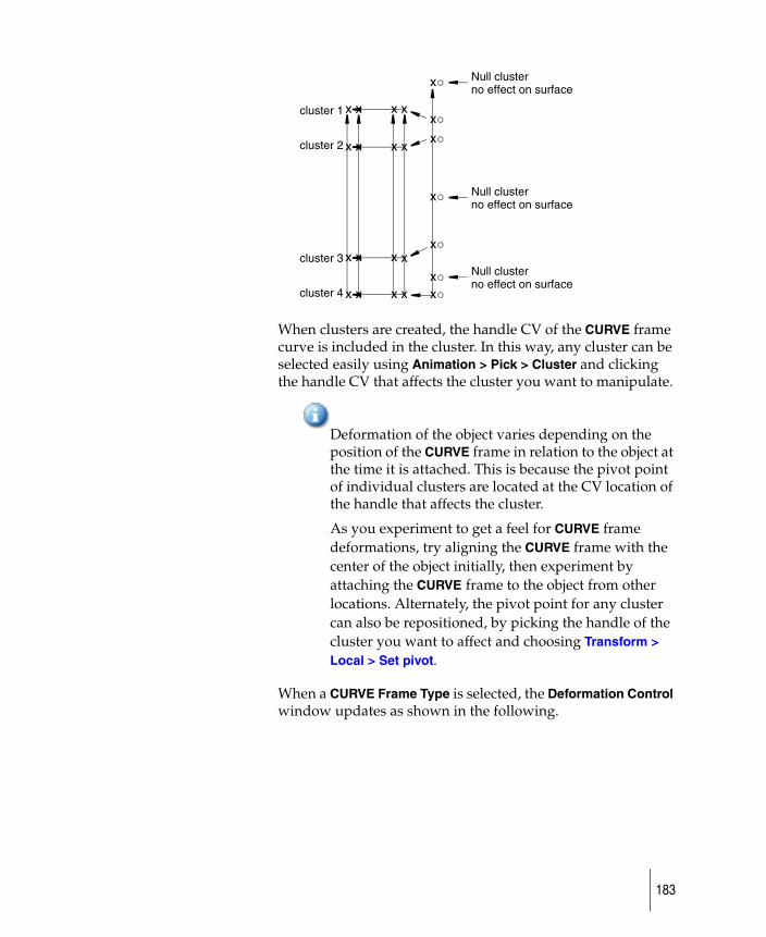
When clusters are created, the handle CV of the CURVE frame curve is included in the cluster. In this way, any cluster can be selected easily using Animation > Pick > Cluster and clicking the handle CV that affects the cluster you want to manipulate.
Deformation of the object varies depending on the position of the CURVE frame in relation to the object at the time it is attached. This is because the pivot point of individual clusters are located at the CV location of the handle that affects the cluster.
As you experiment to get a feel for CURVE frame deformations, try aligning the CURVE frame with the center of the object initially, then experiment by attaching the CURVE frame to the object from other locations. Alternately, the pivot point for any cluster can also be repositioned, by picking the handle of the cluster you want to affect and choosing Transform > Local > Set pivot.
When a CURVE Frame Type is selected, the Deformation Control window updates as shown in the following.
x x x x
x x x x
x x x x
x x x x
cluster 1
cluster 2
cluster 3
cluster 4 x
x
x
x
x
x
x
Null clusterno effect on surface
Null clusterno effect on surface
Null clusterno effect on surface
183
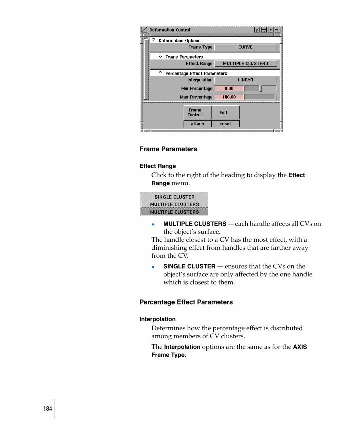
Frame Parameters
Effect Range
Click to the right of the heading to display the Effect Range menu.
◆ MULTIPLE CLUSTERS — each handle affects all CVs on the object’s surface.
The handle closest to a CV has the most effect, with a diminishing effect from handles that are farther away from the CV.
◆ SINGLE CLUSTER — ensures that the CVs on the object’s surface are only affected by the one handle which is closest to them.
Percentage Effect Parameters
Interpolation
Determines how the percentage effect is distributed among members of CV clusters.
The Interpolation options are the same as for the AXIS Frame Type.
184
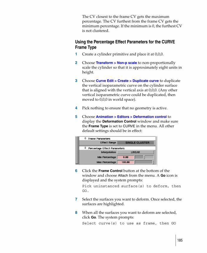
The CV closest to the frame CV gets the maximum percentage. The CV furthest from the frame CV gets the minimum percentage. If the minimum is 0, the furthest CV is not clustered.
Using the Percentage Effect Parameters for the CURVE Frame Type1 Create a cylinder primitive and place it at 0,0,0.
2 Choose Transform > Non-p scale to non-proportionally scale the cylinder so that it is approximately eight units in height.
3 Choose Curve Edit > Create > Duplicate curve to duplicate the vertical isoparametric curve on the cylinder surface that is aligned with the vertical axis at 0,0,0. (Any other vertical isoparametric curve could be duplicated, then moved to 0,0,0 in world space).
4 Pick nothing to ensure that no geometry is active.
5 Choose Animation > Editors > Deformation control to display the Deformation Control window and make sure the Frame Type is set to CURVE in the menu. All other default settings should be in effect:
6 Click the Frame Control button at the bottom of the window and choose Attach from the menu. A Go icon is displayed and the system prompts:Pick uninstanced surface(s) to deform, then GO.
7 Select the surfaces you want to deform. Once selected, the surfaces are highlighted.
8 When all the surfaces you want to deform are selected, click Go. The system prompts:Select curve(s) to use as frame, then GO
SINGLE CLUSTER
185
Select the curves you want to use as the frames, (the duplicated isoparametric curve in this case). Once selected, the curves are highlighted.
9 Click Go, then pick nothing to ensure that no geometry is active.
10 Choose Pick > Object and drag a pick box over at least part of the cylinder surface and the CURVE frame curve to make both objects active, then click directly on an edge of the cylinder surface to deselect it to make only the CURVE frame curve active.
Transforming the cluster
The CURVE frame can be moved anywhere once it has been attached to the object, and the pivot points for the clusters remain in the location where the CURVE frame was originally created. Although the pivot points for any individual cluster can be set anywhere at any time, this is an easy way to align them at the center of a cluster. To always maintain the frame and object in their relative positions, simply group them together.
1 Choose Transform > Move and use the middle mouse button to move the CURVE frame curve off to the right side of the cylinder surface, where it will be easier to manipulate.
2 Pick nothing to ensure that no geometry is active.
3 Choose Animation > Pick > Cluster and select the CV attached to the second handle from the top of the CURVE frame curve.
Once the cluster is selected, the handle is highlighted as well as all CVs that this handle controls.
4 Choose Transform > Scale and use the left mouse button to scale the cluster up to deform the surface.
Observe the effect of the deformation in the other modeling windows. All CVs in the clusters are an equal distance from the frame, therefore there is no percentage effect difference between the CVs.
186
Detaching the Curve frame1 Pick nothing to ensure that no geometry is active.
2 Click the Frame Control button at the bottom of the Deformation Control window and choose Detach from the menu.
The system prompts:Pick frame(s) to detach, the GO
3 Select the CURVE frames to be detached from their respective objects. As a CURVE frame is selected, it is highlighted.
4 When the frames you want to detach are selected, click Go to proceed with the Detach operation.
5 Once Go is clicked, the selected frames are detached from the objects to which they were attached and the objects themselves return to their original shape. The original CURVE Frame curve is retained.
More to try1 Leave the CURVE frame curve in its current location off to
the side of the cylinder surface and reattach it to the cylinder again.
2 Make sure that no geometry is active, choose Animation > Pick > Cluster and select a CV attached to the second handle from the top of the CURVE frame curve.
Once the cluster is selected, the handle is highlighted as well as all CVs that this handle controls.
3 Choose Transform > Scale and use the left mouse button to scale the cluster up to deform the surface.
Notice how the percentage effect of the scale ranges from a Min Percentage of 0 to 100 around the periphery of the cylinder because all CVs are no longer an equal distance from the frame curve.
4 Detach the CURVE frame from the cylinder, returning the cylinder to its original shape.
5 Attach the CURVE frame to the cylinder again.
187
6 Select individual handles and use Transform > Move to deform the surface. Experiment with Transform > Rotate and Transform > Non-p scale.
Keep in mind that if you achieve an effect that you want to retain and no longer need the clusters, the CURVE frame can be detached from the object without the object losing its deformation transformations by choosing Collapse from the Frame Control menu.
Additional tips
◆ Interaction with the system can be sped up significantly when using CURVE frames, by toggling the original geometry to which the CURVE frame is attached to an invisible state.
◆ If the same CURVE frame curve is attached to more than one object, the frame handles do not change appearance in any way to indicate that the frame is attached to multiple objects. Therefore, take care that the proper clusters are being selected when you select the handle.
◆ If any objects are active at the time the Deformation control function is invoked, the system interprets these surfaces to be the surfaces which you want to attach a frame to. If this happens, you will not be prompted to select the surfaces to attach a frame to.
◆ If a handle CV is removed from the cluster it controls, the cluster remains but that handle is no longer selectable and has no effect on the cluster.
Creating shearing effects
A shearing effect can be simulated using either of the following deformation techniques.
● Create an AXIS deformation along the desired shearing axis using a linear Interpolation value and then use Transform > Move to manipulate the resulting cluster.
● Create a CURVE frame deformation along the desired shearing axis using a two point polyline as the curve and MULTIPLE CLUSTERS and LINEAR parameter settings. Choose Transform > Move to manipulate the resulting frame to create the shear.
188
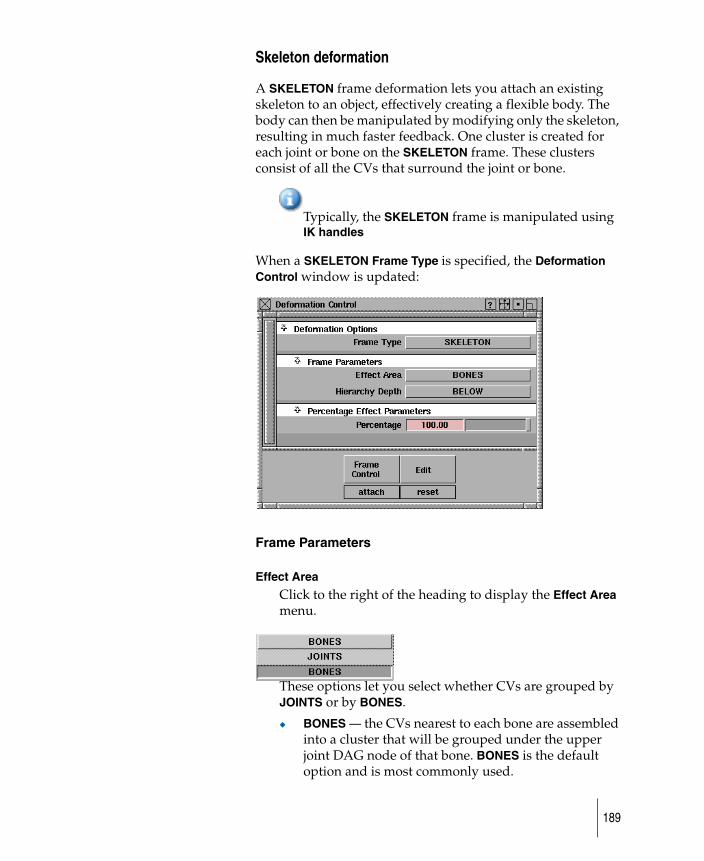
Skeleton deformation
A SKELETON frame deformation lets you attach an existing skeleton to an object, effectively creating a flexible body. The body can then be manipulated by modifying only the skeleton, resulting in much faster feedback. One cluster is created for each joint or bone on the SKELETON frame. These clusters consist of all the CVs that surround the joint or bone.
Typically, the SKELETON frame is manipulated using IK handles
When a SKELETON Frame Type is specified, the Deformation Control window is updated:
Frame Parameters
Effect Area
Click to the right of the heading to display the Effect Area menu.
These options let you select whether CVs are grouped by JOINTS or by BONES.
◆ BONES — the CVs nearest to each bone are assembled into a cluster that will be grouped under the upper joint DAG node of that bone. BONES is the default option and is most commonly used.
189
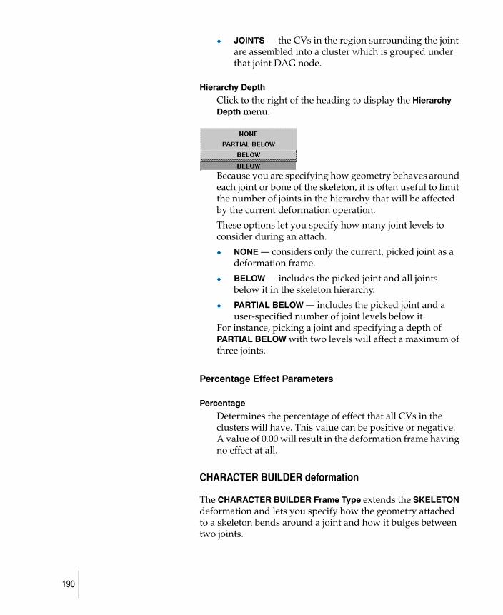
◆ JOINTS — the CVs in the region surrounding the joint are assembled into a cluster which is grouped under that joint DAG node.
Hierarchy Depth
Click to the right of the heading to display the Hierarchy Depth menu.
Because you are specifying how geometry behaves around each joint or bone of the skeleton, it is often useful to limit the number of joints in the hierarchy that will be affected by the current deformation operation.
These options let you specify how many joint levels to consider during an attach.
◆ NONE — considers only the current, picked joint as a deformation frame.
◆ BELOW — includes the picked joint and all joints below it in the skeleton hierarchy.
◆ PARTIAL BELOW — includes the picked joint and a user-specified number of joint levels below it.
For instance, picking a joint and specifying a depth of PARTIAL BELOW with two levels will affect a maximum of three joints.
Percentage Effect Parameters
Percentage
Determines the percentage of effect that all CVs in the clusters will have. This value can be positive or negative. A value of 0.00 will result in the deformation frame having no effect at all.
CHARACTER BUILDER deformation
The CHARACTER BUILDER Frame Type extends the SKELETON deformation and lets you specify how the geometry attached to a skeleton bends around a joint and how it bulges between two joints.
190
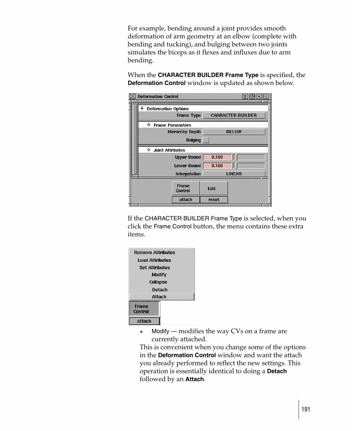
For example, bending around a joint provides smooth deformation of arm geometry at an elbow (complete with bending and tucking), and bulging between two joints simulates the biceps as it flexes and influxes due to arm bending.
When the CHARACTER BUILDER Frame Type is specified, the Deformation Control window is updated as shown below.
If the CHARACTER BUILDER Frame Type is selected, when you click the Frame Control button, the menu contains these extra items.
◆ Modify — modifies the way CVs on a frame are currently attached.
This is convenient when you change some of the options in the Deformation Control window and want the attach you already performed to reflect the new settings. This operation is essentially identical to doing a Detach followed by an Attach.
191
The Modify operation in the Character Builder may not work correctly if the Skeleton hierarchy has been used in multiple Attach operations, or if the hierarchy to be modified encompasses a larger hierarchy than was used in Attach.
In Animation > Editors > Deformation Control, do the Modify operation on only one part of the skeleton at a time if all of the following conditions exist:
You use Frame Control > Attach with the Hierarchy option set on the upper part of the skeleton
You then do another Frame Control > Attach with Hierarchy set on the lower part of a skeleton
At least one joint belongs to both hierarchies.
◆ Set Attributes — stores the currently displayed character joint and bulging attributes on a picked joint.
If Hierarchy Depth is set to BELOW or PARTIAL BELOW, attributes are also stored on the joints below the picked joint according to the Hierarchy Depth setting.
◆ Load Attributes — updates the Deformation Control window with the values previously set on a picked joint.
◆ Remove Attributes — removes any previously set attributes from the selected joints.
Frame Parameters
Hierarchy Depth
These options are the same as for the SKELETON Frame Type and let you specify how many joint levels to consider during an attach. See Skeleton Deformation for details.
Bulging
This toggle indicates whether bulging effects should be applied to the joints in the selected hierarchy. Bulging on a joint means that bulging clusters are created for the geometry between that joint and the next lower joint.
192
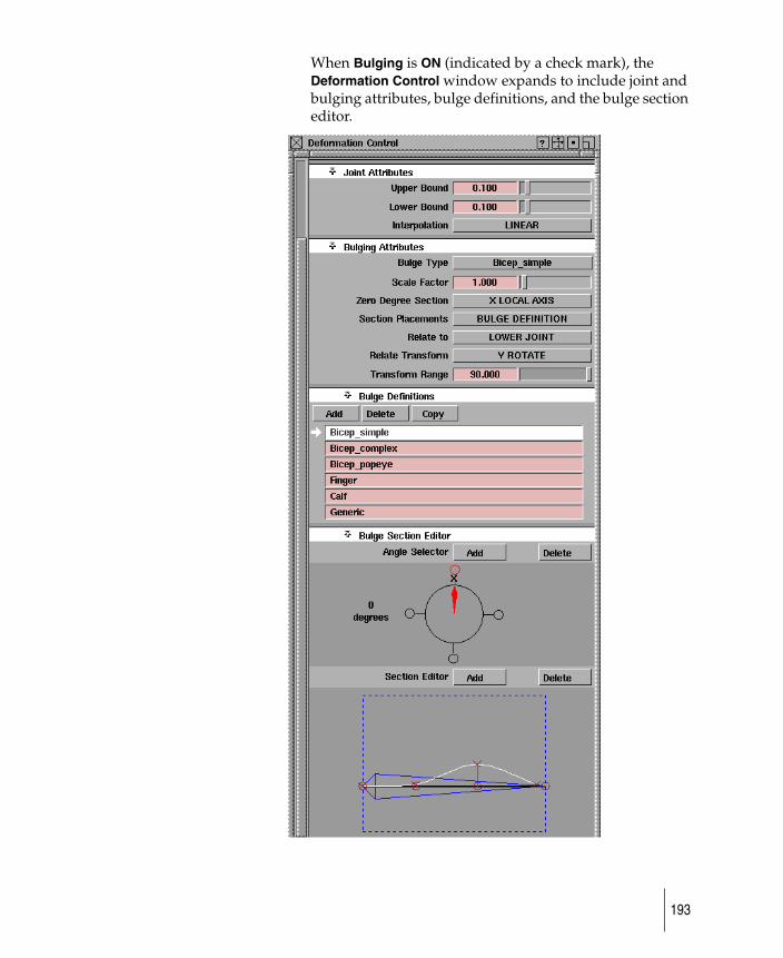
When Bulging is ON (indicated by a check mark), the Deformation Control window expands to include joint and bulging attributes, bulge definitions, and the bulge section editor.
193
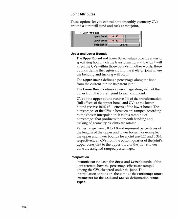
Joint Attributes
These options let you control how smoothly geometry CVs around a joint will bend and tuck at that joint.
Upper and Lower Bounds
The Upper Bound and Lower Bound values provide a way of specifying how much the transformations at the joint will affect the CVs within those bounds. In other words, these bounds define the region around the skeleton joint where the bending and tucking will occur.
The Upper Bound defines a percentage along the bone from the current joint to its parent joint.
The Lower Bound defines a percentage along each of the bones from the current joint to each child joint.
CVs at the upper bound receive 0% of the transformation (full effects of the upper bone) and CVs at the lower bound receive 100% (full effects of the lower bone). The percentages of the CVs in between are ramped according to the chosen interpolation. It is this ramping of percentages that produces the smooth bending and tucking of geometry as joints are rotated.
Values range from 0.0 to 1.0 and represent percentages of the lengths of the upper and lower bones. For example, if the upper and lower bounds for a joint are 0.25 and 0.333, respectively, all CVs from the bottom quarter of the joint’s upper bone joint to the upper third of the joint’s lower bone are assigned ramped percentages.
Interpolation
Interpolation between the Upper and Lower bounds of the joint refers to how the percentage effects are ramped among the CVs clustered under the joint. The interpolation options are the same as the Percentage Effect Parameters for the AXIS and CURVE deformation Frame Types.
194
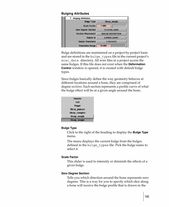
Bulging Attributes
Bulge definitions are maintained on a project-by-project basis and are stored in the bulge_types file in the current project’s misc_data directory. All wire files in a project access the same bulges. If this file does not exist when the Deformation Control window is opened, it is created with default bulge types.
Since bulges basically define the way geometry behaves at different locations around a bone, they are comprised of degree sections. Each section represents a profile curve of what the bulge effect will be at a given angle around the bone.
Bulge Type
Click to the right of the heading to display the Bulge Type menu.
The menu displays the current bulge from the bulges defined in the bulge_types file. Pick the bulge name to select it.
Scale Factor
This slider is used to intensify or diminish the effects of a given bulge.
Zero Degree Section
Tells you which direction around the bone represents zero degrees. This is a way for you to specify which slice along a bone will receive the bulge profile that is drawn in the
195
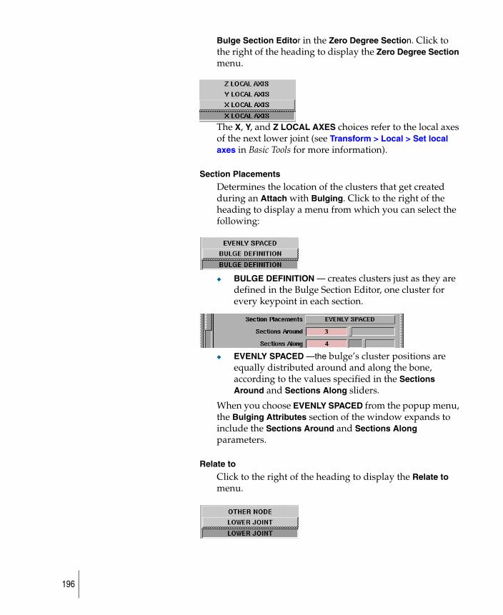
Bulge Section Editor in the Zero Degree Section. Click to the right of the heading to display the Zero Degree Section menu.
The X, Y, and Z LOCAL AXES choices refer to the local axes of the next lower joint (see Transform > Local > Set local axes in Basic Tools for more information).
Section Placements
Determines the location of the clusters that get created during an Attach with Bulging. Click to the right of the heading to display a menu from which you can select the following:
◆ BULGE DEFINITION — creates clusters just as they are defined in the Bulge Section Editor, one cluster for every keypoint in each section.
◆ EVENLY SPACED —the bulge’s cluster positions are equally distributed around and along the bone, according to the values specified in the Sections Around and Sections Along sliders.
When you choose EVENLY SPACED from the popup menu, the Bulging Attributes section of the window expands to include the Sections Around and Sections Along parameters.
Relate to
Click to the right of the heading to display the Relate to menu.
196
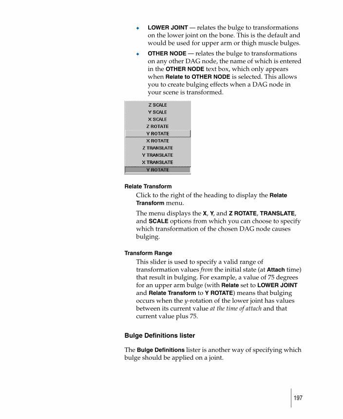
◆ LOWER JOINT — relates the bulge to transformations on the lower joint on the bone. This is the default and would be used for upper arm or thigh muscle bulges.
◆ OTHER NODE — relates the bulge to transformations on any other DAG node, the name of which is entered in the OTHER NODE text box, which only appears when Relate to OTHER NODE is selected. This allows you to create bulging effects when a DAG node in your scene is transformed.
Relate Transform
Click to the right of the heading to display the Relate Transform menu.
The menu displays the X, Y, and Z ROTATE, TRANSLATE, and SCALE options from which you can choose to specify which transformation of the chosen DAG node causes bulging.
Transform Range
This slider is used to specify a valid range of transformation values from the initial state (at Attach time) that result in bulging. For example, a value of 75 degrees for an upper arm bulge (with Relate set to LOWER JOINT and Relate Transform to Y ROTATE) means that bulging occurs when the y-rotation of the lower joint has values between its current value at the time of attach and that current value plus 75.
Bulge Definitions lister
The Bulge Definitions lister is another way of specifying which bulge should be applied on a joint.
197
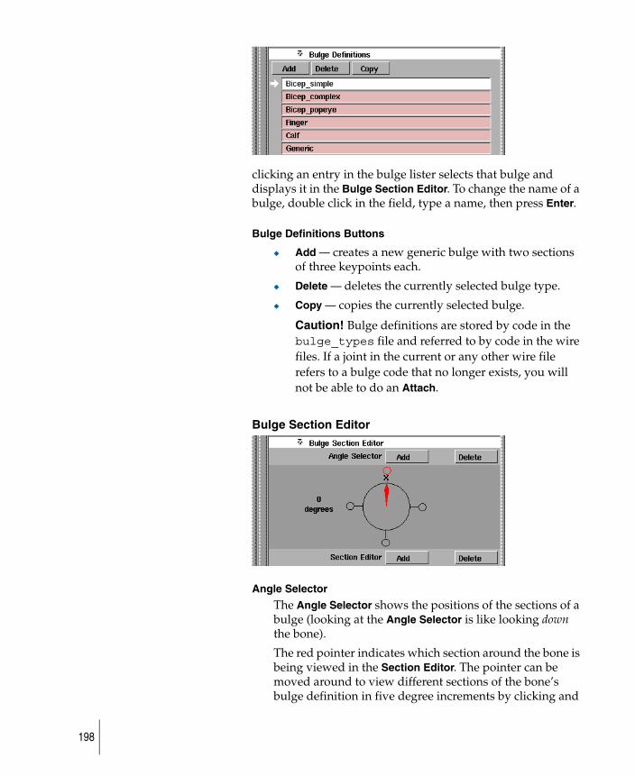
clicking an entry in the bulge lister selects that bulge and displays it in the Bulge Section Editor. To change the name of a bulge, double click in the field, type a name, then press Enter.
Bulge Definitions Buttons
◆ Add — creates a new generic bulge with two sections of three keypoints each.
◆ Delete — deletes the currently selected bulge type.
◆ Copy — copies the currently selected bulge.
Caution! Bulge definitions are stored by code in the bulge_types file and referred to by code in the wire files. If a joint in the current or any other wire file refers to a bulge code that no longer exists, you will not be able to do an Attach.
Bulge Section Editor
Angle Selector
The Angle Selector shows the positions of the sections of a bulge (looking at the Angle Selector is like looking down the bone).
The red pointer indicates which section around the bone is being viewed in the Section Editor. The pointer can be moved around to view different sections of the bone’s bulge definition in five degree increments by clicking and
198
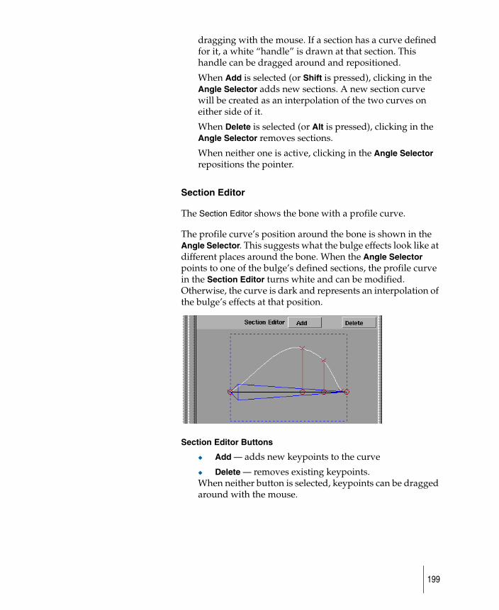
dragging with the mouse. If a section has a curve defined for it, a white “handle” is drawn at that section. This handle can be dragged around and repositioned.
When Add is selected (or Shift is pressed), clicking in the Angle Selector adds new sections. A new section curve will be created as an interpolation of the two curves on either side of it.
When Delete is selected (or Alt is pressed), clicking in the Angle Selector removes sections.
When neither one is active, clicking in the Angle Selector repositions the pointer.
Section Editor
The Section Editor shows the bone with a profile curve.
The profile curve’s position around the bone is shown in the Angle Selector. This suggests what the bulge effects look like at different places around the bone. When the Angle Selector points to one of the bulge’s defined sections, the profile curve in the Section Editor turns white and can be modified. Otherwise, the curve is dark and represents an interpolation of the bulge’s effects at that position.
Section Editor Buttons
◆ Add — adds new keypoints to the curve
◆ Delete — removes existing keypoints. When neither button is selected, keypoints can be dragged around with the mouse.
199
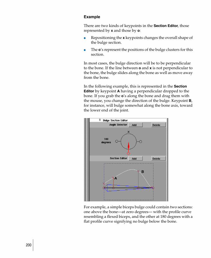
Example
There are two kinds of keypoints in the Section Editor, those represented by x and those by o:
● Repositioning the x keypoints changes the overall shape of the bulge section.
● The o’s represent the positions of the bulge clusters for this section.
In most cases, the bulge direction will be to be perpendicular to the bone. If the line between o and x is not perpendicular to the bone, the bulge slides along the bone as well as move away from the bone.
In the following example, this is represented in the Section Editor by keypoint A having a perpendicular dropped to the bone. If you grab the o’s along the bone and drag them with the mouse, you change the direction of the bulge. Keypoint B, for instance, will bulge somewhat along the bone axis, toward the lower end of the joint.
For example, a simple biceps bulge could contain two sections: one above the bone—at zero degrees— with the profile curve resembling a flexed biceps, and the other at 180 degrees with a flat profile curve signifying no bulge below the bone.
A
B
200
Restrictions
The following are restrictions on keypoints in the Section Editor.
● A profile curve must have at least two keypoints, one at the upper (left) end of the bone, and one at the lower (right) end.
● A keypoint’s position is bounded by the positions of the keypoints on either side of it.
Bending and bulging
The following basic steps show you how to create an arm with smooth bending at the elbow and bulging at the biceps.
1 Choose Animation > IK > Draw skeleton to create a joint hierarchy of three joints. The top joint will be the shoulder, the middle the elbow, and the lower the wrist.
2 Create arm geometry that surrounds the bones and the joints, and pick nothing to ensure that no geometry is active.
3 Choose Animation > Editors > Deformation control to display the Deformation Control window, then choose the CHARACTER BUILDER Frame Type. The default settings should be in effect at this time. To be sure, click the Edit > Reset button at the bottom of the window.
Follow these steps to specify bulging on the upper arm. Assume that you have already defined a bulge that has the effects you want and that you’ve called it “biceps.”
1 Since you only want to apply bulging to one joint, choose Hierarchy Depth NONE. (In this example, joint attributes are being set only for the shoulder joint.)
2 Click the Bulging toggle to turn bulging on.
3 Choose Pick > Object and then pick the entire skeleton. This selects the shoulder joint of the skeleton.
◆ Some attributes are very important, since they determine how a bulge will be applied to the skeleton. Zero Degree Section, Relate Transform, and Transform Range must all take into account the way your
201
skeleton was defined: its orientation in space, which rotation bends the elbow, and which values of that rotation should result in bulging.
4 Choose Set Attributes from the Frame Control menu. The system prompts: Modify joint attributes, then press GO
A Go icon is displayed at the bottom right of the current window.
Because you are in Set Attributes mode, any modifications you make in the Bulging Attributes or Joint Attributes sections of the window are stored on the selected joint hierarchy and will be reflected in the representation of the bulge effects displayed in the modeling windows.
5 Select your “biceps” bulge from either the Bulge Type menu or the Bulge Definitions lister.
6 Change the options in the Deformation Control window until you’re happy with the way the bulge looks in the modeling windows.
Notice that even though Bulging has been turned off in the window, bulging attributes on the shoulder joint have already been set. The state of the options in the window when Attach is selected shows what attributes are used on joints in the hierarchy that don’t have attributes explicitly stored on them already.
7 Click Go to exit the Set Attributes mode.
8 With the skeleton hierarchy still picked, pick the arm geometry as well.
9 Toggle Bulging off and set Hierarchy Depth to BELOW.
You are still getting smooth bending around the elbow, even though you didn’t set Upper and Lower Bound attributes on the elbow joint; those attributes are coming from the current values displayed in the window. (Naturally, the arm should have enough CVs around the elbow to permit smooth bending, and the displayed Bound values should sufficiently bracket those CVs.)
10 Choose Attach from the Frame Control menu.
202
When the Attach operation is completed, apply the desired rotation to the elbow joint and watch the upper arm bulge.
To see the effects of the bulge as you rotate the elbow joint (instead of when you release the mouse button), turn on Expression Updates: During Transform in the Preferences > Performance options window.
Additional notes
The CHARACTER BUILDER Attach operation automates two tedious tasks: creating all the bending and bulging clusters and generating the expressions linking bulging clusters to transformations on a DAG node. It is important to remember:
● Bending clusters are grouped under joint nodes in the SBD. There is one bending cluster created for each joint in the hierarchy selected during the Attach.
● Bulging clusters are created outside the joint hierarchy. Complex bulges can generate many bulge clusters, which are created compressed in the SBD—you can uncompress them as needed.
203

204

Apply a time warpHow to modify the times of the animation curves.
205
Apply a time warp
1 Create an animation on several objects.
2 Choose Animation > Create > New time warp, and a new time warp curve is created. This time warp curve is now applied to all channels of all active items.
The new time warp curve does not initially have any warping effects on the channels to which it is applied. You can open the Action Graph Editor in the Action window and edit the time warp curve to create different warping effects.
206
Cycle sections of animation with a time warp
To change the range of animation to be cycled
1 Create an animation on several objects and choose Animation > Create > New cycles warp.
A new time warp curve is created that will be applied to all specified channels of the selected animated items. These channels now cycle through the animation between frames 1 and 30 twice before continuing on with the remainder of the animation.
2 To change the range of animation to be cycled, or the number of cycles, choose New cycles warp ❑ to display the Cycle Options window and change the options.
An alternate way to cycle the complete range of animation on a channel for an infinite (or undetermined) number of times is to use the Cycles or Oscillate out-of-range type on the base action of a channel, instead of applying a timewarp. See the Action Tools menu items in the Action Window. For more information on timewarp curves, see
● Animation > Create > New time warp
● Animation > Create > New cycles warp
● Animation > Create > New scale warp
207
Scale animation timing with a time warp
To set new scale warps
1 Create an animation on several objects.
2 Choose Animation > Create > New scale warp ❒ to display the Time Scale Options window.
3 Set the Time Scale option to 2. A new timewarp curve is created that is applied to all specified channels of the selected animated items.
These channels are now all scaled by 2, which means that their animation now takes twice as long to play back.
● You can also scale the animation on channels by selecting the channels in the Action Window, and using Transform > Scale to scale the channels. See Animation > Editors > Action window for details.
208
Index
Aaction window 17, 30–32
command 30dollying 52expanding DAG nodes 85fast seg in 65, 73linear seg in 51moving camera 52repeating operations 85switching to pick tool 85timing curve 64, 72tracking 52using pickbox 85
actionsand channels 12base actions & time warps 12copying & pasting 17creating 9definition 13motion path 12parameter curve 12sharing between channels 17types of, in animation 12
add IK handlespline handles 97
addingcluster members 161selection handles 163
aim constraintsexample 145
alpha channeldisplaying in fcheck 38
animatable items 5animating
around a pivot 25basics of 4clusters 160DAG nodes 5definition 4flow 160objects 8parameters 11using expression channels 14using keyframes 28
verifying 11animation
action window 30automatic keyframing 45baking a sequence 140changing speed 51, 65, 73channels 30curve tangents 30curves 30cutting keyframes 56cycling with a time warp 205deleting 74editing 30editing motion path 64, 72fcheck 37flipbook 36keyframe prompt 28motion path type 47pasting 58playback options in fcheck 43playing back 36, 37time warp > new cycles
warp 205time warp > new scale
warp 206time warp > new time
warp 204timing curve 64, 72viewing frames 35viewing in UNIX 36viewing in Windows NT 37
animation effectsbanking turns 47deformation 47flow 47following a curve 47slug (mollusc) example 160
Animation menuIK > set rest pose 99
animation menuaction window 30create > new selection
handle 163fcheck 37flipbook 36IK > assume rest pose 102keyframe > copy 55
keyframe > cut 56keyframe > paste 58set key shape 165set motion 47, 60turntable 25view frame 35
animation parametersand channels 13definition 13expressions 14
animationsnon-unique solutions 118unique solutions 118viewing in fcheck 43viewing in flipbook 36
applyingnew time warps 204
arc lengthspline IK 133
assume rest pose 102options 103
auto keyframechanging values 46options 45
autofly toolcamera eye 15camera up vector 15camera view 15
axisof deformation 177
axis frame typedeformation percentage,
example 179
Bbaking
animation sequence 140definition 118, 129motion blur 140run IK 118
base actionsin animation channels 12
basic animation 4bending
example 199bones
actual size 94changing shape of 94creating simple spine
chain 121example of desk lamp 121turning off display 94using 94
bulge attributesdeformation control 194
bulge definitionsediting 86lister 196
bulge section editordeformation control 197editing bulge definitions 86
bulgescharacter builder 191definitions lister 196section editor example 198
bulgingand bending, example 199
bumpsin fcheck 39
buttonsin cluster editor 156in deformation control
window 175
Ccameras
camera eye 15camera up vector 15camera view 15
chainsrolling, definition 134twisting, definition 134
changingimages in fcheck 40
channels 30actions 9and animation parameters 13creating 8definition 13deleting 74description 8
expression channels 14many or one action 12one-to-many relationship 12using many actions 12verifying 11viewing particular actions 13
character builderattach 201bulges 191deformations 189frame control 190modify 191quick tips 86
childjoints 93
cluster editorand SBD window 159buttons 156changing percentages 157cluster percentages
options 157description 155edit menu 161list mode menu 161menus 161multi-cluster
transformations 159opening 155options 155other functionality 162percentage effect types 158pick menu 161scrolling 162
cluster membersadding 161copying 162moving 162removing 161transforming 162
clustersbulges 196collapsing 162compressing 156copying 154copying members 154creating 152expanding 156for deforming 173multiple 159notes and limitations 154picking 153splitting 162transforming, example 180
collapsingclusters 162
color channelsdisplaying separately in
fcheck 38in fcheck 43
compositingin fcheck 39
compressingclusters 156
constrain to 142aim 145orientation 144point 143
constrainingobjects 139objects to objects 142
constraintsanimation 140deleting 150example 140motion blur 140on invisible objects 141SDL files 137UV 147
copyingactions 17cluster members 154, 162clusters 154
create constraint 139creating
chain of bones desk lamp, example 121
channels for animation information 8
clusters 152clusters for deforming 173constraints on objects 139joints 93shapeshifter
interpolations 169shearing effects 187
curve deformationdeformation control 181examples 182
curve frame typedeformation options 181percentage effect 184
curvesanimation curves 30deformation 181
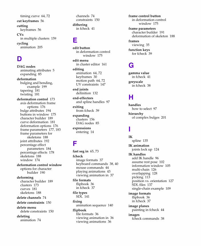
timing curve 64, 72cut keyframes 56cutting
keyframes 56CVs
in multiple clusters 159cycling
animation 205
DDAG nodes
animating attributes 5expanding 85
deformationbulging and bending,
example 199tapering 181twisting 181
deformation control 173axis deformation frame
options 176bulge attributes 194buttons in window 175character builder 189curve deformation 181deformation options 176frame parameters 177, 183frame parameters for
skeletons 188joint attributes 192percentage effect
parameters 184percentage effects 178skeletons 188window 174
deformation control windowoptions for character
builder 190deforming
character builder 189clusters 173curves 181skeletons 188
delete channels 74delete constraints 150delete menu
delete constraints 150deleting
animation 74
channels 74constraints 150
ditheringin fcheck 41
Eedit button
in deformation control window 175
edit menuin cluster editor 161
editinganimation 64, 72keyframes 30motion path 64, 72UV constraints 147
end jointsdefinition 132
end-effectorsand spline handles 97
exitingfrom fcheck 39
expandingclusters 156DAG nodes 85
expressionsentering 14
Ffast seg in 65, 73fcheck
image formats 37keyboard commands 38, 40mouse commands 44playing animations 43viewing animation in 37
file formatsflipbook 36in fcheck 37
file typesSDL 141
fixinganimation sequence 140
flipbookfile formats 36viewing animation in 36viewing animations 36
frame control buttonin deformation control
window 175frame parameters
character builder 191deformation of skeleton 188
framesviewing 35
function keysfor fcheck 39
Ggamma value
in fcheck 41greyscale
in fcheck 38
Hhandles
how to select 97hierarchy
of complex bulges 201
IIK
spline 135IK animation
joints lock up 124IK handles
add IK handle 96assume rest pose 102information window 105multi-chain 126overlapping 128picking 113position vs. orientation 127SDL files 137single-chain example 109
image formatsflipbook 36in fcheck 37
image planespainting in fcheck 44
imagesfcheck commands 38
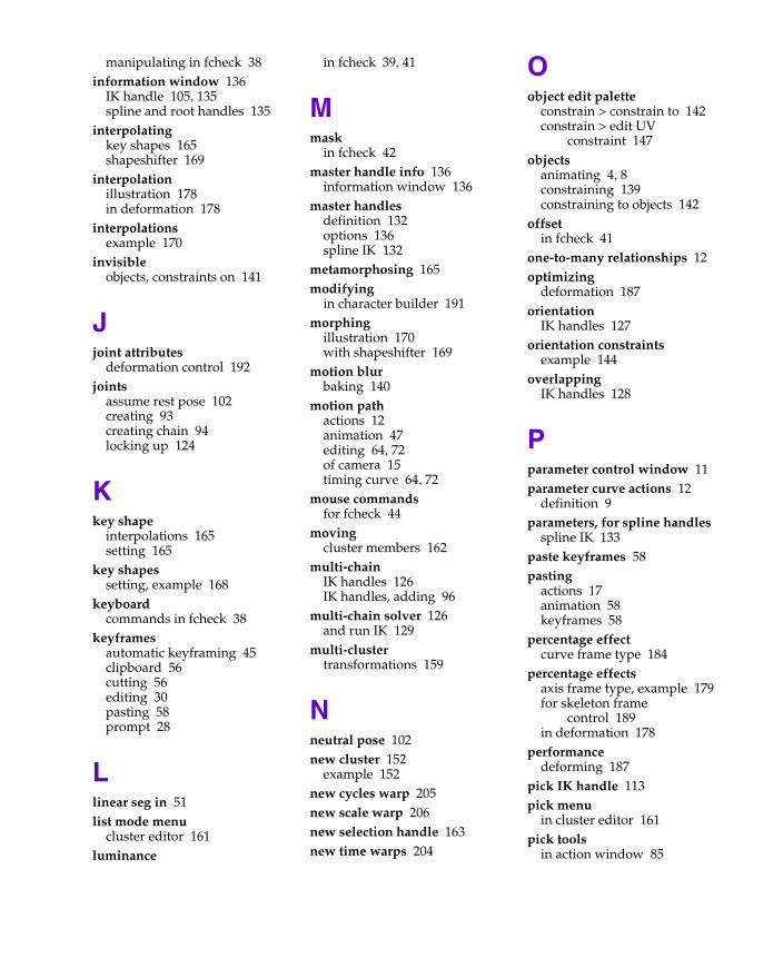
manipulating in fcheck 38information window 136
IK handle 105, 135spline and root handles 135
interpolatingkey shapes 165shapeshifter 169
interpolationillustration 178in deformation 178
interpolationsexample 170
invisibleobjects, constraints on 141
Jjoint attributes
deformation control 192joints
assume rest pose 102creating 93creating chain 94locking up 124
Kkey shape
interpolations 165setting 165
key shapessetting, example 168
keyboardcommands in fcheck 38
keyframesautomatic keyframing 45clipboard 56cutting 56editing 30pasting 58prompt 28
Llinear seg in 51list mode menu
cluster editor 161luminance
in fcheck 39, 41
Mmask
in fcheck 42master handle info 136
information window 136master handles
definition 132options 136spline IK 132
metamorphosing 165modifying
in character builder 191morphing
illustration 170with shapeshifter 169
motion blurbaking 140
motion pathactions 12animation 47editing 64, 72of camera 15timing curve 64, 72
mouse commandsfor fcheck 44
movingcluster members 162
multi-chainIK handles 126IK handles, adding 96
multi-chain solver 126and run IK 129
multi-clustertransformations 159
Nneutral pose 102new cluster 152
example 152new cycles warp 205new scale warp 206new selection handle 163new time warps 204
Oobject edit palette
constrain > constrain to 142constrain > edit UV
constraint 147objects
animating 4, 8constraining 139constraining to objects 142
offsetin fcheck 41
one-to-many relationships 12optimizing
deformation 187orientation
IK handles 127orientation constraints
example 144overlapping
IK handles 128
Pparameter control window 11parameter curve actions 12
definition 9parameters, for spline handles
spline IK 133paste keyframes 58pasting
actions 17animation 58keyframes 58
percentage effectcurve frame type 184
percentage effectsaxis frame type, example 179for skeleton frame
control 189in deformation 178
performancedeforming 187
pick IK handle 113pick menu
in cluster editor 161pick tools
in action window 85
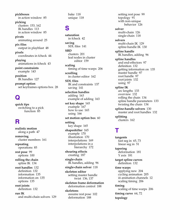
pickboxesin action window 85
pickingclusters 153, 162IK handles 113in action window 85
pivotsanimating around 25
pix filesoutput in playblast 48
pixelscoordinates in fcheck 44
playinganimations in fcheck 43
point constraintsexample 143
positionIK handles 127
prompt optionset keyframes options box 28
Qquick tips
switching to a pick function 85
Rrealistic motion
along a path 47removing
cluster members 161repeating
operations 85rest pose 99
options 100rolling the chain
spline IK 134root handles 132
definition 132information 135information on 135options 135
root jointsdefinition 132
run IKand multi-chain solvers 129
bake 118unique 118
Ssaturation
in fcheck 42saving
SDL files 141SBD
clusters 201leaf nodes in cluster
editor 159scaling
timing of time warps 206scrolling
in cluster editor 162SDL files
IK and constraints 137saving 141
selection handlesadding 163example of adding 163
set key shape 165example 167how to use 165using 166
set motion option box 60setting
key shape 165shapeshifter 165
example 170illustration 170interpolations 169interpolations in a
hierarchy 172shearing effects
creating 187single-chain
IK handles, adding 96single-chain solver 118skeleton editor
setting master handle twist 136, 137
skeleton frame deformationdeformation control 188
skeletonsassume rest pose 102deformation 188
setting rest pose 99topology 91with non-unique
behavior 126solver
multi-chain 126single-chain 118
solversmulti-chain IK 129spline-handle IK 130
spline handleIK handles, adding 96
spline handlesand end-effectors 97definition 132getting information on 135master handle 97root handle 97root joints 132using 97
spline IKarc lengths 133overview 132rolling the chain 134spline handle parameters 133twisting the chain 134
spline-handle solvers 130master and root handles 132
splittingclusters 162
Ttangents
fast seg in 65, 73linear seg in 51
taperingdeformation 181Y axis 181
target spline curvesdefinition 132
time warpsapplying new 204cycling animation 205in animation channels 12scaling timing 206
timingscaling of time warps 206
timing curve 64, 72topology
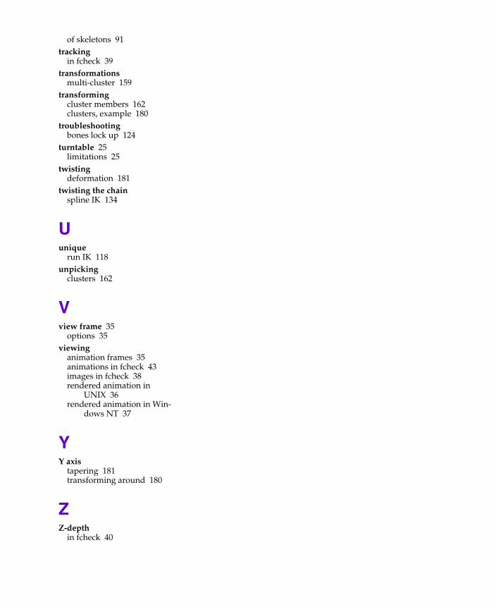
of skeletons 91tracking
in fcheck 39transformations
multi-cluster 159transforming
cluster members 162clusters, example 180
troubleshootingbones lock up 124
turntable 25limitations 25
twistingdeformation 181
twisting the chainspline IK 134
Uunique
run IK 118unpicking
clusters 162
Vview frame 35
options 35viewing
animation frames 35animations in fcheck 43images in fcheck 38rendered animation in
UNIX 36rendered animation in Win-
dows NT 37
YY axis
tapering 181transforming around 180
ZZ-depth
in fcheck 40