Embed Size (px)
Citation preview
Anionic Polyacrylamide Hydraulic Dredging with On-site DisposalCASE STUDY
Sustainable Technologies Evaluation Programwww.sustainabletechnologies.ca
An Initiative of:
Stor
mw
ater
Mai
nten
ance
Ser
ies
The use of polymer technology during both mechanical and hydraulic dredging operations is gaining popularity as non-con-ventional methods are explored by the stormwater manage-ment community. Hydraulic dredging offers a viable alternative to stormwater management facility clean out when site and project specific constraints make mechanical dredging difficult or impossible. Polymer flocculants are often used in conjunction with hydraulic dredging as a means of separating sediment from water in a slurry. The current case study describes the use of polymer-as-sisted hydraulic dredging to remove sediment from a stormwater management pond in the City of Vaughan. The sediment, which was captured in sediment dewatering bags used to dewater the slurry, was buried in the onsite sediment drying area, within the bags.
INTRODUCTION
Municipality City of VaughanCleanout Party Aquatech DewateringDrainage Area Land Use ResidentialPond Age at Time of Cleanout 5 yearsDrainage Area (ha) 42.95Permanent Pool Depth (m) 1.40Permanent Pool Volume (m3/ha) 70Water Quality and Erosion Control Volume (m3/ha) 95Sediment Removal Method Hydraulic DredgingSediment Handling Method Buried on Site
POND PROFILE

Case StudyPolymer-Assisted Hydraulic Dredging with On-site Disposal
March 2016Sustainable Technologies Evaluation Programwww.sustainabletechnologies.ca 2
PROJECT OBJECTIVES
SITE DESCRIPTION
Figure 1. Location of Pond 91 in Vaughan, ON.
METHODS
One of the primary conditions imposed by municipalities before they will assume a stormwater management pond is that the facility is restored to its original design capacity. The stormwater pond described in this case study was owned by the developer, Metrus Development, and had not been assumed by the City of Vaughan at the time of dredging in 2014. Based on a bathymetric survey completed in 2013, it was determined that 750 m3 of sediment had accumulated in the pond since it was constructed.
The primary objective of the project was to remove this accumulated sediment so that the pond would be restored to a condition in which it could be assumed by the City of Vaughan. Metrus Development retained the services of Aquatech Dewatering to complete this work. Other project objectives included:
• Prevent the release of sediment to the receiving stream;
• Minimize the ecological disturbance of dredging activities to wildlife that inhabit the pond area;
• Repair water control structures where needed;
• Re-plant pond banks and any restore any other areas where vegetation removal was required for maintenance access and sediment on-site disposal;
• Complete dredging and associated activities on schedule and within budget.
The new Vellore Village development has three stormwater ponds to treat stormwater runoff, all scheduled to be cleaned out at different times prior to assumption by the City of Vaughan. Pond 91, highlighted in this case study, is located west of Pine Valley Drive between Major Mackenzie Drive and Rutherford Road in Vaughan, Ontario (Figure 1). It receives stormwater runoff from a 46.2 ha drainage area in which the land use is primarily residential. The pond effluent is discharged to a Marigold Creek tributary, which makes its way to the East Humber River through the adjacent Kortright Centre for Conservation. The Vellore Village development construction was initiated in 2005, while the pond was built in 2009.
assessing a new series of equipment for hydraulic dredging. While there was some risk associated with the use of this new equipment, the parties involved reached an agreement on price and contingency that allowed the project to move forward.
Pond Survey
An as-built survey was conducted in 2010 to establish a baseline bathymetry of the pond. Once the pond cleanout planning was un-derway, a bathymetric survey was conducted in 2013 utilizing sonar technology. It was determined that the sonar survey overestimated the volume of sediment that had accumulated in the pond, and thus the pond was re-surveyed using the disk and rod method (Figure 2). In this method, a flat disk is attached to a long metal rod, which is submerged in the water until the bottom of the disk is positioned relatively flat on the pond bottom. A GPS total station survey was utilized to obtain high resolution vertical and horizontal measure-ments of the disk through a reflector attached at the top of the disk. Based on the survey, it was determined that the total volume of sediment accumulated in the pond was 750 m3, which is equivalent to 48% of the permanent pool volume.
Sediment Characterization
Four composite sediment samples were collected from the north-east, southeast, southwest and northwest quadrants of Pond 91
Following a site assessment and considering the side slopes of the pond, it was determined that mechanical dredging was not a feasible option for this pond. The contracted company (Aquatech Dewatering) was also interested in using this pond as a pilot for
Sustainable Technologies Evaluation Programwww.sustainabletechnologies.ca
An Initiative of:
using hand sampling methods. Samples were submitted to Maxxam Analytics for analysis of general inorganic parameters and select metals. Results were compared to both Tables 1 and 2 of the Soil, Ground Water and Sediment Standards for Use Under Part XV.1 of the Environmental Protection Act. For all the parameters for which
Case StudyPolymer-Assisted Hydraulic Dredging with On-site Disposal
the sediment was tested, it was found to meet the thresholds in Table 2 as well as the more stringent criteria in Table 1. Based on these results, it was determined that the chemistry of the material would make it suitable for reuse on any land based sites. As such, it was considered appropriate to bury the material onsite as planned from the outset of the project.
Site Preparation
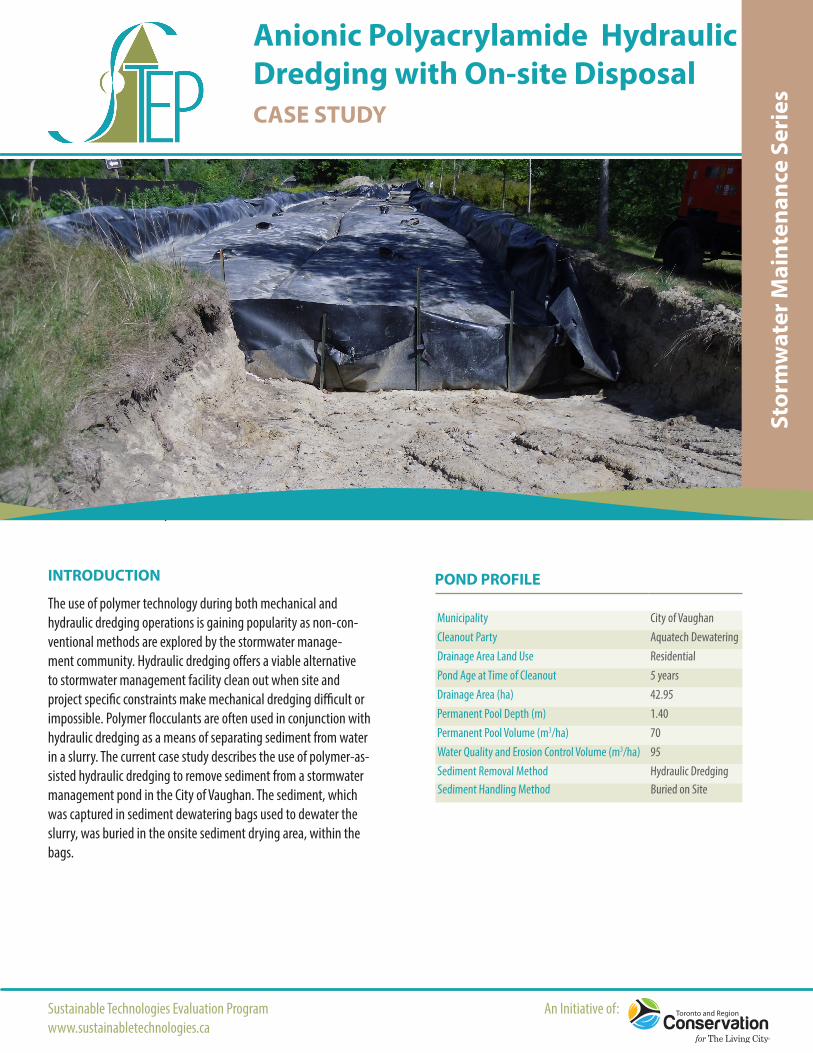
Site preparation was dictated by the sediment disposal and dredging methods selected for this project (Figure 3). The cleanout was initiated in the spring when water levels are relatively high, which is helpful as it allows the hydraulic dredge easier access to all areas, particularly those near the shoreline. The AquaBarrier shown in Figure 3 was initially going to be used to get water levels to be high enough to operate the dredge in one half of the pond at a time. This ultimately was not necessary because water levels were naturally high enough to operate the dredge effectively. This is an import-ant factor that distinguishes hydraulic dredging from mechanical dredging, which is typically carried out during hot, dry weather when water levels are at their lowest. As no heavy machinery is required for hydraulic dredging, there was no significant vegetation
Figure 3. Schematic aerial view Pond 91 of site preparation.
3
Figure 2. Field crew conducting a bathymetric survey of Pond 91 using a standard disk, rod and total station method.
Case StudyPolymer-Assisted Hydraulic Dredging with On-site Disposal
March 2016Sustainable Technologies Evaluation Programwww.sustainabletechnologies.ca
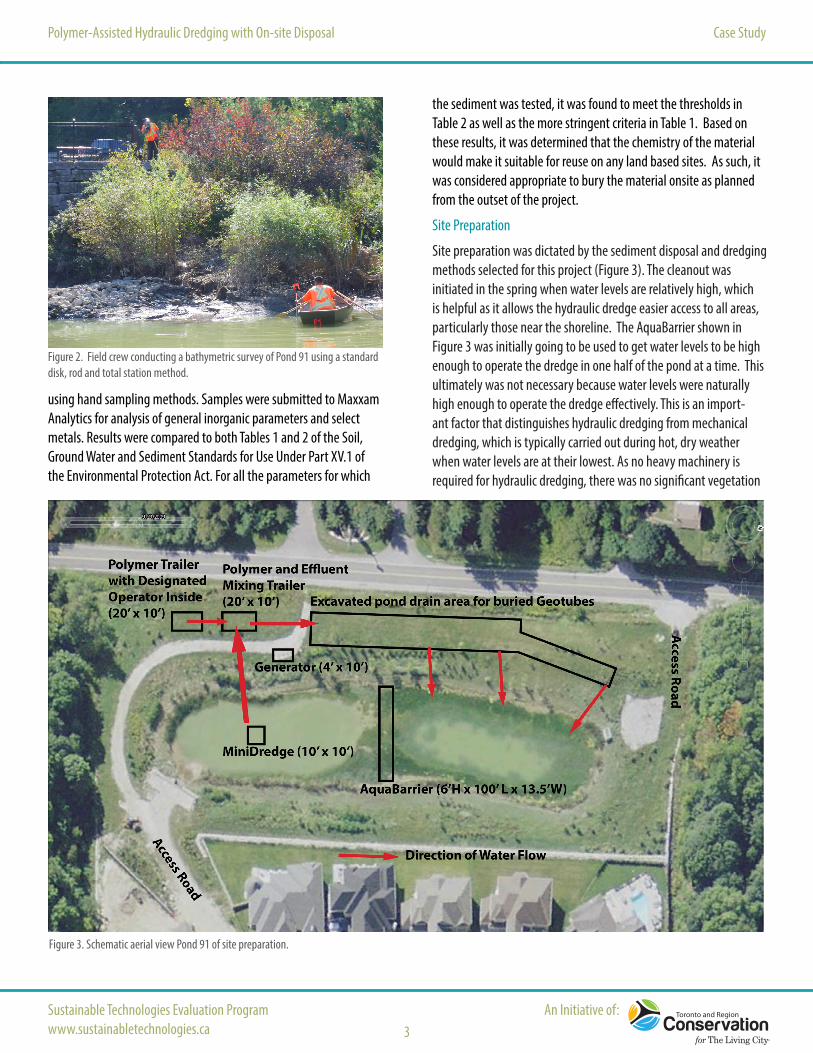
removal and the necessary erosion and sediment control measures were minimal. However, cattail removal was necessary to maximize the dredge’s accessibility to the shores (Figure 4). The site has two access roads, which were both utilized during the site mobilization and set-up. The primary activities associated with preparing the site for sediment removal were:
• Excavation of a large area for sediment dewatering in Geotubes, and also for permanent burial;
• Launching the hydraulic dredge and preparation of a steel cable system to facilitate its movement;
• Installation of pumps, pipes and hoses conveying pond water and polymer between the dredge, polymer supply trailer, poly-mer and effluent mixing trailer and sediment dewatering bags.
Within the existing sediment drying area, an excavator was used to create a dewatering and burial area that was 30 ft wide, 300 ft long and 3 ft deep. The area was sized to house five large dewatering bags but ultimately only four were needed to capture the dredged sediment. Excavated material was hauled to a construction site to use as fill material. The excavation was sized to house five sediment dewatering bags, but only four were necessary to accommodate the extracted volume of sediment. A layer of geosynthetic cloth was placed along the bottom of the excavation followed by a layer of gravel. The dewatering bags were laid out on top. The gravel stone maintained a porous volume though which water from the dewater-ing bags was able to drain. The water re-entered the pond through three fluming ditches (containing 12” DR17 HDPE pipes) in each bag.
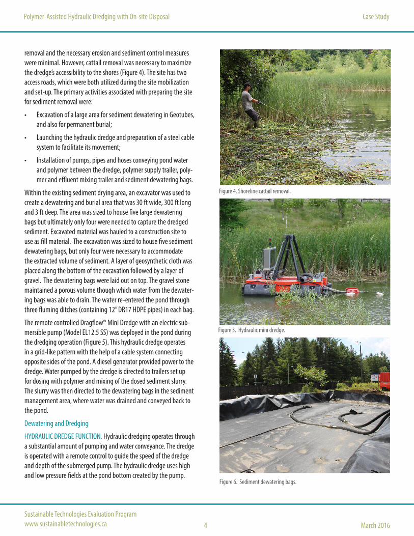
The remote controlled Dragflow® Mini Dredge with an electric sub-mersible pump (Model EL12.5 SS) was deployed in the pond during the dredging operation (Figure 5). This hydraulic dredge operates in a grid-like pattern with the help of a cable system connecting opposite sides of the pond. A diesel generator provided power to the dredge. Water pumped by the dredge is directed to trailers set up for dosing with polymer and mixing of the dosed sediment slurry. The slurry was then directed to the dewatering bags in the sediment management area, where water was drained and conveyed back to the pond.
Dewatering and Dredging
HYDRAULIC DREDGE FUNCTION. Hydraulic dredging operates through a substantial amount of pumping and water conveyance. The dredge is operated with a remote control to guide the speed of the dredge and depth of the submerged pump. The hydraulic dredge uses high and low pressure fields at the pond bottom created by the pump.
4
Figure 5. Hydraulic mini dredge.
Figure 6. Sediment dewatering bags.
Figure 4. Shoreline cattail removal.

The pump creates a high pressure at the top of the sediment, which results in a low pressure at the suction point of the pump. As such, the slurry moves from the high pressure to the low pressure and into the pump, which creates a circulation. The pump functions at a rate of 80 m3/hour.
The movement of the dredge was guided by steel cables attached at either end of the pond, while a remote control was used to move the dredge forward and backward, control its speed and determine the depth of the submersible electric pump. The colour of the slurry be-ing pumped into the dosing and mixing trailer was monitored in real time as a means of determining when the pump should be moved. If the slurry appeared to be relatively clear with low solids content, the pump would be lowered in order to capture the dark sediment at the pond bottom. A lighter coloured slurry with high solids content was indicative that the pump had reached the clay pond liner and thus the pump could be advanced forward to clean the next section.
POLYMER FORMULATION AND DOSING RATE. As a flocculant, anionic PAM functions by causing sediment particles to bind to one another to create larger agglomerated masses. These heavier agglomerated particles are more prone to gravitational settling and easier to filter using a dewatering bag. For the polymer dosing and mixing aspect of the clean out, Aquatech Dewatering retained the services of of Bishop Water Technologies. Bishop Water procured the polymer product and provided the infrastructure necessary to dose and mix the slurry. The polymer product was injected in-line into the slurry as it was pumped out of the pond and into the dosing trailer. The solution injected was a mixture of granular anionic PAM and water, and was selected base on its proven effectiveness and low toxicity (Rocha and Van Seters, 2013). Prior to commencement of the dredging, bench tests were carried out to determine the appropri-ate polymer and required amount per unit volume of slurry. The dosing rate was determined through an algorithm developed on site following in-situ testing of the actual suspended solids in the slurry. The algorithm, dependent on measured solids concentrations, was applied to the polymer release tank to control the volume of polymer injections in real time.
DEWATERING. The chemical reaction between the injected polymer and suctioned slurry begins its reaction while in the polymer and effluent mixing tanks while being conveyed through hoses into the sediment dewatering bags for further consolidation and dewatering (Figure 6). The PAM dosed slurry was pumped though a mixing zone that created turbulent flow conditions allowing for the polymer to react more fully with the sediment. After this mixing occured, the slurry was pumped into the dewatering bags, which filtered out
Case StudyPolymer-Assisted Hydraulic Dredging with On-site Disposal
Sustainable Technologies Evaluation Programwww.sustainabletechnologies.ca
An Initiative of:5
Figure 7. Clear water exiting the sediment dewatering bags.
Figure 9. Sediment dewatering bags at the end of dredging.
Figure 8.Level of sediment consolidation from within the dewatering bags.

RESULTS
Polymer-Assisted Hydraulic Dredging with On-site Disposal Case Study
March 2016Sustainable Technologies Evaluation Programwww.sustainabletechnologies.ca 6
any particles larger than 425 μm. In addition to filtration, the bags also provide an opportunity for gravitational settling of suspended sediment particles. There were two entry points in each dewatering bag so that as one side became filled with sediment, the hose could be removed and re-attached at the adjacent entry point. The water that drained from the bags was conveyed from the dewatering area and back into the pond via three 4-inch pipes (Figure 7). The flow path from the pipe to the pond was stabilized with geotextile fabric to prevent erosion.
The four sediment bags were consecutively filled with polymer-lad-en effluent and therefore the dewatering process was ongoing throughout the duration of dredging and beyond. Since the sedi-ment was to be left on site within the dewatering bag containment area, the duration of sediment drying did not pose a constraint on the project timeline. The expected time for sediment consolidation was one month; however, the back-filling of the containment area took place roughly two months following the end of the dredging operations as per the contractor’s availability.
Sediment Disposal
The sediment contained in the dewatering bags was left within the excavated containment area, avoiding the need to haul and dispose of sediment off site (Figure 8-9). The top of the bags was cut open to allow the dredged consolidated sediment to integrate with the soil used to backfill the sediment containment area. The area was back-filled, leveled and hydroseeded. On sites where sediment contains higher contaminant levels than on this site, it is possible that this method of onsite reuse and integration with existing site soils could result in reduced contaminant levels over time. The churning of the soil by microbes could potentially help to mix the dredged sediment with the backfilled soil, and also help reduce contaminant levels through biological breakdown and uptake. While this has not been proven through a field study specifically looking at dredged storm-water facility sediment, the soil remediation power of microbes is a widely accepted phenomenon.
Site Restoration
The pond facility was designed with a sediment management area and two access roads, which nearly eliminated the need to remove or damage existing vegetation. Therefore, site restoration mainly in-volved the backfilling of the sediment dewatering bags containment area. Fill from a different construction site was used for this purpose.
The duration of the dredging of Pond 91 took longer than antici-pated for various reasons (see below). Nevertheless, the sediment removal undertaking was successful in restoring the pond volume back to its design objective, enabling the transfer of ownership between the developer and City of Vaughan.
Removal of 1000 m3 from Pond 91
The total volume of sediment to be removed was 750 m3, however by the end of the operation 1000 m3 of sediment had been removed. The larger volume of removed sediment is attributed to the real time monitoring of the effluent colour and density. This strategy allowed technicians to ensure that all sediment was removed from an area before advancing the dredge to the next area. The fact that signifi-cantly more sediment was removed than initially surveyed indicates that an error was present either in the as-built bathymetric survey or the sediment accumulation survey. A total of 5000 m3 of water was pumped from the pond, which resulted in 1000 m3 of removed sediment, at 20% sediment removal density.
Need for minimal site alteration and restoration
The odours and dust generation often associated with mechanical dredging are not present during hydraulic dredging operations, and were therefore not an issue for the current project. Heavy machinery was not utilized and noise was significantly reduced.
Improved pond functioning
The removal of 1000 m3 restored the pond to its original design and facilitated the successful transfer of ownership from the developer to the City of Vaughan. The sediment removed was largely associated with erosion of soils from the construction site, which are generally much cleaner than sediment transported in runoff from paved surfaces. Therefore, land disposal of sediment was considered to be an acceptable approach in this instance.
Excessive cattail growth hindered the commencement of the dredg-ing
Although cattails serve biological, erosion prevention and hydraulic functions within the facility, their excessive growth in the pond fringe areas hindered access to the open water area. Because hydraulic dredges operate from the surface of open water, while cattails reduce the area of open water, they need to be removed in order to allow the dredge to access the fringe areas of the pond.

Aquatech Dewatering: Polymer-Assisted Hydraulic Dredging with On-site Disposal Case Study
7
CHALLENGES AND LESSONS LEARNED
The clean out of Pond 91 applied hydraulic dredging due to site con-straints and also as an opportunity to pilot a new hydraulic dredging process for the contractor, Aquatech Dewatering. Although the proj-ect plan was laid out in detail and the hydraulic dredge functioned as expected, there were site specific challenges that hampered the contractor’s ability to complete the work cost effectively and
This case study has been prepared by the Toronto and Region Conservation Authority’s Sustainable Technologies Evaluation Program, with funding support from the City of Toronto, York Region, Region of Peel, and the Great Lakes Sustainability Fund. Aquatech Dewatering and Bishop Water Technologies carried out the pond clean out project described herein, and as such provided the information and site access required for the development of this document. For more information about this project, please contact [email protected].
For information on STEP’s other stormwater management initiatives, or to access the new guidance on stormwater pond cleanouts, visit us online at www.sustainabletechnologies.ca
March 2016Sustainable Technologies Evaluation Programwww.sustainabletechnologies.ca
within the projected timeline. Obtaining a bathymetric survey using a new technology, such as sonar, proved to be problematic when comparing results to those obtained from standard methods. This is especially important for hydraulic dredging when the depth of the pump is pre-determined based on the bathymetry of the pond. Although the technical team was able to resolve this issue, it slowed the process during the initial project stages. The second major issue was the presence of large articles in the pond bottom, which can be mitigated by ensuring that trash racks and safety grates remain locked, and by educating local residents on the function of the facility.
Overall, the cleanout operation was concluded successfully with the pond restored to its original design capacity. The project is interesting as it serves as a demonstration several unconventional methods, including polymer-assisted hydraulic dredging and onsite sediment burial. It should be noted that on-site disposal of sediment is not typically feasible during the clean out of older ponds, which are usually under municipal ownership. These ponds that drain built out catchments tend to contain sediment that is more contaminated, which will often limit the reuse options for that material. Further, many older ponds that exist today have not been built to include a sediment management area, and there is usually limited space for sediment storage adjacent to the pond.
REFERENCESRocha L, Van Seters T (2013) Polymer Backgrounder: The Nature, Efficacy and Safety of Polymers for Erosion and Sediment Control. Toronto and Region Conservation Authority’s SustainableTechnologies Evaluation Program, Toronto, Ontario.
Garbage from the bottom of the pond clogged the electric submers-ible pump
Garbage that has washed off into the pond during storm events or deliberately deposited there by local residents posed a problem during the suction process, as the equipment is designed to suction fine sediment only. A cutter is attached to the submersible pump to cut through some bottom thriving vegetation and cattail, but this cutter is not powerful enough to mince large pieces of garbage (e.g. sweaters and shoes) into pieces small enough that they could be suctioned. Throughout the first stages of dredging, articles would frequently get stuck in the cutter, which resulted in an electrical shutdown of the dredge. After multiple attempts were made to overcome this issue, technicians decided to remove the cutter and halt dredging only when garbage clogged the pump. This procedure reduced the frequency of electrical shutdowns of the pump.