Embed Size (px)
Citation preview
CONTROL OF RELIABLE CHARGING INFRASTRUCTURE FOR EVS
WITH RENEWABLE ENERGY GRID INTERFACE
ANJEET KUMAR VERMA
DEPARTMENT OF ELECTRICAL ENGINEERING
INDIAN INSTITUTE OF TECHNOLOGY DELHI
MAY 2021

© Indian Institute of Technology Delhi (IITD), New Delhi, 2021
CONTROL OF RELIABLE CHARGING INFRASTRUCTURE FOR EVS
WITH RENEWABLE ENERGY GRID INTERFACE
by
ANJEET KUMAR VERMA
DEPARTMENT OF ELECTRICAL ENGINEERING
Submitted
in fulfilment of the requirements of the degree of Doctor of Philosophy
to the
INDIAN INSTITUTE OF TECHNOLOGY DELHI
MAY 2021

CERTIFICATE
This is to certify that the thesis entitled, “Control of Reliable Charging Infrastructure for EVs
with Renewable Energy Grid Interface” being submitted by Mr. Anjeet Kumar Verma for the
award of the degree of Doctor of Philosophy is a record of bonafide research work carried out by
him in the Department of Electrical Engineering of Indian Institute of Technology Delhi.
Mr. Anjeet Kumar Verma has worked under my guidance and supervision and has fulfilled
the requirements for the submission of this thesis, which to my knowledge has reached the req-
uisite standard. The results obtained here in have not been submitted to any other University or
Institute for the award of any degree.
Date: 10-05-2021
Place: New Delhi
(Prof. Bhim Singh)Department of Electrical Engineering
Indian Institute of Technology DelhiHauz Khas, New Delhi-110016, India
i
ACKNOWLEDGEMENTS
I wish to express my deepest gratitude and indebtedness to Prof. Bhim Singh for providing me
guidance and constant supervision to carry out the Ph.D. work. Working under him has been a
wonderful experience, which has provided a deep insight to the world of research. Determination,
dedication, innovativeness, resourcefulness and discipline of Prof. Bhim Singh have been the in-
spiration for me to complete this work. His consistent encouragement, continuous monitoring and
commitments to excellence have always motivated me to improve my work and use the best of
my capabilities. Due to his blessing I have earned various experiences, other than research, which
will help me throughout my life. My sincere thanks and deep gratitude are to Prof. Sukumar
Mishra, Dr. Anandrup Das, Dr. Ashu Verma, all SRC members for their valuable guidance and
consistent support during my research work. I wish to convey my sincere thanks to Prof. Bhim
Singh, Prof. G. Bhuvaneswari, Prof. B. K. Panigrahi, Prof. Mummadi Veerachary, Prof. (late) KR
Rajagopal, Dr. Anandarup Das and Dr. Ramkrishan Maheshwari for their valuable inputs during
my course work, which has made the foundation for my research work. I am grateful to IIT Delhi
for providing me the research facilities. I would wish to express my sincere gratitude to Prof.
Bhim Singh, Prof. G. Bhuvaneswari and the Prof. A.K. Jain, as Prof. in-charge of PG Machine
Lab, for providing me immense facilities to carry out experimental work. Thanks are due to Sh.
Srichand, Sh. Puran Singh, Sh. Jagbir Singh, Sh. Amit Kumar, Sh. Jitendra, Sh. Anurag Singh,
Sh. Rahul Divakar of PG Machines Lab, UG Machines Lab and Power Electronics Lab., IIT Delhi
for providing me the facilities and assistance during this work. I would like to thank all my se-
niors, Dr. Chinmay Jain, Dr. Rajan Sonkar, Dr. Ikhlaq Hussain, Dr. Aniket Anand, Dr. Nishant
Kumar, Mr. Anshul Varshney, Dr. Saurabh Shukla, Dr. Radha Kushwaha, Dr. Nidhi Mishra, Dr.
iii

Geeta Pathak, Dr. Shailendra Kumar Dwivedi, Dr. Shadab Murshid, Dr. Piyush Kant, Dr. Sachin
Devassy, Mr. Vineet P. Chandran, Dr. Tripurari Nath Gupta, Ms. Shatakshi, Ms. Vandana Jain
and Dr. Anjanee Kumar Mishra to motivate me in the starting of my research work. I would like
to use this opportunity to thank Dr. Seema, Mr. Sreejith R., Mr. Debashish Mishra, Mr. Gurmeet
Singh, Mr. Yalavarthi Amarnath, Mr. Suri Praneeth, and Mr. Priyvrat Vats who have constantly
helped me on all technical issues. I would like to thank Dr. Deepu Vijay Menon, Ms. Subarni
Pradhan, Dr. Tabish Nazir Mir, Mr. Praveen Kumar Singh, Dr. Amresh Singh, and all other col-
league for their valuable aid and cooperation. My heartfelt thanks to Mr. Sunil Kumar Pandey,
Mr. Utkarsh Sharma, Mr. P. Sambasivaiah, Mr. Munesh Kumar Singh, Ms. Rohini Sharma, Ms.
Pavitra Shukl, Ms. Farheen Chishti, Mrs. Shubhra, Mr. Aryadip Sen, Mr. Mohd. Kashi, Ms.
Hina Parveen, Ms. Rashmi Rai, Mr. Niranjan Rao Deevela, Ms. Yashi Singh, Mr. Souvik Das,
Mr. Sudip Bhattacharya, Ms. Shalvi Tyagi, Mr. Sandeep Kumar Sahoo, Mr. Gaurav Modi, Mr.
Syed Bilal Qaiser Naqvi, Mr. Jitendra Gupta, Mr. Utsav Sharma, Mr. Sayandev Ghosh, Mr.Saran
Chaurasiya, Mr. Vivek Narayanan, Mr. Rahul Kumar, Mr. Sharankumar Shastri, Mr. Deepak
Saw, Mr.Shivam Kumar Yadav, Ms. Kousalya V, Ms. Sanjenbam Chandrakala Devi, Mr. Saurabh
Mishra, Mr. Muhammad Zarkab Farqooi, Ms.Kripa Tiwari, Mr. Rohit Kumar, Mr.Vipin Kumar
Singh, Mr. Arjun Kumar, Mr. Biswajit Saha, Ms. Farha Siddique, Mr. Sumit Kumar, Mr. Gaurav
Kumar, Mr. Madan Gopal Sharma, and all other PG Machine Lab mates for their help and informal
support in pursuing this research work.
I would like to thank my friends, Mr. Pragyey Kumar Kaushik, Mr. Ajay Singh, Mr. Adarsh Singh,
Mr. Pankaj Yadav, Mr. Parmeshwar Saini, Dr. Deepak Gupta, Mr. Ravish Kumar, Dr. Avneet Ku-
mar Chauhan, Dr. Naresh K Pilli, Dr. Motiur Reza, Dr. M. Raghuram, Dr. V. Venkat Ratnam,
Mr. Anand, Mr Ankit Kumar, Mr. Deepak Patil, Mr. Mohinish Singh, Dr. Sarvesh Mishra, Mr.
iv

Athar Kamal, Mr. Nitin Gupta, Mr. Jaswant, Mr. Satyaranjan, Mr. Ajay Kumar Agrawal for their
unconditional support and motivation.
I would also like to thank Mr. Yatindra, Mr. Satish, Mr. Narendra, Mr. Sandeep and all other Elec-
trical Engineering Department office staff for being supportive throughout. I am likewise thankful
to those who have directly or indirectly helped me to finish my dissertation study.
Moreover, I would like to thank Department of Science and Technology (DST), Govt. of India
for funding this research work under the fund for improvement of S&T infrastructure in higher
educational institutions (FIST), UKICERI (RP03391), UI-ASSIST (RP03443), SERI-II and J C
Bose Fellowship (RP03128).
My deepest love, appreciation and indebtedness go to my father, Mr. Chandrabali Verma for his
dreams, sacrifices and wholeheartedly endorses. His trust in my capabilities have always moti-
vated me to reach higher academic degrees. I would like to convey my unbounded love to my
mother Mrs. Chandrawati Verma as I spent a major part of my childhood in her lap. A great deal
of effort, endurance, encouragement and blessings of my parents. Moreover, I would like to thank
my brothers Mr. Sanjeet Kumar Verma and Mr. Ankit Kumar Verma, my sister Mrs. Renu Singh
Verma, and other family members for giving me the inner strength and wholeheartedly support.
Their trust in my capabilities had been a key factor to all my achievements. At last, I am beholden
to almighty for their blessings to help me to raise my academic level to this stage. I pray for their
benediction in my future endeavors. Their blessings may be showered on me for strength, wisdom
and determination to achieve in future.
Date: 10-05-2021
Anjeet Kumar Verma
v
ABSTRACT
In view of the proliferation of EVs, the development of the multi-functional EV charging infras-
tructure is of paramount importance. In addition, integrating renewable energy into the core of
the EV charging system is crucially significant. Therefore, this thesis deals with the design, con-
trol and implementation of various configurations of PV array, wind energy conversion system
(WECS), storage battery, grid/DG set based EV charging station, beneficial for EVs, domestic
loads, and utility. For EVs and the household loads, the charging stations are designed to operate
in multimodes such in an islanded mode, the grid connected mode and the DG set connected mode
with automatic and seamless mode transition among them, to provide the uninterruptible power.
Moreover, it takes care of the harmonics distortion created by the EVs and the household loads by
mitigating them locally, thus avoiding the penalty from the utility. For utility, the charging station
provides the facility to exchange active and reactive powers with the grid in vehicle-to grid (V2G),
grid-to-vehicle (G2V), storage-to-grid (S2G), grid-to-storage (G2S) etc., without compromising
the power quality at grid side. Besides, the charging station supports other multi-functional oper-
ations such as vehicle-to-home (V2H), storage-to-home (S2H), storage-to-vehicle (S2V), vehicle-
to-storage (V2S) and vehicle-to-vehicle (V2V), which improves the operational efficiency of the
charging station. In the designed charging station configurations, a single voltage source converter
is used to performs various tasks, such as energy management among different energy sources, ex-
traction of maximum power from the PV array, the regulation of voltage and frequency of the DG
set etc. The charging station also ensures the maximum power point operation of the renewable
energy sources for maximum utilization of them. All the designed charging station configurations
are modelled and simulated in the MATLAB/Sumulink environment using the Simpower technol-
vii

ogy blocks and the same has been verified through the laboratory prototype. The performance of
the charging stations are discussed in various steady state conditions and the dynamic conditions.
viii

ABSTRACT
ईवी क परसार को दखत हए, मलटी फकशनल ईवी चारजिग इफरासटरकचर का रवकास सबस महतवपरण ह। इसक अलावा, ईवी चाजण
परराली क मल म अकषय ऊजाण का एकीकरर करना महतवपरण ह। इसरलए, इस शोध-परबनध म पीवी सररी, पवन ऊजाण रपातरर
परराली, सटोरज बटरी, रिड / डीजी सट आधाररत ईवी चारजिग सटशन क रडजाइन और उस क रनयतरर पर कारय ककरा ह। ईवी
और घरल भार को अबाकधत पॉवर परदान करन कलए चाकजिग सटशनोो को बह-मोड, जस कक सटडअलोन मोड, किड कनकटड मोड,
डीजी सट कनकटड मोड तथा उनक बीच सवचाकलत और सीमलस मोड पररवतयन क साथ सोचाकलत ककरा गरा ह। इसक अलावा,
यह इवीस और घरल भार दवारा रनरमणत हामोरनकस रवकरत का खयाल रखता ह तथा उनह सथानीय सतर पर कम करता ह। किड क
रलए, चारजिग सटशन एकटकटव तथा ररएकटकटव पॉवर एकसचज करन की सरवधा, किड की पॉवर कवाकलटी स समझौता रकए रबना,
वहीकल - ट -रिड, रिड-ट-वहीकल, सटोरज-ट-रिड, रिड-ट-सटोरज मोदस म परदान करता ह। इसक अलावा, चारजिग सटशन अनय
बहआयामी कायो जस वहीकल -ट-होम (V2H), सटोरज-ट-होम (S2H), सटोरज-ट-वहीकल (S2V), वहीकल-ट-सटोरज (V2S) का
समथणन करता ह, जो कक चारजिग सटशन की पररचालन दकषता को बढाता ह। रडजाइन रकए गए चारजिग सटशन कॉनफिगरशनस म
कवल एक वोलटज सरोत कनवटणर का उपयोग रवरभनन कायो, जस रवरभनन ऊजाण सरोतो क बीच ऊजाण परबधन, पीवी सररी स
अरधकतम शनि का रनषकरणर, वोलटज का रवरनयमन और डीजी सट की आवरि आरद, को करन क रलए रकया जाता ह। चारजिग
सटशन नवीकररीय ऊजाण सरोतो क अरधकतम शनि रबद सचालन को भी उनक अरधकतम उपयोग क रलए सरनरित करता ह।
कडजाइन ककए गए सभी चाकजिग सटशन कॉकटफिगरशनस का MATLAB/Simulink वातावरर म कसमपावर परौदयोरगकी बलॉको का
उपयोग करक मॉडल और कसमलट रकया गया ह और उसी को परयोगशाला परोटोटाइप क माधयम स सतयारपत रकया गया ह।
चारजिग सटशनो क परदशणन की चचाण रवरभनन नसथर नसथरतयो और गरतशील नसथरतयो म ककरा गरा ह।
x
TABLE OF CONTENTS
PageCertificate i
Acknowledgments iii
Abstract vii
List of Figures xli
List of Tables lxxvii
List of Abbreviations lxxxi
List of Symbols lxxxv
CHAPTER - I INTRODUCTION 1
1.1 General 1
1.2 State of Art of Electric Vehicle Charging Stations 4
1.3 Scope of Work 6
1.3.1 Design, Control and Implementation of Grid/DG Set Connected and BatterySupported Multifunctional EV Charging Station 9
1.3.2 Design, Control and Implementation of Solar PV Array Powered, Battery andGrid Supported Multifunctional EV Charging Station 9
1.3.3 Design, Control and Implementation of Solar PV Array Powered, Battery andGrid/DG Set Supported Multifunctional EV Charging Station 10
1.3.4 Design, Control and Implementation of Solar PV Array and Wind Energy Pow-ered, Battery and Grid Supported Multifunctional EV Charging Station 11
1.3.5 Design, Control and Implementation of Solar PV Array And Wind Powered,Battery, and Grid /DG Set Supported Multifunctional EV Charging Station 11
1.4 Outlines of Chapters 12
CHAPTER - II LITERATURE REVIEW 17
2.1 General 17
2.2 Literature Survey 17
2.2.1 Research on Electric Vehicle Charging Infrastructure 18
2.2.2 Research on Battery Swap Based Charging Infrastructure 18
2.2.3 Research on Renewable Energy Based Charging Infrastructure 20
2.2.4 Research on Energy Storage and Second Life of EV Battery 23
2.2.5 Research on Home Charging and Residential Microgrid 23
2.2.6 Research on Power Quality Aspects of EVs 24
2.2.7 Research on Ancillary Services Provided by Charging Infrastructure 25
xi
2.2.8 Research on Integration of DG Set with Renewable Energy 26
2.3 Identified Research Areas 28
2.4 Conclusions 29
CHAPTER - III CLASSIFICATION AND CONFIGURATIONS OF EV CHARG-ING STATIONS 31
3.1 General 31
3.2 Classification of EV Charging Stations 31
3.2.1 Renewable Energy Sources Based EV Charging Stations 32
3.2.2 Hybrid EV Charging Stations 32
3.2.3 Multiport and Multifunctional EV Charging Stations 33
3.2.4 Multimode Operating EV Charging Stations 33
3.3 Configurations of Multifunctional EV Charging Stations 34
3.3.1 Grid/DG Set Connected and Battery Supported Multifunctional EVCS 35
3.3.2 Solar PV Array Powered, Battery and Grid Supported Multifunctional EVCharging Station 38
3.3.3 Solar PV Array Powered, Battery and Grid/DG Set Supported MultifunctionalEV Charging Station 43
3.3.4 Solar PV Array and Wind Powered, Battery and Grid Supported Multifunc-tional EV Charging Station 47
3.3.5 Solar PV Array and Wind Powered, Battery, and Grid /DG Set Supported Mul-tifunctional EV Charging Station 52
3.4 Conclusions 57
CHAPTER - IV DESIGN, CONTROL AND IMPLEMENTATION OF GRID/DGSET CONNECTED AND BATTERY SUPPORTED MULTIFUN-CTIONAL EV CHARGING STATIONS 59
4.1 General 59
4.2 Configurations of Grid/DG set Connected and Battery Supported EV Charging Station 59
4.2.1 Single Phase Grid/DG Set Connected EV Charging Station with Support ofBattery Directly on DC Link 59
4.2.2 Three Phase Grid/DG Set Connected EV Charging Station with Support ofBattery Directly on DC Link 60
4.2.3 Single Phase Grid/DG Set Connected EV Charging Station with Support ofBattery Through a Bi-directional DC-DC Converter 61
4.2.4 Three Phase Grid/DG Set Connected EV Charging Station with Support ofBattery Through a Bi-directional DC-DC Converter 61
xii
4.3 Design of Grid/DG Set Connected and Battery Supported EV Charging Station 62
4.3.1 Design of Single Phase Grid/DG Set Connected EV Charging Station withSupport of Battery Directly on DC Link 63
4.3.1.1 Design of DC Link Voltage 63
4.3.1.2 Design of DC-Link Capacitor 64
4.3.1.3 Design of Interfacing Inductor 65
4.3.1.4 Design of Ripple Filter 65
4.3.1.5 Design and Selection of Devices of VSC 66
4.3.2 Design of Three Phase Grid/DG Set Connected EV Charging Station with Sup-port of Battery Directly on DC Link 67
4.3.3 Design of Single Phase Grid/DG Set Connected EV Charging Station withSupport of Battery Through a Bi-directional DC-DC Converter 68
4.3.4 Design of Three Phase Grid/DG Set Connected EV Charging Station with Sup-port of Battery Through a Bi-directional DC-DC Converter 69
4.4 Control of Grid/DG Set and Battery Based EV Charging Station 70
4.4.1 Single Phase Grid/DG Set Connected EV Charging Station with Support ofBattery Directly on DC Link 71
4.4.1.1 Islanded Mode Control of Single Phase Grid/DG Set Connected EVCSwith Battery Directly on DC Link 71
4.4.1.2 Grid/DG Set Connected Mode Control of Single Phase Grid/DG Setbased EVCS with Battery Directly on DC Link 72
4.4.1.3 Voltage and Frequency Control in DG Set Connected Mode 75
4.4.1.4 Control for Synchronization and Seamless Mode Switching 75
4.4.1.5 Control of EV1/EV2 for CC/CV Charging and V2G Power Transfer 77
4.4.2 Control of Three Phase Grid/DG Set Connected EV Charging Station withSupport of Battery Directly on DC Link 79
4.4.2.1 Islanded Mode Control of Three Phase Grid/DG Set Connected EVCSwith Battery Directly on DC Link 79
4.4.2.2 Grid/DG Set Connected Mode Control of Three Phase Grid/DG SetBased EVCS with Battery Directly on DC Link 81
4.4.2.3 Control for Synchronization and Seamless Mode Switching 83
4.4.2.4 Control of EV1/EV2 for CC/CV Charging and V2G Power Transfer 84
4.4.3 Single Phase Grid/DG Set Connected EV Charging Station with Support ofBattery Through a Bidirectional Converter 86
4.4.3.1 Islanded Mode Control of Single Phase Grid/DG Set Connected EVCSwith Battery Through a Bidirectional DC-DC Converter 86
xiii
4.4.3.2 Grid/DG Set Connected Mode Control of Single Phase Grid/DG Setbased EVCS with Battery Through a Bidirectional DC-DC Converter 87
4.4.3.3 Voltage and Frequency Control in DG Set Connected Mode 90
4.4.3.4 Control for Synchronization and Seamless Mode Switching 91
4.4.3.5 Control of Bi-directional Converter of Storage Battery 92
4.4.3.6 Control of EV1/EV2 for CC/CV Charging and V2G Power Transfer 94
4.4.4 Three Phase Grid/DG Set Connected EV Charging Station with Support ofBattery Through a Bidirectional Converter 95
4.4.4.1 Islanded Mode Control of Three Phase Grid/DG Set Connected EVCSwith Battery Through a Bidirectional DC-DC Converter 95
4.4.4.2 Grid/DG Set Connected Mode Control of Three Phase Grid/DG Setbased EVCS with Battery Through a Bidirectional DC-DC Converter 96
4.4.4.3 Control of Bi-directional Converter of Storage Battery 100
4.4.4.4 Control for Synchronization and Seamless Mode Switching 101
4.5 MATLAB Based Modelling and Simulation of Grid/DG Set Connected and BatterySupported EV Charging Station 102
4.5.1 MATLAB Modelling of Single Phase Grid/DG Set Connected EV ChargingStation with Battery Directly on DC Link 103
4.5.2 MATLAB Modelling of Three Phase Grid/DG Set Connected EV ChargingStation with Battery Directly on DC Link 104
4.5.3 MATLAB Modelling of Single Phase Grid/DG Set Connected EV ChargingStation with Support of Battery Through a Bidirectional Converter 105
4.5.4 MATLAB Modelling of Three Phase Grid/DG Set Connected EV ChargingStation with Support of Battery Through a Bidirectional Converter 105
4.6 Hardware Implementation of Grid/DG Set Connected and Battery Supported EV Charg-ing Station 106
4.6.1 Hardware Configuration of Digital Controller dSPACE-1006 107
4.6.2 Interfacing Circuit for Hall Effect Voltage Sensors 109
4.6.3 Interfacing Circuit for Hall Effect Current Sensors 109
4.6.4 Interfacing circuits of Gating Signal Optical Isolation and Signal Conditioning 109
4.7 Results and Discussion 111
4.7.1 Performance of Single Phase Grid/DG Set Connected EV Charging Stationwith Support of Battery Directly on DC Link 112
4.7.1.1 Simulated Performance of Single Phase Grid/DG Set Connected EVCharging Station with Support of Battery Directly on DC Link 112
xiv
4.7.1.2 Experimental Performance of Single Phase Grid/DG Set ConnectedEV Charging Station with Support of Battery Directly on DC Link 115
4.7.2 Performance of Three Phase Grid/DG Set Connected EV Charging Stationwith Support of Battery Directly on DC Link 122
4.7.2.1 Simulated Performance of Three Phase Grid/DG Set Connected EVCharging Station with Support of Battery Directly on DC Link 123
4.7.2.2 Experimental Performance of Three Phase Grid/DG Set ConnectedEV Charging Station with Support of Battery Directly on DC Link 127
4.7.3 Performance of Single Phase Grid/DG Set Connected EV Charging Stationwith Battery a Through Bidirectional DC-DC Converter 136
4.7.3.1 Simulated Performance of Single Phase Grid/DG Set Connected EVCharging Station with Battery a Through Bidirectional DC-DC Con-verter 136
4.7.3.2 Experimental Performance of Single Phase Grid/DG Set ConnectedEV Charging Station with Battery Through a Bidirectional DC-DCConverter 138
4.7.4 Performance of Three Phase Grid/DG Set Connected EV Charging Stationwith Battery Through a Bidirectional DC-DC Converter 145
4.7.4.1 Simulated Performance of Three Phase Grid/DG Set Connected EVCharging Station with Support of Battery Through a BidirectionalDC-DC Converter 145
4.7.4.2 Experimental Performance of Three Phase Grid/DG Set ConnectedEV Charging Station with Battery Through a Bidirectional DC-DCConverter 148
4.8 Conclusions 157
CHAPTER - V DESIGN, CONTROL AND IMPLEMENTATION OF SOLAR PVARRAY POWERED, BATTERY AND GRID SUPPORTED MUL-TIFUNCTIONAL EV CHARGING STATION 159
5.1 General 159
5.2 Configurations of Solar PV Array Powered, Battery and Grid Supported Multifunc-tional EV Charging Station 159
5.2.1 Single Phase Grid Connected EV Charging Station with Solar PV Array Di-rectly on DC link and Battery Through a Bi-directional DC-DC Converter 160
5.2.2 Three Phase Grid Connected EV Charging Station with Solar PV Array Di-rectly on DC Link and Battery Through a Bi-directional DC-DC Converter 161
xv
5.2.3 Single Phase Grid Connected EV Charging Station with Solar PV Array Througha Boost Converter and Battery Through a Bi-directional DC-DC Converter 162
5.2.4 Three Phase Grid Connected EV Charging Station with Solar PV Array Througha Boost Converter and Battery Through a Bi-directional DC-DC Converter 163
5.2.5 Single Phase Grid Connected EV Charging Station with Solar PV Array Througha Boost Converter and Battery Directly on DC link 164
5.2.6 Three Phase Grid Connected EV Charging Station with Solar PV Array Througha Boost Converter and Battery Directly on DC Link 165
5.3 Design of Solar PV Array Powered, Battery and Grid Supported Multifunctional EVCharging Station 166
5.3.1 Design of Single Phase Grid Connected EV Charging Station with Solar PVArray Directly on DC link and Battery Through a Bi-directional DC-DC Con-verter 166
5.3.1.1 Design and Selection of PV Array 166
5.3.2 Design of Three Phase Grid Connected EV Charging Station with Solar PVArray Directly on DC link and Battery Through a Bi-directional DC-DC Con-verter 167
5.3.3 Design of Single Phase Grid Connected EV Charging Station with Solar PVArray Through a Boost Converter and Battery Through a Bi-directional DC-DC Converter 168
5.3.4 Design of Three Phase Grid Connected EV Charging Station with Solar PVArray Through a Boost Converter and Battery Through a Bi-directional DC-DC Converter 169
5.3.5 Design of Single Phase Grid Connected EV Charging Station with Solar PVArray Through a Boost Converter and Battery Directly on DC link 170
5.3.6 Design of Three Phase Grid Connected EV Charging Station with Solar PVArray Through a Boost Converter and Battery Directly on DC link 171
5.4 Control of Solar PV Array Powered, Battery and Grid Supported Multifunctional EVCharging Station 172
5.4.1 Control of Single Phase Grid Connected EV Charging Station with Solar PVArray Directly on DC link and Battery Through a Bi-directional DC-DC Con-verter 172
5.4.1.1 Islanded Mode Control of Single Phase EVCS with Solar PV ArrayDirectly on DC link and Battery Through a Bi-directional DC-DCConverter 173
xvi
5.4.1.2 Grid Connected Mode Control of Single Phase EVCS with Solar PVArray Directly on DC Link and Battery Through a Bi-directionalDC-DC Converter 174
5.4.1.3 Control for Synchronization and Seamless Mode Switching 180
5.4.1.4 Bi-directional DC-DC Converter Control of Storage Battery 181
5.4.1.5 Control of EV1/EV2 for CC/CV Charging and V2G Power Transfer 182
5.4.2 Control of Three Phase Grid Connected EV Charging Station with Solar PVArray Directly on DC Link and Battery Through a Bi-directional DC-DC Con-verter 184
5.4.2.1 Islanded Mode Control of Three Phase EVCS with Solar PV ArrayDirectly on DC Link and Battery Through a Bi-directional DC-DCConverter 184
5.4.2.2 Grid Connected Mode Control of Three Phase EVCS with Solar PVArray Directly on DC Link and Battery Through a Bi-directionalDC-DC Converter 185
5.4.2.3 Control for Synchronization and Seamless Mode Switching 190
5.4.2.4 Bi-directional DC-DC Converter Control of Storage Battery 191
5.4.2.5 Control of EV1 for CC/CV Charging and V2G Power Transfer 193
5.4.3 Control of Single Phase Grid Connected EV Charging Station with Solar PVArray Through a Boost Converter and Battery Through a Bi-directional DC-DC Converter 194
5.4.3.1 Islanded Mode Control of Single Phase Grid Connected EV Charg-ing Station with Solar PV Array Through a Boost Converter and Bat-tery Through a Bidirectional DC-DC Converter 195
5.4.3.2 GCM Control of Single Phase Grid Connected EVCS with Solar PVArray Through a Boost Converter and Battery Through a Bidirec-tional DC-DC Converter 196
5.4.3.3 Control for Synchronization and Seamless Mode Switching 198
5.4.3.4 MPPT and Boost Converter Control of Solar PV Array 199
5.4.3.5 Bi-directional DC-DC Converter Control of Storage Battery 200
5.4.3.6 Control of EV1/EV2 for CC/CV Charging and V2G Power Transfer 200
5.4.4 Control of Three Phase Grid Connected EV Charging Station with Solar PVArray Through a Boost Converter and Battery Through a Bi-directional DC-DC Converter 201
xvii
5.4.4.1 Islanded Mode Control of Three Phase Grid Connected EVCS withSolar PV Array Through a Boost Converter and Battery Through aBidirectional DC-DC Converter 202
5.4.4.2 Grid Connected Mode Control of Three Phase EVCS with Solar PVArray Through a Boost Converter and Battery Through a Bidirec-tional DC-DC Converter 203
5.4.4.3 Control for Synchronization and Seamless Mode Switching 206
5.4.4.4 MPPT and Boost Converter Control of Solar PV Array 207
5.4.4.5 Bi-directional DC-DC Converter Control of Storage Battery 208
5.4.4.6 Control of EV1 for CC/CV Charging and V2G Power Transfer 210
5.4.5 Control of Single Phase Grid Connected EV Charging Station with Solar PVArray Through a Boost Converter and Battery Directly on DC Link 211
5.4.5.1 Islanded Mode Control of Single Phase Grid Connected EV Charg-ing Station with Solar PV Array Through a Boost Converter and Bat-tery Directly on DC Link 211
5.4.5.2 Grid Connected Mode Control of Single Phase Grid Connected EVCSwith Solar PV Array Through a Boost Converter and Battery Directlyon DC Link 212
5.4.5.3 Control for Synchronization and Seamless Mode Switching 214
5.4.5.4 MPPT and Boost Converter Control of Solar PV Array 215
5.4.5.5 Control of EV1/EV2 for CC/CV Charging and V2G Power Transfer 215
5.4.6 Control of Three Phase Grid Connected EV Charging Station with Solar PVArray Through a Boost Converter and Battery Directly on DC Link 215
5.4.6.1 Islanded Mode Control of Three Phase EVCS with Solar PV ArrayThrough a Boost Converter and Battery Directly on DC Link 216
5.4.6.2 Grid Connected Mode Control of Three Phase EVCS with Solar PVArray Through a Boost Converter and Battery Directly on DC Link 217
5.4.6.3 Control for Synchronization and Seamless Mode Switching 220
5.4.6.4 MPPT and Boost Converter Control of Solar PV Array 220
5.4.6.5 Control of EV1 for CC/CV Charging and V2G Power Transfer 221
5.5 MATLAB Based Modelling and Simulation of Solar PV Array Powered, Battery andGrid Supported Multifunctional EV Charging Station 221
5.5.1 MATLAB Modelling of Single Phase Grid Connected EV Charging Stationwith Solar PV Array Directly on DC link and Battery Through a Bi-directionalDC-DC Converter 221
xviii
5.5.2 MATLAB Modelling of Three Phase Grid Connected EV Charging Stationwith Solar PV Array Directly on DC link and Battery Through a Bi-directionalDC-DC Converter 222
5.5.3 MATLAB Modelling of Single Phase EVCS with Solar PV Array Through aBoost Converter and Battery Through a Bidirectional DC-DC Converter 223
5.5.4 MATLAB Modelling of Three Phase EVCS with Solar PV Array Through aBoost Converter and Battery Through a Bidirectional DC-DC Converter 224
5.5.5 MATLAB Modelling of Single Phase Grid Connected EV Charging Stationwith Solar PV Array Through a Boost Converter and Battery Directly on DCLink 224
5.5.6 MATLAB Modelling of Three Phase Grid Connected EV Charging Stationwith Solar PV Array Through a Boost Converter and Battery Directly on DCLink 225
5.6 Hardware Implementation of Solar PV Array Powered, Battery and Grid SupportedMultifunctional EV Charging Station 226
5.7 Results and Discussion 227
5.7.1 Performance of Single Phase Grid Connected EV Charging Station with SolarPV Array Directly on DC Link and Battery Through a Bi-directional DC-DCConverter 228
5.7.1.1 Simulated performance of single phase grid connected EV chargingstation with solar PV array directly on DC Link and battery througha Bi-directional DC-DC converter 228
5.7.1.2 Experimental performance of single phase grid connected EV charg-ing station with solar PV array directly on DC link and battery througha Bi-directional DC-DC converter 230
5.7.2 Performance of Three Phase Grid Connected EV Charging Station with SolarPV Array Directly on DC link and Battery Through a Bidirectional DC-DCConverter 241
5.7.2.1 Simulated Performance of Three Phase Grid Connected EV Charg-ing Station with Solar PV Array Directly on DC link and BatteryThrough a Bidirectional DC-DC Converter 241
5.7.2.2 Experimental Performance of Three Phase Grid Connected EV Charg-ing Station with Solar PV Array Directly on DC link and BatteryThrough a Bidirectional DC-DC Converter 247
xix
5.7.3 Performance of Single Phase Grid Connected EV Charging Station with SolarPV Array Through a Boost Converter and Battery Through a Bi-directionalDC-DC Converter 255
5.7.3.1 Simulated Performance of Single Phase Grid Connected EV Charg-ing Station with Solar PV Array Through a Boost Converter and Bat-tery Through a Bi-directional DC-DC Converter 256
5.7.3.2 Experimental Performance of Single Phase Grid Connected EV Charg-ing Station with Solar PV Array Through a Boost Converter and Bat-tery Through a Bi-directional DC-DC Converter 259
5.7.4 Performance of Three Phase Grid Connected EV Charging Station with SolarPV Array Through a Boost Converter and Battery Through a BidirectionalDC-DC Converter 266
5.7.4.1 Simulated Performance of Three Phase Grid Connected EV Charg-ing Station with Solar PV Array Through a Boost Converter and Bat-tery Through a Bidirectional DC-DC Converter 266
5.7.4.2 Experimental Performance of Three Phase Grid Connected EV Charg-ing Station with Solar PV Array Through a Boost Converter and Bat-tery Through a Bidirectional DC-DC Converter 270
5.7.5 Performance of Single Phase Grid Connected EV Charging Station with SolarPV Array Through a Boost Converter and Battery Directly on DC link 278
5.7.5.1 Simulated performance of single phase grid connected EV chargingstation with solar PV array through a boost converter and batterydirectly on DC link 279
5.7.5.2 Experimental performance of single phase grid connected EV charg-ing station with solar PV array through a boost converter and batterydirectly on DC link 282
5.7.6 Performance of Three Phase Grid Connected EV Charging Station with SolarPV Array Through a Boost Converter and Battery Directly on DC link 289
5.7.6.1 Simulated Performance of Three Phase Grid Connected EV Charg-ing Station with Solar PV Array Through a Boost Converter and Bat-tery Directly on DC link 289
5.7.6.2 Experimental Performance of Three Phase Grid Connected EV Charg-ing Station with Solar PV Array Through a Boost Converter and Bat-tery Directly on DC link 292
5.8 Conclusions 301
xx
CHAPTER - VI DESIGN, CONTROL AND IMPLEMENTATION OF SOLAR PVARRAY POWERED, BATTERY AND GRID/DG SET SUPPORT-ED MULTIFUNCTIONAL EV CHARGING STATION 303
6.1 General 303
6.2 Configurations of Solar PV Array Powered, Battery and Grid/DG Set Supported Mul-tifunctional EVCS 303
6.2.1 Configuration of Single Phase Grid/DG Set Based EVCS with PV Array Di-rectly on DC-Link and Storage Battery Through a Bidirectional DC-DC Con-verter 304
6.2.2 Configuration of Three Phase Grid/DG Set Based EVCS with PV Array Di-rectly on DC-Link and Storage Battery Through a Bidirectional DC-DC Con-verter 304
6.2.3 Configuration of Single Phase Grid/DG Set Based EV Charging Station withPV Array Through a Boost Converter and Storage Battery Through a Bidirec-tional DC-DC Converter 305
6.2.4 Configuration of Three Phase Grid/DG Set Based EV Charging Station withPV Array Through a Boost Converter and Storage Battery Through a Bidirec-tional DC-DC Converter 306
6.2.5 Configuration of Single Phase Grid/DG Set Based EV Charging Station withPV Array Through a Boost Converter and Storage Battery Directly on DC Link 307
6.2.6 Configuration of Three Phase Grid/DG Set Based EV Charging Station withPV Array Through a Boost Converter and Storage Battery Directly on DC Link 308
6.3 Design of Solar PV Array Powered, Battery and Grid/DG Set Supported Multifunc-tional EV Charging Station 309
6.3.1 Design of Single Phase Grid/DG Set Connected EV Charging Station withSolar PV Array Directly on DC Link and Battery Through a Bi-directionalDC-DC Converter 309
6.3.2 Design of Three Phase Grid/DG Set Connected EV Charging Station with So-lar PV Array Directly on DC Link and Battery Through a Bi-directional DC-DC Converter 310
6.3.3 Design of Single Phase Grid/DG Set Connected EV Charging Station with PVArray Through a Boost Converter and Battery Through a Bi-directional DC-DC Converter 311
6.3.4 Design of Three Phase Grid/DG Set Connected EV Charging Station with So-lar PV Array Through a Boost Converter and Battery Through a Bi-directionalDC-DC Converter 312
xxi
6.3.5 Design of Single Phase Grid/DG Set Connected EV Charging Station withSolar PV Array Through a Boost Converter and Battery Directly on DC Link 313
6.3.6 Design of Three Phase Grid/DG Set Connected EV Charging Station with So-lar PV Array Through a Boost Converter and Battery Directly on DC Link 314
6.4 Control of PV Array Powered, Battery and Grid/DG Set Supported MultifunctionalEVCS 315
6.4.1 Control of Single Phase Grid/DG Set Connected EVCS with Solar PV ArrayDirectly on DC Link and Battery Through a Bi-directional DC-DC Converter 315
6.4.1.1 Islanded Mode Control of Single Phase Grid/DG Set Connected EVCSwith Solar PV Array Directly on DC Link and Battery Through a Bi-directional DC-DC Converter 315
6.4.1.2 Grid/DG Set Connected Mode Control of Single Phase Grid/DG Setbased EVCS with Solar PV Array Directly on DC Link and BatteryThrough a Bi-directional DC-DC Converter 316
6.4.1.3 Control for Synchronization and Seamless Mode Switching 321
6.4.1.4 Control of Bi-directional Converter of Storage Battery 322
6.4.1.5 Control of EV1 for CC/CV Charging and V2G Power Transfer 323
6.4.2 Control of Three Phase Grid/DG Set Connected EV Charging Station withSolar PV Array Directly on DC Link and Battery Through a Bi-directionalDC-DC Converter 324
6.4.2.1 IM Control of Three Phase Grid/DG Set Connected EVCS with SolarPV Array Directly on DC Link and Battery Through a Bi-directionalDC-DC Converter 324
6.4.2.2 GCM/DGCM Control of Three Phase EVCS with Solar PV ArrayDirectly on DC Link and Battery Through a Bi-directional DC-DCConverter 325
6.4.2.3 Control for Synchronization and Seamless Mode Switching 329
6.4.2.4 Control of Bi-directional Converter of Storage Battery 330
6.4.2.5 Control of EV1 for CC/CV Charging and V2G Power Transfer 331
6.4.3 Control of Single Phase Grid/DG Set Connected EVCS with Solar PV ArrayThrough Boost Converter and Battery Through a Bi-directional DC-DC Con-verter 332
6.4.3.1 IM Control of Single Phase Grid/DG Set Connected EVCS with So-lar PV Array Through Boost Converter and Battery Through a Bi-directional DC-DC Converter 333
xxii
6.4.3.2 GCM Control of Single Phase Grid/DG Set Connected EVCS withSolar PV Array Through Boost Converter and Battery Through a Bi-directional DC-DC Converter 333
6.4.3.3 Control for Synchronization and Seamless Mode Switching 337
6.4.3.4 MPPT and Boost Converter Control of Solar PV Array 337
6.4.3.5 Control of Bi-directional Converter of Storage Battery 338
6.4.3.6 Control of EV1 for CC/CV Charging and V2G Power Transfer 338
6.4.4 Control of Three Phase Grid/DG Set Connected EVCS with Solar PV ArrayThrough a Boost converter and Battery Through a Bidirectional DC-DC Con-verter 338
6.4.4.1 IM Control of Three Phase EVCS with Solar PV Array Through aBoost Converter and and Battery Through a Bidirectional DC-DCConverter 339
6.4.4.2 GCM/DGCM Control of Three Phase EVCS with Solar PV ArrayThrough a Boost converter and Battery Through a Bidirectional DC-DC Converter 339
6.4.4.3 Control for Synchronization and Seamless Mode Switching 340
6.4.4.4 MPPT and Boost Converter Control of Solar PV Array 340
6.4.4.5 Control of Bi-directional Converter of Storage Battery 340
6.4.4.6 Control of EV1 for CC/CV Charging and V2G Power Transfer 341
6.4.5 Control of Single Phase Grid/DG Set Connected EVCS with Solar PV ArrayThrough a Boost converter and and Battery Directly on DC Link 341
6.4.5.1 Islanded Mode Control of Single Phase Grid/DG Set Connected EVCSwith Solar PV Array Through a Boost converter and and Battery Di-rectly on DC Link 341
6.4.5.2 Grid/DG Set Connected Mode Control of Single Phase EVCS withSolar PV Array Through a Boost converter and and Battery Directlyon DC link 343
6.4.5.3 Voltage and Frequency control of Single Phase DG Set 345
6.4.5.4 Control for Synchronization and Seamless Mode Switching 345
6.4.5.5 MPPT and Boost Converter Control of Solar PV Array 346
6.4.5.6 Control of EV1 for CC/CV Charging and V2G Power Transfer 346
6.4.6 Control of Three Phase Grid/DG Set Connected EVCS with Solar PV ArrayThrough a Boost converter and Battery Directly on DC Link 346
6.4.6.1 IM Control of Three Phase EVCS with Solar PV Array Through aBoost converter and Battery Directly on DC Link 347
xxiii
6.4.6.2 GCM Control of Three Phase EVCS with Solar PV Array Througha Boost converter and and Battery Directly on DC Link 348
6.4.6.3 Control for Synchronization and Seamless Mode Switching 350
6.4.6.4 MPPT and Boost Converter Control of Solar PV Array 350
6.4.6.5 Control of EV1 for CC/CV Charging and V2G Power Transfer 351
6.5 MATLAB Based Modelling and Simulation of Solar PV Array Powered, Battery andGrid/DG set Based Multifunctional EV Charging Station 351
6.5.1 MATLAB Modelling of Single Phase Grid/DG Set Based EVCS with PV Ar-ray Directly on DC Link and Battery Through a Bi-directional DC-DC Con-verter 351
6.5.2 MATLAB Modelling of Three Phase Grid/DG Set Based EVCS with PV ArrayDirectly on DC Link and Battery Through a Bi-directional DC-DC Converter 352
6.5.3 MATLAB Modelling of Single Phase Grid/DG Set Based EV Charging Stationwith Solar PV Array Through a Boost Converter and Battery Through a Bi-directional DC-DC Converter 352
6.5.4 MATLAB Modelling of Three Phase Grid/DG Set Based EV Charging Stationwith Solar PV Array Through a Boost Converter and Battery Through a Bi-directional DC-DC Converter 353
6.5.5 MATLAB Modelling of Single Phase Grid/DG Set Based EV Charging Stationwith Solar PV Array Through a Boost Converter and Battery Directly on DCLink 354
6.5.6 MATLAB Modelling of Three Phase Grid/DG Set Based EV Charging Stationwith Solar PV Array Through a Boost Converter and Battery Directly on DCLink 355
6.6 Hardware Implementation of Solar PV Array Powered, Battery and Grid/DG Set Sup-ported Multifunctional EV Charging Station 355
6.7 Results and Discussion 356
6.7.1 Performance of Single Phase Grid/DG Set Connected EV Charging Stationwith PV Array Directly on DC Link and Battery Through a Bi-directional DC-DC Converter 357
6.7.1.1 Simulated Performance of Single Phase Grid/DG Set Connected EVCharging Station with PV Array Directly on DC Link and BatteryThrough a Bi-directional DC-DC Converter 357
6.7.1.2 Experimental Performance of Single Phase Grid/DG Set ConnectedEV Charging Station with PV Array Directly on DC Link and Bat-tery Through a Bi-directional DC-DC Converter 360
xxiv
6.7.2 Performance of Three Phase Grid/DG Set Connected EV Charging Stationwith Solar PV Array Directly on DC Link and Battery Through a Bi-directionalDC-DC Converter 370
6.7.2.1 Simulated Performance of Three Phase Grid/DG Set Connected EVCharging Station with Solar PV Array Directly on DC Link and Bat-tery Through a Bi-directional DC-DC Converter 370
6.7.2.2 Experimental Performance of Three Phase Grid/DG Set ConnectedEVCS with PV Array Directly on DC Link and Battery Through aBi-directional DC-DC Converter 376
6.7.3 Performance of Single Phase Grid/DG Set Based EV Charging Station with PVArray Through Boost Converter and Battery Through a Bi-directional DC-DCConverter 387
6.7.3.1 Simulated Performance of Single Phase Grid/DG Set Connected EVCharging Station with PV Array Through Boost Converter and Bat-tery Through a Bi-directional DC-DC Converter 387
6.7.3.2 Experimental Performance of Single Phase Grid/DG Set ConnectedEV Charging Station with Solar PV Array Through Boost Converterand Battery Through a Bi-directional DC-DC Converter 391
6.7.4 Performance of Three Phase Grid/DG Set Connected EV Charging Stationwith Solar PV Array Through Boost Converter and Battery Through a Bi-directional DC-DC Converter 399
6.7.4.1 Simulated Performance of Three Phase Grid/DG Set Connected EVCharging Station with Solar PV Array Through Boost Converter andBattery Through a Bi-directional DC-DC Converter 399
6.7.4.2 Experimental Performance of Three Phase Grid/DG Set ConnectedEV Charging Station with Solar PV Array Through Boost Converterand Battery Through a Bi-directional DC-DC Converter 403
6.7.5 Performance of Single Phase Grid/DG Set Connected EV Charging Stationwith Solar PV Array Through a Boost converter and and Battery Directly onDC Link 412
6.7.5.1 Simulated Performance of Single Phase Grid/DG Set Connected EVCharging Station with PV Array Through a Boost converter and Bat-tery Directly on DC Link 412
6.7.5.2 Experimental Performance of Single Phase Grid/DG Set ConnectedEV Charging Station with PV Array Through a Boost converter andand Battery Directly on DC Link 416
xxv
6.7.6 Performance of Three Phase Grid/DG Set Connected EV Charging Stationwith Solar PV Array Through Boost Converter and Battery Directly on DCLink 427
6.7.6.1 Simulated Performance of Three Phase Grid/DG Set Connected EVCharging Station with PV Array Through Boost Converter and Bat-tery Directly on DC Link 427
6.7.6.2 Experimental Performance of Three Phase Grid/DG Set ConnectedEV Charging Station with PV Array Through Boost Converter andBattery Directly on DC Link 431
6.8 Conclusions 442
CHAPTER - VII DESIGN, CONTROL AND IMPLEMENTATION OF SOLAR PVARRAY-WIND POWERED, BATTERY AND GRID SUPPORTEDMULTIFUNCTIONAL EV CHARGING STATIONS 443
7.1 General 443
7.2 Configurations of Solar PV Array and Wind Powered, Battery and Grid Supported Mul-tifunctional EVCS 443
7.2.1 Configuration of Single Phase Grid Connected EV Charging Station PoweredBy Wind Through a Boost Converter, Solar PV Array Directly on DC link andBattery Through a Bi-directional DC-DC Converter 443
7.2.2 Configuration of Three Phase Grid Connected EV Charging Station PoweredBy Wind Through a Boost Converter, Solar PV Array Directly on DC link andBattery Through a Bi-directional DC-DC Converter 444
7.2.3 Configuration of Single Phase Grid Connected EV Charging Station PoweredBy Wind Through a Boost Converter, Solar PV Array Through a Boost Con-verter and Battery Through a Bi-directional DC-DC Converter 445
7.2.4 Configuration of Three Phase Grid Connected EV Charging Station PoweredBy Wind Through a Boost Converter, Solar PV Array Through a Boost Con-verter and Battery Through a Bi-directional DC-DC Converter 446
7.2.5 Configuration of Single Phase Grid Connected EV Charging Station PoweredBy Wind Through a Boost Converter, Solar PV Array Through a Boost Con-verter and Battery Directly on DC link 447
7.2.6 Configuration of Three Phase Grid Connected EV Charging Station PoweredBy Wind Through a Boost Converter, Solar PV Array Through a Boost Con-verter and Battery Directly on DC link 448
xxvi
7.3 Design of Solar PV Array-Wind Powered, Battery and Grid Supported MultifunctionalEVCS 449
7.3.1 Design of Single Phase Grid Connected EV Charging Station with WECSThrough Boost Converter, Solar PV Array Directly on DC link and BatteryThrough a Bi-directional DC-DC Converter 449
7.3.2 Design of Three Phase Grid Connected EV Charging Station with WECSThrough Boost Converter, Solar PV Array Directly on DC link and BatteryThrough a Bi-directional DC-DC Converter 450
7.3.3 Design of Single Phase Grid Connected EV Charging Station with WECSThrough a Boost Converter, Solar PV Array Through a Boost Converter andBattery Through a Bi-directional DC-DC Converter 451
7.3.4 Design of Three Phase Grid Connected EV Charging Station with WECSThrough a Boost Converter, Solar PV Array Through a Boost Converter andBattery Through a Bi-directional DC-DC Converter 452
7.3.5 Design of Single Phase Grid Connected EV Charging Station with WECSThrough a Boost Converter, Solar PV Array Through a Boost Converter andBattery Directly on DC link 453
7.3.6 Design of Three Phase Grid Connected EV Charging Station with WECSThrough a Boost Converter, Solar PV Array Through a Boost Converter andBattery Directly on DC link 454
7.4 Control of Solar PV Array-Wind Powered, Battery and Grid Supported MultifunctionalEVCS 455
7.4.1 Control of Single Phase Grid Connected EV Charging Station Powered ByWind Through a Boost Converter, Solar PV Array Directly on DC link andBattery Through a Bi-directional DC-DC Converter 456
7.4.1.1 Islanded Mode Control of Single Phase Grid Connected EV Charg-ing Station Powered By Wind Through a Boost Converter, Solar PVArray Directly on DC link and Battery Through a Bi-directional DC-DC Converter 456
7.4.1.2 Grid Connected Mode Control of Single Phase Grid Connected EVCharging Station Powered By Wind Through a Boost Converter, So-lar PV Array Directly on DC link and Battery Through a Bi-directionalDC-DC Converter 457
7.4.1.3 Control for Synchronization and Seamless Mode Switching 461
7.4.1.4 Control of Bi-directional Converter of Storage Battery 462
7.4.1.5 Control of EV1 for CC/CV Charging and V2G Power Transfer 463
xxvii
7.4.1.6 Boost Converter and MPPT Control of WECS 464
7.4.2 Control of Three Phase EVCS Powered By WECS Through a Boost Converter,PV Array Directly on DC link and Battery Through a Bi-directional DC-DCConverter 465
7.4.2.1 Islanded Mode Control of Three Phase Grid Connected EV Charg-ing Station Powered By Wind Through a Boost Converter, Solar PVArray Directly on DC link and Battery Through a Bi-directional DC-DC Converter 466
7.4.2.2 Grid Connected Mode Control of Three Phase EV Charging StationPowered By WECS Through a Boost Converter, Solar PV Array Di-rectly on DC link and Battery Through a Bi-directional DC-DC Con-verter 466
7.4.2.3 Control for Synchronization and Seamless Mode Switching 470
7.4.2.4 Control of Bi-directional Converter of Storage Battery 471
7.4.2.5 Control of EV1 for CC/CV Charging and V2G Power Transfer 472
7.4.2.6 MPPT Control of WECS 473
7.4.3 Control of Single Phase EV Charging Station Powered By Wind Througha Boost Converter, Solar PV Array through a Boost Converter and BatteryThrough a Bi-directional DC-DC Converter 473
7.4.3.1 Islanded Mode Control of Single Phase EV Charging Station Pow-ered by Wind Through a Boost Converter, Solar PV Array through aBoost Converter and Battery Through a Bi-directional DC-DC Con-verter 474
7.4.3.2 Grid Connected Mode Control of Single Phase Grid Connected EVCharging Station Powered By Wind Through a Boost Converter, So-lar PV Array through a Boost Converter and Battery Through a Bi-directional DC-DC Converter 475
7.4.3.3 Control for Synchronization and Seamless Mode Switching 477
7.4.3.4 Control of Bi-directional Converter of Storage Battery 478
7.4.3.5 Control of EV1 for CC/CV Charging and V2G Power Transfer 480
7.4.3.6 Control of Boost Converter of PV Array 480
7.4.3.7 MPPT Control of WECS 481
7.4.4 Control of Three Phase EV Charging Station Powered By Wind Through aBoost Converter, Solar PV Array through a Boost Converter and Battery Througha Bi-directional DC-DC Converter 481
xxviii
7.4.4.1 Islanded Mode Control of Three Phase EV Charging Station Pow-ered By Wind Through a Boost Converter, Solar PV Array through aBoost Converter and Battery Through a Bi-directional DC-DC Con-verter 482
7.4.4.2 Grid Connected Mode Control of Three Phase EV Charging Sta-tion Powered By Wind Through a Boost Converter, Solar PV Ar-ray through a Boost Converter and Battery Through a Bi-directionalDC-DC Converter 482
7.4.4.3 Control for Synchronization and Seamless Mode Switching 485
7.4.4.4 Control of Bi-directional Converter of Storage battery 485
7.4.4.5 Control of EV1 for CC/CV Charging and V2G Power Transfer 486
7.4.4.6 Control of Boost Converter of PV Array 487
7.4.4.7 MPPT Control of WECS 488
7.4.5 Control of Single Phase EV Charging Station Powered By Wind Through aBoost Converter, Solar PV Array through a Boost Converter and Battery Di-rectly on DC link 488
7.4.5.1 Islanded Mode Control of Single Phase EV Charging Station Pow-ered By Wind Through a Boost Converter, Solar PV Array through aBoost Converter and Battery Directly on DC link 489
7.4.5.2 Grid Connected Mode Control of Single Phase EV Charging Sta-tion Powered By Wind Through a Boost Converter, Solar PV Arraythrough a Boost Converter and Battery Directly on DC link 489
7.4.5.3 Control for Synchronization and Seamless Mode Switching 492
7.4.5.4 Control of EV1 for CC/CV Charging and V2G Power Transfer 493
7.4.5.5 Control of Boost Converter of PV Array 493
7.4.5.6 MPPT Control of WECS 493
7.4.6 Control of Three Phase EV Charging Station Powered By WECS Througha Boost Converter, Solar PV Array through a Boost Converter and BatteryDirectly on DC link 494
7.4.6.1 IM Control of Three Phase EV Charging Station Powered By WECSThrough a Boost Converter, PV Array through a Boost Converter andBattery Directly on DC Link 494
7.4.6.2 GCM Control of Three Phase EVCS Powered By WECS Through aBoost Converter, PV Array Through a Boost Converter and BatteryDirectly on DC link 495
7.4.6.3 Control for Synchronization and Seamless Mode Switching 498
xxix
7.4.6.4 MPPT and Boost Converter Control of PV Array 498
7.4.6.5 MPPT and Boost Converter Control of WECS 498
7.5 MATLAB Based Modelling and Simulation of PV array, WECS Based Grid Connectedand Battery Supported EV Charging Station 499
7.5.1 MATLAB Modelling of Single Phase Grid Connected EV Charging StationPowered By Wind Through a Boost Converter, Solar PV Array Directly onDC link and Battery Through a Bi-directional DC-DC Converter 499
7.5.2 MATLAB Modelling of Three Phase Grid Connected EV Charging StationPowered By Wind Through a Boost Converter, Solar PV Array Directly onDC link and Battery Through a Bi-directional DC-DC Converter 499
7.5.3 MATLAB Modelling of Single Phase Grid Connected EV Charging StationPowered By Wind Through a Boost Converter, Solar PV Array Through aBoost Converter and Battery Through a Bi-directional DC-DC Converter 501
7.5.4 MATLAB Modelling of Three Phase Grid Connected EV Charging StationPowered By Wind Through a Boost Converter, Solar PV Array Through aboost Converter and Battery Through a Bi-directional DC-DC Converter 502
7.5.5 MATLAB Modelling of Single Phase Grid Connected EV Charging StationPowered By Wind Through a Boost Converter, Solar PV Array Through aBoost Converter and Battery Directly on DC link 503
7.5.6 MATLAB Modelling of Three Phase Grid Connected EV Charging StationPowered By Wind Through a Boost Converter, Solar PV Array Through aBoost Converter and Battery Directly on DC link 503
7.6 Results and Discussion 504
7.6.1 Performance of Single Phase EV Charging Station Powered By WECS Througha Boost Converter, Solar PV Array Directly on DC link and Battery Through aBi-directional DC-DC Converter 504
7.6.1.1 Simulated Performance of Single Phase EV Charging Station Pow-ered By Wind Through a Boost Converter, Solar PV Array Directlyon DC link and Battery Through a Bi-directional DC-DC Converter 505
7.6.1.2 Experimental Performance of Single Phase Grid Connected EV Charg-ing Station Powered By Wind Through a Boost Converter, Solar PVArray Directly on DC link and Battery Through a Bi-directional DC-DC Converter 509
7.6.2 Performance of Three Phase Grid Connected EV Charging Station PoweredBy Wind Through a Boost Converter, Solar PV Array Directly on DC link andBattery Through a Bi-directional DC-DC Converter 518
xxx
7.6.2.1 Simulated Performance of Three Phase Grid Connected EV Charg-ing Station Powered By Wind Through a Boost Converter, Solar PVArray Directly on DC link and Battery Through a Bi-directional DC-DC Converter 518
7.6.2.2 Experimental Performance of Three Phase Grid Connected EV Charg-ing Station Powered By Wind Through a Boost Converter, Solar PVArray Directly on DC link and Battery Through a Bi-directional DC-DC Converter 521
7.6.3 Performance of Single Phase Grid Connected EV Charging Station PoweredBy Wind Through a Boost Converter, Solar PV Array Through a Boost Con-verter and Battery Through a Bi-directional DC-DC Converter 529
7.6.3.1 Simulated Performance of Single Phase Grid Connected EV Charg-ing Station Powered By Wind Through a Boost Converter, SolarPV Array Through a Boost Converter and Battery Through a Bi-directional DC-DC Converter 529
7.6.3.2 Experimental Performance of Single Phase Grid Connected EV Charg-ing Station Powered By Wind Through a Boost Converter, SolarPV Array Through a Boost Converter and Battery Through a Bi-directional DC-DC Converter 535
7.6.4 Performance of Three Phase Grid Connected EV Charging Station Powered ByWind Through a Boost Converter, Solar PV Array Through a Boost Converterand Battery Through a Bi-directional DC-DC Converter 543
7.6.4.1 Simulated Performance of Three Phase Grid Connected EV Charg-ing Station Powered By Wind Through a Boost Converter, SolarPV Array Through a Boost Converter and Battery Through a Bi-directional DC-DC Converter 543
7.6.4.2 Experimental Performance of Three Phase Grid Connected EV Charg-ing Station Powered By Wind Through a Boost Converter, SolarPV Array Through a Boost Converter and Battery Through a Bi-directional DC-DC Converter 548
7.6.5 Performance of Single Phase Grid Connected EV Charging Station PoweredBy Wind Through a Boost Converter, Solar PV Array Through a Boost Con-verter and Battery Directly on DC link 556
7.6.5.1 Simulated Performance of Single Phase Grid Connected EV Charg-ing Station Powered By Wind Through a Boost Converter, Solar PVArray Through a Boost Converter and Battery Directly on DC link 556
xxxi
7.6.5.2 Experimental Performance of Single Phase Grid Connected EV Charg-ing Station Powered By Wind Through a Boost Converter, Solar PVArray Through a Boost Converter and Battery Directly on DC link 559
7.6.6 Performance of Three Phase EVCS Powered By WECS Through a Boost Con-verter, PV Array Through a Boost Converter and Battery Directly on DC link 567
7.6.6.1 Simulated Performance of Three Phase EV Charging Station Pow-ered By Wind Through a Boost Converter, Solar PV Array Througha Boost Converter and Battery Directly on DC link 567
7.6.6.2 Experimental Performance of Three Phase Grid Connected EV Charg-ing Station Powered By Wind Through a Boost Converter, Solar PVArray Through a Boost Converter and Battery Directly on DC link 571
7.7 Conclusions 579
CHAPTER - VIII DESIGN, CONTROL AND IMPLEMENTATION OF SOLAR PVARRAY AND WIND POWERED, BATTERY AND GRID/DG SETSUPPORTED MULTIFUNCTIONAL EV CHARGING STATION 581
8.1 General 581
8.2 Configurations of Solar PV Array and Wind Powered, Battery and Grid/DG set Sup-ported Multifunctional EVCS 581
8.2.1 Single Phase Grid/DG Set Connected EV Charging Station Powered By WindThrough a Boost Converter, Solar PV Array Directly on DC Link and BatteryThrough a Bi-directional DC-DC Converter 581
8.2.2 Three Phase Grid/DG Set Connected EV Charging Station Powered By WindThrough a Boost Converter, Solar PV Array Directly on DC Link and BatteryThrough a Bi-directional DC-DC Converter 583
8.2.3 Single Phase Grid/DG Set Connected EV Charging Station Powered By WindThrough a Boost Converter, Solar PV Array Through a Boost Converter andBattery Through a Bi-directional DC-DC Converter 584
8.2.4 Three Phase Grid/DG Set Connected EV Charging Station Powered By WindThrough a Boost Converter, Solar PV Array Through a Boost Converter andBattery Through a Bi-directional DC-DC Converter 585
8.2.5 Single Phase Grid/DG Set Connected EV Charging Station Powered By WindThrough a Boost Converter, Solar PV Array Through a Boost Converter andBattery Directly on DC Link 586
xxxii
8.2.6 Three Phase Grid/DG Set Connected EV Charging Station Powered By WindThrough a Boost Converter, Solar PV Array Through a Boost Converter andBattery Directly on DC Link 587
8.3 Design of Solar PV Array and Wind Powered, Battery and Grid/DG Set SupportedMultifunctional EVCS 588
8.3.1 Design of Single Phase Grid/DG Set Connected EV Charging Station withWECS Through Boost Converter, Solar PV Array Directly on DC Link andBattery Through a Bi-directional DC-DC Converter 588
8.3.2 Design of Three Phase Grid/DG Set Connected EV Charging Station withWECS Through Boost Converter, Solar PV Array Directly on DC Link andBattery Through a Bi-directional DC-DC Converter 589
8.3.3 Design of Single Phase Grid/DG Set Connected EV Charging Station withWECS Through a Boost Converter, Solar PV Array Through a Boost Converterand Battery Through a Bi-directional DC-DC Converter 590
8.3.4 Design of Three Phase Grid/DG Set Connected EV Charging Station withWECS Through a Boost Converter, Solar PV Array Through a Boost Con-verter and Battery Through a Bi-directional DC-DC Converter 591
8.3.5 Design of Single Phase Grid/DG Set Connected EV Charging Station withWECS Through a Boost Converter, Solar PV Array Through a Boost Converterand Battery Directly on DC Link 592
8.3.6 Design of Three Phase Grid/DG Set Connected EV Charging Station withWECS Through a Boost Converter, Solar PV Array Through a Boost Con-verter and Battery Directly on DC Link 593
8.4 Control of Solar PV Array and Wind Powered, Battery and Grid/DG Set SupportedMultifunctional EV Charging Station 594
8.4.1 Control of Single Phase Grid/DG Set Connected EV Charging Station PoweredBy Wind Through a Boost Converter, Solar PV Array Directly on DC Link andBattery Through a Bi-directional DC-DC Converter 595
8.4.1.1 Islanded Mode Control of Single Phase Grid/DG Set Connected EVCharging Station Powered By Wind Through a Boost Converter, So-lar PV Array Directly on DC Link and Battery Through a Bi-directionalDC-DC Converter 595
8.4.1.2 Grid/DG Set Connected Mode Control of Single Phase Grid/DG SetConnected EV Charging Station Powered By Wind Through a BoostConverter, Solar PV Array Directly on DC Link and Battery Througha Bi-directional DC-DC Converter 596
xxxiii
8.4.1.3 Control for Synchronization and Seamless Mode Switching 598
8.4.1.4 Control of Bi-directional Converter of Storage Battery 599
8.4.1.5 Control of EV1 for CC/CV Charging and V2G Power Transfer 601
8.4.1.6 MPPT and Boost Converter Control of WECS 602
8.4.2 Control of Three Phase Grid/DG Set Connected EV Charging Station PoweredBy Wind Through a Boost Converter, Solar PV Array Directly on DC Link andBattery Through a Bi-directional DC-DC Converter 602
8.4.2.1 IM Control of Three Phase Grid/DG Set Connected EV ChargingStation Powered By Wind Through a Boost Converter, Solar PV Ar-ray Directly on DC Link and Battery Through a Bi-directional DC-DC Converter 602
8.4.2.2 GCM/DGCM Control of Three Phase Grid/DG Set Connected EVCharging Station Powered By Wind Through a Boost Converter, So-lar PV Array Directly on DC Link and Battery Through a Bi-directionalDC-DC Converter 603
8.4.2.3 Control for Synchronization and Seamless Mode Switching 607
8.4.2.4 Control of Bi-directional Converter of Storage Battery 607
8.4.2.5 Control of EV1 for CC/CV Charging and V2G Power Transfer 607
8.4.2.6 MPPT and Boost Converter Control of WECS 607
8.4.3 Control of Single Phase Grid/DG Set Connected EV Charging Station Pow-ered By Wind Through a Boost Converter, Solar PV Array Through a BoostConverter and Battery Through a Bi-directional DC-DC Converter 608
8.4.3.1 IM Control of Single Phase Grid/DG Set Connected EV ChargingStation Powered By Wind Through a Boost Converter, Solar PV Ar-ray Through a Boost Converter and Battery Through a Bi-directionalDC-DC Converter 608
8.4.3.2 GCM/DGCM Control of Single Phase Grid/DG Set Connected EVCharging Station Powered By Wind Through a Boost Converter, So-lar PV Array Through a Boost Converter and Battery Through a Bi-directional DC-DC Converter 609
8.4.3.3 Control for Synchronization and Seamless Mode Switching 609
8.4.3.4 Control of Bi-directional Converter of Storage Battery 609
8.4.3.5 Control of EV1 for CC/CV Charging and V2G Power Transfer 610
8.4.3.6 Boost Converter and MPPT control of PV Array 610
8.4.3.7 Boost Converter and MPPT control of WECS 611
xxxiv
8.4.4 Control of Three Phase Grid/DG Set Connected EV Charging Station Pow-ered By Wind Through a Boost Converter, Solar PV Array Through a BoostConverter and Battery Through a Bi-directional DC-DC Converter 611
8.4.4.1 IM Control of Three Phase Grid/DG Set Connected EV ChargingStation Powered By Wind Through a Boost Converter, Solar PV Ar-ray Through a Boost Converter and Battery Through a Bi-directionalDC-DC Converter 611
8.4.4.2 GCM/DGCM Control of Three Phase Grid/DG Set Connected EVCharging Station Powered By Wind Through a Boost Converter, So-lar PV Array Through a Boost Converter and Battery Through a Bi-directional DC-DC Converter 612
8.4.4.3 Control for Synchronization and Seamless Mode Switching 613
8.4.4.4 Control of Bi-directional Converter of Storage Battery 613
8.4.4.5 Control of EV1/EV2 for CC/CV Charging and V2G Power Transfer 614
8.4.4.6 Boost Converter and MPPT control of PV Array 614
8.4.4.7 Boost Converter and MPPT control of WECS 614
8.4.5 Control of Single Phase Grid/DG Set Connected EV Charging Station Pow-ered By Wind Through a Boost Converter, Solar PV Array Through a BoostConverter and Battery Directly on DC Link 614
8.4.5.1 IM Control of Single Phase Grid/DG Set Connected EV ChargingStation Powered By Wind Through a Boost Converter, Solar PV Ar-ray Through a Boost Converter and Battery Directly on DC Link 615
8.4.5.2 GCM Control of Single Phase Grid/DG Set Connected EV Charg-ing Station Powered By Wind Through a Boost Converter, Solar PVArray Through a Boost Converter and Battery Directly on DC Link 616
8.4.5.3 Control for Synchronization and Seamless Mode Switching 617
8.4.5.4 MPPT and Boost Converter Control of Solar PV Array 618
8.4.5.5 MPPT and Boost Converter Control of WECS 618
8.4.5.6 Control of EV1 for CC/CV Charging and V2G Power Transfer 618
8.4.6 Control of Three Phase Grid/DG Set Connected EV Charging Station Pow-ered By Wind Through a Boost Converter, Solar PV Array Through a BoostConverter and Battery Directly on DC Link 618
8.4.6.1 IM Control of Three Phase Grid/DG Set Connected EV ChargingStation Powered By Wind Through a Boost Converter, Solar PV Ar-ray Through a Boost Converter and Battery Directly on DC Link 619
xxxv
8.4.6.2 GCM Control of Three Phase Grid/DG Set Connected EV Charg-ing Station Powered By Wind Through a Boost Converter, Solar PVArray Through a Boost Converter and Battery Directly on DC Link 620
8.4.6.3 Control for Synchronization and Seamless Mode Switching 622
8.4.6.4 MPPT and Boost Converter Control of Solar PV Array 622
8.4.6.5 MPPT Control of WECS 622
8.4.6.6 Control of EV1 for CC/CV Charging and V2G Power Transfer 623
8.5 MATLAB Based Modelling and Simulation of Solar PV Array and WECS Powered,Battery and Grid/DG set Supported EVCS 623
8.5.1 MATLAB Modelling of Single Phase Grid/DG set Connected EV ChargingStation Powered By Wind Through a Boost Converter, Solar PV Array Directlyon DC Link and Battery Through a Bi-directional DC-DC Converter 623
8.5.2 MATLAB Modelling of Three Phase Grid/DG set Connected EV ChargingStation Powered By Wind Through a Boost Converter, Solar PV Array Directlyon DC Link and Battery Through a Bi-directional DC-DC Converter 624
8.5.3 MATLAB Modelling of Single Phase Grid/DG set Connected EV ChargingStation Powered By Wind Through a Boost Converter, Solar PV Array Througha Boost Converter and Battery Through a Bi-directional DC-DC Converter 625
8.5.4 MATLAB Modelling of Three Phase Grid/DG set Connected EV ChargingStation Powered By Wind Through a Boost Converter, Solar PV Array Througha Boost Converter and Battery Through a Bi-directional DC-DC Converter 625
8.5.5 MATLAB Modelling of Single Phase Grid/DG set Connected EV ChargingStation Powered By Wind Through a Boost Converter, Solar PV Array Througha Boost Converter and Battery Directly on DC Link 626
8.5.6 MATLAB Modelling of Three Phase Grid/DG set Connected EV ChargingStation Powered By Wind Through a Boost Converter, Solar PV Array Througha Boost Converter and Battery Directly on DC Link 626
8.6 Hardware Implementation of Solar PV Array and WECS Powered, Battery and Grid/DGset Supported EV Charging Station 627
8.7 Results and Discussion 629
8.7.1 Performance of Single Phase Grid/DG set Connected EV Charging StationPowered By Wind Through a Boost Converter, Solar PV Array Directly onDC Link and Battery Through a Bi-directional DC-DC Converter 629
xxxvi
8.7.1.1 Simulated Performance of Single Phase Grid/DG set Connected EVCharging Station Powered By Wind Through a Boost Converter, So-lar PV Array Directly on DC Link and Battery Through a Bi-directionalDC-DC Converter 630
8.7.1.2 Experimental Performance of Single Phase Grid/DG set ConnectedEV Charging Station Powered By Wind Through a Boost Converter,Solar PV Array Directly on DC Link and Battery Through a Bi-directional DC-DC Converter 633
8.7.2 Performance of Three Phase Grid/DG set Connected EV Charging StationPowered By Wind Through a Boost Converter, Solar PV Array Directly onDC Link and Battery Through a Bi-directional DC-DC Converter 642
8.7.2.1 Simulated Performance of Three Phase Grid/DG set Connected EVCharging Station Powered By Wind Through a Boost Converter, So-lar PV Array Directly on DC Link and Battery Through a Bi-directionalDC-DC Converter 643
8.7.2.2 Experimental Performance of Three Phase Grid/DG set ConnectedEV Charging Station Powered By Wind Through a Boost Converter,Solar PV Array Directly on DC Link and Battery Through a Bi-directional DC-DC Converter 647
8.7.3 Performance of Single Phase Grid/DG Set Connected EV Charging StationPowered By Wind Through a Boost Converter, Solar PV Array Through aBoost Converter and Battery Through a Bi-directional DC-DC Converter 658
8.7.3.1 Simulated Performance of Single Phase Grid/DG Set Connected EVCharging Station Powered By Wind Through a Boost Converter, So-lar PV Array Through a Boost Converter and Battery Through a Bi-directional DC-DC Converter 659
8.7.3.2 Experimental Performance of Single Phase Grid/DG Set ConnectedEV Charging Station Powered By Wind Through a Boost Converter,Solar PV Array Through a Boost Converter and Battery Through aBi-directional DC-DC Converter 663
8.7.4 Performance of Three Phase Grid/DG Set Connected EV Charging StationPowered By Wind Through a Boost Converter, Solar PV Array Through aBoost Converter and Battery Through a Bi-directional DC-DC Converter 671
xxxvii
8.7.4.1 Simulated Performance of Three Phase Grid/DG Set Connected EVCharging Station Powered By Wind Through a Boost Converter, So-lar PV Array Through a Boost Converter and Battery Through a Bi-directional DC-DC Converter 671
8.7.4.2 Experimental Performance of Three Phase Grid/DG Set ConnectedEV Charging Station Powered By Wind Through a Boost Converter,Solar PV Array Through a Boost Converter and Battery Through aBi-directional DC-DC Converter 676
8.7.5 Performance of Single Phase Grid/DG Set Connected EV Charging StationPowered By Wind Through a Boost Converter, Solar PV Array Through aBoost Converter and Battery Directly on DC Link 683
8.7.5.1 Simulated Performance of Single Phase Grid/DG Set Connected EVCharging Station Powered By Wind Through a Boost Converter, So-lar PV Array Through a Boost Converter and Battery Directly on DCLink 683
8.7.5.2 Experimental Performance of Single Phase Grid/DG Set ConnectedEV Charging Station Powered By Wind Through a Boost Converter,Solar PV Array Through a Boost Converter and Battery Directly onDC Link 688
8.7.6 Performance of Three Phase Grid/DG Set Connected EV Charging StationPowered By Wind Through a Boost Converter, Solar PV Array Through aBoost Converter and Battery Directly on DC Link 697
8.7.6.1 Simulated Performance of Three Phase Grid/DG Set Connected EVCharging Station Powered By Wind Through a Boost Converter, So-lar PV Array Through a Boost Converter and Battery Directly on DCLink 698
8.7.6.2 Experimental Performance of Three Phase Grid/DG Set ConnectedEV Charging Station Powered By Wind Through a Boost Converter,Solar PV Array Through a Boost Converter and Battery Directly onDC Link 701
8.8 Conclusions 711
CHAPTER - IX MAIN CONCLUSIONS AND SUGGESTIONS FOR FURTHERWORK 713
9.1 General 713
9.2 Main Conclusions 713
xxxviii

9.3 Suggestions for Further Work 718
REFERENCES 720LIST OF PUBLICATIONS 745BIO-DATA 749
xxxix
LIST OF FIGURES
Fig. 3.1 Tree diagram of configurations of charging stations 35Fig. 3.2 Single phase grid/DG set connected EVCS with directly connected battery 36
Fig. 3.3 Three phase grid/DG set based EVCS with directly connected battery 36Fig. 3.4 Single phase grid/DG set connected EVCS with battery through a bidirec-
tional DC-DC converter 37
Fig. 3.5 Three phase grid/DG set connected EVCS with battery through a bidirectionalDC-DC converter 37
Fig. 3.6 Single phase grid connected EVCS with storage battery through a bidirec-tional converter and PV array without boost converter 39
Fig. 3.7 Three phase grid connected EVCS with storage battery through a bidirectionalconverter and PV array without boost converter 40
Fig. 3.8 Single phase grid connected EVCS with storage battery through a bidirec-tional converter and PV array with boost converter 40
Fig. 3.9 Three phase grid connected EVCS with storage battery through a bidirectionalconverter and PV array with boost converter 40
Fig. 3.10 Single phase grid connected EVCS with directly connected storage batteryand PV array with boost converter 41
Fig. 3.11 Three phase grid connected EVCS with directly connected storage battery andPV array with boost converter 41
Fig. 3.12 Single phase grid/DG set connected EVCS with storage battery through abidirectional converter and PV array without boost converter 44
Fig. 3.13 Three phase grid/DG set connected EVCS with storage battery through a bidi-rectional converter and PV array without boost converter 44
Fig. 3.14 Single phase grid/DG set connected EVCS with storage battery through abidirectional converter and PV array with boost converter 44
Fig. 3.15 Three phase grid/DG set connected EVCS with storage battery through a bidi-rectional converter and PV array with boost converter 45
Fig. 3.16 Single phase grid/DG set connected EVCS with directly connected storagebattery and PV array with boost converter 45
Fig. 3.17 Three phase grid/DG set connected EVCS with directly connected storagebattery and PV array with boost converter 45
Fig. 3.18 Single phase grid connected wind powered EVCS with storage battery througha bidirectional converter and PV array without boost converter 48
Fig. 3.19 Three phase grid connected wind powered EVCS with storage battery througha bidirectional converter and PV array without boost converter 49
xli
Fig. 3.20 Single phase grid connected wind powered EVCS with storage battery througha bidirectional converter and PV array with boost converter 49
Fig. 3.21 Three phase grid connected wind powered EVCS with storage battery througha bidirectional converter and PV array with boost converter 49
Fig. 3.22 Single phase grid connected wind powered EVCS directly connected storagebattery and PV array with boost converter 50
Fig. 3.23 Three phase grid connected wind powered EVCS directly connected storagebattery and PV array with boost converter 50
Fig. 3.24 Single phase grid/DG set connected wind powered EVCS with storage batterythrough a bidirectional converter and PV array without boost converter 53
Fig. 3.25 Three phase grid/DG set connected wind powered EVCS with storage batterythrough a bidirectional converter and PV array without boost converter 53
Fig. 3.26 Single phase grid/DG set connected wind powered EVCS with storage batterythrough a bidirectional converter and PV array with boost converter 53
Fig. 3.27 Three phase grid/DG set connected wind powered EVCS with storage batterythrough a bidirectional converter and PV array with boost converter 54
Fig. 3.28 Single phase grid/DG set connected wind powered EVCS directly connectedstorage battery and PV array with boost converter 54
Fig. 3.29 Three phase grid/DG set connected wind powered EVCS directly connectedstorage battery and PV array with boost converter 54
Fig. 4.1 Single phase grid/DG set connected EVCS with directly connected battery 60
Fig. 4.2 Three phase grid/DG set based EVCS with directly connected battery 61
Fig. 4.3 Single phase grid/DG set connected EVCS with battery through a bidirec-tional DC-DC converter 62
Fig. 4.4 Three phase grid/DG set connected EVCS with battery through a bidirectionalDC-DC converter 62
Fig. 4.5 IM and GCM/DGCM control of single phase EVCS with battery directly onDC link 76
Fig. 4.6 Bidirectional DC-DC converter control for EVs 78
Fig. 4.7 IM, GCM/DGCM control of Three phase EVCS with battery directly on DClink 80
Fig. 4.8 Control of bidirectional converter for EV charging/discharging in three phaseEVCS 85
Fig. 4.9 IM and GCM/DGCM control of single phase EVCS with battery through abidirectional DC-DC converter 90
Fig. 4.10 Bidirectional DC-DC converter control for storage battery 92
xlii
Fig. 4.11 Bidirectional DC-DC converter control for EVs 94
Fig. 4.12 IM, GCM/DGCM control of Three phase EVCS with battery directly on DClink 97
Fig. 4.13 Bidirectional DC-DC converter control for storage battery 100
Fig. 4.14 MATLAB Model of Single Phase Grid/DG set Connected EV Charging Sta-tion with Battery Directly on DC link 103
Fig. 4.15 MATLAB Model of Three Phase Grid/DG set Connected EV Charging Sta-tion with Battery Directly on DC link, (a) complete model, (b) VSC and bat-tery connections 104
Fig. 4.16 MATLAB Model of Single Phase Grid/DG set Connected EV Charging Sta-tion with Support of Battery Through a Bidirectional Converter 105
Fig. 4.17 MATLAB Model of Three Phase Grid/DG set Connected EV Charging Sta-tion with Support of Battery Through a Bidirectional Converter 106
Fig. 4.18 Hardware Configuration of digital controller 107
Fig. 4.19 Photograph of hardware 108
Fig. 4.20 Block diagram of voltage sensor signal conditioning circuitry 110
Fig. 4.21 Block diagram of current sensor signal conditioning circuitry 110
Fig. 4.22 Block diagram of opto-coupler conditioning circuitry 110
Fig. 4.23 Photograph of hardware components, (a) dSPACE, (b) opto-coupler board, (c)voltage sensing board, (d) current sensing board 111
Fig. 4.24 Simulated performance of single phase grid/DG set connected EV chargingstation with directly connected battery in islanded mode 113
Fig. 4.25 Simulated performance of single phase grid/DG set connected EV chargingstation with directly connected battery in grid connected mode 114
Fig. 4.26 Power quality performance of charging station, (a) harmonic spectrum of vcin IM, (b) harmonic spectrum of is in GCM, (c) harmonic spectrum of ih inGCM 115
Fig. 4.27 Performance of charging station in islanded mode, (a) vc, and ie, (b) Pc, (c)harmonic spectrum of vc, (d) harmonic spectrum of ie, (e) Vb and Ib, (f) Pb 116
Fig. 4.28 Performance of charging station in grid connected mode, (a) vs, and is, (b)Ps, (c) harmonic spectrum of is, (d) harmonic spectrum of vs, (e) vs and ie,(f) Pev, (g) harmonic spectrum of ie, (h) ic, (i) Vb and Ib, (j) Ib 117
Fig. 4.29 Performance of charging station in DG set connected mode, (a) vg, and ig, (b)Pg, (c) harmonic spectrum of ig, (d) harmonic spectrum of vg, (e) vg and ie,(f) Pev, (g) harmonic spectrum of ie, (h) Vb, and Ib, (i) Pb 118
xliii
Fig. 4.30 Dynamics during charging in islanded mode, (a) under change in DC charging(EV1) demand, (b) under change in AC charging (EV) demand 119
Fig. 4.31 Dynamic performance in grid connected mode, (a)-(b) under change in AC(EV) charging demand 119
Fig. 4.32 Dynamic performance in grid connected mode, (a)-(b) under charging/dischargingof storage battery (S2G/G2S) 120
Fig. 4.33 Dynamic performance in grid connected mode, (a)-(b) under charging/ dis-charging of EV1 battery (V2G/G2V) 121
Fig. 4.34 Dynamic performance in DG set connected mode, (a)-(b) under change in AC(EV) charging demand 121
Fig. 4.35 Automatic and uninterruptible mode switching of charging station, (a) voltageand current performance, (b) power performance 122
Fig. 4.36 Performance of reactive power support to the grid and active filtering, (a)reactive power support to the grid, (b) active filtering 123
Fig. 4.37 Simulated performance of three phase grid/DG set connected EV chargingstation with support of battery directly on DC link in islanded mode 124
Fig. 4.38 Simulated performance of three phase grid/DG set connected EV chargingstation with support of battery directly on DC link in grid connected mode 125
Fig. 4.39 Simulated performance of three phase grid/DG set connected EV chargingstation with support of battery directly on DC link in DG set connected mode 126
Fig. 4.40 Power quality performance of three phase grid/DG set connected EV chargingstation with support of battery directly on DC link, (a) harmonic spectrum ofvc in IM, (b) harmonic spectrum of is in GCM, (c) harmonic spectrum of ie inGCM, (d) harmonic spectrum of vg in DGCM, (d) harmonic spectrum of ig inDGCM 127
Fig. 4.41 Steady state performance of three phase grid/DG set connected EV chargingstation with support of battery directly on DC link in islanded mode, (a) vcab,vcbc, vcca, and ica, icb, icc, (b) Pc, Qc, Sc, pf, harmonic spectrum of ica, icb, andicc, and vcab, vcbc, vcca, (c) Vb, and Ib, (d) Pb 128
Fig. 4.42 Steady state performance of three phase grid/DG set based EVCS in GCM,(a) vsab, vsbc, vsca, and isa, isb, isc, (b) Ps, Qs, Ss, pf, harmonic spectrum ofisa, isb, and isc, (c) vsab, vsbc, vsca, and iea, ieb, iec, (d) Pe, Qe, Se, pf, harmonicspectrum of iea, ieb, and iec, (e) vsab, vsbc, vsca, and ica, icb, icc, (f) Pc, Qc, Sc,(g) Vb, and Ib, (h) Pb 130
xliv
Fig. 4.43 Steady state performance of three phase grid/DG set based EVCS in DG setconnected mode, (a) vgab, vgbc, vgca, and iga, igb, igc, (b) Pg, Qg, Sg, pf, har-monic spectrum of iga, igb, and igc and vgab, vgbc, vgca, (c) vgab, vgbc, vgca, andiea, ieb, iec, (d) Pe, Qe, Se, pf, harmonic spectrum of iea, ieb, and iec, (e) vgab,vgbc, vgca, and ica, icb, icc, (f) Pc, Qc, Sc, (g) Vb, and Ib, (h) Pb 131
Fig. 4.44 Dynamic performance in IM, (a) under EV current change, (b) under charg-ing/discharging of EV battery 132
Fig. 4.45 Dynamic performance in GCM, (a)-(b) under EV current change 132
Fig. 4.46 Dynamic performance in GCM, (a)-(b) under charging/discharging of storagebattery 133
Fig. 4.47 Dynamic performance in GCM, (a)-(b) under charging/discharging of EVbattery 133
Fig. 4.48 Dynamic performance in GCM, (a)-(b) under unbalanced and distorted volt-age conditions 134
Fig. 4.49 Dynamic performance in GCM, (a) active power filtering-(b) reactive powersupport to grid 135
Fig. 4.50 Dynamic performance in DGCM, (a)-(b) under change in EV current 135
Fig. 4.51 Simulated performance in islanded mode of single phase EV charging stationwith battery a through bidirectional DC-DC converter 137
Fig. 4.52 Simulated performance in grid connected mode of single phase EV chargingstation with battery a through bidirectional DC-DC converter 138
Fig. 4.53 Power quality performance of charging station, (a) harmonic spectrum of vcin IM, (b) harmonic spectrum of is in GCM, (c) harmonic spectrum of ih inGCM, (d) harmonic spectrum of vg in DGCM, (d) harmonic spectrum of ig inDGCM 139
Fig. 4.54 Islanded performance of single phase grid/DG set connected EV charging sta-tion with battery through a bidirectional DC-DC converter, (a) Vb, and Ib ,(b)Pb, (c) vc, and ic ,(d) Pc, (e) harmonic spectrum of ic, (f) harmonic spectrumof vc, (g) vc and ie, (h) Pe, (i) harmonic spectrum of ie, (j) vc, and ih 140
Fig. 4.55 GCM performance of single phase grid/DG set connected EV charging stationwith battery through a bidirectional DC-DC converter, (a) vs, and is ,(b) Ps,(c) harmonic spectrum of vs, (d) harmonic spectrum of is, (e) vs and ie, (f) Pe,(g) harmonic spectrum of ie, (h) vs, and ih1, (i) Ph1, (j)vs, and ih2, (k) Ph2 141
xlv
Fig. 4.56 DG set connected mode performance of single phase grid/DG set connectedEV charging station with battery through a bidirectional DC-DC converter,(a) vg, and ig ,(b) Pg, (c) harmonic spectrum of ig, (d) harmonic spectrum ofvg, (e) vg and ie, (f) Pe, (g) harmonic spectrum of ie, (h) vc, and ic (i) va, andia, (j) Pa, (k) Vb, and Ib ,(l) Pb 142
Fig. 4.57 Dynamic performance in IM under EV charging variation 144
Fig. 4.58 Dynamic performance in GCM, (a) under charging/discharging of storage bat-tery (b) under change in EV current 144
Fig. 4.59 Performance of reactive power support to the grid and active filtering, (a)active filtering (b) reactive power support to grid 144
Fig. 4.60 Dynamic performance in DGCM, (a)-(b) under change in EV current 145
Fig. 4.61 Simulated performance in islanded mode of three phase grid/DG set con-nected EV charging station with support of battery through a bidirectionalDC-DC converter 146
Fig. 4.62 Simulated performance in grid connected mode of three phase grid/DG setconnected EV charging station with support of battery through a bidirectionalDC-DC converter 147
Fig. 4.63 Simulated performance in DG set connected mode of three phase grid/DG setconnected EV charging station with support of battery through a bidirectionalDC-DC converter 149
Fig. 4.64 Power quality performance of charging station, (a) harmonic spectrum of vcin IM, (b) harmonic spectrum of is in GCM, (c) harmonic spectrum of ie inGCM, (d) harmonic spectrum of vg in DGCM, (e) harmonic spectrum of ig inDGCM 150
Fig. 4.65 Steady state performance in IM, (a) vcab, vcbc, vcca, and iea, ieb, iec, (b) Pe, Qe,Se, pf, harmonic spectrum of iea, ieb, iec, and vcab, vcbc, vcca (c) Vb, and Ib, (d)Pb 152
Fig. 4.66 Steady state performance in GCM, (a) vsab, vsbc, vsca, and isa, isb, isc, (b) Ps,Qs, Ss, pf, harmonic spectrum of isa, isb, and isc, (c) vsab, vsbc, vsca, and iea,ieb, iec, (d) Pe, Qe, Se, pf, harmonic spectrum of iea, ieb, and iec, (e) vsab, vsbc,vsca, and ica, icb, icc, (f) Pc, Qc, Sc, (g) Vb, and Ib, (h) Pb 153
Fig. 4.67 Steady state performance in DGCM, (a) vgab, vgbc, vgca, and iga, igb, igc, (b)Pg, Qg, Sg, pf, harmonic spectrum of iga, igb, igc, and vgab, vgbc, vgca (c) vgab,vgbc, vgca, and iea, ieb, iec, (d) Pe, Qe, Se, pf, harmonic spectrum of iea, ieb,and iec, (e) vsab, vsbc, vsca, and ica, icb, icc, (f) Pc, Qc, Sc, (g) Vb, and Ib, (h) Pb 154
Fig. 4.68 Dynamic performance in IM under change in EV charging demand 155
xlvi
Fig. 4.69 Dynamic performance in grid connected mode, (a) charging/discharging ofstorage battery (b) under change in EV current 156
Fig. 4.70 Dynamic performance in DG set connected mode, (a)-(b) under change in EVcharging demand 156
Fig. 4.71 Dynamic performance in grid connected mode under unbalanced and dis-torted voltage conditions 157
Fig. 4.72 Dynamic performance in grid connected mode, (a) active power filtering-(b)reactive power support to grid 157
Fig. 5.1 Single phase grid Connected EV charging station with solar PV array directlyon DC link and battery through a bi-directional DC-DC converter 160
Fig. 5.2 Three phase grid Connected EV charging station with solar PV array directlyon DC link and battery through a bi-directional DC-DC converter 161
Fig. 5.3 Single phase grid Connected EV charging station with solar PV through aboost converter and battery through a bi-directional DC-DC converter 162
Fig. 5.4 Three phase grid Connected EV charging station with solar PV through aboost converter and battery through a bi-directional DC-DC converter 163
Fig. 5.5 Single phase grid Connected EV charging station with solar PV through aboost converter and battery directly on DC link 164
Fig. 5.6 Three phase grid Connected EV charging station with solar PV through aboost converter and battery directly on DC link 165
Fig. 5.7 Operating Strategy of single phase EVCS with Solar PV Array Directly onDC link and Battery Through a Bi-directional DC-DC Converter 173
Fig. 5.8 IM and GCM control of single phase EVCS with Solar PV Array Directly onDC link and Battery Through a Bi-directional DC-DC Converter 174
Fig. 5.9 Bidirectional DC-DC converter control for storage battery 181
Fig. 5.10 Control of bidirectional converter for EV charging/discharging 183
Fig. 5.11 IM and GCM control of three phase EVCS with Solar PV Array Directly onDC link and Battery Through a Bi-directional DC-DC Converter 186
Fig. 5.12 Bi-directional dc-dc Converter Control of Storage Battery 193
Fig. 5.13 Control of bidirectional converter for EV charging/discharging 194
Fig. 5.14 IM/GCM control of single phase grid connected EVCS with solar PV ar-ray through a boost converter and battery through a bidirectional DC-DCconverter 195
Fig. 5.15 MPPT and Boost Converter Control of Solar PV Array 199
Fig. 5.16 Bi-directional DC-DC Converter Control of Storage Battery 200
Fig. 5.17 Bi-directional DC-DC Converter Control of Storage Battery 201
xlvii
Fig. 5.18 Operating strategy of three phase charging station with Solar PV Array Througha Boost Converter and Battery Through a Bi-directional DC-DC Converter 201
Fig. 5.19 IM and GCM control of three phase EVCS with Solar PV Array Directly onDC link and Battery Through a Bi-directional DC-DC Converter 204
Fig. 5.20 Positive sequence estimation using double SOGI 206
Fig. 5.21 MPPT and Boost Converter Control of Solar PV Array 208
Fig. 5.22 Bi-directional dc-dc Converter Control of Storage Battery 210
Fig. 5.23 Control of EV1 for CC/CV Charging and V2G Power Transfer 211
Fig. 5.24 Islanded/grid connected mode control of single phase grid connected EVCSwith solar PV array through a boost converter and battery directly on DC link 212
Fig. 5.25 MPPT and Boost Converter Control of Solar PV Array 215
Fig. 5.26 IM and GCM control of three phase EVCS with solar PV array through aboost converter and battery directly on DC link 219
Fig. 5.27 MPPT and Boost Converter Control of Solar PV Array 221
Fig. 5.28 MATLAB model of single phase grid connected EV charging station withsolar PV array directly on DC link and battery through a Bi-directional DC-DC converter 222
Fig. 5.29 MATLAB Model of three phase grid connected EV charging station with solarPV array directly on DC link and battery through a Bi-directional DC-DCconverter 223
Fig. 5.30 MATLAB Model of single phase EVCS with solar PV array through a boostconverter and battery through a bidirectional DC-DC converter 224
Fig. 5.31 MATLAB Model of three phase EVCS with solar PV array through a boostconverter and battery through a bidirectional DC-DC converter 225
Fig. 5.32 MATLAB Model of single phase grid connected EV charging station withsolar PV array through a boost converter and battery directly on DC link 226
Fig. 5.33 MATLAB Model of three phase grid connected EV charging station with solarPV array through a boost converter and battery directly on DC link 226
Fig. 5.34 Experimental Components for Solar PV Array Based Charging Station 228
Fig. 5.35 Simulated performance in islanded mode of single phase grid connected EVcharging station with solar PV array directly on DC link and battery througha Bi-directional DC-DC converter 230
Fig. 5.36 Simulated performance in grid connected mode of single phase grid con-nected EV charging station with solar PV array directly on DC link and batterythrough a Bi-directional DC-DC converter 231
xlviii
Fig. 5.37 Simulated performance during synchronization of single phase grid connectedEV charging station with solar PV array directly on DC link and batterythrough a Bi-directional DC-DC converter 232
Fig. 5.38 Power quality performance of charging station, (a) harmonic spectrum of vcin IM, (b) harmonic spectrum of is in GCM, (c) harmonic spectrum of ie 233
Fig. 5.39 Steady state performance in islanded mode, (a)-(b) vc, ic and Pc, (c) harmonicspectrum of vc, (d) harmonic spectrum of ie, (e) VPV , IPV and PPV , (f) MPPTcurve, (g)-(h) Vb, Ib and Pb 233
Fig. 5.40 Steady state performance in grid connected mode, (a)-(b) VPV , IPV and PPV ,(c)-(d) ve,ie and Pe, (e)-(f) vs, is and Ps, (g)-(i) harmonic spectrum of vs, isand ie, (j)-(k) Vb,Ib and Pb, (l)-(m) vc, ic and Pc 235
Fig. 5.41 Dynamics during charging in islanded mode, (a)-(b) under solar irradiancechange 236
Fig. 5.42 Dynamics during charging in islanded mode, (a)-(b) under the change inhousehold load 237
Fig. 5.43 Dynamics during charging in islanded mode, (a)-(b) derating of MPPT 237
Fig. 5.44 Dynamic performance in grid connected mode, (a)-(b) under change in house-hold load 238
Fig. 5.45 Dynamic performance in grid connected mode, (a)-(b) under change in solarirradiance 239
Fig. 5.46 Dynamic performance in grid connected mode, (a)-(b) under change in charg-ing/discharging of EV battery 239
Fig. 5.47 Performance of charging station, (a) vehicle to grid reactive power support,(b) active power filter operation 241
Fig. 5.48 Synchronization, mode switching and enabling signal generation 241
Fig. 5.49 Simulated performance of three phase grid connected EV charging stationwith solar PV array directly on DC link and battery through a bidirectionalDC-DC converter in islanded mode 243
Fig. 5.50 Simulated performance of three phase grid connected EV charging stationwith solar PV array directly on DC link and battery through a bidirectionalDC-DC converter in grid connected mode 244
Fig. 5.51 Simulated performance of three phase grid connected EV charging stationwith solar PV array directly on DC link and battery through a bidirectionalDC-DC converter during synchronization 245
xlix
Fig. 5.52 Power quality performance of charging station, (a) harmonic spectrum of vcin IM, (b) harmonic spectrum of is in GCM, (c) harmonic spectrum of ie inGCM 246
Fig. 5.53 Steady state performance in IM, (a) vcab, vcbc, vcca, and iea, ieb, iec, (b) Pe, Qe,Se, pf, harmonic spectrum of iea, ieb, and iec, (c) PEV 1, (d) Pb (e) VPV , IPVand PPV , (f) MPPT curve 248
Fig. 5.54 Steady state performance in GCM, (a) vsab, vsbc, vsca, and isa, isb, isc, (b) Ps,Qs, Ss, pf, harmonic spectrum of isa, isb, and isc, (c) vsab, vsbc, vsca, and iea,ieb, iec, (d) Pe, Qe, Se, pf, harmonic spectrum of iea, ieb, and iec, (e) vsab, vsbc,vsca, and ica, icb, icc, (f) Pc, Qc, Sc, (g) VEV 1, and IEV 1, (h) PEV 1 (i) PB 249
Fig. 5.55 Steady state performance in GCM, (a) vsab, vsbc, vsca, and isa, isb, isc, (b) Ps,Qs, Ss, pf, harmonic spectrum of isa, isb, and isc, (c) Vb, and Ib, (d) Pb 250
Fig. 5.56 Dynamic performance in IM, (a)-(b) under change in solar irradiance 251
Fig. 5.57 Dynamic performance in islanded mode, (a)-(b) under connection/disconnectionof EVs 251
Fig. 5.58 Dynamic performance in grid connected mode, (a)-(b) under unbalanced charg-ing of EV 252
Fig. 5.59 Dynamic performance in grid connected mode, (a) under solar irradiancechange, (b) under the change in DC charging current 254
Fig. 5.60 Dynamic performance during synchronization and seamless mode switching 254
Fig. 5.61 Dynamic performance in grid connected mode under unbalanced and dis-torted voltage conditions 255
Fig. 5.62 Dynamic performance in grid connected mode, (a) active power filtering, (b)reactive power support 255
Fig. 5.63 Simulated performance in islanded mode of single phase grid connected EVcharging station with solar PV array through a boost converter and batterythrough a Bi-directional DC-DC converter 257
Fig. 5.64 Simulated performance in grid connected mode of single phase grid connectedEV charging station with solar PV array through a boost converter and batterythrough a Bi-directional DC-DC converter 258
Fig. 5.65 Simulated performance during synchronization of single phase grid connectedEV charging station with solar PV array through a boost converter and batterythrough a Bi-directional DC-DC converter 260
Fig. 5.66 Power quality performance of charging station, (a) harmonic spectrum of vcin IM, (b) harmonic spectrum of is in GCM, (c) harmonic spectrum of ie 261
l
Fig. 5.67 Steady state performance in IM, (a) vc, ie, (b) Pe, (c)harmonic spectrum of vc,(d) harmonic spectrum of ie, (e) VPV , IPV and PPV , (f) MPPT curve, (g) Vb,Ib, (h) Pb 261
Fig. 5.68 Steady state performance in grid connected mode, (a) VPV , IPV and PPV , (b)vs, is, (c) Ps, (d) harmonic spectrum of is, (e) harmonic spectrum of vs, (f) vc,ie, (g) Pe, (h) harmonic spectrum of ie, (i) vc, ic, (j) Pc, (k) Vb,Ib, (l) Pb 262
Fig. 5.69 Dynamic performance in islanded mode, (a)-(b) under change in EV chargingcurrent 263
Fig. 5.70 Dynamic performance in IM, (a)-(b) under solar irradiance variation 263
Fig. 5.71 Dynamic performance in GCM, (a) under charging/discharging of storage bat-tery, (b) under variation of EV current, (c) under solar irradiance variation 264
Fig. 5.72 Dynamic performance in GCM, (a) active filtering, (b) reactive power support 265
Fig. 5.73 Simulated performance of three phase grid connected EV charging stationwith solar PV array through a boost converter and battery through a bidirec-tional DC-DC converter in islanded mode 267
Fig. 5.74 Simulated performance of three phase grid connected EV charging stationwith solar PV array through a boost converter and battery through a bidirec-tional DC-DC converter in grid connected mode 268
Fig. 5.75 Performance of three phase grid connected EV charging station with solar PVarray through a boost converter and battery through a bidirectional DC-DCconverter during synchronization 269
Fig. 5.76 Power quality performance of charging station, (a) harmonic spectrum of vcin IM, (b) harmonic spectrum of is in GCM, (c) harmonic spectrum of ie 270
Fig. 5.77 Steady state performance in islanded mode, (a) VPV , IPV and PPV , (b) vsab,vsbc, vsca, and iea, ieb, iec, (c) Pe, Qe, Se, pf, harmonic spectrum of vsab,vsbc,and vsca, (d) Vb, Ib, (e) Pb 271
Fig. 5.78 Steady state performance in grid connected mode, (a) VPV , IPV and PPV , (b)MPPT curve, (c) vsab, vsbc, vsca, and iea, ieb, iec, (d) Pe, Qe, Se, pf, harmonicspectrum of iea, ieb,and iec, (e) vsab, vsbc, vsca, and isa, isb, isc, (f) Ps, Qs, Ss,pf, harmonic spectrum of vsab, vsbc, vsca, harmonic spectrum of isa, isb, isc, (g)vsab, vsbc, vsca, and ica, icb, icc, (f) Pc, Qc, Sc 272
Fig. 5.79 Steady state performance in grid connected mode, (a) vsab, vsbc, vsca, and iea,ieb, iec, (b) Pe, Qe, Se, pf, harmonic spectrum of iea, ieb,and iec, (c) vsab, vsbc,vsca, and isa, isb, isc, (d) Ps, Qs, Ss, pf, harmonic spectrum of vsab, vsbc, vsca,harmonic spectrum of isa, isb, isc 273
li
Fig. 5.80 Dynamic performance in islanded mode, (a)-(b) under connection disconnec-tion of EV and household load 274
Fig. 5.81 Dynamic performance in IM, (a)-(b) under connection disconnection of EVbattery 274
Fig. 5.82 Dynamic performance in IM, (a)-(b) under change in solar irradiance 275
Fig. 5.83 Dynamic performance in grid connected mode, (a) under change in solar irra-diance, (b) V2G operation 276
Fig. 5.84 Dynamic performance in GCM, (a)-(b) under load disturbance 276
Fig. 5.85 Dynamic performance in grid connected mode, (a) active power filter opera-tion and voltage correction(b) V2G reactive power support 277
Fig. 5.86 Synchronization and seamless mode switching performance 278
Fig. 5.87 Charging station performance under distorted and unbalanced voltage, (a)-(b)grid voltage and current under transition from without compensation to withcompensation 278
Fig. 5.88 Simulated performance in islanded mode of single phase charging station withstorage battery directly on DC link and PV array through boost converter 280
Fig. 5.89 Simulated performance in grid connected mode of single phase charging sta-tion with storage battery directly on DC link and PV array through boostconverter 281
Fig. 5.90 Power quality performance of charging station, (a) harmonic spectrum of vcin IM, (b) harmonic spectrum of is in GCM, (c) harmonic spectrum of ih inGCM 282
Fig. 5.91 Steady state performance in islanded mode, (a)-(b) vc,ie and Pe, (c) harmonicspectrum of vc, (d) harmonic spectrum of ie, (e) VPV , IPV and PPV , (f) MPPTcurve, (g) Vb,Ib, (h) Pb 283
Fig. 5.92 Steady state performance in grid connected mode, (a) VPV , IPV and PPV , (b)-(c) vs,is and Ps, (d) harmonic spectrum of vs, (e) harmonic spectrum of is,(f)-(g) vs, ie and Pe, (h) harmonic spectrum of ie, (i)-(j) vc, ic and Pc, (k)-(l)Vb,Ib and Pb 284
Fig. 5.93 Dynamic performance in IM under charging/discharging of EV battery 285
Fig. 5.94 Dynamic performance in IM, (a)-(b) under variation in EV charging 285
Fig. 5.95 Dynamic performance in IM, (a) under variation in solar irradiance 286
Fig. 5.96 Dynamic performance in GCM under variation in EV charging 286
Fig. 5.97 Dynamic performance in GCM, (a)-(d) under variation in solar irradiance 287
Fig. 5.98 Dynamic performance in GCM under charging/discharging of EV battery 288
lii
Fig. 5.99 Dynamic performance in GCM, (a) active power filtering, (b) reactive powersupport 288
Fig. 5.100 Simulated performance of the three phase charging station in islanded modewith solar PV array through a boost converter and storage battery directly onDC link 290
Fig. 5.101 Simulated performance of the three phase charging station in grid connectedmode with solar PV array through a boost converter and storage battery di-rectly on DC link 291
Fig. 5.102 Power quality performance of charging station, (a) harmonic spectrum of vcin IM, (b) harmonic spectrum of is in GCM, (c) harmonic spectrum of ih inGCM 292
Fig. 5.103 Steady state performance in islanded mode, (a) VPV , IPV and PPV , (b) MPPTcurve, (c)-(d) Vb, Ib, (e) Pb, (e) vcab, vcbc, vcca, and iea, ieb, iec, (f) Pe, Qe, Se,pf, harmonic spectrum of vcab, vcbc, vcca, and iea, ieb, iec 293
Fig. 5.104 Steady state performance in GCM, (a) VPV , IPV and PPV , (b) MPPT curve,(c)-(d) Vb, Ib, and Pb, (e) vsab, vsbc, vsca, and isa, isb, isc, (f) Ps, Qs, Ss, pf,harmonic spectrum of isa, isb, isc, and vsab, vsbc, vsca, (g) vsab, vsbc, vsca andiea, ieb, iec, (h) Pe, Qe, Se, pf, harmonic spectrum of iea, ieb, and iec, (i) vsab,vsbc, vsca, and ica, icb, icc, (j) Pc, Qc, Sc 294
Fig. 5.105 Dynamic performance in IM under charging/discharging of storage battery(G2S/S2G) 295
Fig. 5.106 Dynamic performance in islanded mode, (a)-(b) under variation in EV charging296
Fig. 5.107 Dynamic performance in IM, (a)-(c) under variation in solar irradiance 297
Fig. 5.108 Dynamic performance in GCM, (a)-(c) under change in solar irradiance 298
Fig. 5.109 Dynamic performance in GCM, (a)-(b) under charging/discharging of storagebattery (G2S/S2G) 298
Fig. 5.110 Dynamic performance in GCM, (a)-(b) under charging/discharging of EV bat-tery (G2V/V2G) 299
Fig. 5.111 Dynamic performance in GCM, (a)-(b) under change in the EV chargingcurrent 300
Fig. 5.112 Dynamic performance in GCM, (a)-(b) under distorted and unbalanced volt-age conditions 300
Fig. 5.113 Dynamic performance in GCM, (a) reactive power support to grid, (b) activefiltering 301
liii
Fig. 6.1 Single phase grid/DG Set based EV charging station with PV array directlyon DC-link and storage battery through a bidirectional DC-DC converter 304
Fig. 6.2 Three phase grid/DG set based EV charging station with PV array directly onDC-link and storage battery through a bidirectional DC-DC converter 305
Fig. 6.3 Single phase grid/DG set based EV charging station with PV array through aboost converter and storage battery through a bidirectional DC-DC converter 306
Fig. 6.4 Three phase grid/DG set based EV charging station with PV array through aboost converter and storage battery through a bidirectional DC-DC converter 307
Fig. 6.5 Single phase grid/DG set based EV charging station with PV array through aboost converter and storage battery directly on DC link 308
Fig. 6.6 Three phase grid/DG set based EV charging station with PV array through aboost converter and storage battery directly on DC link 309
Fig. 6.7 IM and GCM/DGCM control of single phase EVCS with Solar PV ArrayDirectly on DC link and Battery Through a Bi-directional DC-DC Converter 316
Fig. 6.8 Bidirectional DC-DC converter control for storage battery 322
Fig. 6.9 Bidirectional DC-DC converter control for EVs 324
Fig. 6.10 IM and GCM/DGCM control of single phase EVCS with Solar PV ArrayDirectly on DC link and Battery Through a Bi-directional DC-DC Converter 327
Fig. 6.11 Bidirectional DC-DC converter control for storage battery 331
Fig. 6.12 Bidirectional DC-DC converter control for EVs 332
Fig. 6.13 IM and GCM/DGCM control of single phase EVCS with Solar PV ArrayDirectly on DC link and Battery Through a Bi-directional DC-DC Converter 334
Fig. 6.14 PV array boost converter and boost converter control 337
Fig. 6.15 Bidirectional DC-DC converter control for storage battery 338
Fig. 6.16 IM and GCM/DGCM control of single phase EVCS with Solar PV ArrayThrough a Boost Converter and Battery Through a Bi-directional DC-DCConverter 339
Fig. 6.17 PV array boost converter and boost converter control 340
Fig. 6.18 Bidirectional DC-DC converter control for storage battery 341
Fig. 6.19 IM and GCM/DGCM control of single phase EVCS with Solar PV ArrayThrough a Boost Converter and Battery Directly on DC link 342
Fig. 6.20 PV array boost converter and boost converter control 346
Fig. 6.21 IM and GCM/DGCM control of Three phase EVCS with Solar PV ArrayThrough a Boost Converter and Battery Directly on DC link 347
liv
Fig. 6.22 MATLAB model of single phase grid/DG set connected EV charging stationwith solar PV array directly on DC link and battery through a Bi-directionalDC-DC converter 351
Fig. 6.23 MATLAB model of three phase grid/DG set connected EV charging stationwith solar PV array directly on DC link and battery through a Bi-directionalDC-DC converter 352
Fig. 6.24 MATLAB model of single phase grid/DG set connected EV charging stationwith PV array through a boost converter and battery through a Bi-directionalDC-DC converter 353
Fig. 6.25 MATLAB model of three phase grid/DG set connected EV charging sta-tion with solar PV array through a boost converter and battery through a Bi-directional DC-DC converter 353
Fig. 6.26 MATLAB model of single phase grid/DG set connected EV charging stationwith PV array through a boost converter and battery directly on DC link 354
Fig. 6.27 MATLAB model of three phase grid/DG set connected EV charging stationwith solar PV array through a boost converter and battery directly on DC link 354
Fig. 6.28 Experimental components for solar PV Array, battery, grid/DG set based EVcharging station 355
Fig. 6.29 Simulated performance in IM of single phase charging station with PV arraydirectly on DC link and battery through a bidirectional DC-DC converter 358
Fig. 6.30 Simulated performance in GCM of single phase charging station with PVarray directly on DC link and battery through a bidirectional DC-DC converter 359
Fig. 6.31 Simulated performance in DGCM of single phase charging station with PVarray directly on DC link and battery through a bidirectional DC-DC converter 360
Fig. 6.32 Power quality performance of charging station, (a) harmonic spectrum of vcin IM, (b) harmonic spectrum of is in GCM, (c) harmonic spectrum of ie inGCM, (d) harmonic spectrum of vg in DGCM, (e) harmonic spectrum of ig inDGCM 361
Fig. 6.33 Performance of solar PV array feeding load, charging EVs and charging stor-age battery in IM, (a) VPV , and IPV ,(b) PPV , (c) Vb, and Ib ,(d) Pb, (e) vc, andie ,(f) Pe, (g) harmonic spectrum of vc, (h) harmonic spectrum of ie 362
Fig. 6.34 EV charging in GCM, (a) vs, and is ,(b) Ps, (c) harmonic spectrum of is, (d)harmonic spectrum of vs, (e) vc and ic, (f) Pc, (g) vs, and ie (h) Pe, (i) harmonicspectrum of ie 363
lv
Fig. 6.35 EV charging in DGCM, (a) vg, and ig ,(b) Pg, (c)-(d) harmonic spectrum ofig, vg, (e) vg and ie, (f) Pe, (g) harmonic spectrum of ie, (h) vc, and ic (i) Pc,(j)Vb, and Ib ,(k) Pb, (l) va, and ia, (m) Pa 364
Fig. 6.36 Dynamics performance of charging station in IM, (a)-(b) under the change inEV charging demand 365
Fig. 6.37 Dynamics performance of charging station in IM, (a)-(b) under the change insolar irradiance 365
Fig. 6.38 Dynamics performance of charging station in GCM, (a)-(b) under the changein EV charging demand 366
Fig. 6.39 Dynamics performance of charging station in GCM, (a)-(b) under the changein solar irradiance 367
Fig. 6.40 Dynamics performance of charging station in GCM, (a)-(b) under change instorage battery current (charging (grid to storage (G2S))/discharging (storageto grid (S2G))) 367
Fig. 6.41 Dynamics performance of charging station in GCM, (a) under reactive powercompensation, (b) during synchronization 368
Fig. 6.42 Dynamics performance of charging station in GCM, (a) during active filteringoperation 368
Fig. 6.43 Dynamics performance of DG set connected mode, (a)-(b) under the changein EV charging demand, (c) under change in solar irradiance 369
Fig. 6.44 Simulated performance in IM of three phase charging station powered by PVarray directly on DC link and storage battery through a bidirectional DC-DCconverter 371
Fig. 6.45 Simulated performance in GCM of three phase charging station powered byPV array directly on DC link and storage battery through a bidirectional DC-DC converter 372
Fig. 6.46 Simulated performance in DGCM of three phase charging station poweredby PV array directly on DC link and storage battery through a bidirectionalDC-DC converter 373
Fig. 6.47 Simulated performance during synchronization of three phase charging sta-tion powered by PV array directly on DC link and storage battery through abidirectional DC-DC converter 374
Fig. 6.48 Power quality performance of charging station, (a) harmonic spectrum of vcin IM, (b) harmonic spectrum of is in GCM, (c) harmonic spectrum of ie inGCM, (d) harmonic spectrum of vg in DGCM, (e) harmonic spectrum of ig inDGCM 375
lvi
Fig. 6.49 EV charging in IM, (a) vc, and ie, (b) Pe, harmonic spectrum of ie, harmonicspectrum of vc, (c) Vb and Ib, (d) Pb, VPV , (e) IPV , and PPV , (f) MPPT curve 376
Fig. 6.50 EV charging in GCM, (a) vs, and is, (b) Ps, harmonic spectrum of is, har-monic spectrum of vs, (c) vs, and ie, (d) Pe, harmonic spectrum of ie, (e) vs,and ic, (f) Pc, (g) VPV ,IPV and PPV , (h) MPPT curve, (I) Vb and Ib, (j) Pb 377
Fig. 6.51 EV charging in DGCM, (a) vg, and ig, (b) Pg, harmonic spectrum of ig, har-monic spectrum of vg, (c) vg, and ie, (d) Pe, harmonic spectrum of ie, (e) vg,and ic, (f) Pc, (g) Vb and Ib, (h) Pb 379
Fig. 6.52 Dynamics during charging in IM, (a)-(b) under change in solar irradiance 380
Fig. 6.53 Dynamics during charging in IM, (a)-(b) under change in AC charging 381
Fig. 6.54 Dynamics during charging in GCM, (a)-(d) under change in solar irradiance 382
Fig. 6.55 Dynamics during charging in GCM, (a)-(d) under change in AC chargingdemand 383
Fig. 6.56 Dynamics during charging in GCM, (a)-(c) under change in DC chargingdemand 384
Fig. 6.57 Dynamics in GCM during, (a)-(d) under charging/discharging of storage battery385
Fig. 6.58 Dynamics in GCM during, (a) active power filtering, (b) reactive power support386
Fig. 6.59 Dynamics in GCM during synchronization and mode change 386
Fig. 6.60 Dynamics in DGCM during, (a)-(b) change in AC charging demand 387
Fig. 6.61 Simulated performance in IM of single phase EV charging station powered bysolar PV array through a boost converter and battery through a bi-directionalDC-DC Converter 388
Fig. 6.62 Simulated performance in GCM of single phase EV charging station pow-ered by solar PV array through a boost converter and battery through a bi-directional DC-DC Converter 389
Fig. 6.63 Simulated performance during synchronization of single phase EV charg-ing station powered by solar PV array through a boost converter and batterythrough a bi-directional DC-DC Converter 390
Fig. 6.64 Power quality performance of charging station, (a) harmonic spectrum of vcin IM, (b) harmonic spectrum of is in GCM, (c) harmonic spectrum of ie inGCM 391
Fig. 6.65 EV charging in IM, (a) vc and ie, (b) Pe, (c) harmonic spectrum of ie, (d)harmonic spectrum of vc, (e) Vb and Ib, (f) Pb, (g) VPV , IPV and PPV , (h)MPPT curve 392
lvii
Fig. 6.66 EV charging in GCM, (a) VPV , IPV and PPV , (b) vs, and is, (c) Ps, (d) har-monic spectrum of is, (e) harmonic spectrum of vs, (f) vs, and ie, (g) Pe, (h)harmonic spectrum of ie, (i) vs, and ic, (j) Pc, (k) Vb and Ib, (l) Pb 393
Fig. 6.67 EV charging in DGCM, (a) vg, and ig, (b) Pg, (c) harmonic spectrum of vg,(d) harmonic spectrum of ig, (e) vg, and ie, (f) Pe, (g) harmonic spectrum ofie, (h) vg, and ic, (i) Pc, (j) Vb and Ib, (k) Pb 395
Fig. 6.68 Dynamics during charging in IM, (a)-(b) under change in AC charging demand396
Fig. 6.69 Dynamics during charging in IM, (a)-(b) under change in solar irradiance 396
Fig. 6.70 Dynamic performance in GCM, (a) under change in storage battery current,(b) under change in EV charging demand, (c) under change in solar irradiancechange 397
Fig. 6.71 Dynamic performance in DGCM, (a)-(c)under change in EV charging de-mand, (d) under change in solar irradiance change 398
Fig. 6.72 Simulated performance in IM of three phase EV charging station powered bysolar PV array through a boost converter and battery through a bi-directionalDC-DC Converter 400
Fig. 6.73 Simulated performance in GCM of three phase EV charging station pow-ered by solar PV array through a boost converter and battery through a bi-directional DC-DC Converter 401
Fig. 6.74 Simulated performance during synchronization of three phase EV chargingstation powered by solar PV array through a boost converter and batterythrough a bi-directional DC-DC Converter 402
Fig. 6.75 Power quality performance of charging station, (a) harmonic spectrum of vcin IM, (b) harmonic spectrum of is in GCM, (c) harmonic spectrum of ie inGCM 403
Fig. 6.76 EV charging in IM, (a) vc, and ie, (b) Pe, harmonic spectrum of ie, harmonicspectrum of vc, (c) Vb and Ib, (d) Pb, (e) VPV , IPV , PPV , (f) MPPT curve 404
Fig. 6.77 EV charging in GCM, (a) vs, and is, (b) Ps, harmonic spectrum of is, har-monic spectrum of vg, (c) vs, and ie, (d) Pe, harmonic spectrum of ie (e) vcand ic, (f) Pc, (g) VPV , IPV , and PPV (h) MPPT curve, (i) Vb and Ib, (j) Pb 406
Fig. 6.78 EV charging in DGCM, (a) vg, and ig, (b) Pg, harmonic spectrum of ig, har-monic spectrum of vg, (c) vg, and ie, (d) Pe, harmonic spectrum of ie (e) vgand ic, (f) Pc, (g) Vb and Ib, (h) Pb 407
Fig. 6.79 Dynamics during charging in IM, (a)-(b) under change in solar irradiance 408
lviii
Fig. 6.80 Dynamics during charging in IM, (a)-(b) under change in EV charging demand409
Fig. 6.81 Dynamics during charging in GCM, (a)-(b) under solar irradiance variation 409
Fig. 6.82 Dynamics during charging in GCM, (a)-(b) under change in AC chargingdemand 410
Fig. 6.83 Dynamics in GCM during charging/discharging of storage battery 410
Fig. 6.84 Dynamics in GCM during, (a) active power filtering, (b) reactive power support411
Fig. 6.85 Dynamics during charging in DGCM, (a)-(b) under change in AC chargingdemand 411
Fig. 6.86 Simulated performance in IM of single phase EV charging station poweredby solar PV array through a boost converter and battery directly on DC link 413
Fig. 6.87 Simulated performance in GCM of single phase EV charging station poweredby solar PV array through a boost converter and battery directly on DC link 414
Fig. 6.88 Simulated performance in DGCM of single phase EV charging station pow-ered by solar PV array through a boost converter and battery directly on DClink 415
Fig. 6.89 Power quality performance of charging station, (a) harmonic spectrum of vcin IM, (b) harmonic spectrum of is in GCM, (c) harmonic spectrum of ie inGCM, (d) harmonic spectrum of vg in DGCM, (c) harmonic spectrum of ig inDGCM 416
Fig. 6.90 Performance of solar PV array feeding load, charging EVs and charging stor-age battery in IM, (a) vc, and ie + ih ,(b) total demand at PCC, (c) harmonicspectrum of vc, (h) harmonic spectrum of ie + ih, (e) Ph, (f) vc and ie (g) Pe,(h) harmonic spectrum of ie, (i) VPV , and IPV ,(j) PPV , (k) Vb, and Ib ,(l) Pb 417
Fig. 6.91 Performance of storage battery feeding load, and charging EVs in IM, (a)vc, and ie + ih ,(b) total demand at PCC, (c) harmonic spectrum of vc, (d)harmonic spectrum of ie + ih, (e) Vb, and Ib ,(f) Pb, (g) vc, and ie ,(h) Pe, (i)vc, and ih ,(j) Ph 418
Fig. 6.92 Performance of charging station in grid connected mode, (a) vs, and is ,(b) Ps,(c) harmonic spectrum of vs, (d) harmonic spectrum of is, (e) vs and ic, (f) Pc,(g) vs, and ie (h) Pe, (i)harmonic spectrum of ie, (j) vs, and ih (h) Ph 420
Fig. 6.93 EV charging in DG set connected mode, (a) vg, and ig ,(b) Pg, (c) harmonicspectrum of vg, (d) harmonic spectrum of ig, (e) vg and ie, (f) Pe, (g) harmonicspectrum of ie, (h) vg, and ih (i) Ph, (j)Vb, and Ib ,(k) Pb, (l) va, and ia, (m) Pa,(n) Pc 421
lix
Fig. 6.94 Dynamics performance of charging station in IM, (a)-(b) under solar irradi-ance change 423
Fig. 6.95 Dynamics performance of charging station in IM, (a)-(b) under change in DCcharging 423
Fig. 6.96 Dynamics performance of charging station in IM, (a)-(b) under change in ACcharging demand 423
Fig. 6.97 Dynamics performance of charging station in IM under EV connection/disconnection424
Fig. 6.98 Dynamics performance of charging station in GCM, (a)-(b) under change inAC charging demand 425
Fig. 6.99 Dynamics performance of charging station in GCM, (a)-(b) under solar irra-diance change 425
Fig. 6.100 Dynamics performance of charging station in GCM under change in DC charg-ing demand (V2G) 426
Fig. 6.101 Dynamics during automatic and uninterruptible mode switching, (a) synchro-nization of grid voltage with PCC voltage, (b) generation of signal E=0/1 426
Fig. 6.102 Dynamics performance in GCM during, (a) V2G reactive power compensa-tion, (b) active filtering 427
Fig. 6.103 Dynamics performance of charging station in DGCM, (a)-(b) under change inAC charging demand 427
Fig. 6.104 Simulated performance in IM of three phase EV charging station powered bysolar PV array through a boost converter and battery directly on DC link 428
Fig. 6.105 Simulated performance in GCM of three phase EV charging station poweredby solar PV array through a boost converter and battery directly on DC link 429
Fig. 6.106 Simulated performance in DGCM of three phase EV charging station poweredby solar PV array through a boost converter and battery directly on DC link 430
Fig. 6.107 Power quality performance of charging station, (a) harmonic spectrum of vcin IM, (b) harmonic spectrum of is in GCM, (c) harmonic spectrum of ie inGCM, (d) harmonic spectrum of vg in DGCM, (e) harmonic spectrum of ig inDGCM 432
Fig. 6.108 EV charging in IM, (a) vc, and ie, (b) Pe, harmonic spectrum of ie, harmonicspectrum of ve, (c) Vb and Ib, (d) Pb, (f) VPV , IPV and PPV , (f) MPPT curve 433
Fig. 6.109 EV charging in GCM, (a) vs, and is, (b) Ps, harmonic spectrum of is, har-monic spectrum of vg, (c) vs, and ie, (d) Pe, harmonic spectrum of ie (e) vcand ic, (f) Pc, (g) VPV , IPV , and PPV (h) MPPT curve, (i) Vb and Ib, (j) Pb 434
lx
Fig. 6.110 EV charging in DGCM, (a) vg, and ig, (b) Pg, harmonic spectrum of ig, har-monic spectrum of vg, (c) vs and ie, (d) Pe, harmonic spectrum of ie, (e) vgand ic, (f) Pc, (g) Vb, Ib, (h) Pb 436
Fig. 6.111 Dynamics during charging in IM under change in EV current 437
Fig. 6.112 Dynamics during charging in IM, (a)-(b) under change in AC charging (EV)demand 437
Fig. 6.113 Dynamics during charging in IM, (a)-(c) under change in solar irradiance 438
Fig. 6.114 Dynamics during charging in GCM, (a)-(c) under change in solar irradiance 439
Fig. 6.115 Dynamics during charging in GCM, (a)-(b) under change in AC chargingdemand 439
Fig. 6.116 Dynamics in GCM, (a)-(b) under charging/discharging of EV1 battery 440
Fig. 6.117 Dynamics in GCM under charging/discharging of storage battery 440
Fig. 6.118 Dynamics in GCM during, (a) active power filtering, (b) reactive power support441
Fig. 6.119 Dynamics during charging in DGCM, (a)-(b) under change in AC chargingdemand 441
Fig. 7.1 Single phase grid connected wind powered EVCS with storage battery througha bidirectional converter and PV array without boost converter 444
Fig. 7.2 Three phase grid connected wind powered EVCS with storage battery througha bidirectional converter and PV array without boost converter 445
Fig. 7.3 Single phase grid connected wind powered EVCS with storage battery througha bidirectional converter and PV array with boost converter 446
Fig. 7.4 Three phase grid connected wind powered EVCS with storage battery througha bidirectional converter and PV array with boost converter 447
Fig. 7.5 Single phase grid connected wind powered EVCS directly connected storagebattery and PV array with boost converter 448
Fig. 7.6 Three phase grid connected wind powered EVCS directly connected storagebattery and PV array with boost converter 449
Fig. 7.7 IM and GCM control of single phase EVCS powered by wind through a boostconverter, PV array directly on DC link and battery through a bi-directionalDC-DC converter 456
Fig. 7.8 Bidirectional DC-DC converter control for storage battery 463
Fig. 7.9 Control of EV1 for CC/CV charging and V2G power transfer 464
Fig. 7.10 Boost converter and MPPT control of WECS 464
lxi
Fig. 7.11 IM and GCM control of three Phase EVCS Powered By WECS Through aBoost Converter, PV Array Directly on DC link and Battery Through a Bi-directional DC-DC Converter 465
Fig. 7.12 Scheme for estimating positive sequence voltage from unbalanced and dis-torted voltages 468
Fig. 7.13 Control of bi-directional converter of storage battery 471
Fig. 7.14 Control of EV1 for CC/CV charging and V2G power transfer 473
Fig. 7.15 MPPT control of WECS 473
Fig. 7.16 IM and GCM control of single Phase grid connected EV charging stationpowered by wind through a boost converter, solar PV array through a boostand battery through a bi-directional DC-DC converter 474
Fig. 7.17 Control of Bi-directional converter of storage battery 479
Fig. 7.18 Control of EV1 for CC/CV charging and V2G power transfer 480
Fig. 7.19 Control of boost converter of PV array 480
Fig. 7.20 MPPT control of WECS 481
Fig. 7.21 IM and GCM control of three Phase EV charging station powered by windthrough a boost converter, solar PV array through a boost and battery througha bi-directional DC-DC converter 483
Fig. 7.22 Control of bidirectional converter for charging/discharging of storage battery 486
Fig. 7.23 Control of bidirectional converter for charging/discharging of EV battery 487
Fig. 7.24 Control of boost converter of PV array 487
Fig. 7.25 MPPT control of WECS 488
Fig. 7.26 IM and GCM Control of Single Phase EV Charging Station Powered By WindThrough a Boost Converter, Solar PV Array through a Boost Converter andBattery Directly on DC link 490
Fig. 7.27 Control of boost converter of PV array 493
Fig. 7.28 MPPT control of WECS 493
Fig. 7.29 IM and GCM Control of Three Phase EVCS Powered By WECS Through aBoost Converter, PV Array through a Boost Converter and Battery Directlyon DC link 496
Fig. 7.30 Control of boost converter of PV array 498
Fig. 7.31 Control of boost converter of PV WECS 498
Fig. 7.32 MATLAB model of single phase grid connected EV charging station withWECS through a Boost converter, solar PV array directly on DC link andbattery through a Bi-directional DC-DC converter, (a) complete model, (b)WECS model 500
lxii
Fig. 7.33 MATLAB model of Three phase EV charging station with WECS througha Boost converter, solar PV array directly on DC link and battery through aBi-directional DC-DC converter 501
Fig. 7.34 MATLAB model of single phase grid connected EV charging station withWECS through a Boost converter, solar PV array through a boost converterand battery through a Bi-directional DC-DC converter 502
Fig. 7.35 MATLAB model of three phase grid connected EV charging station withWECS through a Boost converter, solar PV array through a boost converterand battery through a Bi-directional DC-DC converter 502
Fig. 7.36 MATLAB model of single phase grid connected EV charging station withWECS through a Boost converter, solar PV array through a boost converterand battery directly on DC link 503
Fig. 7.37 MATLAB model of phase phase grid connected EV charging station withWECS through a Boost converter, solar PV array through a boost converterand battery directly on DC link 504
Fig. 7.38 Simulated performance in IM of three phase charging station powered bywind through a boost converter, PV array through a boost converter and bat-tery directly on DC link 505
Fig. 7.39 Simulated performance in grid connected mode of three phase EV chargingstation powered by wind through a boost converter, solar PV array through aboost converter and battery directly on DC link 507
Fig. 7.40 Simulated performance in grid connected mode of three phase EV chargingstation powered by wind through a boost converter, solar PV array through aboost converter and battery directly on DC link 508
Fig. 7.41 Power quality performance of charging station, (a) harmonic spectrum of vcin IM, (b) harmonic spectrum of is in GCM, (c) harmonic spectrum of ih inGCM 509
Fig. 7.42 EV charging in islanded mode, (a) vc, and ie, (b) Pe, (c) harmonic spectrum ofvc, (d) harmonic spectrum of ie, (e) Vb and Ib, (f) Pb, (g) VPV , IPV , and PPV ,(g) MPPT curve 510
Fig. 7.43 EV charging in grid connected mode, (a) VPV , IPV and PPV , (b) MPPT curve,(c) VW , and IW , (d) PW , (e) vs and ie, (f) Pe, (g) harmonic spectrum of ie, (h)Vb and Ib, (i) Pb, (j) vs and is, (k) Ps, (l) harmonic spectrum of is 511
Fig. 7.44 Dynamics during charging in IM, (a) under change in solar irradiance , (b)under change in WECS power, (c) under change in AC charging demand 513
Fig. 7.45 Dynamic performance in GCM, (a)-(b) under change in solar irradiance 514
lxiii
Fig. 7.46 Dynamic performance in GCM, (a)-(c) under change in WECS power 515
Fig. 7.47 Dynamic performance in GCM, (a)-(b) under change in DC charging (EV1)demand 516
Fig. 7.48 Dynamic performance in GCM, (a)-(c) under change in AC (EV) chargingdemand 516
Fig. 7.49 Dynamic performance in GCM during, (a) active power filtering, (b) reactivepower support to grid 517
Fig. 7.50 Synchronization and mode change from IM to GCM 517
Fig. 7.51 Simulated performance in islanded mode of three phase charging station pow-ered by wind through a boost converter, solar PV array through a boost con-verter and battery through a bidirectional DC-DC converter 519
Fig. 7.52 Simulated performance in grid connected mode of three phase EV chargingstation powered by wind through a boost converter, solar PV array through aboost converter and through a bidirectional DC-DC converter 520
Fig. 7.53 Simulated performance in grid connected mode of three phase EV chargingstation powered by wind through a boost converter, solar PV array through aboost converter and through a bidirectional DC-DC converter 522
Fig. 7.54 Power quality performance of charging station, (a) harmonic spectrum of vcin IM, (b) harmonic spectrum of is in GCM, (c) harmonic spectrum of ih inGCM 523
Fig. 7.55 EV charging in islanded mode, (a) vc, and ie, (b) Pe, harmonic spectrum ofie, harmonic spectrum of vc, (c) VPV , IPV , and PPV , (d) MPPT curve, (e) VWand IW , (f) PW , (g) Vb and Ib, (h) Pb 524
Fig. 7.56 EV charging in grid connected mode, (a) vs, and is, (b) Ps, harmonic spectrumof is, harmonic spectrum of vs, (c) VW and IW , (d) PW , (e) PPV , IPV , PPV(f) Pb, (g) vs, and ie, (h) Pe, harmonic spectrum of ie, harmonic spectrum ofvs, (i) vs, and ic, (j) Pc 525
Fig. 7.57 Dynamics during charging in IM, (a) under change in solar irradiance, (b)under change in WECS power generation, (c) under change in AC charging 526
Fig. 7.58 Dynamics during charging in GCM, (a)-(b) under change in storage batterycurrent (S2G/G2S) 527
Fig. 7.59 Dynamics during charging in GCM, (a)-(c) under change in solar irradiance 527
Fig. 7.60 Dynamics during charging in GCM, (a)-(b) under change in WECS powergeneration 528
Fig. 7.61 Dynamics in GCM under change in AC charging (EV) demand 529
lxiv
Fig. 7.62 Dynamics during charging in GCM, (a) under distorted voltage condition, (b)under active filtering operation, (c) under reactive power support to grid, (d)synchronization and seamless mode change 530
Fig. 7.63 Simulated performance in islanded mode of single phase EV charging stationpowered by wind through a boost converter, solar PV array through a boostconverter and battery through a bi-directional DC-DC converter 531
Fig. 7.64 Simulated performance in grid connected mode of single phase EV chargingstation powered by wind through a boost converter, solar PV array through aboost converter and battery through a bi-directional DC-DC converter 533
Fig. 7.65 Simulated performance during synchronization of single phase EV chargingstation powered by wind through a boost converter, solar PV array through aboost converter and battery through a bi-directional DC-DC converter 534
Fig. 7.66 Power quality performance of charging station, (a) harmonic spectrum of vcin IM, (b) harmonic spectrum of is in GCM, (c) harmonic spectrum of ih inGCM 535
Fig. 7.67 EV charging in IM, (a) VPV , IPV and PPV , (b) MPPT curve, (c) VW , IW , (d)PW , (e) vc and ie, (f) Pe, (g) harmonic spectrum of vc, (h) harmonic spectrumof ie, (i) Vb and Ib, (j) Pb 536
Fig. 7.68 EV charging in GCM, (a) VPV , IPV and PPV , (b) VW , IW , (c) PW , (d) vs,and is, (e) Ps, (f) harmonic spectrum of is, (g) vs, and ie, (h) Pe, (i) harmonicspectrum of ie, (j) Vb and Ib, (k) Pb, (l) Pc 537
Fig. 7.69 Dynamics during charging in IM, (a)-(b) under change in household loaddemand 538
Fig. 7.70 Dynamics during charging in IM, (a) under change in DC charging (EV1)demand 538
Fig. 7.71 Dynamics during charging in IM, (a) under change in WECS power 539
Fig. 7.72 Dynamics during charging in IM, (a) under change in solar irradiance, (b)under WECS power change, (c) under change in household load demand 540
Fig. 7.73 Dynamic performance in GCM, (a)-(b) under solar irradiance change 541
Fig. 7.74 Dynamic performance in GCM, (a)-(b) under change in WECS power 541
Fig. 7.75 Dynamic performance in GCM, (a) under change in household load variation,(b) under charging/discharging of EV1 battery (V2G/G2V) 542
Fig. 7.76 Dynamic performance in GCM during, (a) reactive power support to grid, (b)active power filtering 542
Fig. 7.77 Performance of synchronization and mode change from IM to GCM 543
lxv
Fig. 7.78 Simulated performance in islanded mode of three phase charging station pow-ered by wind through a boost converter, solar PV array through a boost con-verter and battery through a bi-directional DC-DC converter 544
Fig. 7.79 Simulated performance in grid connected mode of three phase EV chargingstation powered by wind through a boost converter, solar PV array through aboost converter and battery through a bi-directional DC-DC converter 546
Fig. 7.80 Simulated performance during synchronization of three phase EV chargingstation powered by wind through a boost converter, solar PV array through aboost converter and battery through a bi-directional DC-DC converter 547
Fig. 7.81 Power quality performance of charging station, (a) harmonic spectrum of vcin IM, (b) harmonic spectrum of is in GCM, (c) harmonic spectrum of ih inGCM 548
Fig. 7.82 EV charging in IM, (a) vc, and ie, (b) Pe, harmonic spectrum of ie, harmonicspectrum of vc, (c) VPV , IPV , PPV , (d) MPPT curve, (e) Vb and Ib, (f) Pb 549
Fig. 7.83 EV charging in grid connected mode, (a) vs, and is, (b) Ps, harmonic spectrumof is, harmonic spectrum of vs, (c) vs, and ie, (d) Pe, harmonic spectrum of ie,harmonic spectrum of vs, (e) vs and ic, (g) Pb, (h) PW 550
Fig. 7.84 Dynamics during charging in IM, (a)-(b) under change in household loaddemand 551
Fig. 7.85 Dynamics during charging in IM, (a)-(b) under change in DC charging (EV1)demand 551
Fig. 7.86 Dynamics during charging in IM, (a)-(b) under change in WECS power 552
Fig. 7.87 Dynamics during charging in IM, (a) under solar irradiance variation, (b) un-der variation in WECS power, (c) under change in household load 553
Fig. 7.88 Dynamics during charging in GCM, (a) under solar irradiance variation, (b)under discharging of EV1 batter (V2G), (c) under change in household load,(d) under change in WECS power variation 554
Fig. 7.89 Dynamics in GCM during, (a) active power filtering, (b) reactive power sup-port ot grid, (c) synchronization and seamless mode change 555
Fig. 7.90 Simulated performance in IM of three phase CS powered by wind through aboost converter, solar PV array through a boost converter and battery directlyon DC link 557
Fig. 7.91 Simulated performance in GCM of three phase EVCS powered by wind througha boost converter, solar PV array through a boost converter and battery directlyon DC link 558
lxvi
Fig. 7.92 Power quality performance of charging station, (a) harmonic spectrum of vcin IM, (b) harmonic spectrum of is in GCM, (c) harmonic spectrum of ih inGCM 560
Fig. 7.93 EV charging in IM, (a) vc, and ie, (b) Pe, (c) harmonic spectrum of ie, (d)harmonicspectrum of ve, (e) VPV , IPV and PPV , (f) VW , IW , (g) PW , (h) Vb and Ib, (i)Pb 561
Fig. 7.94 EV charging in GCM, (a) vs, and is, (b) Ps, (c)harmonic spectrum of vs,(d)harmonic spectrum of is, (e) vs and ie, (f) Pe, (g)harmonic spectrum of ie,(h) vs and ic, (i) Pc, (j) Vb, Ib, (k) Pb, (l) VPV , IPV and PPV 562
Fig. 7.95 Dynamics during charging in IM under change in EV1 current 563
Fig. 7.96 Dynamics during charging in IM under change in EV current 563
Fig. 7.97 Dynamics during charging in IM under solar irradiance change 564
Fig. 7.98 Dynamics during charging in GCM under change in EV current 564
Fig. 7.99 Dynamics during charging in GCM, (a)-(b) under change in solar irradiance 565
Fig. 7.100 Dynamics during charging in GCM, (a)-(b) under change in storage batterycurrent 565
Fig. 7.101 Dynamics during charging in GCM, (a)-(b) under change in EV1 current 566
Fig. 7.102 Dynamics in GCM during, (a) reactive power support to grid, (b) active powerfiltering 566
Fig. 7.103 Performance of synchronization and seamless mode change from IM to GCM 567
Fig. 7.104 Simulated performance in islanded mode of three phase charging station pow-ered by wind through a boost converter, solar PV array through a boost con-verter and battery directly on DC link 568
Fig. 7.105 Simulated performance in grid connected mode of three phase EV chargingstation powered by wind through a boost converter, solar PV array through aboost converter and battery directly on DC link 570
Fig. 7.106 Power quality performance of charging station, (a) harmonic spectrum of vcin IM, (b) harmonic spectrum of is in GCM, (c) harmonic spectrum of ih inGCM 571
Fig. 7.107 EV charging in IM, (a) vc, and ie, (b) Pe, harmonic spectrum of ie, harmonicspectrum of ve, (c) VPV , IPV and PPV , (d) MPPT curve, (e) Vb and Ib, (f) Pb 572
Fig. 7.108 EV charging in grid connected mode, (a) vs, and is, (b) Ps, harmonic spectrumof is, harmonic spectrum of vs, (c) vs and ie, (d) Pev, harmonic spectrum ofie, (e) vs and ic, (f) Pc, (g) VPV , IPV and PPV , (h) VW , IW , (i) PW , (j) Pb 573
Fig. 7.109 Dynamics during charging in IM under change in storage battery current 574
lxvii
Fig. 7.110 Dynamics during charging in IM, (a)-(b) under change in AC charging (EV)demand 574
Fig. 7.111 Dynamics during charging in IM, (a)-(c) under change in solar irradiance 575
Fig. 7.112 Dynamics during charging in GCM, (a)-(c) under change in WECS power 576
Fig. 7.113 Dynamics during charging in GCM, (a)-(b) under change in solar irradiancelevel 577
Fig. 7.114 Dynamics during charging in GCM, (a)-(c) under change in AC (EV) charging 578
Fig. 7.115 Dynamics during charging in GCM under change in storage battery current 578
Fig. 7.116 Dynamics during charging in grid connected mode, (a) active power filtering-(b) reactive power support to the grid, (c) synchronization and seamless modechange 579
Fig. 8.1 Single phase grid/DG set connected wind powered EVCS with storage batterythrough a bidirectional converter and PV array without boost converter 582
Fig. 8.2 Three phase grid/DG set connected wind powered EVCS with storage batterythrough a bidirectional converter and PV array without boost converter 583
Fig. 8.3 Single phase grid/DG set connected wind powered EVCS with storage batterythrough a bidirectional converter and PV array with boost converter 584
Fig. 8.4 Three phase grid/DG set connected wind powered EVCS boost converter 585
Fig. 8.5 Single phase grid/DG set connected wind powered EVCS directly connectedstorage battery and PV array with boost converter 586
Fig. 8.6 Three phase grid/DG set connected wind powered EVCS directly connectedstorage battery and PV array with boost converter 587
Fig. 8.7 IM and GCM/DGCM control of single Phase grid/DG set connected EV charg-ing station powered by wind through a boost converter, solar PV array directlyon DC link and battery through a bi-directional DC-DC converter 596
Fig. 8.8 Control of bi-directional converter of storage battery 600
Fig. 8.9 Control of EV1 for CC/CV charging and V2G power transfer 601
Fig. 8.10 MPPT control of WECS 602
Fig. 8.11 IM and GCM/DGCM control of three Phase EVCS Powered By WECS Througha Boost Converter, PV Array Directly on DC link and Battery Through a Bi-directional DC-DC Converter 604
Fig. 8.12 IM and GCM/DGCM control of single Phase grid/DG set connected EV charg-ing station powered by wind through a boost converter, solar PV array througha boost converter and battery through a bi-directional DC-DC converter 608
Fig. 8.13 Control of Bi-directional converter of storage battery 610
Fig. 8.14 Control of boost converter of PV array 611
lxviii
Fig. 8.15 IM and GCM/DGCM control of three Phase grid/DG set connected EV charg-ing station powered by wind through a boost converter, solar PV array througha boost converter and battery through a bi-directional DC-DC converter 612
Fig. 8.16 IM and GCM/DGCM control of single Phase grid/DG set connected EV charg-ing station powered by wind through a boost converter, solar PV array througha boost converter and battery directly on DC link 615
Fig. 8.17 IM and GCM/DGCM control of three Phase grid/DG set connected EV charg-ing station powered by wind through a boost converter, solar PV array througha boost converter and battery directly on DC link 619
Fig. 8.18 MATLAB model of single phase grid/DG set connected EV charging stationwith Wind through a boost converter, solar PV array directly on DC link andbattery through a bi-directional DC-DC converter 624
Fig. 8.19 MATLAB model of three phase grid/DG set connected EV charging stationwith Wind through a boost converter, solar PV array directly on DC link andbattery through a bi-directional DC-DC converter 624
Fig. 8.20 MATLAB model of single phase grid/DG set connected EV charging stationwith Wind through a boost converter, solar PV array through a boost converterand battery through a bi-directional DC-DC converter 625
Fig. 8.21 MATLAB model of three phase grid/DG set connected EV charging stationwith Wind through a boost converter, solar PV array through a boost converterand battery through a bi-directional DC-DC converter 626
Fig. 8.22 MATLAB model of single phase grid/DG set connected EV charging stationwith Wind through a boost converter, solar PV array through a boost converterand battery directly on DC link 627
Fig. 8.23 MATLAB model of three phase grid/DG set connected EV charging stationwith Wind through a boost converter, solar PV array through a boost converterand battery directly on DC link 627
Fig. 8.24 Experimental components for PV Array, WECS, battery, grid/DG set basedEVCS 628
Fig. 8.25 Simulated performance in IM of single phase EV charging station poweredby wind through a boost converter, PV array directly on DC link and batterythrough a bidirectional DC-DC converter 630
Fig. 8.26 Simulated performance in GCM of single phase Grid/DG set Connected EVcharging station powered by wind through a boost converter, PV array directlyon DC link and battery through a bidirectional DC-DC converter 632
lxix
Fig. 8.27 Simulated performance in DGCM of single phase Grid/DG set Connected EVcharging station powered by wind through a boost converter, PV array directlyon DC link and battery through a bidirectional DC-DC converter 633
Fig. 8.28 Power quality performance of charging station, (a) harmonic spectrum of vcin IM, (b) harmonic spectrum of is in GCM, (c) harmonic spectrum of ie inGCM, (d) harmonic spectrum of vg in DGCM, (e) harmonic spectrum of ig inDGCM 634
Fig. 8.29 EV charging in IM, (a) vc, and ie, (b) Pe, (c) harmonic spectrum of vc, (d)harmonic spectrum of ie, (e) Vb and Ib, (f) Pb, (g) VPV , IPV , and PPV , (g)MPPT curve 635
Fig. 8.30 EV charging in GCM, (a) vs and is, (b) Ps, (c) harmonic spectrum of vs, (d)harmonic spectrum of is, (e) vs and ie, (f) Pe, (g) harmonic spectrum of ie, (h)vc and ic, (i) Pc, (j) Vb and Ib, (k) Pb, (l) VPV , IPV and PPV 636
Fig. 8.31 EV charging in DGCM, (a) vg and ig, (b) Pg, (c) harmonic spectrum of vg, (d)harmonic spectrum of ig, (e) vg and ie, (f) Pe, (g) harmonic spectrum of ie, (h)vc and ic, (i) Pc, (j) Vb and Ib, (k) Pb 637
Fig. 8.32 Dynamics during charging in IM, (a) under change in solar irradiance, (b)under change in WECS power 638
Fig. 8.33 Dynamics during charging in IM, (a)-(b) under change in AC charging demand638
Fig. 8.34 Dynamic performance in GCM, (a)-(b) under change in solar irradiance 639
Fig. 8.35 Dynamic performance in GCM, (a)-(b) under change in AC charging demand 640
Fig. 8.36 Dynamic performance in GCM, (a)-(b) under change in storage battery current640
Fig. 8.37 Dynamic performance in GCM during, (a) reactive power support to the grid-(b) active power filtering 641
Fig. 8.38 Dynamic performance in GCM during seamless mode transition 641
Fig. 8.39 Dynamic performance in DGCM, (a)-(b) under change in AC charging demand642
Fig. 8.40 Dynamic performance in DGCM under change in solar irradiance 642
Fig. 8.41 Simulated performance in IM of three phase EV charging station powered bywind through a boost converter, solar PV array directly on DC link and batterythrough a bi-directional DC-DC Converter 644
Fig. 8.42 Simulated performance in GCM of three phase EV charging station poweredby wind through a boost converter, solar PV array directly on DC link andbattery through a bi-directional DC-DC Converter 645
lxx
Fig. 8.43 Simulated performance in DGCM of three phase Grid/DG set Connected EVcharging station powered by wind through a boost converter, PV array directlyon DC link and battery through a bidirectional DC-DC converter 646
Fig. 8.44 Simulated performance during synchronization of three phase EV chargingstation powered by wind through a boost converter, solar PV array directly onDC link and battery through a bi-directional DC-DC Converter 648
Fig. 8.45 Power quality performance of charging station, (a) harmonic spectrum of vcin IM, (b) harmonic spectrum of is in GCM, (c) harmonic spectrum of ie inGCM, (d) harmonic spectrum of vg in DGCM, (e) harmonic spectrum of ig inDGCM 649
Fig. 8.46 EV charging in islanded mode, (a) vc, and ie, (b) Pe, harmonic spectrum of ie,harmonic spectrum of vc, (c) VPV , IPV , and PPV , (d) Vb and Ib, (e) Pb 650
Fig. 8.47 EV charging in GCM, (a) vs, is, (b) Ps, harmonic spectrum of is and vs, (c)vs, and ie, (d) Pe, harmonic spectrum of ie, (e) vs, ic, (f) Pc, (g) VW , IW , (h)PW , (i) Vb, Ib, (j) Pb 651
Fig. 8.48 EV charging in DGCM, (a) vg, and ig, (b) Pg, harmonic spectrum of ig, har-monic spectrum of vg, (c) vg, and ie, (d) Pe, harmonic spectrum of ie, (e) vg,and ic, (f) Pc, (g) Vb, Ib, (h) Pb 652
Fig. 8.49 Dynamics during charging in IM, (a)-(b) under change in AC charging 653
Fig. 8.50 Dynamics during charging in IM, (a)-(b) under change in solar irradiance 654
Fig. 8.51 Dynamics during charging in GCM, (a)-(d) under change in solar irradiance 655
Fig. 8.52 Dynamics during charging in GCM, (a)-(d) under change in AC chargingdemand 656
Fig. 8.53 Dynamics during charging in GCM, (a)-(c) under charging/discharging of EVbattery 657
Fig. 8.54 Dynamics in GCM, (a)-(d) under charging/discharging of storage battery 658
Fig. 8.55 Dynamics during charging in GCM under change in WECS power 658
Fig. 8.56 GCM dynamics during, (a) active filtering, (b) reactive power support to grid 659
Fig. 8.57 DGCM dynamics, (a)-(b) under change in AC charging demand 659
Fig. 8.58 Simulated performance in IM of single phase EV charging station poweredby wind through a boost converter, solar PV array through a boost converterand battery through a bi-directional DC-DC Converter 660
Fig. 8.59 Simulated performance in GCM of single phase EV charging station poweredby wind through a boost converter, solar PV array through a boost converterand battery through a bi-directional DC-DC Converter 661
lxxi
Fig. 8.60 Power quality performance of charging station, (a) harmonic spectrum of vcin IM, (b) harmonic spectrum of is in GCM, (c) harmonic spectrum of ie inGCM 662
Fig. 8.61 EV charging in IM, (a) vc, and ie, (b) Pe, (c) harmonic spectrum of vc, (d)harmonic spectrum of ie, (e) Vb and Ib, (f) Pb, (g) VPV , IPV , and PPV , (g)MPPT curve 663
Fig. 8.62 EV charging in GCM, (a) vs and is, (b) Ps, (c) harmonic spectrum of vs, (d)harmonic spectrum of is, (e) vs and ie, (f) Pe, (g) harmonic spectrum of ie, (h)vc and ic, (i) Pc, (j) Vb and Ib, (k) Pb, (l) PPV 665
Fig. 8.63 EV charging in DGCM, (a) vg and ig, (b) Pg, (c) harmonic spectrum of vg, (d)harmonic spectrum of ig, (e) vg and ie, (f) Pe, (g) harmonic spectrum of ie, (h)vc and ic, (i) Pc, (j) Vb and Ib, (k) Pb 666
Fig. 8.64 Dynamics during charging in IM, (a)-(b) under change in AC charging demand667
Fig. 8.65 Dynamics during charging in IM, (a)-(b) under change in solar irradiance 667
Fig. 8.66 Dynamics during charging in IM under change in WECS generation 668
Fig. 8.67 Dynamic performance in GCM, (a)-(b) under change in solar irradiance 668
Fig. 8.68 Dynamic performance in GCM under change in, (a) AC charging demand, (b)storage battery current, (c) WECS generation 669
Fig. 8.69 Dynamic performance in DGCM, (a)-(c) under change in AC charging demand670
Fig. 8.70 Dynamic performance in DGCM, (a)-(b) under change in solar irradiance 671
Fig. 8.71 Simulated performance in IM of three phase EV charging station powered bywind through a boost converter, solar PV array through a boost converter andbattery through a bi-directional DC-DC Converter 672
Fig. 8.72 Simulated performance in GCM of three phase EV charging station poweredby wind through a boost converter, solar PV array through a boost converterand battery through a bi-directional DC-DC Converter 673
Fig. 8.73 Simulated performance during synchronization of three phase EV chargingstation powered by wind through a boost converter, solar PV array through aboost converter and battery through a bi-directional DC-DC Converter 674
Fig. 8.74 Power quality performance of charging station, (a) harmonic spectrum of vcin IM, (b) harmonic spectrum of is in GCM, (c) harmonic spectrum of ie inGCM 675
lxxii
Fig. 8.75 EV charging in islanded mode, (a) vc, and ie, (b) Pe, harmonic spectrum of ie,harmonic spectrum of vc, (c) VW , IW , (d) PW , (e) VPV , IPV , and PPV , (f) Vband Ib, (g) Pb 676
Fig. 8.76 EV charging in GCM, (a) vs, is, (b) Ps, harmonic spectrum of is, vs, (c) vs, ie,(d) Pe, harmonic spectrum of ie, (e) vs, and ic, (f) Pc, (g) VW , IW , (h) PW , (i)Vb, Ib, (j) Pb 678
Fig. 8.77 EV charging in DGCM, (a) vg, and ig, (b) Pg, harmonic spectrum of ig, har-monic spectrum of vg, (c) vg, and ie, (d) Pe, harmonic spectrum of ie, (e) vg,and ic, (f) Pc, (g) Vb, Ib, (h) Pb 679
Fig. 8.78 Dynamics during charging in IM, (a)-(b) under solar irradiance change 680
Fig. 8.79 Dynamics during charging in IM, (a)-(b) under change in AC charging 681
Fig. 8.80 Dynamics during charging in GCM, (a)-(b) under solar irradiance change 681
Fig. 8.81 Dynamics during charging in GCM, (a)-(b) under change in AC charging 682
Fig. 8.82 Dynamics during charging in GCM under change in storage battery current 682
Fig. 8.83 Dynamics during charging in DGCM, (a)-(b) under change in AC charging 683
Fig. 8.84 Simulated performance in IM of single phase EV charging station poweredby wind through a boost converter, solar PV array through a boost converterand battery directly on DC link 684
Fig. 8.85 Simulated performance in GCM of single phase EV charging station poweredby wind through a boost converter, solar PV array through a boost converterand battery directly on DC link 685
Fig. 8.86 Simulated performance in DGCM of single phase EV charging station pow-ered by wind through a boost converter, solar PV array through a boost con-verter and battery directly on DC link 686
Fig. 8.87 Power quality performance of charging station, (a) harmonic spectrum of vcin IM, (b) harmonic spectrum of is in GCM, (c) harmonic spectrum of ie inGCM, (d) harmonic spectrum of vg in DGCM, (e) harmonic spectrum of ig inDGCM 687
Fig. 8.88 EV charging in IM, (a) vc, and ie, (b) Pe, (c) harmonic spectrum of vc, (d)harmonic spectrum of ie, (e) VPV , IPV , and PPV , (f) Vb and Ib, (g) Pb 688
Fig. 8.89 EV charging in GCM, (a) vs and is, (b) Ps, (c) harmonic spectrum of vs, (d)harmonic spectrum of is, (e) vs and ie, (f) Pe, (g) harmonic spectrum of ie, (h)vs and ic,(i) Pc, (j) VW and IW , (k) PW , (l) Vb and Ib, (m) Pb, (n) VPV , IPVand PPV 690
lxxiii
Fig. 8.90 EV charging in DGCM, (a) vg and ig, (b) Pg, (c) harmonic spectrum of vg, (d)harmonic spectrum of ig, (e) vg and ie, (f) Pe, (g) harmonic spectrum of ie, (h)vc and ic, (i) Pc, (j) Vb and Ib, (k) Pb 691
Fig. 8.91 Dynamics during charging in IM, (a) under change in solar irradiance 692
Fig. 8.92 Dynamics during charging in IM, (a) under change in AC charging demand 693
Fig. 8.93 Dynamics during charging in IM under change in EV battery current 694
Fig. 8.94 Dynamic performance in GCM under change in AC charging demand 694
Fig. 8.95 Dynamic performance in GCM, (a) under change in solar irradiance 695
Fig. 8.96 Dynamic performance in GCM, (a) under change in storage battery current 696
Fig. 8.97 Dynamic performance in GCM, (a) under change in EV battery current 696
Fig. 8.98 Dynamic performance in DGCM, (a) under change in AC charging demand 697
Fig. 8.99 Dynamic performance in DGCM under change in solar irradiance 697
Fig. 8.100 Simulated performance in IM of three phase EV charging station powered bywind through a boost converter, solar PV array through a boost converter andbattery directly on DC link 698
Fig. 8.101 Simulated performance in GCM of three phase EV charging station poweredby wind through a boost converter, solar PV array through a boost converterand battery directly on DC link 699
Fig. 8.102 Simulated performance in DGCM of three phase EV charging station poweredby wind through a boost converter, solar PV array through a boost converterand battery directly on DC link 701
Fig. 8.103 Power quality performance of charging station, (a) harmonic spectrum of vcin IM, (b) harmonic spectrum of is in GCM, (c) harmonic spectrum of ie inGCM, (d) harmonic spectrum of vg in DGCM, (e) harmonic spectrum of ig inDGCM 702
Fig. 8.104 EV charging in islanded mode, (a) vc, and ie, (b) Pe, harmonic spectrum of ie,harmonic spectrum of vc, (c) Vb, Ib, (d) Pb, (e) VPV , IPV , and PPV , (f) MPPTcurve 703
Fig. 8.105 EV charging in GCM, (a) vs, is, (b) Ps, harmonic spectrum of is, vs, (c) vs, ie,(d) Pe, harmonic spectrum of ie, (e) vs, and ic, (f) Pc, (g) VW , IW , (h) PW , (i)Vb, Ib, (j) Pb 704
Fig. 8.106 EV charging in DGCM, (a) vg, and ig, (b) Pg, harmonic spectrum of ig, har-monic spectrum of vg, (c) vg, and ie, (d) Pe, harmonic spectrum of ie, (e) vg,and ic, (f) Pc, (g) Vb, Ib, (h) Pb 706
Fig. 8.107 Dynamics during charging in IM under charging/discharging of EV battery 707
lxxiv
Fig. 8.108 Dynamics during charging in IM, (a)-(b) under change in AC charging demand707
Fig. 8.109 Dynamics during charging in IM, (a)-(c) under change in solar irradiance 708Fig. 8.110 Dynamics during charging in GCM, (a)-(c) under change in WECS generation 709Fig. 8.111 Dynamics during charging in GCM, (a)-(c) under change in solar irradiance 710Fig. 8.112 Dynamics during charging in GCM, (a)-(c) under change in AC charging
demand 710Fig. 8.113 Dynamics during charging in GCM under charging/discharging of storage
battery 711Fig. 8.114 Dynamics during charging in DGCM, (a)-(b) under change in AC charging
demand 712
lxxv
LIST OF TABLES
Table 2.1 Charging options for various vehicle categories 19
Table 2.2 Charging standard and charging time in Indian scenario 19
Table 3.1 Single phase and three phase Charging Station with Grid/DG set with Di-rectly Connected Battery 37
Table 3.2 Single Phase and Three Phase Charging Station with Grid/DG set and Batterythrough a Bidirectional DC-DC Converter 38
Table 3.3 Single phase and three phase grid connected EVCS with storage batterythrough a bidirectional converter and PV array without boost converter 41
Table 3.4 Single phase and three phase grid connected EVCS with storage batterythrough a bidirectional converter and PV array with boost converter 42
Table 3.5 Single and three phase grid connected EVCS with directly connected storagebattery and PV array with boost converter 42
Table 3.6 Single and three phase grid/DG set connected EVCS with storage batterythrough a bidirectional converter and PV array without boost converter 46
Table 3.7 Single and three phase grid/DG set connected EVCS with storage batterythrough a bidirectional converter and PV array with boost converter 46
Table 3.8 Single and three Phase grid/DG set connected EVCS with directly connectedstorage battery and PV array with boost converter 47
Table 3.9 Single and three phase grid connected wind powered EVCS with storage bat-tery through a bidirectional converter and PV array without boost converter 50
Table 3.10 Single and three phase grid connected wind powered EVCS with storage bat-tery through a bidirectional converter and PV array with boost converter 51
Table 3.11 Single and three phase grid connected wind powered EVCS directly con-nected storage battery and PV array with boost converter 52
Table 3.12 Single and three phase grid/DG set connected wind powered EVCS with stor-age battery through a bidirectional converter and PV array without boost con-verter 55
Table 3.13 Single and three Phase grid/DG set connected wind powered EVCS withstorage battery through a bidirectional converter and PV array with boostconverter 55
Table 3.14 Single and three phase grid/DG set connected wind powered EVCS directlyconnected storage battery and PV array with boost converter 56
Table 4.1 Design of Grid/DG Set Connected and battery Supported EV charging Station 66
Table 4.2 Design of Grid/DG Set Connected and battery Supported EV charging Station 67
Table 4.3 Design of Grid/DG Set Connected and battery Supported EV charging Station 69
lxxvii
Table 4.4 Design of Grid/DG Set Connected and battery Supported EV charging Station 69
Table 5.1 Design of Single Phase Grid Connected EV Charging Station with Solar PVArray Directly on DC link and Battery Through a Bi-directional DC-DC Con-verter 167
Table 5.2 Design of Three Phase Grid Connected EV Charging Station with Solar PVArray Directly on DC link and Battery Through a Bi-directional DC-DC Con-verter 167
Table 5.3 Design of Single Phase Grid Connected EV Charging Station with Solar PVArray Through a Boost Converter and Battery Through a Bi-directional DC-DC Converter 169
Table 5.4 Design of Three Phase Grid Connected EV Charging Station with Solar PVArray Through a Boost Converter and Battery Through a Bi-directional DC-DC Converter 169
Table 5.5 Design of Single Phase Grid Connected EV Charging Station with Solar PVArray Directly on DC link and Battery Directly on DC link 170
Table 5.6 Design of Three Phase Grid Connected EV Charging Station with Solar PVArray Through a Boost Converter and Battery Directly on DC link 171
Table 5.7 Design of Grid Connected and battery Supported EV charging Station 227
Table 6.1 Design of Single Phase Grid/DG set Connected EV Charging Station withSolar PV Array Directly on DC link and Battery Through a Bi-directionalDC-DC Converter 309
Table 6.2 Design of Three Phase Grid/DG Set Connected EV Charging Station withSolar PV Array Directly on DC link and Battery Through a Bi-directionalDC-DC Converter 310
Table 6.3 Design of Single Phase Grid/DG Set Connected EV Charging Station withSolar PV Array Through a Boost Converter and Battery Through a Bi-directionalDC-DC Converter 311
Table 6.4 Design of Three Phase Grid/DG Set Connected EV Charging Station with So-lar PV Array Through a Boost Converter and Battery Through a Bi-directionalDC-DC Converter 312
Table 6.5 Design of Single Phase Grid/DG Set Connected EV Charging Station withSolar PV Array Directly on DC link and Battery Directly on DC link 313
Table 6.6 Design of Three Phase Grid/DG Set Connected EV Charging Station withSolar PV Array Through a Boost Converter and Battery Directly on DC link 314
Table 6.7 Design of Grid/DG Set Connected and Battery Supported EV charging Sta-tion 356
lxxviii
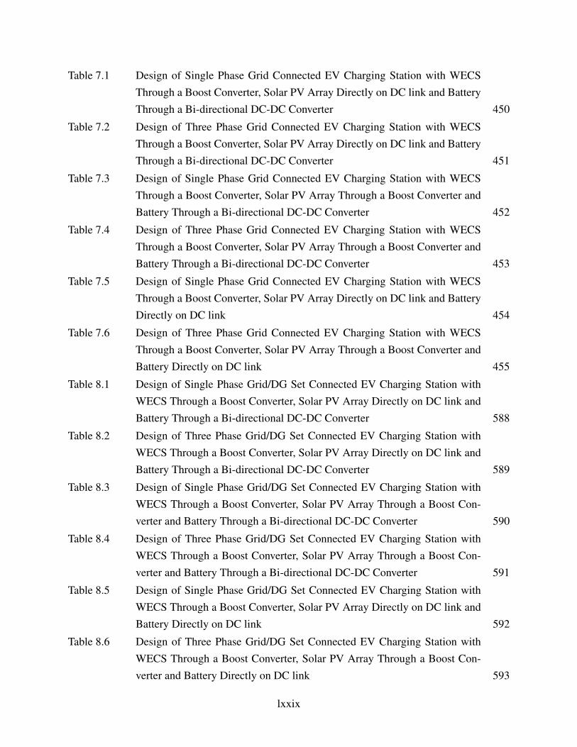
Table 7.1 Design of Single Phase Grid Connected EV Charging Station with WECSThrough a Boost Converter, Solar PV Array Directly on DC link and BatteryThrough a Bi-directional DC-DC Converter 450
Table 7.2 Design of Three Phase Grid Connected EV Charging Station with WECSThrough a Boost Converter, Solar PV Array Directly on DC link and BatteryThrough a Bi-directional DC-DC Converter 451
Table 7.3 Design of Single Phase Grid Connected EV Charging Station with WECSThrough a Boost Converter, Solar PV Array Through a Boost Converter andBattery Through a Bi-directional DC-DC Converter 452
Table 7.4 Design of Three Phase Grid Connected EV Charging Station with WECSThrough a Boost Converter, Solar PV Array Through a Boost Converter andBattery Through a Bi-directional DC-DC Converter 453
Table 7.5 Design of Single Phase Grid Connected EV Charging Station with WECSThrough a Boost Converter, Solar PV Array Directly on DC link and BatteryDirectly on DC link 454
Table 7.6 Design of Three Phase Grid Connected EV Charging Station with WECSThrough a Boost Converter, Solar PV Array Through a Boost Converter andBattery Directly on DC link 455
Table 8.1 Design of Single Phase Grid/DG Set Connected EV Charging Station withWECS Through a Boost Converter, Solar PV Array Directly on DC link andBattery Through a Bi-directional DC-DC Converter 588
Table 8.2 Design of Three Phase Grid/DG Set Connected EV Charging Station withWECS Through a Boost Converter, Solar PV Array Directly on DC link andBattery Through a Bi-directional DC-DC Converter 589
Table 8.3 Design of Single Phase Grid/DG Set Connected EV Charging Station withWECS Through a Boost Converter, Solar PV Array Through a Boost Con-verter and Battery Through a Bi-directional DC-DC Converter 590
Table 8.4 Design of Three Phase Grid/DG Set Connected EV Charging Station withWECS Through a Boost Converter, Solar PV Array Through a Boost Con-verter and Battery Through a Bi-directional DC-DC Converter 591
Table 8.5 Design of Single Phase Grid/DG Set Connected EV Charging Station withWECS Through a Boost Converter, Solar PV Array Directly on DC link andBattery Directly on DC link 592
Table 8.6 Design of Three Phase Grid/DG Set Connected EV Charging Station withWECS Through a Boost Converter, Solar PV Array Through a Boost Con-verter and Battery Directly on DC link 593
lxxix

Table 8.7 Design of Grid/DG Set Connected and Battery Supported EV charging Sta-tion 629
Table 9.1 Quantitative Performance of Charging Station Configurations in Terms ofTHDs 714
lxxx
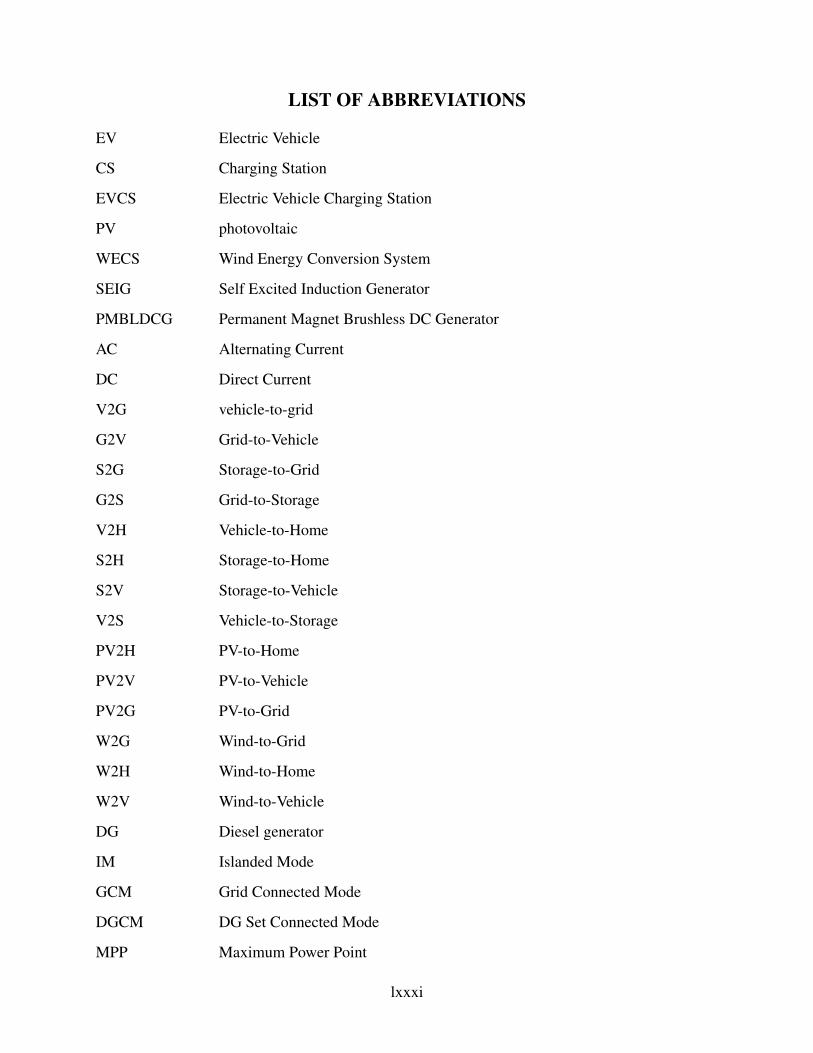
LIST OF ABBREVIATIONS
EV Electric Vehicle
CS Charging Station
EVCS Electric Vehicle Charging Station
PV photovoltaic
WECS Wind Energy Conversion System
SEIG Self Excited Induction Generator
PMBLDCG Permanent Magnet Brushless DC Generator
AC Alternating Current
DC Direct Current
V2G vehicle-to-grid
G2V Grid-to-Vehicle
S2G Storage-to-Grid
G2S Grid-to-Storage
V2H Vehicle-to-Home
S2H Storage-to-Home
S2V Storage-to-Vehicle
V2S Vehicle-to-Storage
PV2H PV-to-Home
PV2V PV-to-Vehicle
PV2G PV-to-Grid
W2G Wind-to-Grid
W2H Wind-to-Home
W2V Wind-to-Vehicle
DG Diesel generator
IM Islanded Mode
GCM Grid Connected Mode
DGCM DG Set Connected Mode
MPP Maximum Power Point
lxxxi
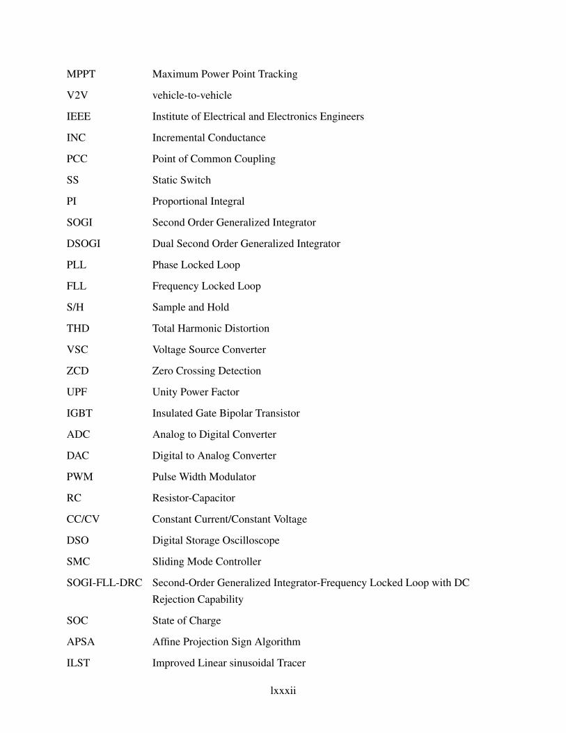
MPPT Maximum Power Point Tracking
V2V vehicle-to-vehicle
IEEE Institute of Electrical and Electronics Engineers
INC Incremental Conductance
PCC Point of Common Coupling
SS Static Switch
PI Proportional Integral
SOGI Second Order Generalized Integrator
DSOGI Dual Second Order Generalized Integrator
PLL Phase Locked Loop
FLL Frequency Locked Loop
S/H Sample and Hold
THD Total Harmonic Distortion
VSC Voltage Source Converter
ZCD Zero Crossing Detection
UPF Unity Power Factor
IGBT Insulated Gate Bipolar Transistor
ADC Analog to Digital Converter
DAC Digital to Analog Converter
PWM Pulse Width Modulator
RC Resistor-Capacitor
CC/CV Constant Current/Constant Voltage
DSO Digital Storage Oscilloscope
SMC Sliding Mode Controller
SOGI-FLL-DRC Second-Order Generalized Integrator-Frequency Locked Loop with DCRejection Capability
SOC State of Charge
APSA Affine Projection Sign Algorithm
ILST Improved Linear sinusoidal Tracer
lxxxii

CAPSA Convex Combined Affine Projection Sign Algorithm
DPF Displacement Power Factor
SS-LMSE Variable Step Size Least Mean Switching Error
ANC Adaptive Notch Cancellation
VLLMS Variable Leaky Least Mean Square
AFF-SOGI-DRC Adaptive Frequency Fixed Second Order Generalized Integrator with DCOffset Rejection Capability
lxxxiii
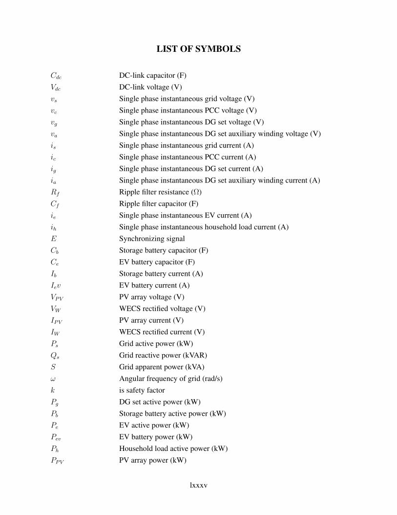
LIST OF SYMBOLS
Cdc DC-link capacitor (F)Vdc DC-link voltage (V)vs Single phase instantaneous grid voltage (V)vc Single phase instantaneous PCC voltage (V)vg Single phase instantaneous DG set voltage (V)va Single phase instantaneous DG set auxiliary winding voltage (V)is Single phase instantaneous grid current (A)ic Single phase instantaneous PCC current (A)ig Single phase instantaneous DG set current (A)ia Single phase instantaneous DG set auxiliary winding current (A)Rf Ripple filter resistance (Ω)Cf Ripple filter capacitor (F)ie Single phase instantaneous EV current (A)ih Single phase instantaneous household load current (A)E Synchronizing signalCb Storage battery capacitor (F)Ce EV battery capacitor (F)Ib Storage battery current (A)Iev EV battery current (A)VPV PV array voltage (V)VW WECS rectified voltage (V)IPV PV array current (V)IW WECS rectified current (V)Ps Grid active power (kW)Qs Grid reactive power (kVAR)S Grid apparent power (kVA)ω Angular frequency of grid (rad/s)k is safety factorPg DG set active power (kW)Pb Storage battery active power (kW)Pe EV active power (kW)Pev EV battery power (kW)Ph Household load active power (kW)PPV PV array power (kW)
lxxxv
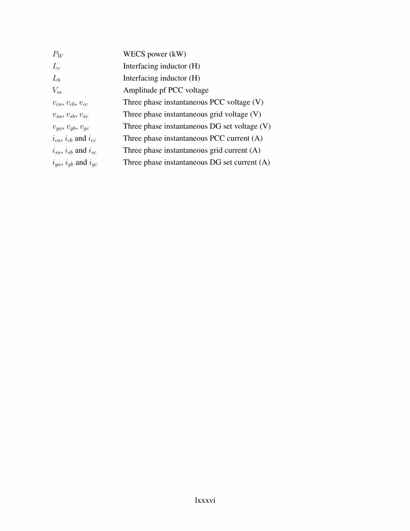
PW WECS power (kW)Lc Interfacing inductor (H)Lb Interfacing inductor (H)Vm Amplitude pf PCC voltagevca, vcb, vcc Three phase instantaneous PCC voltage (V)vsa, vsb, vsc Three phase instantaneous grid voltage (V)vga, vgb, vgc Three phase instantaneous DG set voltage (V)ica, icb and icc Three phase instantaneous PCC current (A)isa, isb and isc Three phase instantaneous grid current (A)iga, igb and igc Three phase instantaneous DG set current (A)
lxxxvi
![NOTICE - Chhattisgarh High Courtcghighcourt.nic.in/causelists/090514.pdf · singh,sumit verma,raghvendra verma,mala verma,anuradha verma / a.g. [ for further hearing ] [along with](https://img.pdfslide.net/doc/110x75/5fbf4f4afbfa7a76fb42cccf/notice-chhattisgarh-high-singhsumit-vermaraghvendra-vermamala-vermaanuradha.jpg)