Embed Size (px)
Citation preview
RISK ASSESSMENT FOR THE PROPOSED ANKERLIG CCGT CONVERSION PROJECT AT ATLANTIS,
WESTERN CAPE
RisCom (Pty)Ltd © Page 5-10
Report No.: R/08/SAV-01 Rev 0
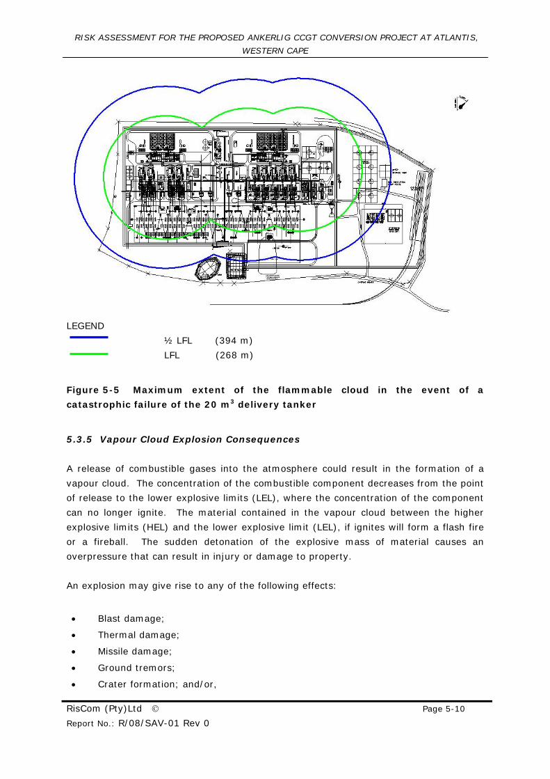
LEGEND
½ LFL (394 m)
LFL (268 m)
Figure 5-5 Maximum extent of the flammable cloud in the event of a
catastrophic failure of the 20 m3 delivery tanker
5.3.5 Vapour Cloud Explosion Consequences
A release of combustible gases into the atmosphere could result in the formation of a
vapour cloud. The concentration of the combustible component decreases from the point
of release to the lower explosive limits (LEL), where the concentration of the component
can no longer ignite. The material contained in the vapour cloud between the higher
explosive limits (HEL) and the lower explosive limit (LEL), if ignites will form a flash fire
or a fireball. The sudden detonation of the explosive mass of material causes an
overpressure that can result in injury or damage to property.
An explosion may give rise to any of the following effects:
• Blast damage;
• Thermal damage;
• Missile damage;
• Ground tremors;
• Crater formation; and/or,
RISK ASSESSMENT FOR THE PROPOSED ANKERLIG CCGT CONVERSION PROJECT AT ATLANTIS,
WESTERN CAPE
RisCom (Pty)Ltd © Page 5-11
Report No.: R/08/SAV-01 Rev 0
• Personal injury
These obviously depend on the pressure waves and proximity to the actual explosion. Of
concern in this investigation are the “far distance” effects, such as limited structural
damage and the breakage of windows, rather than crater formations.
RISK ASSESSMENT FOR THE PROPOSED ANKERLIG CCGT CONVERSION PROJECT AT ATLANTIS,
WESTERN CAPE
RisCom (Pty)Ltd © Page 5-12
Report No.: R/08/SAV-01 Rev 0
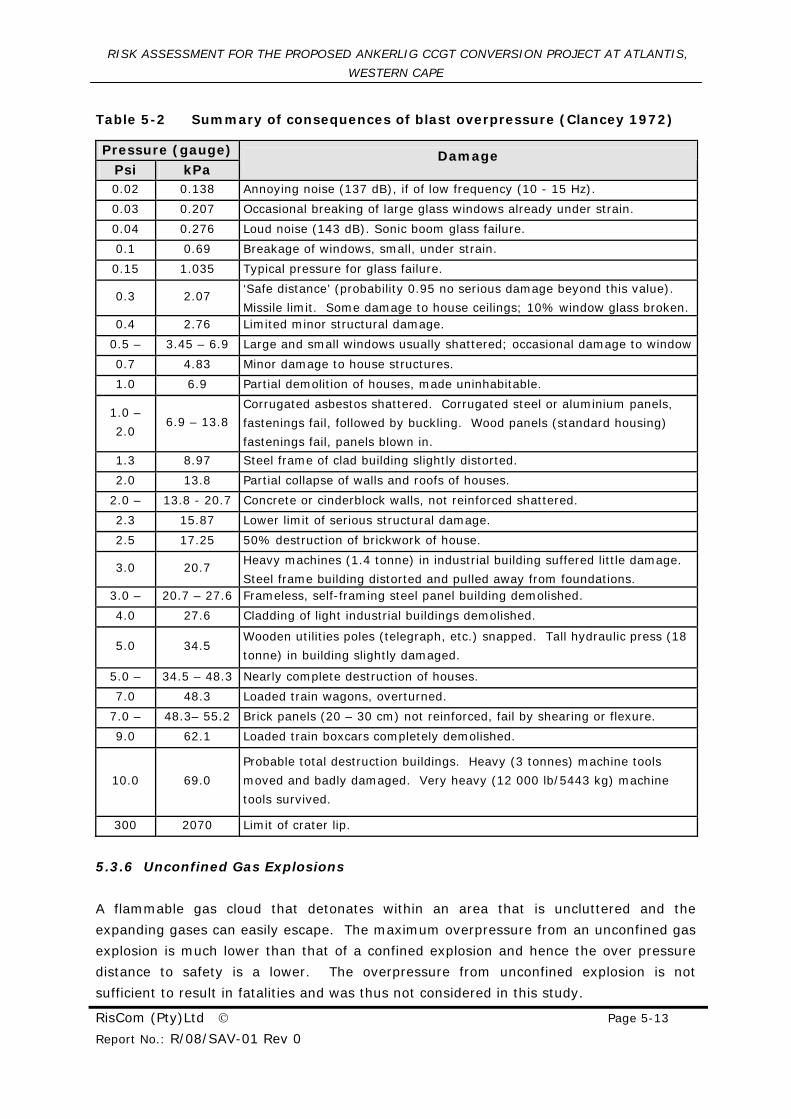
Table 5-2 and give a more detailed summary of the damage produced by an explosion
for various over-pressures. The most commonly used overpressure is the “0.3 psi”
value. This corresponds to a “Safe Distance”, at which approximately 10% of glass
windows are broken.
RISK ASSESSMENT FOR THE PROPOSED ANKERLIG CCGT CONVERSION PROJECT AT ATLANTIS,
WESTERN CAPE
RisCom (Pty)Ltd © Page 5-13
Report No.: R/08/SAV-01 Rev 0
Table 5-2 Summary of consequences of blast overpressure (Clancey 1972)
Pressure (gauge) Psi kPa
Damage
0.02 0.138 Annoying noise (137 dB), if of low frequency (10 - 15 Hz).
0.03 0.207 Occasional breaking of large glass windows already under strain.
0.04 0.276 Loud noise (143 dB). Sonic boom glass failure.
0.1 0.69 Breakage of windows, small, under strain.
0.15 1.035 Typical pressure for glass failure.
0.3 2.07 ‘Safe distance’ (probability 0.95 no serious damage beyond this value).
Missile limit. Some damage to house ceilings; 10% window glass broken. 0.4 2.76 Limited minor structural damage.
0.5 – 3.45 – 6.9 Large and small windows usually shattered; occasional damage to window
0.7 4.83 Minor damage to house structures.
1.0 6.9 Partial demolition of houses, made uninhabitable.
1.0 –
2.0 6.9 – 13.8
Corrugated asbestos shattered. Corrugated steel or aluminium panels,
fastenings fail, followed by buckling. Wood panels (standard housing)
fastenings fail, panels blown in.
1.3 8.97 Steel frame of clad building slightly distorted.
2.0 13.8 Partial collapse of walls and roofs of houses.
2.0 – 13.8 - 20.7 Concrete or cinderblock walls, not reinforced shattered.
2.3 15.87 Lower limit of serious structural damage.
2.5 17.25 50% destruction of brickwork of house.
3.0 20.7 Heavy machines (1.4 tonne) in industrial building suffered little damage.
Steel frame building distorted and pulled away from foundations. 3.0 – 20.7 – 27.6 Frameless, self-framing steel panel building demolished.
4.0 27.6 Cladding of light industrial buildings demolished.
5.0 34.5 Wooden utilities poles (telegraph, etc.) snapped. Tall hydraulic press (18
tonne) in building slightly damaged.
5.0 – 34.5 – 48.3 Nearly complete destruction of houses.
7.0 48.3 Loaded train wagons, overturned.
7.0 – 48.3– 55.2 Brick panels (20 – 30 cm) not reinforced, fail by shearing or flexure.
9.0 62.1 Loaded train boxcars completely demolished.
10.0 69.0
Probable total destruction buildings. Heavy (3 tonnes) machine tools
moved and badly damaged. Very heavy (12 000 lb/5443 kg) machine
tools survived.
300 2070 Limit of crater lip.
5.3.6 Unconfined Gas Explosions
A flammable gas cloud that detonates within an area that is uncluttered and the
expanding gases can easily escape. The maximum overpressure from an unconfined gas
explosion is much lower than that of a confined explosion and hence the over pressure
distance to safety is a lower. The overpressure from unconfined explosion is not
sufficient to result in fatalities and was thus not considered in this study.
RISK ASSESSMENT FOR THE PROPOSED ANKERLIG CCGT CONVERSION PROJECT AT ATLANTIS,
WESTERN CAPE
RisCom (Pty)Ltd © Page 5-14
Report No.: R/08/SAV-01 Rev 0
5.3.7 Confined Gas Explosion
A confined gas explosion is where the exploding gas is restricted from expanding by
physical barriers such as walls or equipment and obstacles. The confined gas explosions
were modelled using the multi energy model using the explosion class of 10. The multi-
energy model uses the energy available for explosions and setting the class between 1
and 10 can determine the effects of a weak deflagration to a confined detonation.
The proposed CCGT project would add structures to the site that would partially confine
the vapour cloud. A detonation with the confined flammable cloud could result in an
explosion
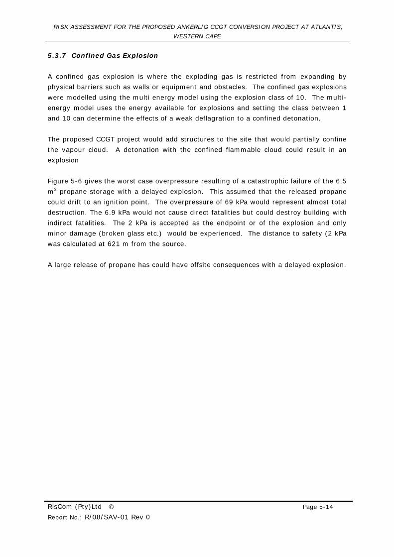
Figure 5-6 gives the worst case overpressure resulting of a catastrophic failure of the 6.5
m3 propane storage with a delayed explosion. This assumed that the released propane
could drift to an ignition point. The overpressure of 69 kPa would represent almost total
destruction. The 6.9 kPa would not cause direct fatalities but could destroy building with
indirect fatalities. The 2 kPa is accepted as the endpoint or of the explosion and only
minor damage (broken glass etc.) would be experienced. The distance to safety (2 kPa
was calculated at 621 m from the source.
A large release of propane has could have offsite consequences with a delayed explosion.
RISK ASSESSMENT FOR THE PROPOSED ANKERLIG CCGT CONVERSION PROJECT AT ATLANTIS,
WESTERN CAPE
RisCom (Pty)Ltd © Page 5-15
Report No.: R/08/SAV-01 Rev 0
LEGEND OVERPRESSURE
(kPa/psi)
2/0,3
6.9/1
69/10
Figure 5-6 Worst case blast overpressure from a confined vapour cloud
explosion from a catastrophic rupture of the 6.5 m3 storage vessels
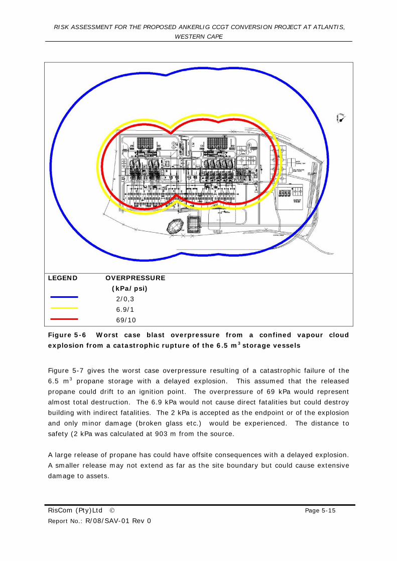
Figure 5-7 gives the worst case overpressure resulting of a catastrophic failure of the
6.5 m3 propane storage with a delayed explosion. This assumed that the released
propane could drift to an ignition point. The overpressure of 69 kPa would represent
almost total destruction. The 6.9 kPa would not cause direct fatalities but could destroy
building with indirect fatalities. The 2 kPa is accepted as the endpoint or of the explosion
and only minor damage (broken glass etc.) would be experienced. The distance to
safety (2 kPa was calculated at 903 m from the source.
A large release of propane has could have offsite consequences with a delayed explosion.
A smaller release may not extend as far as the site boundary but could cause extensive
damage to assets.
RISK ASSESSMENT FOR THE PROPOSED ANKERLIG CCGT CONVERSION PROJECT AT ATLANTIS,
WESTERN CAPE
RisCom (Pty)Ltd © Page 5-16
Report No.: R/08/SAV-01 Rev 0
LEGEND OVERPRESSURE
(kPa/psi)
2/0,3
6.9/1
69/10
Figure 5-7 Worst case blast overpressure from a confined vapour cloud
explosion from a catastrophic rupture of the 20 m3 storage vessels
5.4 Boiling Liquid Expanding Vapour Explosion (BLEVE)
A Boiling Liquid Expanding Vapour Explosion (BLEVE) can occur when a flame impinges
on the condensate tankers, particularly in the vapour space region where cooling by
evaporation of the contained fluid does not occur. The vessel shell weakens, ruptures
with a total loss of contents and the issuing mass of material burns as a massive fireball.
A Boiling Liquid Expanding Vapour Explosion (BLEVE) can occur when a flame impinges
on a propane pressure vessel, particularly in the vapour space region where cooling by
evaporation of the contained LPG does not occur. The vessel shell weakens, ruptures
with a total loss of contents, and the issuing mass of propane burns as a massive
fireball.
RISK ASSESSMENT FOR THE PROPOSED ANKERLIG CCGT CONVERSION PROJECT AT ATLANTIS,
WESTERN CAPE
RisCom (Pty)Ltd © Page 5-17
Report No.: R/08/SAV-01 Rev 0
The major consequences of a BLEVE are the intense thermal radiation from the fireball, a
blast wave and fragments from the shattered vessel. These fragments may be projected
to considerable distances. Analyses of the travel range of fragment missiles from a
number of BLEVE’s suggest that the majority land within 700 m from the incident. A
blast wave from a BLEVE is fairly localised, but can cause significant damage to
immediate equipment.
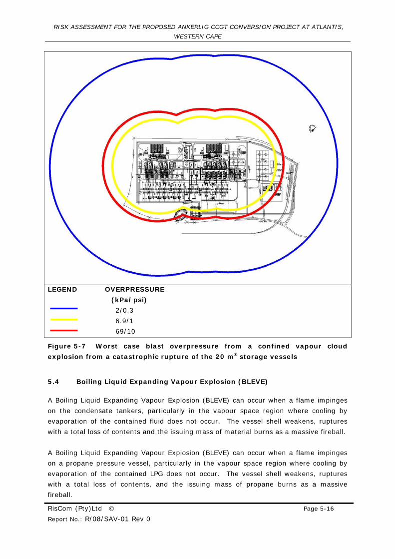
A BLEVE formed from the 6.5 m3 propane storage assumed a flammable and explosive
mass of 3192 kg. On explosion the radius of the fireball was estimated to be 44.6 m,
with duration of 6.94 seconds. The lift-off height was calculated to be 89.2 m. The
thermal radiation from the resulting fireball is shown below in Figure 5-8. Due to the
relatively short duration the thermal radiation consequence on health must be evaluated
with respect to the duration time. The 1% lethality for the exposed duration equates to
21.8 kW/m2 (86 m from exploding vessel and a 10% fatality would be 29.5 kW/m2 (60 m
from exploding vessel). The 100% fatality of 150 kW/m2 was not reached. The
consequences of a BLEVE fireball from a 6.5 m3 storage vessel would not extend beyond
the site boundary and thus no further analysis would be required.
LEGEND THERMAL RADIATION
(kW/m2)
21.7 (1% Fatality)
29.5 (10% Fatality)
Figure 5-8 Thermal radiation from a BLEVE of the propane storage tank
RISK ASSESSMENT FOR THE PROPOSED ANKERLIG CCGT CONVERSION PROJECT AT ATLANTIS,
WESTERN CAPE
RisCom (Pty)Ltd © Page 5-18
Report No.: R/08/SAV-01 Rev 0
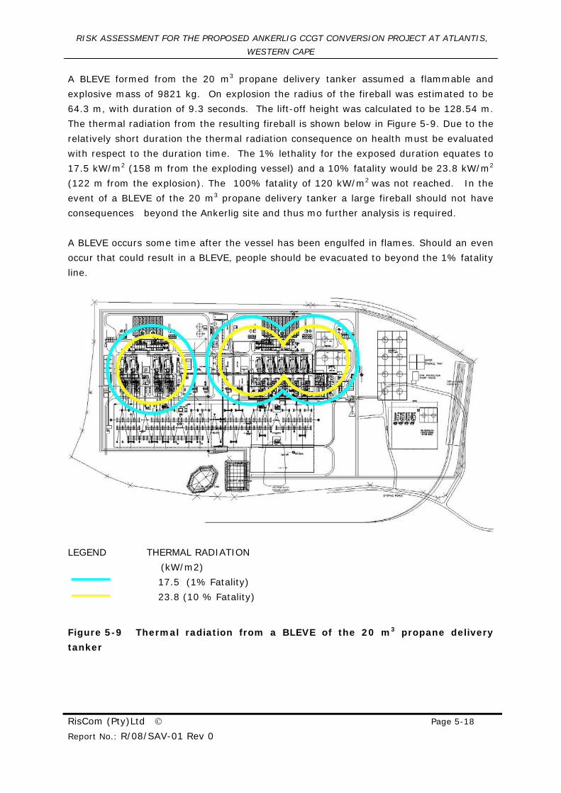
A BLEVE formed from the 20 m3 propane delivery tanker assumed a flammable and
explosive mass of 9821 kg. On explosion the radius of the fireball was estimated to be
64.3 m, with duration of 9.3 seconds. The lift-off height was calculated to be 128.54 m.
The thermal radiation from the resulting fireball is shown below in Figure 5-9. Due to the
relatively short duration the thermal radiation consequence on health must be evaluated
with respect to the duration time. The 1% lethality for the exposed duration equates to
17.5 kW/m2 (158 m from the exploding vessel) and a 10% fatality would be 23.8 kW/m2
(122 m from the explosion). The 100% fatality of 120 kW/m2 was not reached. In the
event of a BLEVE of the 20 m3 propane delivery tanker a large fireball should not have
consequences beyond the Ankerlig site and thus mo further analysis is required.
A BLEVE occurs some time after the vessel has been engulfed in flames. Should an even
occur that could result in a BLEVE, people should be evacuated to beyond the 1% fatality
line.
LEGEND THERMAL RADIATION
(kW/m2)
17.5 (1% Fatality)
23.8 (10 % Fatality)
Figure 5-9 Thermal radiation from a BLEVE of the 20 m3 propane delivery
tanker
RISK ASSESSMENT FOR THE PROPOSED ANKERLIG CCGT CONVERSION PROJECT AT ATLANTIS,
WESTERN CAPE
RisCom (Pty)Ltd © Page 6-1
Report No.: R/08/SAV-01 Rev 0
6 RISK CALCULATIONS
The previous sections dealt specifically with the predicted zone of impact without taking
into account the probability of occurrence and the combined impacts. Risk; on the other
hand is a product of the likelihood of occurrence and the consequences.
The risk calculations need to include the effect of wind speed and atmospheric
turbulence. The accidental spills were simulated using a wind speed of 10 m/s in equal
frequencies from all directions.
The risk parameter used in this assessment was maximum individual risk to give an
assessment of the risks posed by the preliminary designs.
6.1 Maximum Individual Risk Parameter
Individual risk parameters include “Average Individual Risk”, “Weighted Individual Risk”,
“Maximum Individual Risk” and “Fatal Accident Rate (FAR)”. The latter parameter is
more applicable to occupational exposures. Only the Maximum Individual Risk (MIR) will
be used in this assessment. For this parameter, the frequency of fatality is calculated for
an individual who is presumed to be present at some specified location. The parameter
is not dependent on the knowledge of the population at risk, and so is an easier
parameter to use in the predictive mode than the Average Individual and Weighted
Individual risks. The unit of measure is fatality risk per person per year.
6.1.1 Acceptable Risks
The next step after having characterised a risk and obtained a risk level, is to
recommend whether the outcome is acceptable. In contrast to the employees in a plant,
which may be assumed healthy, the adopted exposure assessment applies to an average
population group that also includes sensitive sub-populations. Sensitive sub-population
groups are those people that for reasons of age or medical condition have a greater than
normal response to contaminants. Health guidelines and standards used to establish risk
normally incorporate safety factors that address this group.
Among the most difficult tasks of risk characterisation is the definition of an acceptable
risk. An attempt to account for risks in manner similar to those used in everyday life,
the UK HSE developed the “risk ALARP triangle”. This involved deciding:
• Whether a risk is so high that something must be done about it;
• Whether the risk is, or has been made, so small that no further precautions are
necessary; or
RISK ASSESSMENT FOR THE PROPOSED ANKERLIG CCGT CONVERSION PROJECT AT ATLANTIS,
WESTERN CAPE
RisCom (Pty)Ltd © Page 6-2
Report No.: R/08/SAV-01 Rev 0
• If a risk falls between these two states, that it has been reduced to levels as low
as reasonably practicable (ALARP).
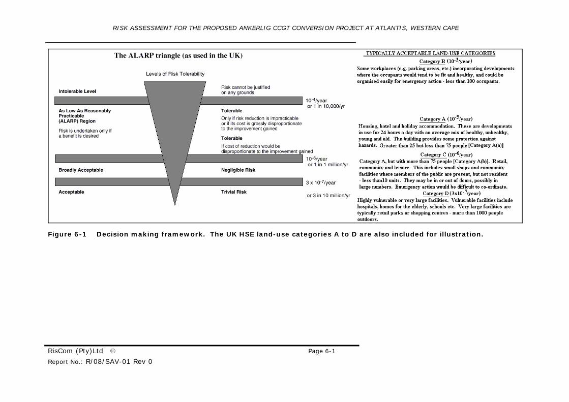
This is illustrated graphically, in Figure 6-1.
ALARP stands for “As Low As Reasonably Practicable”. As used in the UK, it is the region
between that which is intolerable, at 1x10⁻⁴ per year, and broadly acceptable level of
1x10⁻⁶ per year, with a further lower level of risk of 3x10⁻⁷ per year being applied to
either vulnerable or very large populations for land use planning.
RISK ASSESSMENT FOR THE PROPOSED ANKERLIG CCGT CONVERSION PROJECT AT ATLANTIS, WESTERN CAPE
RisCom (Pty)Ltd © Page 6-1
Report No.: R/08/SAV-01 Rev 0
Figure 6-1 Decision making framework. The UK HSE land-use categories A to D are also included for illustration.
RISK ASSESSMENT FOR THE PROPOSED ANKERLIG CCGT CONVERSION PROJECT AT ATLANTIS,
WESTERN CAPE
RisCom (Pty)Ltd © Page 6-1
Report No.: R/08/SAV-01 Rev 0
6.2 Accidental Fire Scenarii
Relatively large quantities of flammable and combustible material are stored at Gas-1
site, Atlantis. These flammable materials stored and transported at various places on
the site may ignite and develop into large fire under suitable conditions.
6.2.1 Pool Fires
A pool fire will occur when pool of combustible material ignites. The cause of this is
usually due to an unexpected spillage or leak. As spillages are collected in bunds, the
pool fires are most likely to take place within the bunded areas of the storage, filling and
loading areas. The simulations were completed for the following scenario summarised in
Appendix D.
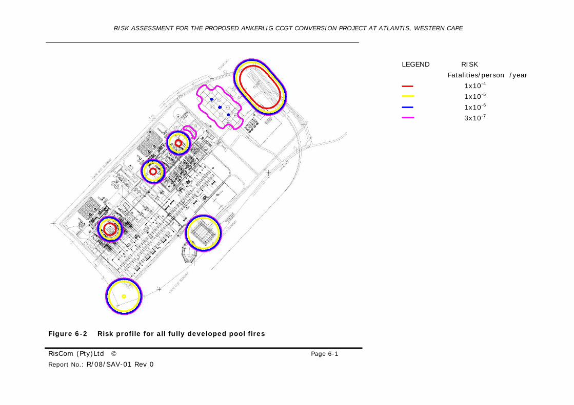
The risk isopleths are shown below in Figure 6-2. The 1x10⁻⁶ fatality per person isopleth
reaches the boundary of the site and would qualify the site as a Major Hazardous
Installation. The off-site risks of greater than 1x10⁻⁴ fatalities per person per year are
greater than the acceptable range and would be considered intolerable.
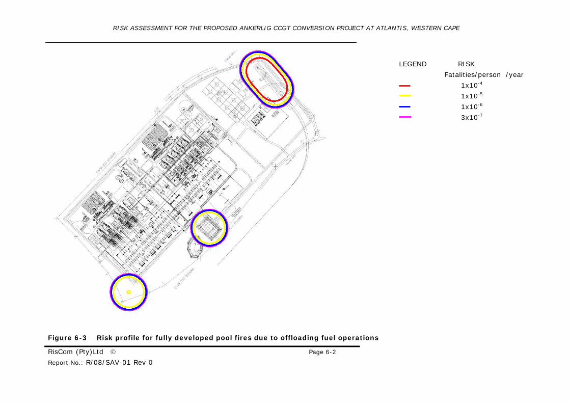
The major contributing factor to the isopleth distances is the offloading risks as shown
Figure 6-3. The risks were calculated at the maximum continuous rate for the Power
Station operating 24 hours per day. The split between road and rail was unknown and
thus the road offloading assumed the maximum offloading rate while the rail assumed
full supply of fuel would be delivered by rail. This study thus considers some double
counting reflected the maximum risk isopleths. For the rail offloading no spill
containment was assumed giving a large pool fire area reflected in the risk calculations.
As the 1x10⁻⁴ fatalities per person per year lies a short distance over the boundary there
is possibility to reduce risks to acceptable levels. Reduction of risk is discussed in
Chapter 7.
Lube oil is extremely difficult to ignite and has acceptable risks.
RISK ASSESSMENT FOR THE PROPOSED ANKERLIG CCGT CONVERSION PROJECT AT ATLANTIS, WESTERN CAPE
RisCom (Pty)Ltd © Page 6-1
Report No.: R/08/SAV-01 Rev 0
LEGEND RISK
Fatalities/person /year
1x10⁻⁴
1x10⁻⁵
1x10⁻⁶
3x10⁻⁷
Figure 6-2 Risk profile for all fully developed pool fires
RISK ASSESSMENT FOR THE PROPOSED ANKERLIG CCGT CONVERSION PROJECT AT ATLANTIS, WESTERN CAPE
RisCom (Pty)Ltd © Page 6-2
Report No.: R/08/SAV-01 Rev 0
LEGEND RISK
Fatalities/person /year
1x10⁻⁴
1x10⁻⁵
1x10⁻⁶
3x10⁻⁷
Figure 6-3 Risk profile for fully developed pool fires due to offloading fuel operations
RISK ASSESSMENT FOR THE PROPOSED ANKERLIG CCGT CONVERSION PROJECT AT ATLANTIS,
WESTERN CAPE
RisCom (Pty)Ltd © Page 6-1
Report No.: R/08/SAV-01 Rev 0
6.2.2 Jet Fires
Jet fires do not have consequences beyond the boundary of the site and thus the risks
are acceptable
6.2.3 Flash Fires
The only scenario that could result in a flammable cloud extending beyond the site
boundary would be a catastrophic failure of the propane delivery tanker. Due to the
small amount of time the propane delivery tanker spends on site, accompanied by the
catastrophic failure rate of the tanker at 5x10⁻⁷ events per year, the risks of flash fires
would be considered trivial.
6.3 Explosion Risk
A large propane gas release could drift into a congested that in contact with an ignition
source could detonate the flammable mass. Explosions with offsite consequences
require a large release of propane. The probability of a pressure vessel tank failure
accompanied by a detonation would be less than 3 x10⁻⁷ events per annum and would be
considered acceptable.
Maintenance of pressure vessels is regulated and statutory testing is required to keep
vessels in good operating condition. T hus the failure frequency used for pressure
vessels in this report would be accurate providing the site is fully compliant to all
statutory legislation relating pressure vessels and pressurised systems.
RISK ASSESSMENT FOR THE PROPOSED ANKERLIG CCGT CONVERSION PROJECT AT ATLANTIS,
WESTERN CAPE
RisCom (Pty)Ltd © Page 7-1
Report No.: R/08/SAV-01 Rev 0
7 REDUCTION OF RISK
From the simulations performed, a number of events have risks sufficiently high to
consider mitigation. Mitigation which could be considered to reduce this risk includes,
but is not limited to the following:
7.1 Plant Layout
Layout and separation distances must be done with care to prevent injuries and damage
due to accidental fires. The following codes should be used as the minimum specification
in terms of plant layout, safety distances, secondary containment and related issues:
• SANS 10089 Part 1 (formally SABS 089-1) is specific to the storage of
large volumes of petroleum products.
• SANS 10087 Part 3 (formally SABS 087-3) is specific to the storage of
LPG products
These codes should be used as the minimum specification in terms of plant layout, safety
distances, secondary containment and related issues.
7.2 Bund Height
The bund wall height of the diesel storage tanks is specified at exceeds 1.8 m. A bund
wall height of over 1.8 m requires special requirements in accordance to the SANS
10089 Part 1, code as it contains additional hazards. It is recommended that the bund
wall height be reviewed in light of the code or additional safety measures be introduced.
7.3 Process Hazard Analysis (PHA)
A detailed Process Hazard Analysis (PHA) such as a Hazop study should be completed
prior to construction of the project, with all potential hazards identified, including fuel
and any other substances, and sufficient mitigation suggested for safe operation.
7.4 Overfilling of Fuel Tanks
The prevention of potential overfilling of the fuel storage tanks should be addressed to
meet acceptable levels of risk. This can be done with adequate instrumentation and/or
operating procedures.
7.5 Rail Offloading
Large spillages need to be contained and if possible be directed away from the offloading
vessels. Fire protection and fighting of the spilt diesel must be achievable at the location
RISK ASSESSMENT FOR THE PROPOSED ANKERLIG CCGT CONVERSION PROJECT AT ATLANTIS,
WESTERN CAPE
RisCom (Pty)Ltd © Page 7-2
Report No.: R/08/SAV-01 Rev 0
of the contained material. Secondary containment at a remote location may address
these issues.
RISK ASSESSMENT FOR THE PROPOSED ANKERLIG CCGT CONVERSION PROJECT AT ATLANTIS,
WESTERN CAPE
RisCom (Pty)Ltd © Page 8-1
Report No.: R/08/SAV-01 Rev 0
8 CONCLUSIONS
Risk calculations are not precise. The accuracy of the predictions is determined by the
quality of base data and expert judgements
The risk assessment was done on the assumption that the site will be maintained to an
acceptable level and that all-statuary regulations will be applied. It was also assumed
that the detailed engineering designs will be performed by competent people and that the
plant requirements will be correctly specified for the intended duty.
A number of incident scenarios were considered and the following conclusions were
reached.
8.1 Pool Fires
Large bund fires and pool fires from spillages from road and rail offloading operations
were calculated for the Ankerlig Power Station and the proposed CCGT conversion. The
study concluded that Ankerlig Power station an the OCGT conversion could have impacts
a short distance beyond the site boundary.
The risks from pool and bund fires of 1x10⁻⁶ fatalities per person, which is generally
considered as tolerable, extended beyond the site’s boundary and in some instances
were excessive.
As the 1x10⁻⁴ fatalities per person per year lies a short distance over the boundary there
is possibility to reduce risks to acceptable levels with engineering and administrative
controls.
8.2 Jet fires
Jet fires from a release of pressurised propane would form a maximum flame length of
20.4 m. This flame would not extend beyond the site’s boundary but could injure people
and damage equipment within the flame.
8.3 Explosions
As a result in additional structures for the CCGT conversion, a large lease of propane
could result in a partial confined explosion that could extend beyond the site’s boundary.
However the risks for offsite fatalities are considered acceptable.
RISK ASSESSMENT FOR THE PROPOSED ANKERLIG CCGT CONVERSION PROJECT AT ATLANTIS,
WESTERN CAPE
RisCom (Pty)Ltd © Page 8-2
Report No.: R/08/SAV-01 Rev 0
8.4 Major Hazardous Installation
This investigation concluded that the CCGT conversion would have risk excessive of 1x10-
6 fatalities per person per year at the site boundary and would classify the facility as a
Major Hazardous Installation. While there is potential to reduce the impacts and risks, a
quantitative risk assessment would be required in terms of the Major Hazardous
Installation (MHI) Regulations (July 2001) prior to project construction. The risk
assessment must be done with final designs and layouts. Exemption from completing a
MHI risk assessment can not be done at this stage as designs are preliminary and subject
to change.
RISK ASSESSMENT FOR THE PROPOSED ANKERLIG CCGT CONVERSION PROJECT AT ATLANTIS,
WESTERN CAPE
RisCom (Pty)Ltd © Page 9-1
Report No.: R/08/SAV-01 Rev 0
9 RECOMMENDATIONS
As a result of the risk assessment study conducted for the fuel storage facility for the
proposed OCGT conversion , the following recommendations are made:
9.1 Major Hazardous Installation Risk Assessment
As offsite consequences are possible, a quantitative risk assessment would be required in
terms of the Major Hazardous Installation (MHI) Regulations (July 2001) prior to project
construction. The risk assessment must be done by an Approved Inspection Authority,
as recognised by the Department of Labour, with final designs and layouts.
9.2 Project Approval
Large petrochemical storage facilities have been installed around the world having
acceptable risks. While consequences of the fuel storage facility may extend beyond the
sites’ boundaries, the risk can be engineered to within acceptable risks.
As a result of the risk assessment study conducted for the proposed CCGT conversion
project, no fatal flaws were apparent that could prevent the project proceeding. It is
thus recommended that the project proceed into the detailed phase of the design with
the following provisions:
vii. Compliance to all statutory requirements e.g. Vessel Under Pressure
Regulations etc.;
viii. Compliance with applicable SANS codes SANS 10087-3, SANS 10108. etc.;
ix. A recognised process hazard analysis (HAZOP, FMEA, etc) should be
completed for the proposed plant prior to construction. This is to ensure
design and operational hazards have been identified adequate mitigation put
in place. It would be preferable if study could be facilitated by an
independent party that can not benefit financially from offering services,
equipment or instrumentation for the project;
x. A safety document detailing safety and design features reducing the impacts
from fires, explosions and flammable atmospheres must be prepared and
issued to the MHI assessment body at the time of the MHI assessment. The
built facility can be audited against the safety document to ensure
compliance with the EIA Terms of Reference. Codes such as IEC 61511 can
be used to achieve these requirements. Eskom and their contractors must
demonstrate that sufficient mitigation has been included in the designs to
ensure the safety of the surrounding neighbours and the public.
xi. Emergency response documentation must be done with input from local
authorities; and;
RISK ASSESSMENT FOR THE PROPOSED ANKERLIG CCGT CONVERSION PROJECT AT ATLANTIS,
WESTERN CAPE
RisCom (Pty)Ltd © Page 9-2
Report No.: R/08/SAV-01 Rev 0
xii. A risk assessment in accordance to the prescribed Major Hazard Installation
(MHI) Regulations must be conducted after completion of the final designs
and layout, but prior to construction.
RISK ASSESSMENT FOR THE PROPOSED ANKERLIG CCGT CONVERSION PROJECT AT ATLANTIS,
WESTERN CAPE
RisCom (Pty)Ltd © Page 10-1
Report No.: R/08/SAV-01 Rev 0
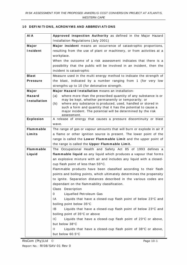
10 DEFINITIONS, ACRONYMS AND ABBREVIATIONS
AIA Approved inspection Authority as defined in the Major Hazard
Installation Regulations (July 2001)
Major
Incident
Major incident means an occurrence of catastrophic proportions,
resulting from the use of plant or machinery, or from activities at a
workplace.
When the outcome of a risk assessment indicates that there is a
possibility that the public will be involved in an incident, then the
incident is catastrophic
Blast
Pressure
Measure used in the multi energy method to indicate the strength of
the blast, indicated by a number ranging from 1 (for very low
strengths up to 10 (for detonative strength.
Major
Hazard
Installation
Major Hazard Installation means an installation-
(a) where more than the prescribed quantity of any substance is or may be kept, whether permanently or temporarily; or
(b) where any substance is produced, used, handled or stored in such a form and quantity that it has the potential to cause a major incident. The potential will be determined by the risk assessment.
Explosion A release of energy that causes a pressure discontinuity or blast
wave.
Flammable
Limits
The range of gas or vapour amounts that will burn or explode in air if
a flame or other ignition source is present. The lower point of the
range is called the Lower Flammable Limit and the upper point of
the range is called the Upper Flammable Limit.
Flammable
Liquid
The Occupational Health and Safety Act 85 of 1993 defines a
flammable liquid as any liquid which produces a vapour that forms
an explosive mixture with air and includes any liquid with a closed-
cup flash point of less than 55ºC.
Flammable products have been classified according to their flash
points and boiling points, which ultimately determines the propensity
to ignite. Separation distances described in the various codes are
dependant on the flammability classification.
Class Description
0 Liquefied Petroleum Gas
IA Liquids that have a closed-cup flash point of below 23°C and
boiling point below 35°C
IB Liquids that have a closed-cup flash point of below 23°C and
boiling point of 35°C or above
IC Liquids that have a closed-cup flash point of 23°C or above,
but below 38°C
II Liquids that have a closed-cup flash point of 38°C or above,
but below 60.5°C
RISK ASSESSMENT FOR THE PROPOSED ANKERLIG CCGT CONVERSION PROJECT AT ATLANTIS,
WESTERN CAPE
RisCom (Pty)Ltd © Page 10-2
Report No.: R/08/SAV-01 Rev 0
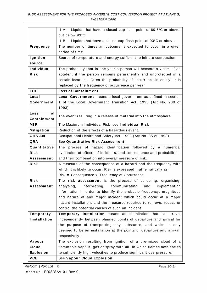
IIIA Liquids that have a closed-cup flash point of 60.5°C or above,
but below 93°C
IIIB Liquids that have a closed-cup flash point of 93°C or above
Frequency The number of times an outcome is expected to occur in a given
period of time.
Ignition
source
Source of temperature and energy sufficient to initiate combustion.
Individual
Risk
The probability that in one year a person will become a victim of an
accident if the person remains permanently and unprotected in a
certain location. Often the probability of occurrence in one year is
replaced by the frequency of occurrence per year
LOC Loss of Containment
Local
Government
Local Government means a local government as defined in section
1 of the Local Government Transition Act, 1993 (Act No. 209 of
1993)
Loss of
Containment The event resulting in a release of material into the atmosphere.
MIR The Maximum Individual Risk see Individual Risk
Mitigation Reduction of the effects of a hazardous event.
OHS Act Occupational Health and Safety Act, 1993 (Act No. 85 of 1993) QRA See Quantitative Risk Assessment
Quantitative
Risk
Assessment
The process of hazard identification followed by a numerical
evaluation of effects of incidents, and consequence and probabilities,
and their combination into overall measure of risk.
Risk A measure of the consequence of a hazard and the frequency with
which it is likely to occur. Risk is expressed mathematically as:
Risk = Consequence x Frequency of Occurrence
Risk
Assessment
The risk assessment is the process of collecting, organising,
analysing, interpreting, communicating and implementing
information in order to identify the probable frequency, magnitude
and nature of any major incident which could occur at a major
hazard installation, and the measures required to remove, reduce or
control the potential causes of such an incident.
Temporary
Installation
Temporary installation means an installation that can travel
independently between planned points of departure and arrival for
the purpose of transporting any substance, and which is only
deemed to be an installation at the points of departure and arrival,
respectively;
Vapour
Cloud
Explosion
The explosion resulting from ignition of a pre-mixed cloud of a
flammable vapour, gas or spray with air, in which flames accelerates
to sufficiently high velocities to produce significant overpressure.
VCE See Vapour Cloud Explosion
RISK ASSESSMENT FOR THE PROPOSED ANKERLIG CCGT CONVERSION PROJECT AT ATLANTIS,
WESTERN CAPE
RisCom (Pty)Ltd © Page 11-1
Report No.: R/08/SAV-01 Rev 0
11 REFERENCES
Clancey (1972). Diagnostic features of explosion damage. Sixth Int. Mtg of
Forensic Sciences, Edinburgh.
CPR 14 E (1997). Methods for the Calculation of Physical Effects (“Yellow Book”),
Third Edition, TNO, Apeldoorn.
CPR 16 E (1992). Methods for the Determination of Possible Damage (“Green
Book”), First Edition, TNO, Apeldoorn.
CPR 18E (1999), Guidelines for Quantitative Risk Assessment (“Purple Book”), First
Edition, TNO, Apeldoorn.
Cox A W, Lees F P and Ang ML (1990). Classification of Hazardous Locations, British
Institution of Chemical Engineers.
Lees F P (1980). Loss Prevention in the Process Industries, 1st Edition,
Butterworths, London, UK.
Lees F P (2001). Loss Prevention in the Process Industries: Hazard
Identification, Assessment, and Control, 2nd Edition, Butterworths, London, UK.
SANS 10089-1:2003 (SABS 089-1), The petroleum industry – Part 1: Storage and
distribution of petroleum products in above-ground bulk installations
SANS 10087-3: (formerly SABS 087-3), The handling, storage, and distribution of
liquefied petroleum gas in domestic, commercial and industrial installations
Part 3: Liquefied petroleum gas installations involving storage vessels of
individual water capacity exceeding 500 ℓ.
RISK ASSESSMENT FOR THE PROPOSED ANKERLIG CCGT CONVERSION PROJECT AT ATLANTIS,
WESTERN CAPE
RisCom (Pty)Ltd © Page 12-1
Report No.: R/08/SAV-01 Rev 0
12 APPENDIX A: NOTIFICATION OF PROPOSED MAJOR HAZARD INSTALLATION
Prior to the assessment of the potential impact of the various accidental spills, reference
needs to be made to the legislation, regulations and guidelines governing the operation
of the proposed development.
On 16 January 1998, the Major Hazard Installation Regulations was promulgated under
the Occupational Health and Safety Act 1993 (Act No 85 of 1993), with a further
amendment on 30 July 2001. The provisions of the regulations apply to installations,
which have on their premises a quantity of a substance, which can pose a significant risk
to the health, and safety of employees and the public.
The regulations essentially consists of six parts, namely
1. The duties for notification of a major hazard installation (existing or proposed),
including
a. Fixed (see Box A.1); and,
b. Temporary installations.
2. The minimum requirements for a quantitative risk assessment (see Box A.2);
3. The requirements of an on-site emergency plan (see Box A.3);
4. The reporting steps of risk and emergency occurrences (see Box A.4);
5. The general duties required of suppliers; and,
6. The general duties required of local government.
BOX A.1 - NOTIFICATION OF INSTALLATION
Applications need to be made in writing to the relevant local authority and the provincial
director for permission: To erect any major hazard installation.
Prior to the modification of any existing installation, which may significantly increase
the risk, related to it (e.g. increased storage or production capacity or alteration of
process).
Applications need to include the following information: Physical address of installation;
Complete material safety data sheets of all hazardous substances;
Maximum quantity of each substance envisaged to be on the premises at any one
time;
The risk assessment of the installation (see Box A.2); and,
Any further information that may be deemed necessary by an inspector in the
interests of health and safety to the public.
Applications need to be advertised in at least one newspaper serving the surrounding
communities, and by way of notices posted within these communities.
RISK ASSESSMENT FOR THE PROPOSED ANKERLIG CCGT CONVERSION PROJECT AT ATLANTIS,
WESTERN CAPE
RisCom (Pty)Ltd © Page 12-2
Report No.: R/08/SAV-01 Rev 0
BOX A.2 - THE RISK ASSESSMENT
• The risk assessment is the process of collecting, organising, analysing, interpreting, communicating and implementing information in order to identify the probable frequency, magnitude and nature of any major incident which could occur at a major hazard installation, and the measures required to remove, reduce or control the potential causes of such an incident.
• Risk assessments need to be undertaken at intervals not exceeding five years and need to be submitted to the relevant local emergency services.
• Copies of the risk assessment must be made available to the relevant health and safety committee, and give them 60 days within which to comment thereon and ensure that the results of the assessment be made available to the relevant representative or committee who may comment thereon.
• Risk assessments should be undertaken by competent person(s) and include the following: General process description;
Description of major incidents associated with this type of installation and the consequences of such incidents (including potential incidents);
Estimate of the probability of a major incident;
The on site emergency plan;
Estimate the total result in the case of an explosion;
Estimate of the effects of thermal radiation in the case of fire;
Estimate concentration effects in the case of a toxic release;
Potential effect of a major incident at one major hazard installation on an adjacent major hazard installation or part thereof;
Potential effect of a major incident on any other installation, members of the public (including all persons outside the premises) and on residential areas;
Meteorological tendencies;
Suitability of existing emergency procedures for the risks identified;
Any requirements laid down in terms of the Environmental Conservation Act, 1989 (Act No. 73 of 1989); and,
Any organisational measures that may be required.
• The employer shall ensure that the risk assessment is of an acceptable standard and is reviewed should:
It be suspected that the preceding assessment is no longer valid;
Changes in the process affect hazardous substances;
Changes in the process involve a substance resulting in the installation being classified a major hazardous installation or in the methods, equipment or procedures in the sue, handling or processing of that substance; or,
Incidents that have brought the emergency plan into operation may affect the existing risk assessment.
• Risks assessment must be made available for scrutiny by any interested or affected person that may be affected by the activities, at a time, place and in a manner agreed upon between the parties.
RISK ASSESSMENT FOR THE PROPOSED ANKERLIG CCGT CONVERSION PROJECT AT ATLANTIS,
WESTERN CAPE
RisCom (Pty)Ltd © Page 12-3
Report No.: R/08/SAV-01 Rev 0
BOX A.3 – ON-SITE EMERGENCY PLAN
After submission of the notification, the following shall be established: An on-site emergency plan must be available which is to be followed inside the
premises of the installation or part of the installation classified as a major hazard
installation in consultation with the relevant health and safety representative or the
relevant health and safety committee.
The emergency plan must be discussed with the relevant local government taking
into consideration any comment on the risk related to the health and safety of the
public.
The on-site emergency plan has to be reviewed and, where necessary, update the plan,
in consultation with the relevant local government, at least once every three years. A copy of the on-site emergency plan shall be signed in the presence of two
witnesses, who shall attest the signature.
Ensure that the on-site emergency plan is readily available at all times for
implementation and use.
Ensure that all employees are conversant with the on-site emergency plan.
Cause the on-site emergency plan to be tested in practice at least once a year and keep
a record of such test.
Any employer, self-employed person and user owning or in control of a pipeline that
could pose a threat to the general public shall inform the relevant local government and
shall be jointly responsible with the relevant government for the establishment and
implementation of an on-site emergency plan.
BOX A.4 – Reporting of Risk and Emergency Occurrences
Following and emergency occurrence, the user of the installation shall: Subject to the provisions of regulation 6 of the General Administrative Regulations,
within 48 hours by means of telephone, facsimile or similar means of
communication inform the chief inspector, the provincial director and relevant local
government of the occurrence of a major incident or an incident that brought the
emergency plan into operation or any near miss.
Submit a report in writing to the chief inspector, provincial director and local
government within seven days.
Investigate and record all near misses in a register kept on the premises, which
shall at all times be available for inspection by an inspector and the local
government.
The duties of the supplier refer specifically to
• The supply of material safety data sheets for the hazardous substances employed
or contemplated in the installation;
RISK ASSESSMENT FOR THE PROPOSED ANKERLIG CCGT CONVERSION PROJECT AT ATLANTIS,
WESTERN CAPE
RisCom (Pty)Ltd © Page 12-4
Report No.: R/08/SAV-01 Rev 0
• Assess the circumstances and substance involved in an incident or potential
incident and inform all persons being supplied with that substance, of the
potential dangers surrounding it; and,
• Provide a service that shall be readily available on a 24-hour basis to all
employers, self-employed persons and users, the relevant local government and
any other body concerned, to provide information and advice in the case of a
major incident with regard to the substance supplied.
The duties of local government are summarised as follows:
“…… 9. (1) Without derogating from the provisions of the National Building Regulations
and Building Standards Act, 1977 (Act No. 103 of 1977), no local government
shall permit the erection of a new major hazard installation at a separation
distance less than that which poses a risk to-
(a) Airports;
(b) Neighbouring independent major hazard installations;
(c) Housing and other centres of population; or
(d) Any other similar facility:
Provided that the local government shall permit new property development only where
there is a separation distance which will not pose a risk in terms of the risk assessment:
Provided further that the local government shall prevent any development adjacent to an
installation that will result in that installation being declared a major hazard installation.
(2) Where a local government does not have facilities available to control a
major incident or to comply with the requirements of this regulation, that local
government shall make prior arrangements with a neighbouring local
government, relevant provincial government or the employer, self-employed
person and user for assistance.
(3) All off-site emergency plans to be followed outside the premises of the
installation or part of the installation classified as a major hazard installation
shall be the responsibility of the local government….”
RISK ASSESSMENT FOR THE PROPOSED ANKERLIG CCGT CONVERSION PROJECT AT ATLANTIS,
WESTERN CAPE
RisCom (Pty)Ltd © Page 13-1
Report No.: R/08/SAV-01 Rev 0
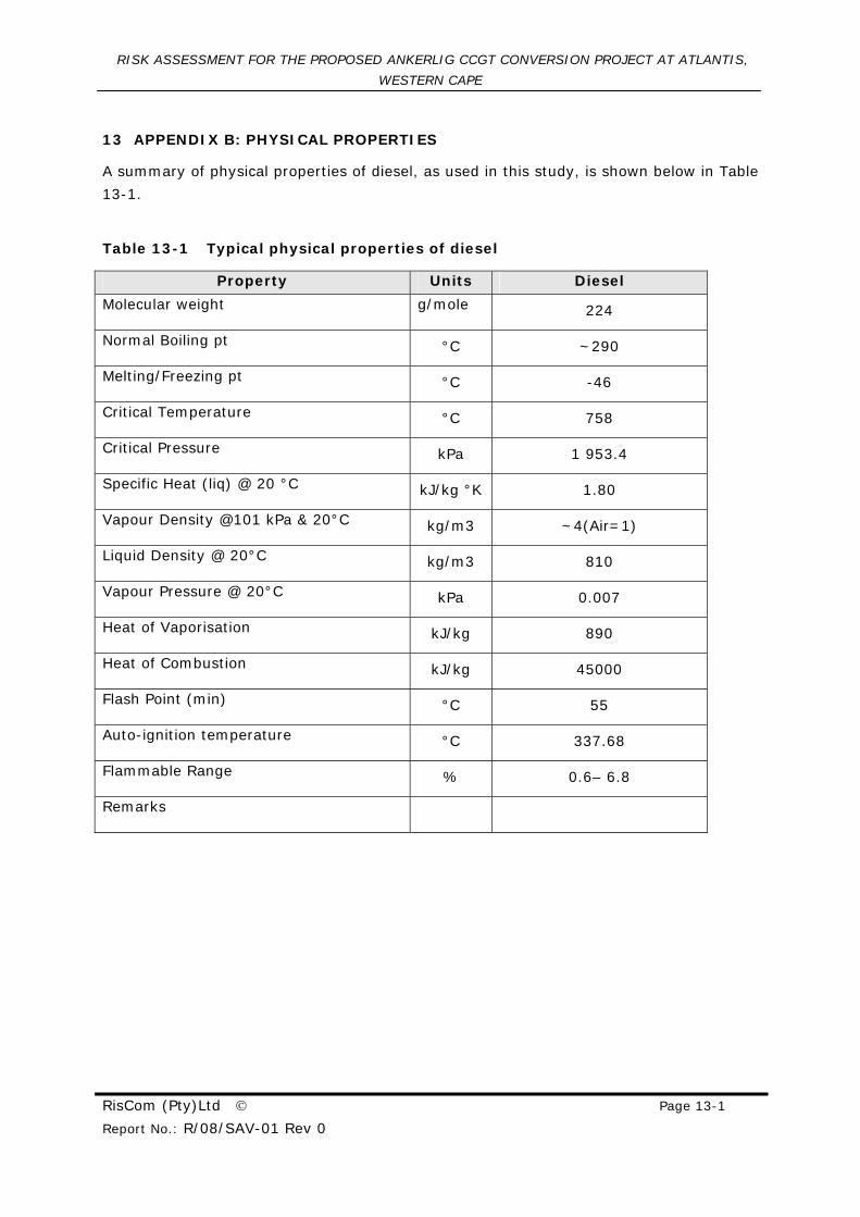
13 APPENDIX B: PHYSICAL PROPERTIES
A summary of physical properties of diesel, as used in this study, is shown below in Table
13-1.
Table 13-1 Typical physical properties of diesel
Property Units Diesel
Molecular weight g/mole 224
Normal Boiling pt °C ~290
Melting/Freezing pt °C -46
Critical Temperature °C 758
Critical Pressure kPa 1 953.4
Specific Heat (liq) @ 20 °C kJ/kg °K 1.80
Vapour Density @101 kPa & 20°C kg/m3 ~4(Air=1)
Liquid Density @ 20°C kg/m3 810
Vapour Pressure @ 20°C kPa 0.007
Heat of Vaporisation kJ/kg 890
Heat of Combustion kJ/kg 45000
Flash Point (min) °C 55
Auto-ignition temperature °C 337.68
Flammable Range % 0.6– 6.8
Remarks
RISK ASSESSMENT FOR THE PROPOSED ANKERLIG CCGT CONVERSION PROJECT AT ATLANTIS,
WESTERN CAPE
RisCom (Pty)Ltd © Page 13-2
Report No.: R/08/SAV-01 Rev 0
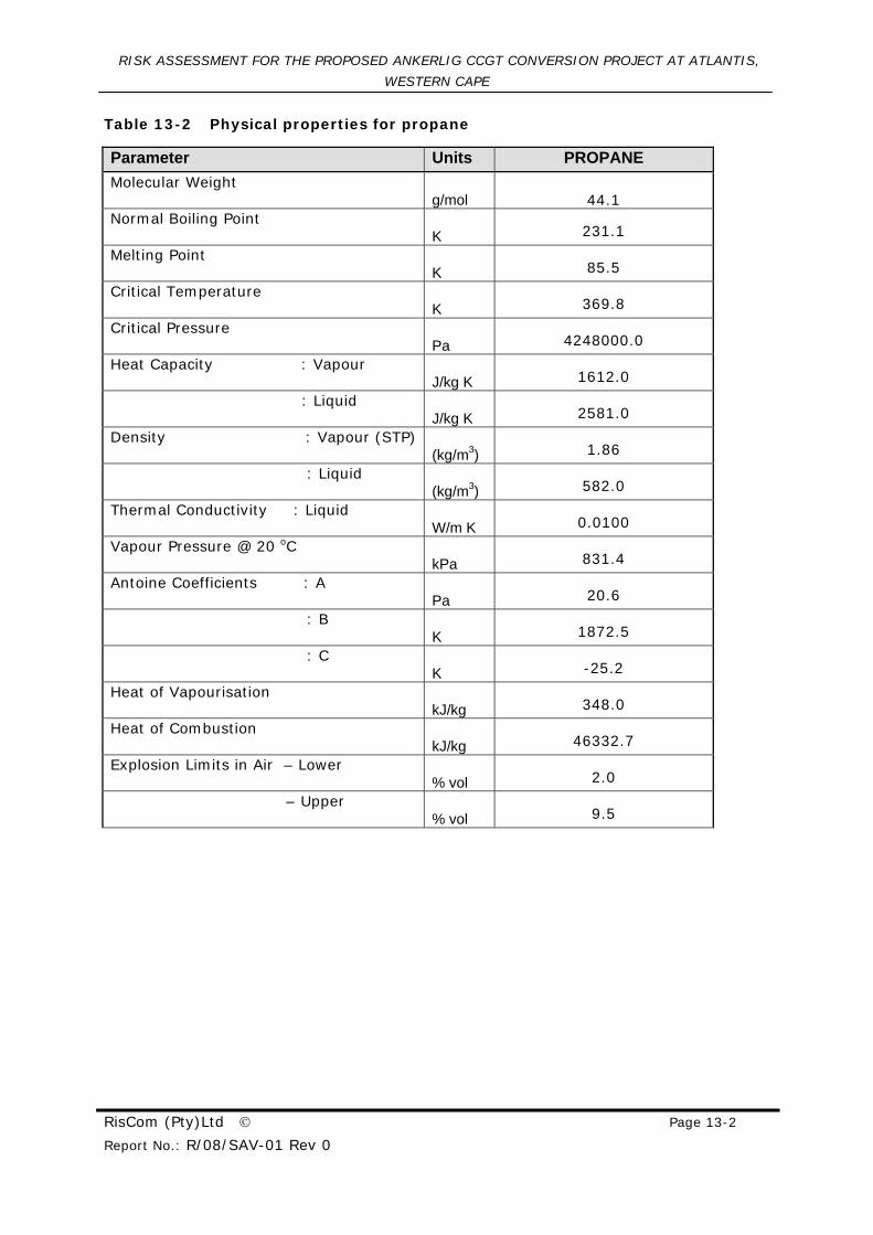
Table 13-2 Physical properties for propane
Parameter Units PROPANE Molecular Weight
g/mol 44.1 Normal Boiling Point
K 231.1
Melting Point K 85.5
Critical Temperature K 369.8
Critical Pressure Pa 4248000.0
Heat Capacity : Vapour J/kg K 1612.0
: Liquid J/kg K 2581.0
Density : Vapour (STP) (kg/m3) 1.86
: Liquid (kg/m3) 582.0
Thermal Conductivity : Liquid W/m K 0.0100
Vapour Pressure @ 20 oC kPa 831.4
Antoine Coefficients : A Pa 20.6
: B K 1872.5
: C K -25.2
Heat of Vapourisation kJ/kg 348.0
Heat of Combustion kJ/kg 46332.7
Explosion Limits in Air – Lower % vol 2.0
– Upper % vol 9.5
RISK ASSESSMENT FOR THE PROPOSED ANKERLIG CCGT CONVERSION PROJECT AT ATLANTIS, WESTERN CAPE
RisCom (Pty)Ltd © Page 14-1
Report No.: R/08/SAV-01 Rev 0
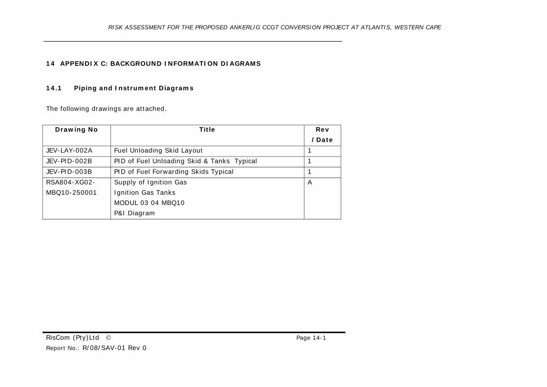
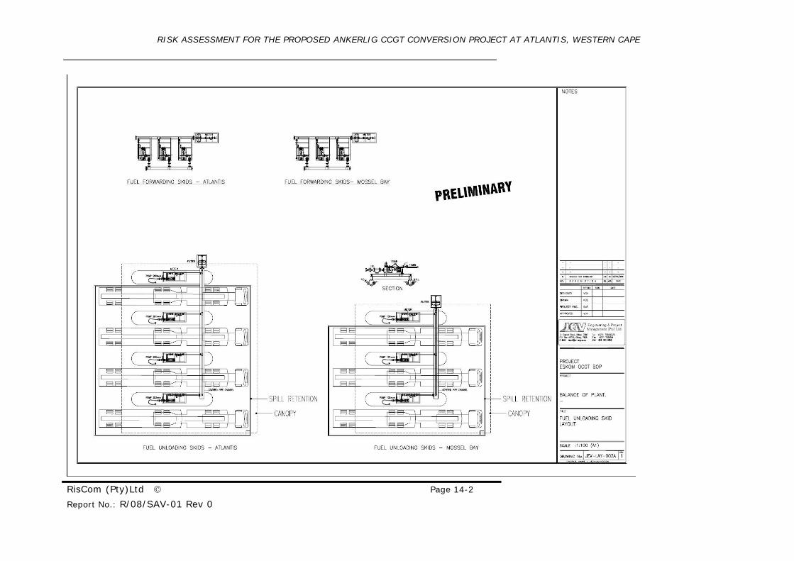
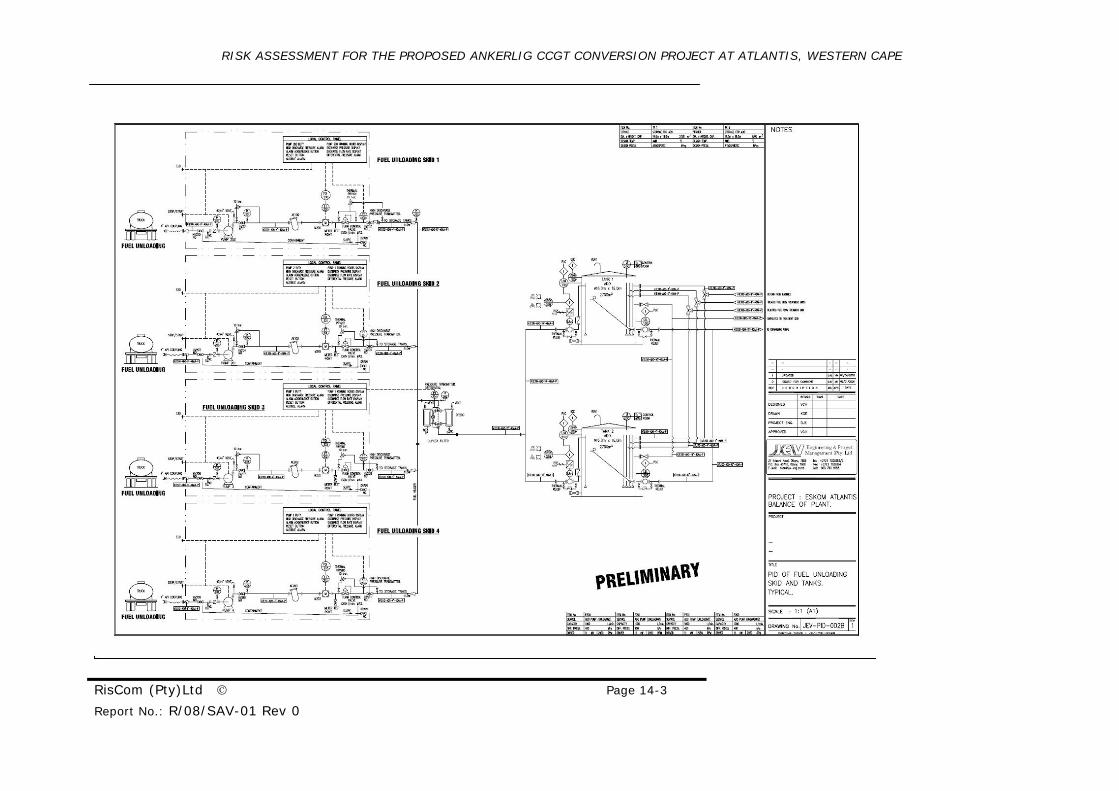
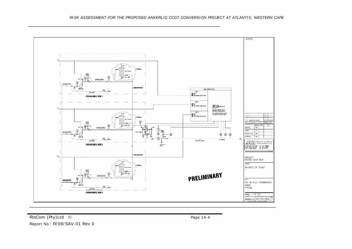
14 APPENDIX C: BACKGROUND INFORMATION DIAGRAMS
14.1 Piping and Instrument Diagrams
The following drawings are attached.
Drawing No Title Rev
/Date
JEV-LAY-002A Fuel Unloading Skid Layout 1
JEV-PID-002B PID of Fuel Unloading Skid & Tanks Typical 1
JEV-PID-003B PID of Fuel Forwarding Skids Typical 1
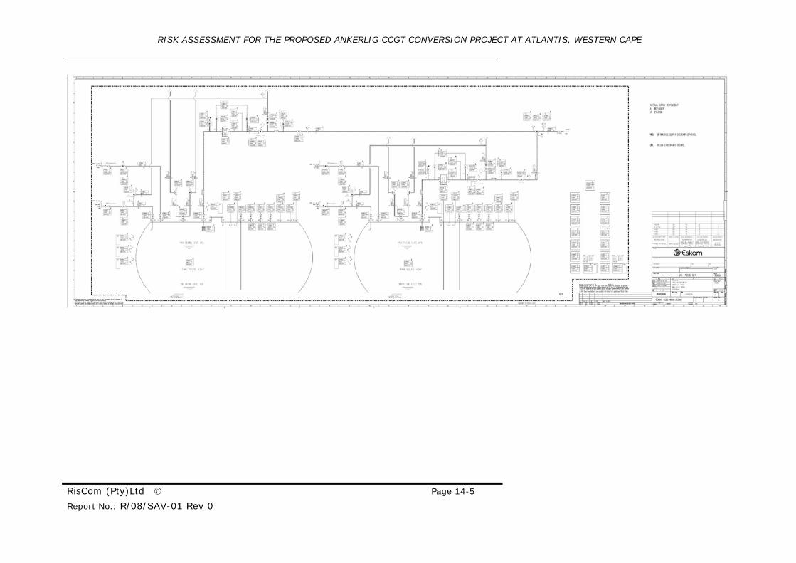
RSA804-XG02-
MBQ10-250001
Supply of Ignition Gas
Ignition Gas Tanks
MODUL 03 04 MBQ10
P&I Diagram
A
RISK ASSESSMENT FOR THE PROPOSED ANKERLIG CCGT CONVERSION PROJECT AT ATLANTIS, WESTERN CAPE
RisCom (Pty)Ltd © Page 14-2
Report No.: R/08/SAV-01 Rev 0
RISK ASSESSMENT FOR THE PROPOSED ANKERLIG CCGT CONVERSION PROJECT AT ATLANTIS, WESTERN CAPE
RisCom (Pty)Ltd © Page 14-3
Report No.: R/08/SAV-01 Rev 0
RISK ASSESSMENT FOR THE PROPOSED ANKERLIG CCGT CONVERSION PROJECT AT ATLANTIS, WESTERN CAPE
RisCom (Pty)Ltd © Page 14-4
Report No.: R/08/SAV-01 Rev 0
RISK ASSESSMENT FOR THE PROPOSED ANKERLIG CCGT CONVERSION PROJECT AT ATLANTIS, WESTERN CAPE
RisCom (Pty)Ltd © Page 14-5
Report No.: R/08/SAV-01 Rev 0
RISK ASSESSMENT FOR THE PROPOSED ANKERLIG CCGT CONVERSION PROJECT AT ATLANTIS,
WESTERN CAPE
RisCom (Pty)Ltd © Page 14-1
Report No.: R/08/SAV-01 Rev 0
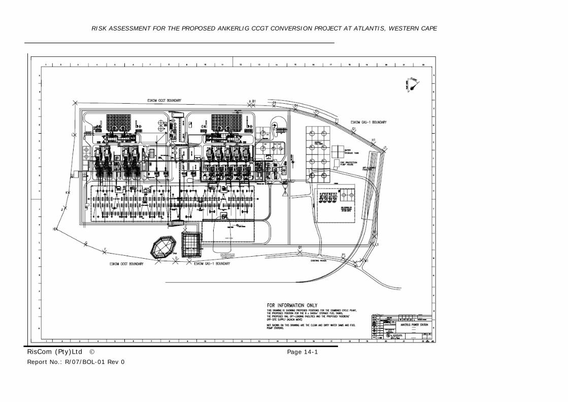
14.2 Plot Plan of the Ankerlig Power Station and CCGT Conversion Project
The following drawing is attached.
Drawing No Title Rev /Date
Unknown Ankerlig Power Station
Unknown
RISK ASSESSMENT FOR THE PROPOSED ANKERLIG CCGT CONVERSION PROJECT AT ATLANTIS, WESTERN CAPE
RisCom (Pty)Ltd © Page 14-1 Report No.: R/07/BOL-01 Rev 0
RISK ASSESSMENT FOR THE PROPOSED ANKERLIG CCGT CONVERSION PROJECT AT ATLANTIS,
WESTERN CAPE
RisCom (Pty)Ltd © Page 15-1 Report No.: R/07/BOL-01 Rev 0
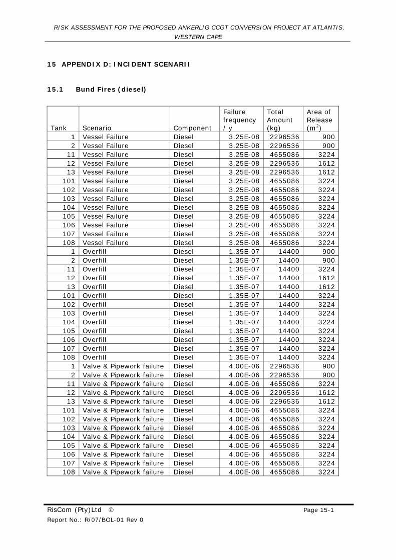
15 APPENDIX D: INCIDENT SCENARII
15.1 Bund Fires (diesel)
Tank Scenario Component
Failure frequency / y
Total Amount (kg)
Area of Release (m2)
1 Vessel Failure Diesel 3.25E-08 2296536 900 2 Vessel Failure Diesel 3.25E-08 2296536 900
11 Vessel Failure Diesel 3.25E-08 4655086 3224 12 Vessel Failure Diesel 3.25E-08 2296536 1612 13 Vessel Failure Diesel 3.25E-08 2296536 1612
101 Vessel Failure Diesel 3.25E-08 4655086 3224 102 Vessel Failure Diesel 3.25E-08 4655086 3224 103 Vessel Failure Diesel 3.25E-08 4655086 3224 104 Vessel Failure Diesel 3.25E-08 4655086 3224 105 Vessel Failure Diesel 3.25E-08 4655086 3224 106 Vessel Failure Diesel 3.25E-08 4655086 3224 107 Vessel Failure Diesel 3.25E-08 4655086 3224 108 Vessel Failure Diesel 3.25E-08 4655086 3224
1 Overfill Diesel 1.35E-07 14400 900 2 Overfill Diesel 1.35E-07 14400 900
11 Overfill Diesel 1.35E-07 14400 3224 12 Overfill Diesel 1.35E-07 14400 1612 13 Overfill Diesel 1.35E-07 14400 1612
101 Overfill Diesel 1.35E-07 14400 3224 102 Overfill Diesel 1.35E-07 14400 3224 103 Overfill Diesel 1.35E-07 14400 3224 104 Overfill Diesel 1.35E-07 14400 3224 105 Overfill Diesel 1.35E-07 14400 3224 106 Overfill Diesel 1.35E-07 14400 3224 107 Overfill Diesel 1.35E-07 14400 3224 108 Overfill Diesel 1.35E-07 14400 3224
1 Valve & Pipework failure Diesel 4.00E-06 2296536 900 2 Valve & Pipework failure Diesel 4.00E-06 2296536 900
11 Valve & Pipework failure Diesel 4.00E-06 4655086 3224 12 Valve & Pipework failure Diesel 4.00E-06 2296536 1612 13 Valve & Pipework failure Diesel 4.00E-06 2296536 1612
101 Valve & Pipework failure Diesel 4.00E-06 4655086 3224 102 Valve & Pipework failure Diesel 4.00E-06 4655086 3224 103 Valve & Pipework failure Diesel 4.00E-06 4655086 3224 104 Valve & Pipework failure Diesel 4.00E-06 4655086 3224 105 Valve & Pipework failure Diesel 4.00E-06 4655086 3224 106 Valve & Pipework failure Diesel 4.00E-06 4655086 3224 107 Valve & Pipework failure Diesel 4.00E-06 4655086 3224 108 Valve & Pipework failure Diesel 4.00E-06 4655086 3224
RISK ASSESSMENT FOR THE PROPOSED ANKERLIG CCGT CONVERSION PROJECT AT ATLANTIS, WESTERN CAPE
RisCom (Pty)Ltd © Page 15-1 Report No.: R/07/BOL-01 Rev 0
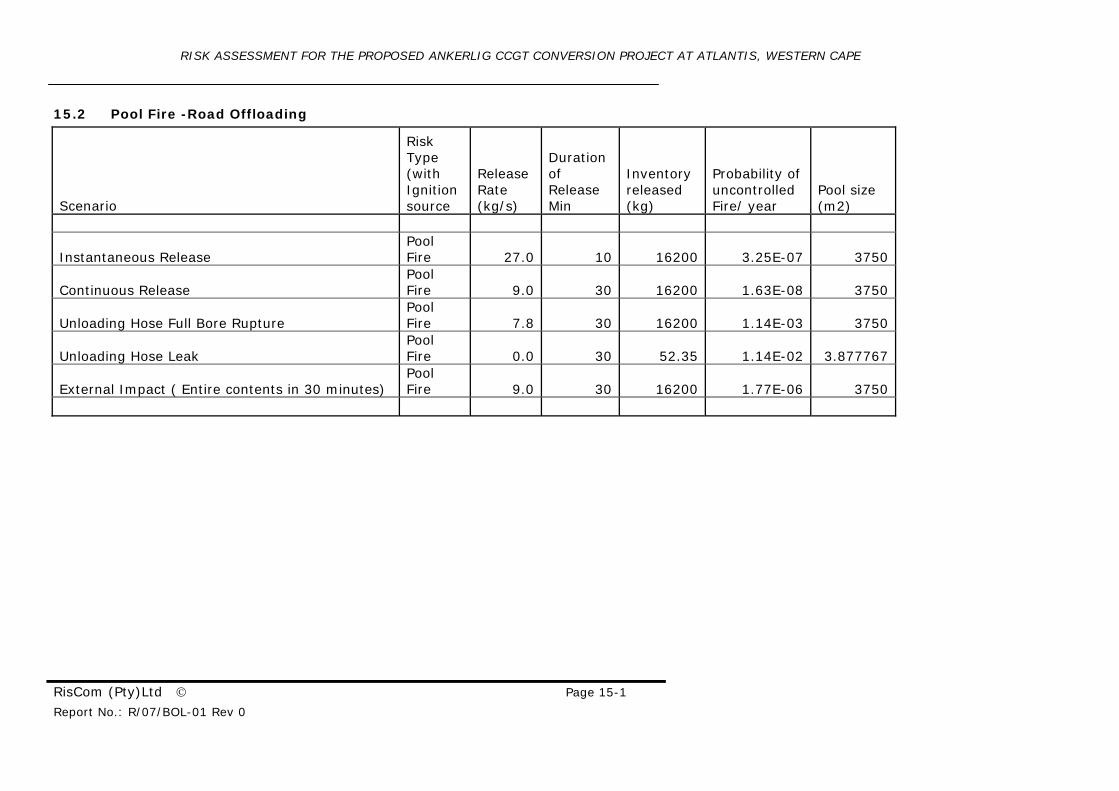
15.2 Pool Fire -Road Offloading
Scenario
Risk Type (with Ignition source
Release Rate (kg/s)
Duration of Release Min
Inventory released (kg)
Probability of uncontrolled Fire/ year
Pool size (m2)
Instantaneous Release Pool Fire 27.0 10 16200 3.25E-07 3750
Continuous Release Pool Fire 9.0 30 16200 1.63E-08 3750
Unloading Hose Full Bore Rupture Pool Fire 7.8 30 16200 1.14E-03 3750
Unloading Hose Leak Pool Fire 0.0 30 52.35 1.14E-02 3.877767
External Impact ( Entire contents in 30 minutes) Pool Fire 9.0 30 16200 1.77E-06 3750
RISK ASSESSMENT FOR THE PROPOSED ANKERLIG CCGT CONVERSION PROJECT AT ATLANTIS, WESTERN CAPE
RisCom (Pty)Ltd © Page 15-2 Report No.: R/07/BOL-01 Rev 0
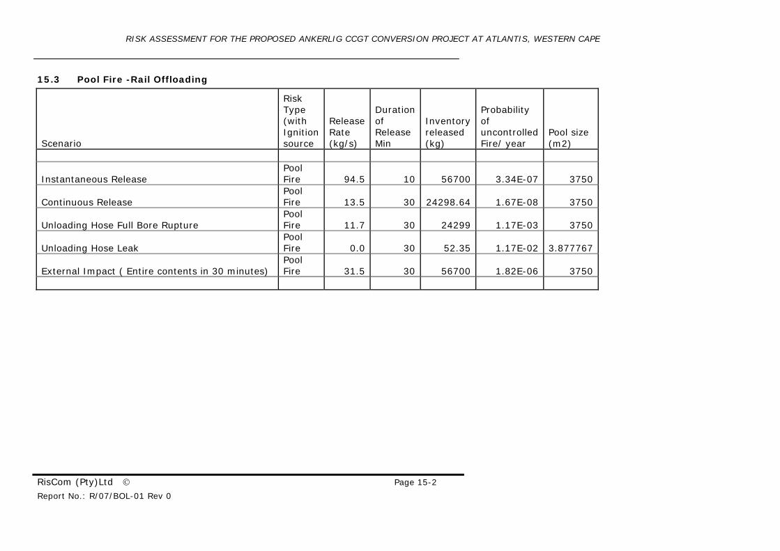
15.3 Pool Fire -Rail Offloading
Scenario
Risk Type (with Ignition source
Release Rate (kg/s)
Duration of Release Min
Inventory released (kg)
Probability of uncontrolled Fire/ year
Pool size (m2)
Instantaneous Release Pool Fire 94.5 10 56700 3.34E-07 3750
Continuous Release Pool Fire 13.5 30 24298.64 1.67E-08 3750
Unloading Hose Full Bore Rupture Pool Fire 11.7 30 24299 1.17E-03 3750
Unloading Hose Leak Pool Fire 0.0 30 52.35 1.17E-02 3.877767
External Impact ( Entire contents in 30 minutes) Pool Fire 31.5 30 56700 1.82E-06 3750
RISK ASSESSMENT FOR THE PROPOSED ANKERLIG CCGT CONVERSION PROJECT AT ATLANTIS, WESTERN CAPE
RisCom (Pty)Ltd © Page 15-3 Report No.: R/07/BOL-01 Rev 0
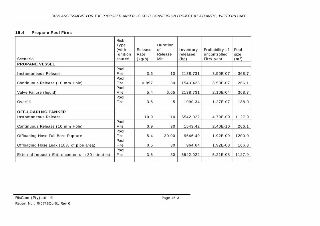
15.4 Propane Pool Fires
Scenario
Risk Type (with Ignition source
Release Rate (kg/s)
Duration of Release Min
Inventory released (kg)
Probability of uncontrolled Fire/ year
Pool size (m2)
PROPANE VESSEL
Instantaneous Release Pool Fire 3.6 10 2138.731 3.50E-07 368.7
Continuous Release (10 mm Hole) Pool Fire 0.857 30 1543.423 3.50E-07 266.1
Valve Failure (liquid) Pool Fire 5.4 6.65 2138.731 2.10E-04 368.7
Overfill Pool Fire 3.6 5 1090.34 1.27E-07 188.0
OFF-LOADING TANKER Instantaneous Release 10.9 10 6542.022 4.79E-09 1127.9
Continuous Release (10 mm Hole) Pool Fire 0.9 30 1543.42 2.40E-10 266.1
Offloading Hose Full Bore Rupture Pool Fire 5.4 30.00 9646.40 1.92E-09 1200.0
Offloading Hose Leak (10% of pipe area) Pool Fire 0.5 30 964.64 1.92E-08 166.3
External Impact ( Entire contents in 30 minutes) Pool Fire 3.6 30 6542.022 5.21E-08 1127.9