Embed Size (px)
Citation preview
Smart Card
REPO RT
Ankit Laddha
2009EE10276
iit delhi
Proposal
Introduction
I propose to build a money transaction module using a smart card with Radio Frequency Identification (RFID) technology. This identification module consistes of a RFID Card and Reader, a microcontroller and a server to store and process data.
This smart card will aid in easy money transaction in busy public transportation services like buses and trains and also makes transactions easier for sightseers in places of tourist attraction. Apart from these applications, the smart card has multifarious functionality, when combined with Global Positioning System and other upcoming technological innovations.
Motivation
Automation of services has been a constant endeavour of techonlogy. Cashless payment systems is one such endeavour which will greatly help reduce delays due to payments in crowded places.
This is helpful especially in densely populated areas like India. Our public transportation systems have a vast multitude of customers and we can use a Smart Card system to make the payment system fast, efficient and automatic. People can swipe a card to pay for bus and train fares without any hassles or the fear of money being stolen. Thus a cashless payment system will aid our public transportation sector in a huge way.
Design
Components
• RFID Reaeder • Microcontroller (ARDUINO ATmega 2560) • Server • LCD
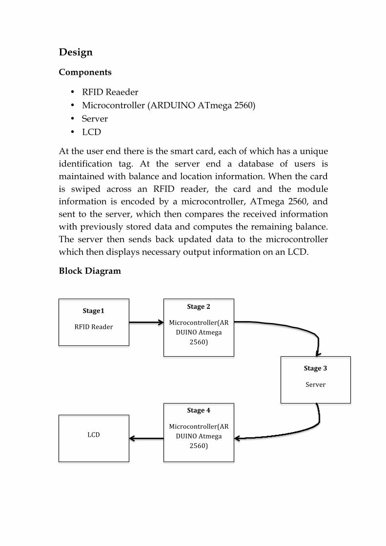
At the user end there is the smart card, each of which has a unique identification tag. At the server end a database of users is maintained with balance and location information. When the card is swiped across an RFID reader, the card and the module information is encoded by a microcontroller, ATmega 2560, and sent to the server, which then compares the received information with previously stored data and computes the remaining balance. The server then sends back updated data to the microcontroller which then displays necessary output information on an LCD.
Block Diagram
Stage1
RFID Reader
Stage 2
Microcontroller(ARDUINO Atmega
2560)
Stage 3
Server
LCD
Stage 4
Microcontroller(ARDUINO Atmega
2560)
Description of each stage of the block diagram
1. RFID Reader
RFID (Radio Frequency Identification) is one member in the family of Automatic Identification and Data Capture (AIDC) technologies and is a fast and reliable means of identifying objects. There are two main components:
1. The Interrogator (RFID Reader), which transmits and receives the signal and the Transponder (tag) that is attached to the object.
2. An RFID tag is composed of a miniscule microchip and antenna. RFID tags can be passive or active and come in a wide variety of sizes, shapes, and forms.
Types of RFID tags Passive tags: These transponders are only activated when within the response range of an RFID Reader. Active tags: These incorporate their own power source. The tag is a transmitter rather than a reflector of radio frequency signals which enables a broader range of functionality like programmable and read/write capabilities. Functioning Communication between the RFID Reader and tags occurs wirelessly. The RFID Reader emits a low-power radio wave field which is used to power up the tag so as to pass on any information that is contained on the chip. The frequencies used cover a wide spectrum.
1. Very long wave 9 - 135 kHz 2. Short wave 13.56 MHz 3. UHF 400-1200 MHz 4. Microwave 2.45 and 5.8 GHz
The allocation of frequencies is regulated by government agencies. High-frequency systems offer long reading ranges and high reading speeds but at higher costs. Environmental conditions, particularly at the higher frequencies, can also influence the range of communication.
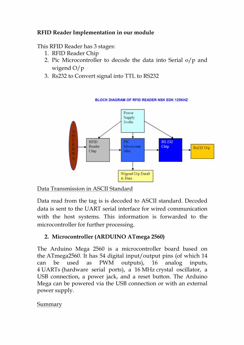
RFID Reader Implementation in our module This RFID Reader has 3 stages:
1. RFID Reader Chip 2. Pic Microcontroller to decode the data into Serial o/p and
wigend O/p 3. Rs232 to Convert signal into TTL to RS232
Data Transmission in ASCII Standard
Data read from the tag is is decoded to ASCII standard. Decoded data is sent to the UART serial interface for wired communication with the host systems. This information is forwarded to the microcontroller for further processing.
2. Microcontroller (ARDUINO ATmega 2560)
The Arduino Mega 2560 is a microcontroller board based on the ATmega2560. It has 54 digital input/output pins (of which 14 can be used as PWM outputs), 16 analog inputs, 4 UARTs (hardware serial ports), a 16 MHz crystal oscillator, a USB connection, a power jack, and a reset button. The Arduino Mega can be powered via the USB connection or with an external power supply. Summary
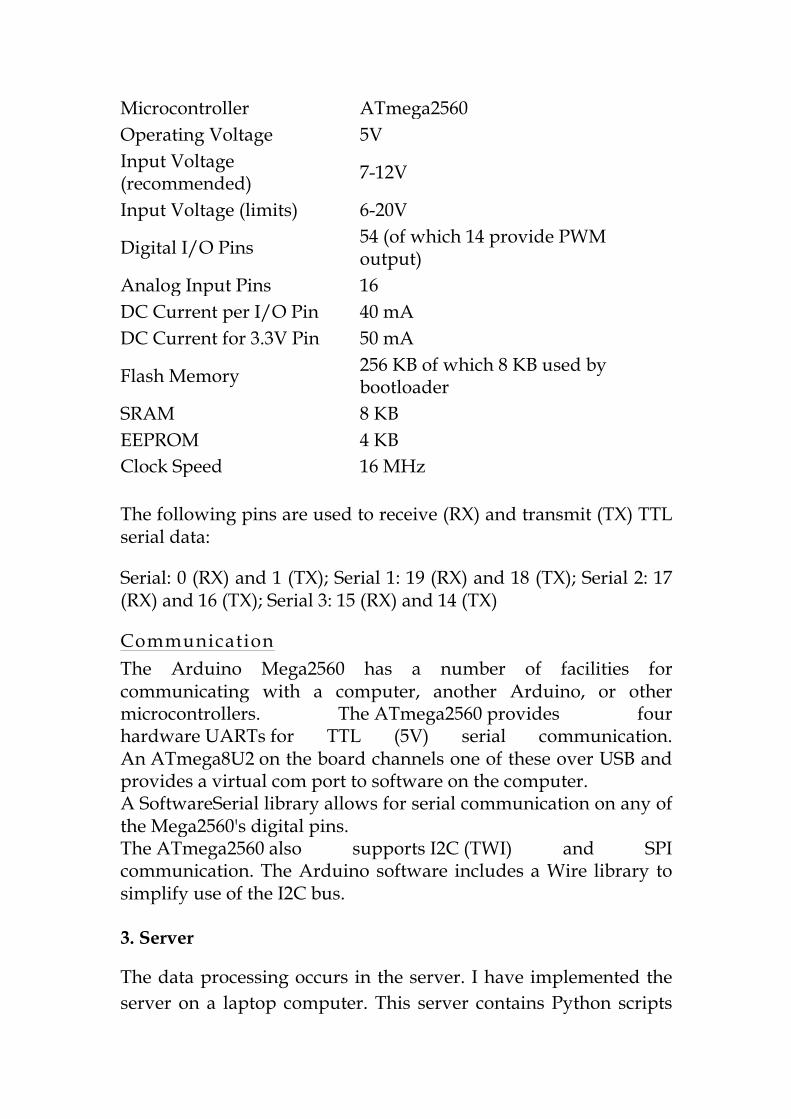
Microcontroller ATmega2560 Operating Voltage 5V Input Voltage (recommended) 7-12V
Input Voltage (limits) 6-20V
Digital I/O Pins 54 (of which 14 provide PWM output)
Analog Input Pins 16 DC Current per I/O Pin 40 mA DC Current for 3.3V Pin 50 mA
Flash Memory 256 KB of which 8 KB used by bootloader
SRAM 8 KB EEPROM 4 KB Clock Speed 16 MHz The following pins are used to receive (RX) and transmit (TX) TTL serial data:
Serial: 0 (RX) and 1 (TX); Serial 1: 19 (RX) and 18 (TX); Serial 2: 17 (RX) and 16 (TX); Serial 3: 15 (RX) and 14 (TX)
Communication The Arduino Mega2560 has a number of facilities for communicating with a computer, another Arduino, or other microcontrollers. The ATmega2560 provides four hardware UARTs for TTL (5V) serial communication. An ATmega8U2 on the board channels one of these over USB and provides a virtual com port to software on the computer. A SoftwareSerial library allows for serial communication on any of the Mega2560's digital pins. The ATmega2560 also supports I2C (TWI) and SPI communication. The Arduino software includes a Wire library to simplify use of the I2C bus. 3. Server
The data processing occurs in the server. I have implemented the server on a laptop computer. This server contains Python scripts
that are used to interpret the data and commands sent by the microcontroller. The server waits for the microcontroller to send instructions.
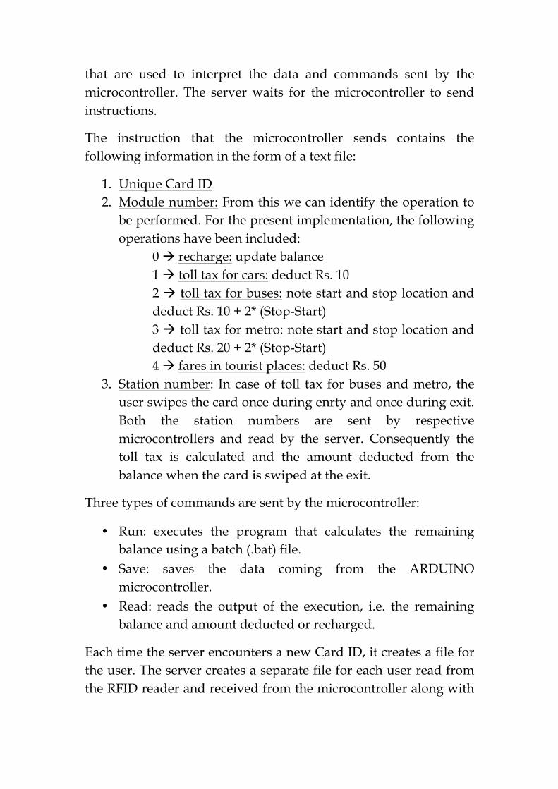
The instruction that the microcontroller sends contains the following information in the form of a text file:
1. Unique Card ID 2. Module number: From this we can identify the operation to
be performed. For the present implementation, the following operations have been included:
0 à recharge: update balance 1 à toll tax for cars: deduct Rs. 10 2 à toll tax for buses: note start and stop location and deduct Rs. 10 + 2* (Stop-Start) 3 à toll tax for metro: note start and stop location and deduct Rs. 20 + 2* (Stop-Start) 4 à fares in tourist places: deduct Rs. 50
3. Station number: In case of toll tax for buses and metro, the user swipes the card once during enrty and once during exit. Both the station numbers are sent by respective microcontrollers and read by the server. Consequently the toll tax is calculated and the amount deducted from the balance when the card is swiped at the exit.
Three types of commands are sent by the microcontroller:
• Run: executes the program that calculates the remaining balance using a batch (.bat) file.
• Save: saves the data coming from the ARDUINO microcontroller.
• Read: reads the output of the execution, i.e. the remaining balance and amount deducted or recharged.
Each time the server encounters a new Card ID, it creates a file for the user. The server creates a separate file for each user read from the RFID reader and received from the microcontroller along with
balance information. All transaction is updated into the server after necessary deductions have been made by the JAVA code.
4. LCD
The server then sends back the updated balance information to the microcontroller which then displays this information on LCD.
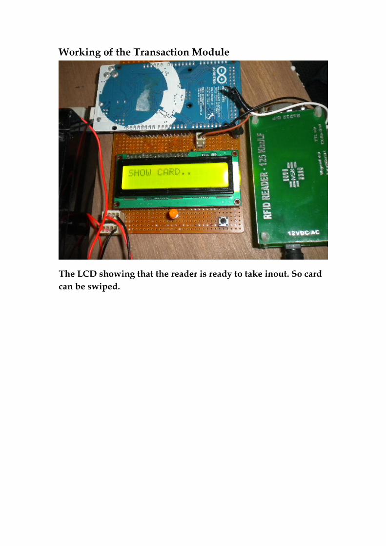
Working of the Transaction Module
The LCD showing that the reader is ready to take inout. So card can be swiped.
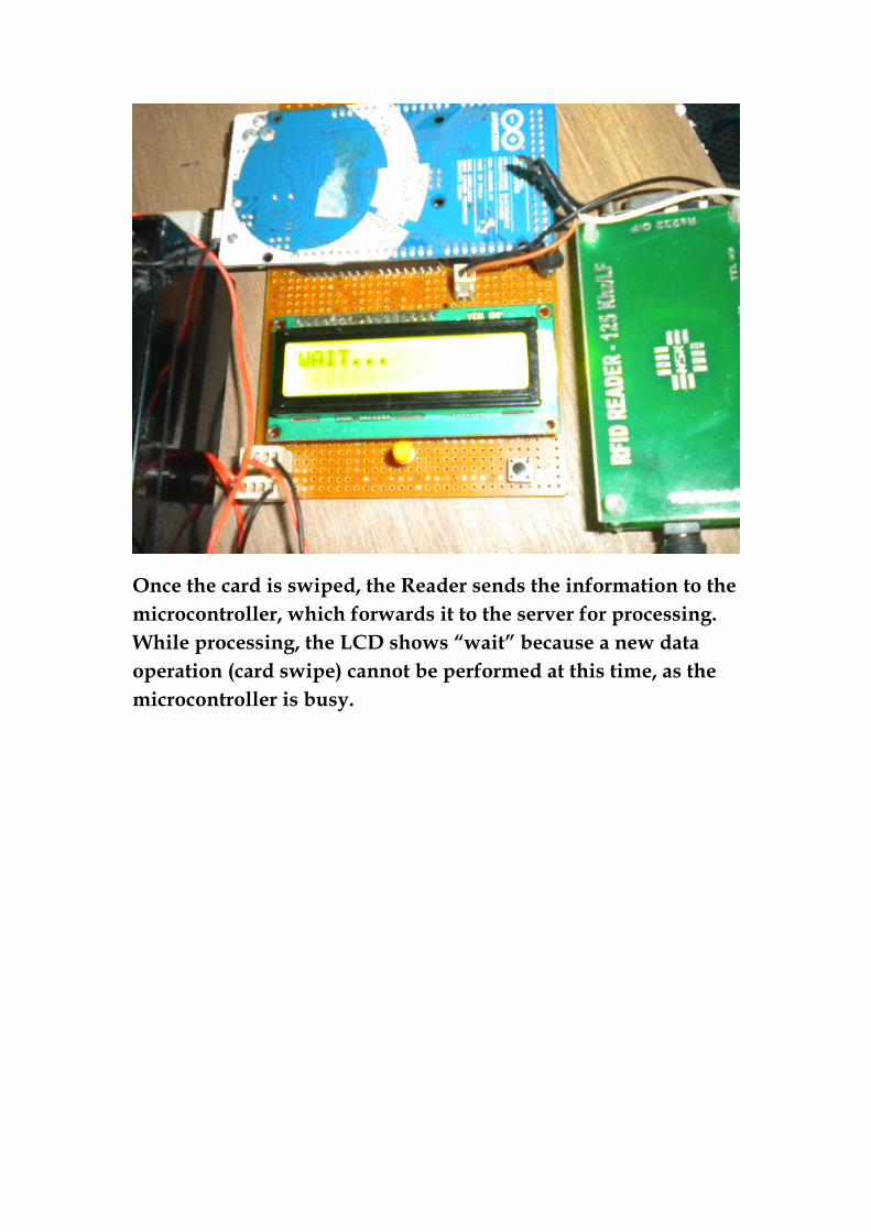
Once the card is swiped, the Reader sends the information to the microcontroller, which forwards it to the server for processing. While processing, the LCD shows “wait” because a new data operation (card swipe) cannot be performed at this time, as the microcontroller is busy.
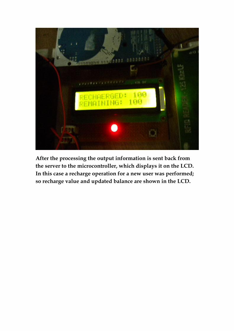
After the processing the output information is sent back from the server to the microcontroller, which displays it on the LCD. In this case a recharge operation for a new user was performed; so recharge value and updated balance are shown in the LCD.
Applications
1. This Smart Card can be effectively used to implement Cash less payment systems local to campuses and institutions:
• In IIT, we have a coupon-based system for extra-messing services. This can replaced by the Smart card efficiently which will make the transaction process easier and centralized.
• A centralized database can be maintained for shops and make transactions easier through the Smart Card.
• If the Smart Card is implemented into the student ID Cards, it can be used for a wide range of academic functions, like attendance.
2. If integtrated with GPS, we can fix modules in buses and trains. When the traveller enters the train and swipes his card the location is noted and the same is done when he exits the vehicle. The distance is then measured from his coordinates and the fare amount is calculated and deducted. Such an automatic payment system can be implemented easily and efficiently.
3. The Smart Card can be used for fare deduction in tourist places. A module can be placed in the gateways of monuments and places which will deduct a fixed amount of money from the subscriber’s card and allow entry. Thus tourists can be provied with cards in the Airport and other places which will make money transactions easier for tourists, especially foreign tourists.