Embed Size (px)
Citation preview
Annals of DAAAM for 2012 & Proceedings of the 23rd International DAAAM Symposium, Volume 23, No.1, ISSN 2304-1382
ISBN 978-3-901509-91-9, CDROM version, Ed. B. Katalinic, Published by DAAAM International, Vienna, Austria, EU, 2012
Make Harmony between Technology and Nature, and Your Mind will Fly Free as a Bird
Annals & Proceedings of DAAAM International 2012
FLANK WEAR IN DOWN AND UP MILLING
JOZIC, S[onja]; BAJIC, D[razen] & TOPIC, S[andra]
Abstract: This study is carried out to observe the flank wear in
up and down milling in the case of peripheral milling.
Equations for flank wear have been obtained by means of
design of experiments and regression analysis. This research
has shown that the time of inserts engagement has the largest
influence on flank wear and the radial depth of cut the least in
down milling. In up milling time of inserts engagement and
cutting speed have the approximatly equal influence.
Hereinafter, flank wear correlated with the volume of the
removed material for different processing parameters has been
analysed. Observed from the viewpoint of removed material
and flank wear, down milling is favorable compared to the up
milling.
Keywords: flank wear, design of experiments, regression
analysis, material removal rate
1. INTRODUCTION In manufacturing industries milling is generally used
to produce parts which are not axially symmetric and have many features such as holes, slots, pockets and three dimensional surfaces contours. This process is capable of producing machine elements with complex shapes and high surface quality, such as molds and dies, gears, shafts, blades etc. The productivity of machining processes, as well as the integrity of the machined surface are strongly related to the tool wear and tool life. Tool wear, hence becomes the key factor in the machining processes. If a worn tool is not identified beforehand, significant degradation of the workpiece quality can occur. Therefore, research in this area is still of great significance.
This study proposes the application of the design of experiments (DOE) methodology to the prediction of flank wear (VB) in the milling process of 42CrMo4 steel. Cutting speed (vc), feed per tooth (ft), radial depth of cut (ae) and time of inserts engagement (t) were employed as input variable. In milling, time of inserts engagement is not the same as the machining time and depends on the mill diameter and radial depth of cut. The paper separately observed down and up milling in the case of peripheral milling.
The main goal of this research is directed toward to examining the influence of cutting parameters and time of inserts engagement, as well as the direction of milling on the tool wear, particulary on the flank wear.
2. LITERATURE REVIEW Many mathematical models have been developed to
describe tool wear in quantitative terms. Researchers have attempted to directly correlate the amount of tool wear and tool life to the applied machining parameters, machining time, workpiece and tool materials, etc.
Kwon and Fisher [1] have developed the tool wear index (TWI) and the tool life model, analyzing the wear surface areas and the tool material loss using micro-optics, image processing and an analysis algorithm. With relation to surface roughness, the TWI measures the minimum risk for in-process tool failure. This criterion is integrated in an optimal control strategy according to productivity improvement and reduction of costs of manufacturing. Özel, Karpat, Figueira & Davim [2] have investigated the influence of cutting parameters on the tool flank wear and surface roughness in finish turning of hard steel. Similar modeling methodology and measuring techniques have been performed by Lajis, Mustafizul Karim, Nurul Amin, Hafiz, & Turnad [3] in end milling of hardened steel. Nouari & Molinari [4] have investigated uncoated tool wear during machining of low-alloyed steel (DIN: 42CrMo4, AISI: 4140). The tool wear in orthogonal cutting has been estimated by Yen, Soehner, Lilly & Altan, [5]. Based on temperatures and stresses on the tool face predicted by the finite element analysis (FEA) simulation, they estimate the tool wear with accepTab. accuracy using an empirical wear model.
3. TOOL WEAR The cutting tool in any machining process is
subjected to changes of its geometry and changes of respective material properties. Tribological processes leading to tool wear occur at rake and flank face, Fig. 1
Fig. 1.Form of tool wear, [6]
- 0251 -
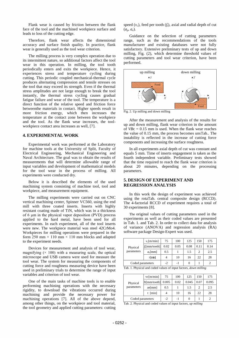
Flank wear is caused by friction between the flank face of the tool and the machined workpiece surface and leads to loss of the cutting edge.
Therefore, flank wear affects the dimensional accuracy and surface finish quality. In practice, flank wear is generally used as the tool wear criterion.
The milling process is very complex operation due to its intermittent nature, so additional factors affect the tool wear in this operation. In milling, the tool tooth periodically enters and exits the workpiece. Hence, it experiences stress and temperature cycling during cutting. This periodic coupled mechanical-thermal cycle produces alternating compression and tensile stresses on the tool that may exceed its strength. Even if the thermal stress amplitudes are not large enough to break the tool instantly, the thermal stress cycling causes gradual fatigue failure and wear of the tool. The temperature is a direct function of the relative speed and friction force betweenthe materials in contact. Higher speeds result in more friction energy, which then increases the temperature at the contact zone between the workpiece and the tool. As the flank wear increases, the tool-workpiece contact area increases as well, [7].
4. EXPERIMENTAL WORK Experimental work was performed at the Laboratory
for machine tools at the University of Split, Faculty of Electrical Engineering, Mechanical Engineering and Naval Architecture. The goal was to obtain the results of measurements that will determine allowable range of input variables and development of mathematical models for the tool wear in the process of milling. All experiments were conducted dry.
Below it is described the elements of the used machining system consisting of machine tool, tool and workpiece, and measurement equipment.
The milling experiments were carried out on CNC vertical machining center, Spinner VC560, using the end mill with three coated inserts. Inserts with highly resistant coating made of TiN, which was in a thickness of 6 µm in the physical vapor deposition (PVD) process applied to the hard metal, have been used for all experiments. In each experiment, all of the tool inserts were new. The workpiece material was steel 42CrMo4. Workpieces for milling operations were prepared in the form 250 mm × 110 mm × 110 mm blocks and adapted to the experiment needs.
Devices for measurement and analysis of tool wear, magnifying (× 100) with a measuring scale, the optical microscope and USB camera were used for measure the tool wear. The system for measuring the components of cutting force and roughness measuring device have been used in preliminary trials to determine the range of input variables and criterion of tool wear.
One of the main tasks of machine tools is to enable performing machining operations with the necessary rigidity, to download the vibrations occurred during machining and provide the necessary power for machining operations [7]. All of the above depend, among other things, on the workpiece and tool material, the tool geometry and applied cutting parameters: cutting
speed (vc), feed per tooth (ft), axial and radial depth of cut (ap, ae).
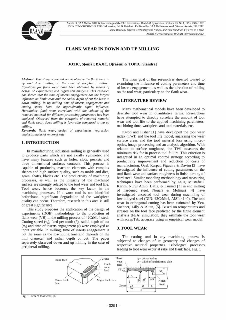
Guidance on the selection of cutting parameters range, such as the recommendations of the tools manufacturer and existing databases were not fully satisfactory. Extensive preliminary tests of up and down milling, Fig. (2), which determine threshold values of cutting parameters and tool wear criterion, have been
performed.
up milling down milling
Fig. 2. Up milling and down milling
After the measurement and analysis of the results for
up and down milling, flank wear criterion in the amount of VBc = 0.15 mm is used. When the flank wear reaches the value of 0.15 mm, the process becomes unsTab.. The instability is reflected in the increase of cutting force components and increasing the surface roughness.
In all experiments axial depth of cut was constant and equals 5 mm. Time of inserts engagement is taken as the fourth independent variable. Preliminary tests showed that the time required to reach the flank wear criterion is about 20 minutes, depending on the processing parameters.
5. DESIGN OF EXPERIMENT AND
REGRESSION ANALYSIS In this work the design of experiment was achieved
using the rotaTab. central composite design (RCCD). The 4-factorial RCCD of experiment requires a total of 30 experiments [8].
The original values of cutting parameters used in the experiments as well as their coded values are presented in Tab. 1. and Tab. 2. In order to collect data for analysis of variance (ANOVA) and regression analysis (RA) software package Design-Expert was used.
Physical
parameters
vc[m/min] 75 100 125 150 175
ft[mm/tooth] 0.02 0.05 0.08 0.11 0.14
ae[mm] 0.5 1 1.5 2 2.5
t [min] 4 10 16 22 28
Coded parameters -2 -1 0 1 2
Tab. 1. Physical and coded values of input factors, down milling
Physical
parameters
vc[m/min] 75 100 125 150 175
ft[mm/tooth] 0.005 0.02 0.045 0.07 0.095
ae[mm] 0.5 1 1.5 2 2.5
t [min] 4 10 16 22 28
Coded parameters -2 -1 0 1 2
Tab. 2. Physical and coded values of input factors, up milling
- 0252 -
Applying RA on the experimentally determined data the regression coefficients were obtained and thereby the regression equations for the flank wear too. After omitting the insignificant factors, the equations are defined as:
-Flank wear VB [mm] for down milling:
𝑉𝐵 = 0.01398− 0.00195𝑣𝑐 − 0.12021𝑓𝑡 + 0.01168𝑡 + + 0.000012𝑣𝑐
2 + 0.0282𝑎𝑒2 + 0.00575𝑣𝑐𝑓𝑡 −
−0.00071𝑣𝑐𝑎𝑒 − 0.023264𝑓𝑡𝑡 (1)
-Flank wear VB [mm] for up milling:
𝑉𝐵 = 0.02259 + 0.00038𝑣𝑐 − 0.00875𝑡 − 12.31667𝑓𝑡2 +
+0.000068𝑣𝑐𝑡 (2)
6. ANALYSIS OF RESULTS AND
DISCUSSION
After the validation of the models, a simulation of the
predictionwas performed. The simulation was carried out
by varying two input variables while the other two are
kept constant. The results obtained in that way are given,
partly, in a graphical form in Fig. 3 and Fig. 4. [9].
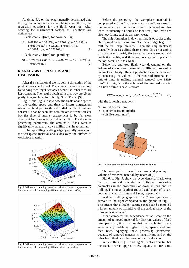
Fig. 3. and Fig. 4. show how the flank wear depends
on the cutting speed and time of inserts engagement
when the feed per tooth and radial depth of cut are
constant. It can be seen that both factors influence on VB,
but the time of inserts engagement is by far more
dominant factor especially in down milling. For the same
processing parameters, the amount of flank wear is
significantly smaller in down milling than in up milling.
In the up milling, cutting edge gradually enters into
the workpiece material and slides over the surface of
workpiece material.
Fig. 3. Influence of cutting speed and time of insert engagement on flank wear, ae = 1,5 mm and ft= 0,05 mm/tooth, down milling
Fig. 4. Influence of cutting speed and time of insert engagement on
flank wear, ae = 1,5 mm and ft= 0,05 mm/tooth, up milling
Before the removing, the workpiece material is
compressed and the first cracks occur as well. As a result,
the temperature in the cutting zone is increased and this
leads to intensify all forms of tool wear, and there are
also new forms, such as diffusion wear.
The chip formation in down milling is opposite to the
chip formation in up milling. The cutter edge begins to
mill the full chip thickness. Then the chip thickness
gradually decreases. Since there is no sliding or upsetting
of workpiece material, the treated surface is smooth and
has better quality, and there are no negative impacts on
the tool wear, i.e. flank wear.
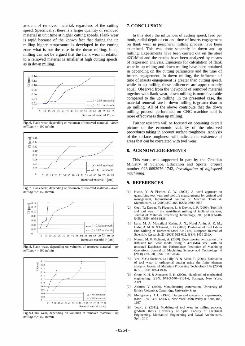
Below are analyzed flank wear depending on the
volume of the removed material for different processing
parameters. Highly efficient production can be achieved
by increasing the volume of the removed material in a
unit of time. In milling, material removal rate, MRR
[cm3/min], Fig. 5, or the volume of the removed material
in a unit of time is calculated as:
𝑀𝑅𝑅 = 𝑎𝑝𝑎𝑒𝑣𝑓 = 𝑎𝑝𝑎𝑒𝑓𝑡𝑛𝑁 = 𝑎𝑝𝑎𝑒𝑓𝑡𝑣𝑐1000
𝐷𝜋𝑁 (3)
with the following notations:
D – mill diameter, mm,
N – number of inserts (tooth),
n – spindle speed, min-1
.
Fig. 5. Parameters for determining of the MRR in milling
The wear profiles have been created depending on
volume of removed material, by means of (3).
Fig. 6. to Fig. 9. show the dependence of flank wear
on the removed material at different processing
parameters in the procedures of down milling and up
milling. The radial depth of cut and axial depth of cut are
constant and equal 1 mm and 5 mm, respectively.
In down milling, graphs in Fig. 7. are significantly
skewed to the right compared to the graphs in Fig. 6.
This means that at higher cutting speeds can be removed
a larger amount of material until the critical value of the
flank wear is achieved.
If one compares the dependence of tool wear on the
amount of removed material for different values of feed
rates per tooth, it is obvious that the machining is not
economically viable at higher cutting speeds and low
feed rates. Applying these processing parameters,
quantity of removed material is insignificant, and on the
other hand flank wear has reached a critical value.
In up milling, Fig. 8. and Fig. 9., is characteristic that
the flank wear is approximately equally for the same
110
115120
125130
135140
1012
1416
1820
220.05
0.09
0.13
0.17
0.21
0.25
vc [m/min]t [min]
VB
[m
m]
110115
120125
130135
140
1012
1416
1820
220.03
0.05
0.07
0.09
0.11
0.13
vc [m/min]t [min]
VB
[m
m]
- 0253 -
amount of removed material, regardless of the cutting
speed. Specifically, there is a larger quantity of removed
material in unit time at higher cutting speeds. Flank wear
is rapid because of the known fact that during the up
milling higher temperature is developed in the cutting
zone what is not the case in the down milling. In up
milling can not be argued that the flank wear in relation
to a removed material is smaller at high cutting speeds,
as in down milling.
Fig. 6. Flank wear, depending on volumen of removed material – down
milling, vc= 100 m/min
Fig. 7. Flank wear, depending on volumen of removed material – down
milling, vc= 150 m/min
Fig. 8. Flank wear, depending on volumen of removed material – up
milling, vc= 100 m/min
Fig. 9.Flank wear, depending on volumen of removed material – up
milling, vc= 150 m/min
7. CONCLUSION
In this study the influences of cutting speed, feed per tooth, radial depth of cut and time of inserts engagement on flank wear in peripheral milling process have been examined. This was done separatly in down and up milling. Experiments have been carried out on the steel 42CrMo4 and the results have been analyzed by means of regression analysis. Equations for calculation of flank wear in up miling and down milling have been obtained in depending on the cutting parameters and the time of inserts engagement. In down milling, the influence of time of inserts engagement is greater than cutting speed, while in up milling these influences are approximately equal. Observed from the viewpoint of removed material together with flank wear, down milling is more favorable compared to the up milling. In the presented case, the material removal rate in down milling is greater than in up milling. All of the above contribute that the down milling process perforemed on CNC machine tool is more effectivness than up milling.
Further research will be focused on obtaining overall picture of the economic viability of the observed procedures taking in account surface roughness. Analysis of the surface roughness will indicate the existence of areas that can be correlated with tool wear.
8. ACKNOWLEDGEMENTS This work was supported in part by the Croatian
Ministry of Science, Education and Sports, project number 023-0692976-1742, Investigation of highspeed machining.
9. REFERENCES
[1] Kwon, Y. & Fischer, G. W. (2003). A novel approach to quantifying tool wear and tool life measurements for optimal tool management, International Journal of Machine Tools & Manufacture, 43 (2003) 359-368, ISSN: 0890-6955
[2] Özel, T.; Karpat, Y; Figueira, L. & Davim, J. P. (2009). Tool life and tool wear in the semi-finish milling of inclined surfaces, Journal of Materials Processing Technology, 209 (2009) 5448-5455, ISSN: 0924-0136
[3] Lajis, M. A; Mustafizul Karim, A. N.; Nurul Amin, A. K. M.; Hafiz, A. M. K. &Turnad, L. G, (2008). Prediction of Tool Life in End Milling of Hardened Steel AISI D2, European Journal of Scientific Research, 21 (2008) 592-602, ISSN: 1450-216X
[4] Nouari, M. & Molinari, A. (2000). Experimental verification of a diffusion tool wear model using a 42CrMo4 steel with an uncoated Databases for Performance Prediction of Machining Operations, Journal of Machining Science and Technology, 4 (2000) 479-510, ISSN: 1091-0344
[5] Yen, Y-C.; Soehner, J.; Lilly, B. & Altan, T. (2004). Estimation of tool wear in orthogonal cutting using the finite element analysis, Journal of Materials Processing Technology 146 (2004) 82-91, ISSN: 0924-0136
[6] Grote, K. H. & Atonsons, E. K. (2009). Handbook of mechanical engineering, ISBN: 978-3-540-49131-6, Springer, New York, 2009
[7] Altintas, Y. (2000). Manufacturing Automation, University of British Columbia, Cambridge, University Press,
[8] Montgomery D. C. (1997). Design and analysis of experiments, ISBN: 978-0-470-12866-4, New York: John Wiley & Sons, Inc., 1997
[9] Topić, S. (2011). Modeling of tool wear in milling process, graduate thesis, University of Split, Faculty of Electrical Engineering, Mechanical Engineering and Naval Architecture, Split, 2011
- 0254 -