Embed Size (px)
Citation preview

Annex 6:
Navigation Assessment Report
March-2011
Proposed Xayaburi Dam Project
Assessment of the developer’s documents on the
planning, design, operations and management of
the navigation locks
March 2011
Prepared for the
Mekong River Commission Secretariat
By
Compagnie Nationale du Rhône
MRC Navigation Programme Office

Annex 6 of the Prior Consultation Project Review Report – Navigation Assessment Report
Proposed Xayaburi dam project
Assessment of the developer’s documents on the
planning, design, operations and management of the
navigation locks
Table of Contents
1. PURPOSE AND OBJECTIVE OF THE MISSION ....................................................... 4
2. DOCUMENTS USED FOR THE MISSION .................................................................. 5
3. ASSESSMENT OF PLANS AND ENGINEERING SPECIFICATIONS ..................... 6
3.1. HYDRAULIC DESIGN CRITERIA .................................................................................. 6
3.1.1. Downstream plant ........................................................................................... 6
3.1.2. Flows .............................................................................................................. 6
3.1.3. Water levels ..................................................................................................... 7
3.1.4. Design vessels and navigation standards ......................................................... 9
3.2. NAUTICAL ACCESSIBILITY AND APPROACHES OF THE LOCKS ...................................... 9
3.2.1. During the construction ................................................................................. 10
3.2.2. After the commissioning of the dam ............................................................... 10
3.3. LOCK DESIGN ......................................................................................................... 12
3.3.1. Chamber dimensions ..................................................................................... 12
3.3.2. Air clearance ................................................................................................. 13
3.3.3. Water depth ................................................................................................... 13
3.3.4. 2nd
Set of locks ............................................................................................... 13
3.4. LOCK EQUIPMENT .................................................................................................. 14
3.4.1. Gates ............................................................................................................. 14
3.4.2. Safety devices ................................................................................................ 14
3.4.3. Other equipment ............................................................................................ 14
3.5. EMPTYING AND FILLING SYSTEM OF THE LOCKS ...................................................... 15
3.5.1. Hydraulic boundary conditions ..................................................................... 15
3.5.2. Operation reference time ............................................................................... 15
3.5.3. Filling and emptying system features ............................................................. 16
3.5.4. Possible improvements of the F-E system ...................................................... 17
3.5.5. Maintenance easiness of the emptying and filling system ............................... 18
4. OUTLINE RECOMMENDATIONS ON PLANS AND SPECIFICATIONS ............. 19
4.1. HYDRAULIC CONDITIONS ........................................................................................ 19
4.2. DESIGN VESSEL AND NAVIGATION STANDARD ......................................................... 19
4.3. NAUTICAL ACCESSIBILITY ...................................................................................... 19
4.4. LOCK DESIGN ......................................................................................................... 20
4.5. EMPTYING AND FILLING SYSTEM ............................................................................ 20
5. OUTLINE RECOMMENDATIONS ON HOW TO FINANCE THE LOCK
OPERATIONS ................................................................................................................... 22

Annex 6 of the Prior Consultation Project Review Report – Navigation Assessment Report
2
5.1. BENCHMARK ......................................................................................................... 22
5.2. RECOMMENDATIONS .............................................................................................. 24
5.2.1. Principle of lockage fee ................................................................................. 24
5.2.2. Level of lockage fees ...................................................................................... 24

Annex 6 of the Prior Consultation Project Review Report – Navigation Assessment Report
3
Index of Figures
Figure 1: typical operation curve (upstream of dam) ...............................................................9
Figure 2 : scheme of the velocity field, upstream of the lock ................................................. 12
Figure 3: scheme of heterogeneous distribution of flow ........................................................ 18
Figure 4 : schematic plan view of a hydraulic feeding system with 2 lateral culverts……… 21
Index of Tables
Table 1: characteristic discharges at Xayaburi dam site ...........................................................6
Table 2: transit times through the locks ................................................................................. 16

Annex 6 of the Prior Consultation Project Review Report – Navigation Assessment Report
4
1. PURPOSE AND OBJECTIVE OF THE MISSION
On 20 September 2010 the Department of Electricity (DOE), Ministry of Energy and Mines
of Lao PDR, through the Lao National Mekong Committee, notified the Mekong River
Commission of its plans to construct a run-of-river hydropower scheme on the Mekong
maintream at Xayaburi in the Lao PDR. The dam would be constructed and operated by a
Private Developer, if considered feasible.
The Xayaburi project proposed by Lao PDR involves constructing a dam across the Mekong
mainstream for in-stream hydro-electricity generation in both wet and dry seasons. It is in the
category of a mainstream, dry season intra-basin use under Article 5 (Reasonable and
Equitable Utilization) of the 1995 Agreement, and is thereby subject to a process of 'prior
consultation, which aims at arriving at an agreement by the Joint Committee'. This PNPCAT
process would allow the other member riparians to discuss and evaluate the impact of the
proposed use upon their uses of water and any other affects, which is the basis for arriving at
an agreement. Prior consultation is neither a right to veto the use nor unilateral right to use
water by any riparian without taking into account other riparians' rights'.
This is the first time such a hydropower project has been submitted for consideration by
MRC. It will undoubtedly serve as an important precedent for other mainstream hydropower
dam proposals. The way MRC conducts the PNPCA is therefore paramount. As part of the
PNPCA process the MRC is now preparing the MRC Prior Consultation Review Report to be
submitted to the Joint Committee in March 2011. One of the chapters in this report is on
Navigation.
The Notification included a Feasibility Study conducted by the Private Developer who has
been selected to implement the Xayaburi Dam Project if it goes ahead. It is this Feasibility
Study which is now being screened against the ‘Preliminary Design Guidance for Mekong
Mainstream Dams in the Lower Mekong Basin’, prepared by the MRC, to ensure that the best
engineering designs for the planning, design, construction and operation of navigation locks
are being proposed by the private developers.
OBJECTIVES
The objectives of the mission are:
1) To assess the details of the plans and engineering specifications (will the proposed locks
work efficiently ?), including an assessment of what the Private Developer has proposed for
operations, and maintenance of the ship locks;
2) To compare the proposed situation for the ship locks under the planned dam against the
specifications in the ‘Preliminary Design Guidance for Mekong Mainstream Dams in the
Lower Mekong Basin’, and incorporate this into the MRC Prior Consultation Review Report
(only in the chapter on Navigation, and in the conclusions);
3) Make outline recommendations to solve the problems identified in objectives 1) and 2)
; and
4) Make an outline recommendation on the financing of the lock operations.
Annex 6 of the Prior Consultation Project Review Report – Navigation Assessment Report
5
2. DOCUMENTS USED FOR THE MISSION
- Standard Specifications for Ship Locks on Mekong Mainstream Dams , MRC October
2008
- Preliminary Design Guidelines, MRC August 2009
- Feasibility Study for Xayaburi by the Developer, March 2010
- Feasibility Study for Xayaburi by the Developer, Maps , March 2010
- Feasibility Study for Xayaburi by the Developer, Environmental Impact assessment,
August 2010
- Feasibility Study for Xayaburi by the Developer, Outline design drawings, March
2010
- Check list for PNPCA
- Summary Sheet for PNPCA
- Draft MRC Prior Consultation Review Report
- Draft MRC Prior Consultation Review Report (with MRC-NAP preliminary
comments)
- Design report (September 2010)
Annex 6 of the Prior Consultation Project Review Report – Navigation Assessment Report
6
3. ASSESSMENT OF PLANS AND ENGINEERING
SPECIFICATIONS
3.1. Hydraulic design criteria
3.1.1. Downstream plant
The outline design is based on a High Operating water Level of the downstream Pak Lay
plant at elevation 240.00 m.
The Design report indicates that, as it is not known if the downstream plant will be built
before or after Xayaburi, the outline design of the project considers for each structure and
component the most critical conditions, with or without the downstream plant as applicable.
This disposition is correct.
3.1.2. Flows
- Range of operation of the locks
According to the design report, the navigation will be designed to operate within the
following limits:
• Maximum river flow: about 25,000 m3/s (30 years return period), with all
spillway gates open (23 500 m3/s – 20 years return period, in an other part of
the design report, see D-1.1.1)
• Minimum river flow: about 1,000 m3/s (95% duration for the river flow in
natural conditions, before the commissioning of the upstream projects in
China).
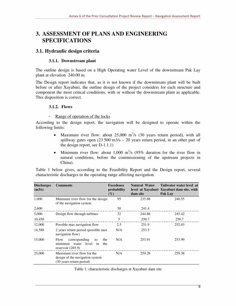
Table 1 below gives, according to the Feasibility Report and the Design report, several
characteristic discharges in the operating range affecting navigation.
Discharges
(m3/s)
Comments Excedence
probability
(%)
Natural Water
level at Xayaburi
dam site
Tailwater water level at
Xayaburi dam site, with
Pak Lay
1,000 Minimum river flow for the design
of the navigation system
95 235.88 240.55
2,600 50 241.4
5,000 Design flow through turbines 32 244.86 245.42
10,450 5 250.7 250.7
12,000 Possible max navigation flow 2.5 251.9 252.03
14,580 2 years return period (possible max
navigation flow)
N/A 253.5
15,000 Flow corresponding to the
minimum water level in the
reservoir (265.9)
N/A 253.91 253.99
25,000 Maximum river flow for the
design of the navigation system
(30 years return period)
N/A 259.28 259.38
Table 1: characteristic discharges at Xayaburi dam site

Annex 6 of the Prior Consultation Project Review Report – Navigation Assessment Report
7
- Comments
The maximum river flow for the design of the navigation system (25,000 m3/s, 30 years
return period flood) seems needlessly large. The transit of navigation should certainly have
stopped on the river for much lower flood flows, due to safety reasons.
On European large navigable rivers, it is usual to set the maximum navigable flow at the flow
exceeded statistically 10 days per year (excedence probability of 2.7%). Under the
hydrological conditions of the Mekong for the site of the Xayaburi dam, this flow is about
12,000 m3/s. On the Mekong river, considering the hydrological regime, with very
progressive and predictable gradients of flow growth, it is probably feasible and compatible
with safe navigation transit, to set the maximum navigable flow at a higher level, the 2 years
return period flood for example (14,580 m3/s at Xayaburi dam site).
Figure 6-3 of the Feasibility Report (monthly runoff of Mekong at Xayaburi dam) indicates
that values between 12,000 m3/s and 14,580 m3/s are suitable for ensuring smooth operation
of the navigable waterway. Indeed, under average statistical conditions, the mean monthly
discharge of 12,000 m3/s is never reached; under maximum statistical conditions the
maximum monthly discharge of 14,580 m3/s is only slightly exceeded in August and
September.
It should be noted that it will be necessary to adopt a definition of the maximum navigable
flow uniform over the whole navigable waterway.
3.1.3. Water levels
- Range of operation of the locks
According to the design report (B.3 and C.4), the navigation system is designed to operate
within the following limits:
� High operating water level (Upstream): 275.00 m a.s.l.
� Minimum operating water level (Upstream): 265.90 m a.s.l. (water level
in the reservoir prevailing with 15,000 m3/s flood).
� Minimum operating water level (Upstream), under transient construction
conditions : 255.5 m a.s.l.
� High operating water level (Downstream): 260.00 m a.s.l. (water level
corresponding to the proposed maximum navigation flow of 25,000 m3/s,
with the Pak Lay plant in operation)
� Minimum operating water level (Downstream): 236.00 m a.s.l.
- Comments
The range of water levels for operating conditions of the locks depends on the hypothesis
taken to set the maximum navigation flow.
As indicated above, the 25,000 m3/s flow seems too large. As a consequence, the high
operating water level for the downstream lock could be much lower.
• "peak flow" management
. While essentially conceived for a run of river operation, the plant should have the possibility
of a daily peaking operation in dry season, allowing daily fluctuations of the headwater and
tailwater levels. The Design Report provides for a 2.5 m operating range in the reservoir,
Annex 6 of the Prior Consultation Project Review Report – Navigation Assessment Report
8
which can be used for weekly peaking operations; thus, the minimum normal reservoir water
level for energy generation purposes is established at elevation 272.5 m.
Daily peaking can be expected to maximise revenue according to the power purchase
agreements. Normal peak period hours of 16 hours daily for six days and 72 hours weekly of
off-peak and transition period operations could be expected. The largest off-peak period is on
a Sunday when 24 hours are scheduled off peak. The storage available in the reservoir can be
used to reschedule flow from the off-peak to the peak periods resulting in a predominately
diurnal variation. Some weekly off-peak to on-peak scheduling will be possible during low
flow periods. During periods with river flow rate greater than 5140 m3/s there should be no
variation in the headwater level due to power generation operations.
Upstream of the dam, the lowering of the normal reservoir level to the elevation of 272.5 m
does not create difficulty for navigation transit, due to the very large available water depth
above the sill in normal conditions (24.5 m).
Downstream of the dam, especially during low water periods focused on by the developer and
in the situation where the Pak-Lay dam is not built, the transient reduction of the discharge at
the dam to permit filling the reservoir by 2.5 m will lead to fluctuating reductions of the level
downstream liable to reduce available water depth in the navigable channel close to the dam
and at the entrance of the lock downstream. The magnitude of these fluctuating reductions
must be evaluated in the different operating scenarios considered.
• Operation of the power plant
During the operation of the power plant, accidental stops of one or several turbines may occur
at any moment. Such stops create surges upstream and downstream the plant, whose
consequences on navigation should be assessed.
• Managing flood levels at Luang-Prabang.
The Design Report states that the head water level will be lowered during flood conditions to
mitigate the possibility of flooding at Luang Prabang.
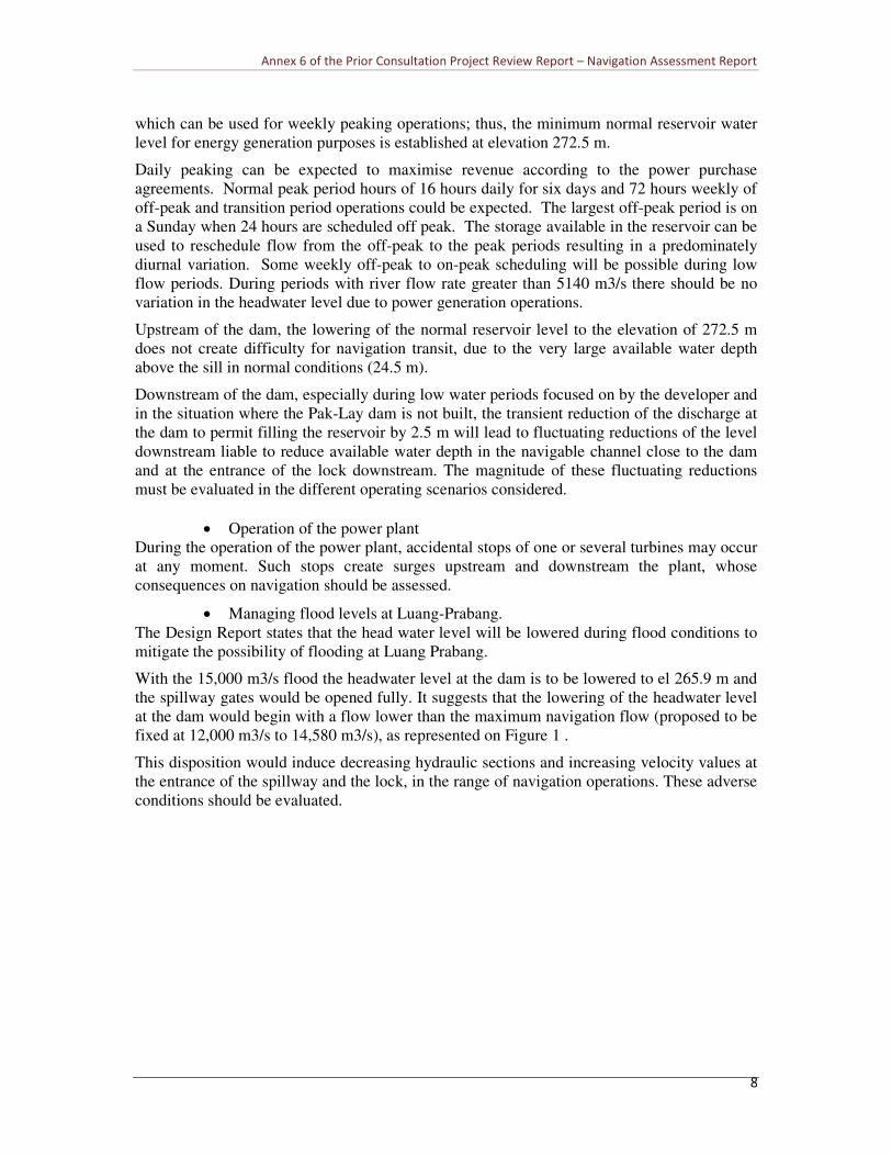
With the 15,000 m3/s flood the headwater level at the dam is to be lowered to el 265.9 m and
the spillway gates would be opened fully. It suggests that the lowering of the headwater level
at the dam would begin with a flow lower than the maximum navigation flow (proposed to be
fixed at 12,000 m3/s to 14,580 m3/s), as represented on Figure 1 .
This disposition would induce decreasing hydraulic sections and increasing velocity values at
the entrance of the spillway and the lock, in the range of navigation operations. These adverse
conditions should be evaluated.

Annex 6 of the Prior Consultation Project Review Report – Navigation Assessment Report
9
265.9
260
265
270
275
280
0 5000 10000 15000 20000 25000 30000 35000
m3/s
ele
vati
on
Figure 1: typical operation curve (upstream of dam)
3.1.4. Design vessels and navigation standards
The feasibility report states that the ship locks are designed for 500 T vessels, which is not
precise enough.
For the ship lock dimensions, the report “Standard specifications for ship locks on Mekong
mainstream dams” recommended to choose the following design vessel (adapted from PR of
China class IV standards):
- 2 x 500 DWT 109 m x 10.8 x 2 m
This recommendation is consistent with the Preliminary Design Guidance for the lock
dimensions (120 m x 12m x 4 m). Moreover, the general tendency in the long term on
navigable rivers is that shipping companies try to maximize the size of their boats by adapting
them to the dimensions of the locks.
Thus the design of Xayaburi dam project must take into account that ships or convoys up to
109 m long could transit through the locks.
The navigation channel and the approaches characteristics of the lock must be adapted to
Chinese class IV convoys 109 m long.
Chinese standards recommend minimum bend radius of 330 m for the navigation channel.
French standards for equivalent design vessels (650 to 1000 T, with 110 m locks) recommend
normal bend radius of 700 m and minimum bend radius of 450 m.
3.2. Nautical accessibility and approaches of the locks
The general arrangement of the main project structures, powerhouse, spillway and lock, is
correct. The powerhouse is situated in the outer side of the river bend, whereas the lock is
located in the inner side, which is common practice.
However, in the future situation after commissioning of the dam, the navigation accessibility
needs to be improved, because of some adverse characteristics of the site, as said in 3.2.2
below.
Annex 6 of the Prior Consultation Project Review Report – Navigation Assessment Report
10
During construction, the Design Report states that navigation shall be maintained, except for
the month when the second stage pre –cofferdams across the river will be built. Indeed, there
is no other technical solution for this short period and the interruption has to be accepted.
3.2.1. During the construction
The feasibility report proposes the construction of the structures in two stages.
During the first phase, lasting about 3 years, the dam and lock will be built behind a
provisional cofferdam constructed in the main channel of the river, in the area of the alluvial
plateau located on the bend where the dam project is located. This cofferdam projects from
the right bank by about 250 m into the main channel of the river, up to the bend at level (245).
During this first phase, navigation will continue in the low water channel of the river, on the
left bank of the bend.
The cross sections of KM 1931.1 and 1930.7, supplied in the Feasibility report (Figure 4-7)
allow evaluating the consequences of this long provisional phase (3 years) on the flows in the
river and, consequently, on navigation.
Up to 245 (i.e. up to a discharge of 5,000 m3/s, exceeded statistically for 70% of the year), the
provisional cofferdam has almost no impact on the river flows. The current velocity is the
same as in the present situation (i.e. about 2.3 m/s at KM 1930.7) and navigation is not
disturbed.
For discharges higher than 5,000 m3/s, the entire discharge is concentrated in the low water
channel, instead of partially overflowing onto right bank. The increase of average velocity of
the flow therefore makes passage by navigation more difficult. The developer will have to
precisely evaluate this increase in velocity throughout the whole range of discharges where
navigation now operates on the river.
If necessary, this increase in average velocity could be reduced by dredging the bed of the low
water channel during the first phase of construction.
During the second phase, the lock will be commissioned while the hydropower plant is being
built on the left bank, behind another cofferdam. During this phase, the level of the floor of
the lock upstream must be compatible with the passage of navigation with damming at the
spillway crest (254). The design report states that the minimum water level when the river is
diverted over the spillway is 255.5. This level of 255.5 will allow the normal water depth of 5
m at the entrance upstream of the lock.
3.2.2. After the commissioning of the dam
The lock is correctly located next to the spillway, and at first glance, sufficiently far from the
plant to limit the impact of fluctuating levels due to starting and stopping the turbines
(although it needs to be confirmed by specific calculations of potential surges, as said before).
The downstream part of the lock is separated from the spillway by a dividing wall; it should
be checked that it is sufficiently long to limit the effects of turbulence caused by the flow.
In the absence of a general plan making it possible to show the layout of the navigable
channel long enough upstream and downstream of the lock (2 km), it is difficult to correctly
analyse the quality of access for the boats.
Annex 6 of the Prior Consultation Project Review Report – Navigation Assessment Report
11
At first glance, access downstream does not raise any geometric or hydraulic problems; a plan
and sections should nonetheless specify the width and depth available during periods of very
low water (236), in the situation where the Pak Lay dam is not built.
On the contrary, access upstream of the lock appears to be inadequate.
Due to the hill projecting from the alignment of the right bank, 800 m upstream of the lock,
the bend radii of the access channel are much too small for the gauges of the boats likely to
use the river in the future (about 350 m whereas the normal bend radius should be 700 m).
For discharges lower than the maximum powerhouse flow, the current leads towards the
powerplant and its mean velocity is rather low. By following a route on the right side of the
river where the velocity is very low, boats should be able to turn quite easily towards the
entrance of the lock.
For discharges higher than 5,000 m3/s (excedence probability of 30%), the boats will be
obliged to slow down and be positioned at an angle close to 45° crosswise to the current
towards the spillway, which seems dangerous. The least problem, of motor for example,
could cause them to be drawn towards the spillway.
Moreover, upstream, the layout of the site leads to conclude that the velocity field hardly
favours navigation, at least for discharges higher than 5,000 m3/s.
The slope of the hill on the right bank, 800 m from the dam, will undoubtedly cause a shift of
the flow detrimental to the efficient distribution of the discharge in the spillway and liable to
generate reverse flows in the upstream outer port of the lock, as shown on Figure 2.
With a maximum navigation discharge of 12,000 m3/s to 15,000 m3/s, the current velocity
upstream of the spillway, theoretically in the region of 1m/s to 1.9 m/s on average for a
perfectly homogenous supply to all the gates of the spillway, could be locally stronger (up to
2.5 m/s ?) and lead to cross currents exceeding the threshold normally admissible for
navigation.
The reverse currents in the upstream outer port will also increase the risk of sedimentation and
the accumulation of floating debris.
In conclusion, it is necessary to perform a more in-depth study of the navigation access
upstream of the lock.

Annex 6 of the Prior Consultation Project Review Report – Navigation Assessment Report
12
Figure 2 : scheme of the velocity field, upstream of the lock
3.3. Lock design
3.3.1. Chamber dimensions
The guidelines recommend for the useful dimensions of the chambers: length 120 m; width
12.00m; water depth 4.00 m (+1.00 m safety margin for long term bend incision). Air
clearance (under the bridges) is not specified in these guidelines.
In the design report (§ C4.1 – General), it is indicated ‘’for vessels of 120 m in length, 12 m
wide and provide a minimum depth of 5m’’.
Obviously, these dimensions are not for the vessels but for the useful dimensions of the
chambers.
Further in the same part of the report, the data sheet describing the two chambers indicates for
the upstream chamber, length of lock 144 m and for the downstream chamber length of lock
154 m above el. 250.5 and length of lock 139 m below el. 250.5.
- Comments
There must be no confusion between the dimensions of the ships and those of the chambers,
nor with the total and the useful dimensions of the chambers. The total length include the
opening stroke of the gates leaves, the recesses for stoplogs, the opening stroke of the safety
devices, … The useful length of the chambers must be measured between safety devices.

Annex 6 of the Prior Consultation Project Review Report – Navigation Assessment Report
13
The documents of the developer must confirm the useful dimensions of the chambers.
According to the plans, the proposed locks present the useful dimensions 120 m x 12 m
specified by the guidelines.
Apparently, there are even several meters of safety margin between the two security devices
of both locks.
3.3.2. Air clearance
Air clearance above highest navigation level is not specified in the guidelines. However, it
can be noticed that this characteristic is nearly 12 m under the downstream bridge, and far
more under the upstream bridge. The air clearance of 12 m seems correct but needs to be
compared with the other constraints along the navigable waterway.
3.3.3. Water depth
As said above, the requested minimal water depth is 4.00 m, with a safety margin of 1 meter
for bed incision downstream. It has to be reminded that the required 4 m water depth takes
into account the necessary submergence above the outlets of the emptying and filling system
and the allowance for prevention of vessels striking the sill.
The design report states:
- Bottom of lock (downstream chamber) : 231.00
- Bottom of lock (upstream chamber) : 250.50
According to the outline design drawings, the approaches are at the same elevation as the
bottoms of the locks, which is correct.
- Comments
With reference to the range of variation of water levels (see above), the available water depth
is always equal or larger than 5 m.
Downstream, for very low flows (under 1,000 m3/s) and without the construction of Pak Lay,
the available water depth could be a little less than 5 m during short periods, but this depth
takes into account long term bed incision that could be controlled by the retention level at Pak
Lay (240.00).
If the construction of Pak Lay dam is decided, there will be no problem of water depth.
Upstream, during the second stage of construction, the minimum provisional retention level
will be 255.5, allowing 5 m water depth. 4 m water depth would be enough because it is no
use foreseeing 1 m of safety margin for bed incision in this transient situation.
After completion of the scheme, the minimum upstream level will be 265.90 m, allowing 10.4
m water depth, far more than the minimum requested.
3.3.4. 2nd
Set of locks
With reference to the outline design drawings, the second set of locks axis seems too far from
the first one and thus leads to a lot of blasting and earthworks. In addition, this disposal leads
to complicate the navigation, especially upstream: the upstream straight alignment of the lock
is far from the two lengths of the ‘’maximum’’ ship (109 m). Furthermore, the radii of the
bends are too small.

Annex 6 of the Prior Consultation Project Review Report – Navigation Assessment Report
14
It is recommended to build the second lock side by side with first one: the right bank wall of
the first set of locks would be designed and built as a separation wall of the two sets, and be
used as the eastern part of the cofferdam when building the second set of locks.
3.4. Lock equipment
3.4.1. Gates
The 3 chamber gates belong to the mitre gate type. This kind of gate is adequate and largely
used, all over the world. They are proven technology. So are the manoeuvring devices:
servomotors and hydraulic units.
Filling and emptying gates are flat fixed wheel gates, operated by hydraulic jacks, which is an
usual solution in European locks. An alternative (USA) is to use sliding gates equipped with
synthetic material with smooth friction ratio.
- Comments
The text and drawings show that the top levels of the upstream and middle gates are
respectively 276.00 and 280.00. The PMF upstream level is 278.30. The left wall elevation is
280.00 up to the downstream part of the spillway gate. With these indications, we understand
that the middle gate assures the protection of the sole downstream lock against extreme
floods. With this disposition, the upstream gate is overtopped by 2.30m during extreme
floods, introducing debris in the upstream chamber
It is recommended to raise the upstream gate up to 280.00 (+4.00m) and lower the middle
gate down to 276.00 ( - 4.00m ). The upstream gate will then protect both chambers from the
extreme floods and avoid the introduction of debris in the upstream chamber.
3.4.2. Safety devices
Stoplogs slots are correctly designed at the chamber gates and the water feeding system gates
for reparation and maintenance.
To improve the availability and the safety of the feeding system, each system (stoplog / gate /
stoplog) may be replaced by a system (gate / gate / stoplog).
Gate protection is foreseen with arrester cable systems. For example, this system is commonly
used in Italian locks of similar dimensions. The system must be dimensioned for the size,
capacity and speed during impact of the vessels or convoys. The XB – 1214 drawing indicates
: ‘’the following equipment is in the scope of the subcontractor for hydro-mechanical
equipment: arrester cable system, flotting mooring bit’’.
It can be noticed that the upstream gate of the upstream lock is not protected against the ships
sailing downwards, nor the downstream gate of the downstream lock against the ships sailing
upwards.
3.4.3. Other equipment
• Mooring devices
It can be seen on the drawings, for each lock, and both sides:
- 4 lines of vertical fixed hooks
Annex 6 of the Prior Consultation Project Review Report – Navigation Assessment Report
15
- 5 lines of floating bollards
- 9 fixed bollards on top of walls
- Comments
The maximum distance between two mooring devices is 15 m, enough to moor the ships with
two ropes or cables.
The usefulness of the lines of fixed hooks between the gates and the security device is not
very clear.
The mooring posts in approach channels must be equipped with mooring bits, all along the
range of water levels
• Access to the bottom
3 ladders along the lines of hooks allow the small vessel follow the up (or down) rising of the
water level.
One of them, on each side, must be lowered in order to allow access to the bottom of the
chamber when empty.
3.5. Emptying and filling system of the locks
3.5.1. Hydraulic boundary conditions
According to the design report, the minimum water level of the downstream channel is 236.00
and the maximum water level in the upstream channel is 275.00 m. The two steps-locks
system will consequently meet the following initial heads:
- Filling of the upper lock from upstream channel: maximum initial head of 19.5 m
- Filling of lower lock from upper lock : maximum initial head of 39 m
- Emptying lower lock in downstream channel: maximum initial head of 19.5 m
These ranges of initial heads correspond to “High lift lock” class requesting a bottom Filling
- Emptying (F-E) system with multiple ports distributed uniformly in throughout the lock chamber in order to limit the turbulence and surging, thus avoiding excessive hawser
forces and allowing a safe filling and emptying of the lock chamber.
The proposed type of F-E system is consequently suitable for the range of initial heads but
still needs to be improved to respect the maximum target times and the redundancy principle,
as explained in 3.5.4 and 3.5.5 below.
3.5.2. Operation reference time
As per the point 29 of the Preliminary Design Guidance, the “total time for a complete
lockage” shall not exceed 50 minutes for a two-step locks system.
The design report (B3.3.3) gives a breakdown of the total transit time:
- Moving from the approach channel to the first lock and securing the boats: 10
minutes
- Raising / lowering the first lock: 10 minutes
- Moving from the first lock to the second and securing the boats: 10 minutes

Annex 6 of the Prior Consultation Project Review Report – Navigation Assessment Report
16
- Raising / lowering the second lock: 10 minutes
- Moving from the second lock to the approach channel: 10 minutes
Generally, this type of breakdowns exhibits the times used for gates manoeuvres.
In the D.1.1.2, it is indicated that the mitre gates opening / closing speed is 3mn.
So the “50 minutes” target time can be split as followed, in Table 2:
Operation Reference
time in
minute
Comment
1 Vessel approach 6 The downstream gate is opened during the vessel
approach
2 Downstream gate closure 3 The ship is moored during the gate closure
3 Lower Lock filling 10
4 Middle gate opening 3 The ship is unmoored during the gate opening
5 Vessel transfer to the upper lock 6
6 Middle gate closure 3 The ship is moored during the gate closure
7 Upper Lock filling 10
8 Upstream gate opening 3 The ship is unmoored during the gate opening
9 Vessel exit 6
Lockage sequence duration in
minutes
50
Table 2: transit times through the locks
These operation times (that should be confirmed with the same level of details by the
developer) seem realistic and confirm the target time of 10 mn for the operations of filling and
emptying the chamber locks.
The design report states that the filling – emptying system will be conceived to achieve the
maximum filling and emptying times of 10 minutes (C4.5) except perhaps for maximum
differential head conditions. These limitations, that could be acceptable only in very specific
hydrological situations, for example very low flows without Pak Lay, must be more detailed
and require in depth studies with a physical model.
3.5.3. Filling and emptying system features
The F-E system proposed is composed by:
- One lateral culvert, 4.20 m (H) x 3.20 m (W),
- Seven transversal culverts (called Diffuser) connected to the lateral culvert, 1.50 m
(H) x 2.00 m (W), each diffuser being equipped with five openings 1.60 m x 2.00

Annex 6 of the Prior Consultation Project Review Report – Navigation Assessment Report
17
m. The entrance section of the diffuser (connected to the lateral culvert is 1.50 m
(H) x 1.20 m (W)).
- Three gates 2.80 m (H) x 3.20 m (W),
- Three water intake allowing to feed the upper lock from the upstream spillway
approach channel, 4.20 m (H) x 4.00 m (W) ?
- Four outlets allowing to empty the lower lock in the downstream spillway
approach channel.
3.5.4. Possible improvements of the F-E system
• Lateral culvert, diffuser and openings
In order to achieve a balance distribution in the seven diffusers the ratio (sigma lateral) between
the total cross-sectional area of the diffuser to the cross-sectional area of the lateral culvert
should be about 1 which is more or less the case:
94.020.4*20.3
20.1*50.1*7==lateralσ
The ratio between the total cross-sectional area of the openings to the cross-sectional area of
the diffuser should also be about 1 in order to achieve a balance distribution between the five
openings:
33.500.2*50.1
00.2*60.1*5==diffuserσ
The sigma ratio is well above 1 meaning that the size of the openings is too large with respect
to the dimension of the diffuser. The flow will not be homogenous between the five openings
of each diffuser.
Moreover, the sudden enlargement of the diffuser width (from 1.20 m to 2.00) without
hydraulic shape (i.e. rounded shape or smooth transition) will generate high head losses and
will disturb the feeding of the first opening.
• Gates in the lateral culvert
The three gates dimensions are smaller than the lateral culvert dimensions, the lateral culvert
height being reduced from 4.20 m to 2.80 m upstream to the gate section and being enlarged
form 2.80 m to 4.20 m downstream to the gate section (except for the gate closest to the outlet
since the lateral culvert height is kept at 2.80 m).
A gate section smaller than the culvert section is not advocated (especially for high lift locks)
since it leads to increase the velocity in the valve section and consequently reduce the
pressure, increasing the risk of cavitation occurrence.
In addition, this reduction/enlargement also leads to increase the total head loss of the system
reducing the F-E time.
Finally there is no redundancy of the gates, meaning that the outage of one gate will lead to
the outage of all the locks system.
• Water intakes in the upstream spillway approach channel
The total section of the water intake seems to be sufficient to limit the entering flow velocity
under 1.5 to 2 m/s. Anyway, the greater the intake section is, the lower is the intake head loss.
Annex 6 of the Prior Consultation Project Review Report – Navigation Assessment Report
18
The intake should be better set in the nose of the separation wall and not perpendicularly to
the flow in the upstream channel
In order to limit the head losses, the intakes should be located at the same elevation than the
upper gate since it will suppress one 45 ° bend. This will also increase the submergence of the
intake, thus reducing the possible risk of air entrapment or vortices occurrence for low water
level in the upstream channel. If there is any risk of sediments or debris entrainment in the
culvert, the water intake bottom sill can be slightly raised from the upstream channel bottom.
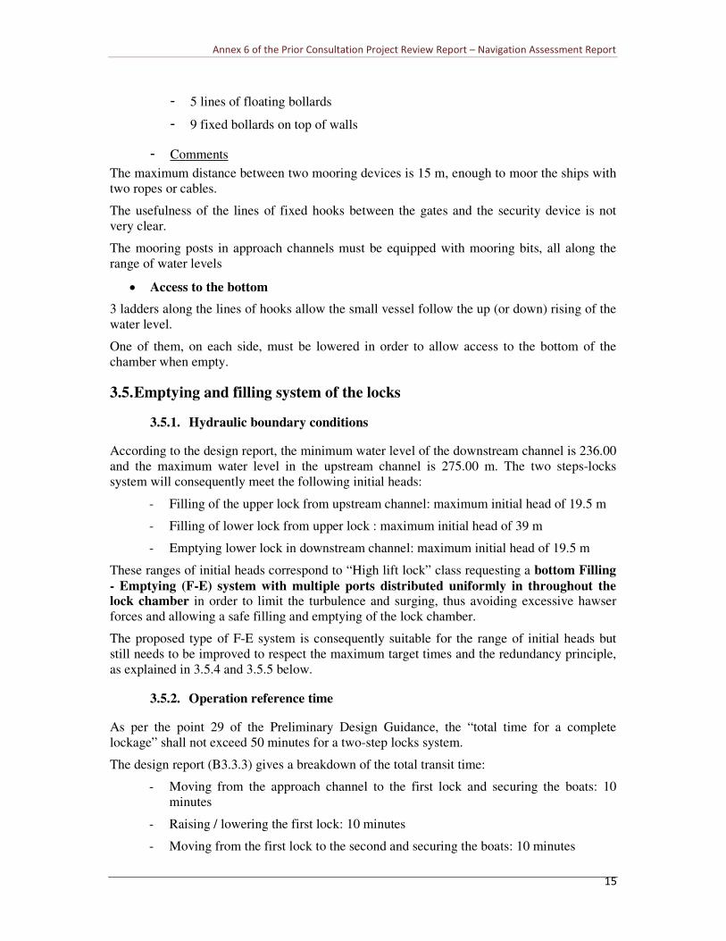
• Outlets in the downstream spillway approach channel
The proposed shape (90° turn) of the outlets is not efficient in order to achieve a balance
distribution of the four outlet sections. The major part of the flow will be spilled by the
downstream section while no discharge will pass through the upstream one as shown in the
Figure 3 hereafter (N.B.: this outlet layout has already been tested at CNR hydraulic
laboratory during the physical model study of the Cremona lock (Italy) and has been proved
to be inefficient with respect to the flow distribution).
Figure 3: scheme of heterogeneous distribution of flow
As well as for the intakes, the outlets should be located at the same elevation than the upper
gate since it will suppress one 45 ° bend and reduce the total head loss.
The total section of the outlet should also be design as large as possible in order to limit the
velocity of the exiting flow, thus limiting the outlet head loss and preventing important
turbulence in the lock downstream channel. Indeed high flow velocity (i.e. more than 2.5 m/s)
may disturb the navigation and lead to scouring in the opposite bank).
3.5.5. Maintenance easiness of the emptying and filling system
The proposed F-E system is not optimised with respect to the limitation of the lane outage
since there is no redundancy of the critical equipment such as culvert gates.
If any problem occurs on a culvert gate, the complete lane will have to be closed, stopping the
navigation during the repair works.
Since the system is equipped with only one lateral, culvert, the same conclusion can be drawn
if something occurs in the lateral culvert. A two lateral culverts F-E system would be better.
The problem of sediments deposit (and debris if any) in the F-E system have also to be taken
into account, especially in the low velocity section, since it can increased noticeably the
maintenance time.
Annex 6 of the Prior Consultation Project Review Report – Navigation Assessment Report
19
4. OUTLINE RECOMMENDATIONS ON PLANS AND
SPECIFICATIONS
4.1. Hydraulic conditions
• The maximum navigable discharge should be fixed, according to hydrological
conditions. A flow close to 2 years return period flow could be chosen in the case of
the Mekong River. The corresponding Highest Navigable Level (HNL) should be
clarified downstream of the lock, in the situation prevailing before the construction of
Pak Lay dam.
• The operation curve, giving the water levels upstream of the lock corresponding to the
discharges in all situations of operations of the dam, normal, during peak flows, during
flood events, should be given. The Highest Operational Level should be given.
• The surges generated by special operations of the power plant (peak flows, emergency
stop of turbines…) should be calculated, especially the minimum stages downstream
of the dam, before the construction of Pak Lay dam.
• Many discrepancies exist concerning the values of operational or navigable values. All
levels have to be indicated as ‘’operating’’ or ‘’navigable’’ It is recommended to build
a general table (data sheet) gathering the right highest and minimum navigable flows
and levels (for water and structures) under the different stages (natural, construction,
after commissioning) and scenario (with and without Pak Lay), for upstream &
downstream levels.
4.2. Design vessel and navigation standard
• The design should take into account the 2x 500 T (109 m x 10.8 m x 2 m) design
vessel for the channel characteristics. For such a vessel, the international standards
recommend normal bend radius of 700 m and, exceptionally, minimum bend radius of
450m.
• It is recommended to adopt straight alignments of at least two times the maximum
vessel length for entrance and exit, and at least one time the maximum vessel length
between two bends
4.3. Nautical accessibility
• The consequences of the first phase of construction (flow concentrated in the low flow
river bed) on the velocities in the natural navigation channel should be evaluated, for
flow conditions presently compatible with ship transit. Compensatory dredging could
be considered, if the velocities are too much increased.
• The navigation channel plan should be drafted 2km upstream and downstream the
locks, with all the geometrical characteristics (width, draught, bend radii, , alignments,
width allowance in the bends, …).
• The design of the upstream approach of the lock seems not safe for navigation. The
bend radii are too small and the manoeuvres imposed the ships coming from upstream
Annex 6 of the Prior Consultation Project Review Report – Navigation Assessment Report
20
are tricky during situations of high flow toward the spillway. The flow conditions
upstream of the lock are likely to provoke sedimentation and accumulation of floating
debris in the lock entry. For all these reasons, the removal of the outcrop situated 800
m upstream of the lock, on the right bank should be seriously considered.
• An in –depth study of the nautical and hydraulic conditions upstream and downstream
of the dam should be performed, including the construction of a physical model. This
study should take into account standard and non – standard operation configurations of
the main works (spillway and power plant).
4.4. Lock design
• The design report must confirm the useful dimensions of the lock chambers
• The minimum air clearance has to be compared to the other constraints along the
navigable waterway
• The design of the second set of locks is not acceptable. It is recommended to design
the second lock side by side with first one.
• The elevation of the upstream mitre gate has to be increased to protect all the lock
chambers against extreme floods (in order to limit maintenance operations after the
flood).
• The dimensioning of the arrester cables has to take into account the capacity of the
largest ships or convoys (1,000 T)
• The mooring posts in approach channels must be quipped with mooring bits
• One ladder on each side of the lock chambers have to allow access to the bottom for
maintenance purpose.
4.5. Emptying and filling system
• Considering the high head of the locks and the necessity to limit the emptying and
filling time, the proposed emptying and filling system is not the more appropriate one.
Feeding and emptying flows vary all along the longitudinal culvert and then on the
different ports on each transverse culvert. The injection of flows is therefore
asymmetric, longitudinally and transversally, leading the ships to move erratically in
the chambers. There is no redundancy of critical equipment (gates, culverts). A system
with two longitudinal culverts and several transverse culverts in staggered rows, such
as that represented in Figure 4 is recommended.

Annex 6 of the Prior Consultation Project Review Report – Navigation Assessment Report
21
chamber
• The geometry of the filling-emptying system has to be modified according to
observations made in 3.5.4 above. An in-depth study with a physical model of the
filling-emptying system is compulsory.
Figure 4: schematic plan view of a hydraulic feeding system with 2 lateral culverts

Annex 6 of the Prior Consultation Project Review Report – Navigation Assessment Report
22
5. OUTLINE RECOMMENDATIONS ON HOW TO FINANCE
THE LOCK OPERATIONS
5.1. Benchmark
The most pertinent references are those relating to locks linked to hydropower plants in the
framework of a global development.
However, it is also interesting to focus on the tolls practiced on certain European navigable
waterways, especially for examining how these tolls are structured.
On the French portion of the Rhine, a major river for international transport, the passage of
locks linked to hydropower plants built and managed by EDF in the framework of a 60 year
concession, is completely free. The lock personnel nonetheless belong to EDF.
On the Rhone, a river developed and operated in the framework of a 75 year multipurpose
concession including hydroelectricity production and navigation, the concessionary,
Compagnie Nationale du Rhône (CNR), does not collect any tolls for the passage of boats
through the locks, although the lock personnel belong to CNR.
The specifications of CNR's concession demand that boats should be locked as soon as they
appear at the lock, except small craft which can be made to wait in order to form a grouped
passage. This waiting period lasts about 45 min., whereas lockage takes about 30min. For
night lockages, the only obligation that boats must satisfy is that the locks must be warned of
their passage shortly beforehand outside normal hours.
On the Rhone, the global cost of operation and maintenance relating to navigation structures,
locks and navigable channels, amounts to about 2% of its annual turnover. As mentioned
above, this cost is paid for by CNR, the concessionary, and is therefore paid, indirectly, by the
hydroelectricity consumers.
However, on the Rhone, as with the whole network of French waterways, Voies Navigables
de France (VNF), the French national entity responsible for navigable waterways in France,
collects a toll based on the quantity of tons x kilometres travelled by the boat for every trip,
whatever the number of locks crossed. Each transporter has to declare its itinerary and the
quantity of tons transported to VNF beforehand.
In France, excluding the Rhone, a special lockage fee is also applied for hours outside normal
lock operating times. In these cases, the boat must have provided prior notice of its passage to
the locks (generally the day before). This special fee varies according to the gauge of the boat
and its type (river-maritime, self-propelled or push-tow convoys, passenger boats, individual
pleasure craft).
By way of example, the total amount in tolls collected for the entire network managed by
VNF is €13 million, i.e. only 10% of the operating expenses of this public establishment.
Indeed, VNF has other much richer resources, collected for other types of waterway use (a fee
for water intakes, fees for the use of its property) that allow it to balance its budget.
On the wide gauge waterway of the Moselle River, an international river developed for
navigation from public funding, tolls are collected for each country crossed. These tolls are
either traffic tolls, or lockage fees.
The traffic tolls are calculated according to the distance of the trip:
Annex 6 of the Prior Consultation Project Review Report – Navigation Assessment Report
23
• for loaded goods boats with a minimum capacity of 15 tons, according to the weight
and type of goods transported
• for goods boats transporting loaded containers independently of the weight and type of
goods transported, according to the number of containers and their dimensions
• for passenger boats and hotel-boats with passengers on board according to the
maximum number of passengers authorised or to the number of beds installed on
board.
Lockage fees are collected at each passage through a lock:
• small craft weighing less than 15 tons.
• for special boats (other than types subjected to traffic tolls) weighing over 15 tons:
ferries, dredgers, construction boats, houseboats, etc., according to the surface area of
the water in the chamber of the lock.
In order to offset the technical disadvantages occurring after low water periods on the Rhine
(a free flowing river at its confluence with the Moselle), goods tolls are reduced by 50% when
the Rhine is under a reference level.
The level of the tolls on the Moselle is intended not to discourage the development of river
transport, considered as favourable for sustainable development, that is to say that it is far
from covering the operating expenses of each country.
With this benchmark relating to France, the following noteworthy elements can be
highlighted:
• when locks are linked to hydropower plants under concession, the concessionary does
not receive any fee for operating and maintaining the locks. The level of service
imposed on the concessionary is high. These expenses are taken into account from the
outset in the economic balance of the concession. Nonetheless, it should be
emphasised that, in the two examples mentioned, the concessions are for very long
periods (60 and 75 years) and the concessionaries, EDF and CNR, are companies with
mostly public capital, and in the case of multipurpose hydropower schemes, wholly
public.
• It is usual for the public organisations responsible for operating modern navigable
waterways to collect a toll from users.
• Given the dimension of public service inherent to networks of navigable waterways
and the acknowledged advantage for territorial development of using these waterways
for transport (alleviating road traffic, low CO2 emissions, etc.), the toll is set at a much
lower level than the cost of operating and maintaining the structures.
• The pricing levels are adapted to the type of boats, in order to take into account the
resources of each user.
• An additional price can be applied for a special service (for example, lock passages
outside normal operating hours or rules).
• A reduction can be applied to the toll when the level of service of the entire navigable
waterway is below the level expected.

Annex 6 of the Prior Consultation Project Review Report – Navigation Assessment Report
24
5.2. Recommendations
5.2.1. Principle of lockage fee
In the light of the examples mentioned previously, the principle of practising a lockage fee for
crossing the locks appears advisable.
It allows showing the users that there is a cost in operating the locks and avoiding abusive use
(over-frequent toing-and-froing from upstream and downstream of the dam).
It is also interesting to link this fee with a requirement for quality from the users. This
requirement for service quality must be clearly specified in the operator's specifications:
normal operating hours, waiting time according to the type of boat and according to the flow
regime (it is possible to envisage reducing the number of lockages during very dry periods in
order to save water for the hydropower turbines), and closed periods for maintenance. The
rules could be modified gradually as traffic on the navigable waterway increases.
In the specific case of the Xayaburi dam, the fee could be collected by the Laotian
administration in charge of navigation. The fees could help it to uphold control over ensuring
good service levels provided by the locks.
Regarding this, it is necessary to include in the specifications given to the concessionary, the
stipulation that the administration must have the means to control lock service quality in real
time, for example, by making available on the internet the data pertaining to such service
quality: number of lockages and the time between each one, the number and types of boats
locked, especially available water depth upstream and downstream of the lock (taking into
account the fluctuations liable to be caused by the daily peaking operation in the dry season).
In return for the concessionary, and to take into account the fact that its concession is much
shorter than the European references mentioned above, it will be necessary to formulate rules
allowing it to limit the number of lockages to an economically and practically reasonable
level and set up a pricing grid that encourages users to behave wisely (see the suggestions
below).
5.2.2. Level of lockage fees
The European examples clearly show that it is not realistic to set the toll with the intention of
balancing lock operating expenses.
It is recommended to set a price level as a function of type of user and their level of solvency.
This price grid must be agreed by the Laotian government.
Later, if other dams are built on part of the river flowing through neighbouring countries, this
grid could be applied jointly for the whole river and approved by an authority representing all
these countries.
It is not within the scope of this study to propose the amounts of these fees, though it does
appears advisable to distinguish the following categories of boats in the price grid:
• loaded goods boats: fee according to the tonnage transported,
• passenger boats: fee according to the number of passengers transported,
• container barge (when they start operating): fee according to the number of containers,
• small craft (size threshold to be defined according to current local traffic): symbolic
fee but waiting in order to group craft in the lock chamber.

Annex 6 of the Prior Consultation Project Review Report – Navigation Assessment Report
25
The number of lockages performed during lock operating hours should be adapted to the level
of commercial traffic. Initially, a wait in the region from one to one and a half hours and at
most for a total lockage time of 45 min seems, at first sight, to be economically admissible.
This means from 5 to 6 lockages per day during normal opening period of 12h. Following
this, this waiting time should be shortened gradually as traffic increases.
In line with this principle of maximum waiting time, it is advisable to set up a special, higher
fee for boats that do not want to wait to cross the locks or cross them outside normal operating
times, but cross them by appointment. This could be the case of passenger boats, taking into
account the development of tourist traffic on the Mekong. Logically, this pricing policy
combined with a higher service level resulting from the specifications and difficult to predict,
should be collected by the concessionary.