Embed Size (px)
Citation preview

28 February 2014 1
ANNEX B DOCUMENT
PROPOSED VENTILATION SYSTEM AT
9 The Quadrant, Buxton, Derbyshire. SK17 6AW
Prepared in conjunction with SUMMIT DESIGN LTD

28 February 2014 2
CONTENTS:
1.0 INTRODUCTION 2.0 PREAMBLE TO SPECIFICATION 3.0 INFORMATION ON PREMISES & TYPE OF OPERATIONS 4.0 PLANS AND DRAWINGS 5.0 DETAILED DESIGN OF VENTILATION SYSTEM
5.1 Pre-filters
5.2 Electrostatic precipitators
5.3 Carbon Filters
5.4 Odour counteracting or neutralising system
5.5 Cooker Hood details 5.6 System operation
5.7 Flue design
5.8 Noise
5.9 Maintenance
6.0 ADDITIONAL NOTES FOR GUIDANCE APPENDIX 1 – Coldroom and Airconditioning compressor data sheets
APPENDIX 2 – Further details on Carbon filters and maintenance
programme
APPENDIX 3 – Supporting Data sheets
28 February 2014 3
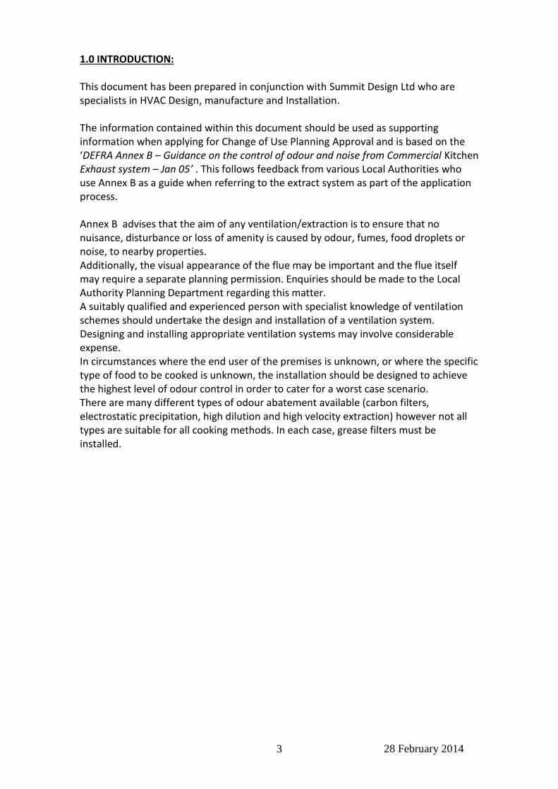
1.0 INTRODUCTION: This document has been prepared in conjunction with Summit Design Ltd who are specialists in HVAC Design, manufacture and Installation. The information contained within this document should be used as supporting information when applying for Change of Use Planning Approval and is based on the ‘DEFRA Annex B – Guidance on the control of odour and noise from Commercial Kitchen Exhaust system – Jan 05’ . This follows feedback from various Local Authorities who use Annex B as a guide when referring to the extract system as part of the application process. Annex B advises that the aim of any ventilation/extraction is to ensure that no nuisance, disturbance or loss of amenity is caused by odour, fumes, food droplets or noise, to nearby properties. Additionally, the visual appearance of the flue may be important and the flue itself may require a separate planning permission. Enquiries should be made to the Local Authority Planning Department regarding this matter. A suitably qualified and experienced person with specialist knowledge of ventilation schemes should undertake the design and installation of a ventilation system. Designing and installing appropriate ventilation systems may involve considerable expense. In circumstances where the end user of the premises is unknown, or where the specific type of food to be cooked is unknown, the installation should be designed to achieve the highest level of odour control in order to cater for a worst case scenario. There are many different types of odour abatement available (carbon filters, electrostatic precipitation, high dilution and high velocity extraction) however not all types are suitable for all cooking methods. In each case, grease filters must be installed.

28 February 2014 4
2.0 PREAMBLE TO SPECIFICATION Please note that the proposed cooking operation produces very little grease and the extract system is predominately removing heat and gas combustion fumes. All work is carried out in accordance with the latest relevant British (or Irish regulations where applicable) and European Standards, statutory Regulation and Byelaws together with the following publications: CIBSE Codes and guides to current practice Water Authority By Laws HVCA – DW143 Practical Guide to Ductwork Leakage Testing HVCA DW144 Specification for Sheet Metal Ductwork HVCA DW172 Guide to Good Practice for Kitchen Ventilation Systems HVCA – RUAG70 Guide to Good Practice Refrigeration The Building Regulations Gas Safety (Installation and Use) Regulations 1998 All plant, ducts, pipe cables etc. shall be adequately protected against accidental damage corrosion and external environment and shall be capable of safe decontamination and removal in the future without disturbing other services. Pipes and ducts shall be adequately sized, kept as short as practicable, leak-proof with a minimum number of joints and have provision for routine maintenance. All facilities shall be designed to prevent the ingress or egress of rodents, vermin, and insects. The duct will be fixed to the shell of the unit using anti-vibration fixing mounts and under no circumstances will flexible ductwork be used other than the fan connections The HVAC contractor shall supply the client with system design drawings, prior to manufacture and installation For projects in England and Wales, the HVAC contractor shall also demonstrate compliance with Building Regulations Approved documents L2A & L2B. This will include:
(a) Provision of details of the efficiency and controls of heating , cooling and ventilation systems in accordance with Non-Domestic Heating, Cooling and Ventilation compliance Guide (2006)
(b) Provision of commissioning certificates including air leakage tests on the ductwork Fire/smoke dampers shall be installed in all fire compartment walls to Building Control requirements The HVAC contractor shall ensure that externally the ductwork conforms to the supplied drawings in terms of its route, height and termination. These drawings will have formed part of our Planning Approval and must not be deviated from without express permission from the Project Manager Upon completion of the installation, all shall be fully tested and proved including airflows. The contractor shall produce an Operating and Maintenance Manual which shall contain details of all equipment supplied, a record drawing of the complete mechanical services installation and copies of all Test Certificates. It shall contain a Maintenance Schedule based on the manufacturer’s recommendations.

28 February 2014 5
3.0 INFORMATION ON PREMISES AND TYPE OF OPERATIONS The proposed unit is situated within an existing parade of retail units. For your information, approx. 100 meals on average per day will be produced and the method of preparation and cooking is through hand preparation and dry baking. Meal types served are pizza and oven bakes side dishes The proposed hours of operation of the business and ventilation plant will be in accordance with the hours stated in the approved Change of Use 4.0 PLANS AND DRAWINGS Please refer to Hattrell DS One drawings No. 4900-A5-02 and A5-04 of the proposed premises which shows the indicative internal and external arrangements and location of the ventilation system. Please refer to these drawings for elevations of the unit. A schematic drawing produced by the HVAC Designer will be provided at a later date. 5.0 DETAILED DESIGN OF VENTILATION SYSTEM 5.1 Pre-filters - Fresh air system A copy of the manufacturer’s product data sheet should be supplied clearly showing: • Manufacturer’s name = Jasun Filtration • Filter name and product code = Type 90 • Dimensions of the pre-filter = 45mm thick (rated airflow 2.0m/s) see data sheets • Nature of the filter media = Disposable glass fibre media • Manufacturer’s recommendations on the frequency and type of maintenance of the pre-filter having regard to the conditions that it will be used under= 3 Monthly
5.2 Electrostatic precipitators (NOT REQUIRED ON THIS SITE) 5.3 Carbon Filters The details and type of carbon filter units should be identified. A copy of the manufacturer’s product data sheet should be supplied that clearly shows: • Manufacturer’s name= Jasun Filtration • Filter name and product code= AC207 • Dimensions of the filter panel= 10no. 292x594x20 + 10no. 594x549x20 • Total number of filter panels in the filter bed= 20 The following information should also be included: • The nature of the carbon (including product type)= 207c 70% CTC • The frequency of replacement of the carbon units having regard to the conditions that it will be used under. The assumptions to this calculation must be clearly stated, including the frequency and duration of use.

28 February 2014 6
The manufacturer should provide recommendations on the frequency and type of maintenance required= Annually - pre filter 3 monthly. Please refer to Appendix 2 which contains further details on carbon system and maintenance programme adopted by the stores. • total volume of carbon expressed in cubic metres = 0.105cu/m/sec • total mass of carbon expressed in kilograms = 46.9kg • total surface area of the panels exposed to the exhausted air = 5.2m/sq • dwell time of the gases in the filter compartment and the control setting at which this is achieved = . In excess of 0.1sec this calculation is based upon the volume of carbon –divided by the air volume to give the contact time
5.4 Odour counteracting or neutralising system (NOT REQUIRED ON THIS SITE) 5.5 Cooker hood The following information on the characteristics of the cooker hood should be supplied that clearly shows the hood will made of = Stainless Steel construction with all visible joints to be welded, ground and polished and incorporates a gutter around all edges with a plugged drain connection at lowest point. • length that the cooker hood overhangs the appliances = 200mm all round • face velocity at the cooker hood, expressed in metres per second = 0.25cu/m/sec • dimensions of the opening of the cooker hood= 2000x3000 Hood to include 6no. mesh type grease filters. Aluminium frame with steel mesh inserts: - • Manufacturer’s name= Jasun Filtration • Filter name and product code= Model GF The bake-off operation produces very little grease and the extract system is predominantly removing heat and gas combustion fumes. Mesh filters are much more efficient at removing any fine flour particles which may be caught in the airflow. There is no barrier to flame within the filter, and it is accepted that mesh filters cannot therefore be used on their own in applications where there is appreciable risk of fire. However this does not apply in the proposed operation which only uses hot air for baking, with no oil or grease being used.
5.6 System Operation In addition to the specification of the components the following must be provided about the system: • extract rate (expressed as m3/s) at the proposed rate of extract= 1.5m3/sec • volume of the kitchen= based on average prep area size of 100 -150cu/m • efflux velocity = 11m/s Note: The system performance is dependent upon the extract rate of the air. Where the rate can be adjusted by the use of dampers or a variable speed fan, then the conditions under which the extract rate can be achieved must be described. = Single speed fan – no adjustment 5.7 Flue Design It is proposed to run the 500mm extract duct and fan internally within the unit at high level to the rear wall and terminate at a louvered grille. Anti vibration mountings are to be used throughout. The extract fan and carbon filters are situated within Client’s’s unit.
28 February 2014 7
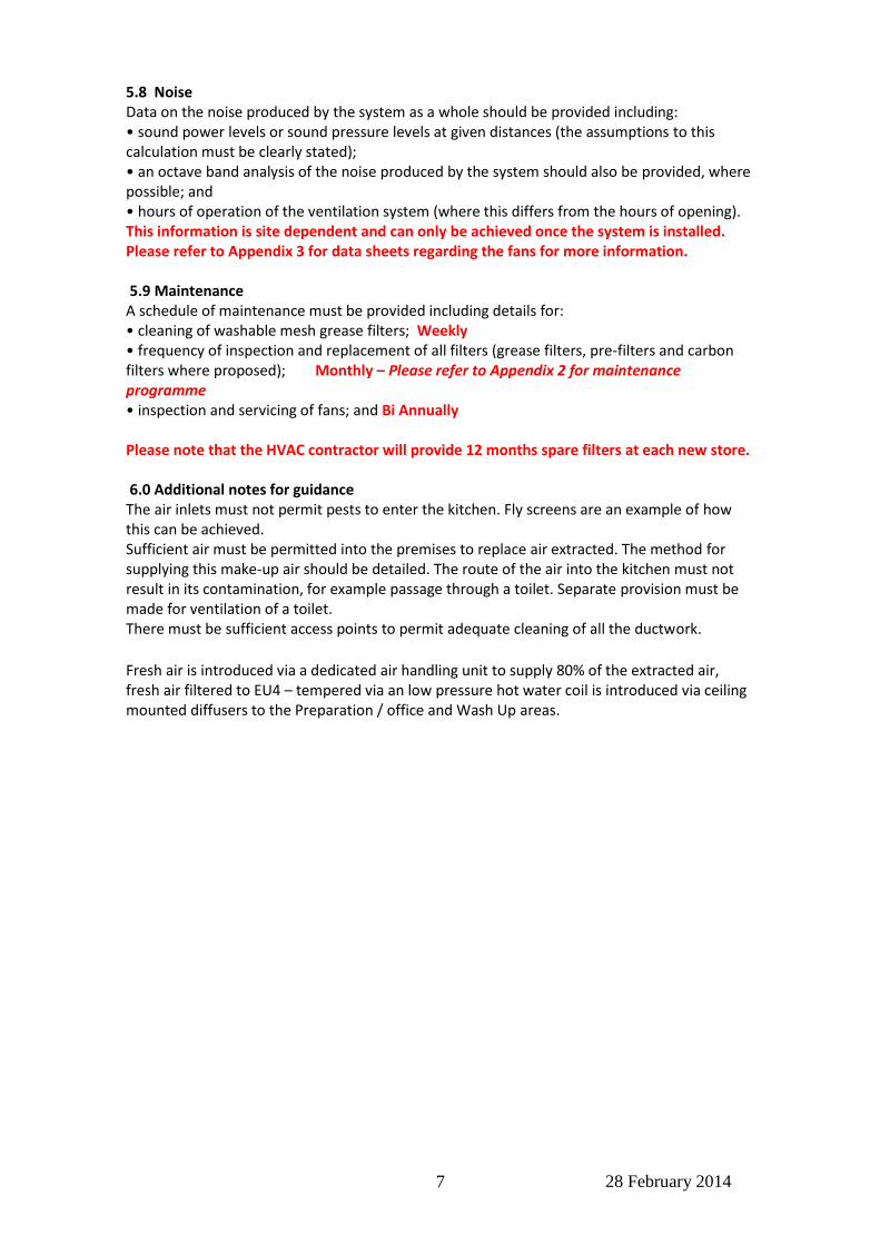
5.8 Noise Data on the noise produced by the system as a whole should be provided including: • sound power levels or sound pressure levels at given distances (the assumptions to this calculation must be clearly stated); • an octave band analysis of the noise produced by the system should also be provided, where possible; and • hours of operation of the ventilation system (where this differs from the hours of opening). This information is site dependent and can only be achieved once the system is installed. Please refer to Appendix 3 for data sheets regarding the fans for more information. 5.9 Maintenance A schedule of maintenance must be provided including details for: • cleaning of washable mesh grease filters; Weekly • frequency of inspection and replacement of all filters (grease filters, pre-filters and carbon filters where proposed); Monthly – Please refer to Appendix 2 for maintenance programme • inspection and servicing of fans; and Bi Annually Please note that the HVAC contractor will provide 12 months spare filters at each new store. 6.0 Additional notes for guidance The air inlets must not permit pests to enter the kitchen. Fly screens are an example of how this can be achieved. Sufficient air must be permitted into the premises to replace air extracted. The method for supplying this make-up air should be detailed. The route of the air into the kitchen must not result in its contamination, for example passage through a toilet. Separate provision must be made for ventilation of a toilet. There must be sufficient access points to permit adequate cleaning of all the ductwork.
Fresh air is introduced via a dedicated air handling unit to supply 80% of the extracted air, fresh air filtered to EU4 – tempered via an low pressure hot water coil is introduced via ceiling mounted diffusers to the Preparation / office and Wash Up areas.

28 February 2014 8
APPENDIX 1
COLDROOM AND AIR CONDITIONING COMPRESSORS
TYPICAL AIR CONDITIONING AND COLD ROOM COMPRESSOR DETAILS
AIR CONDITIONING COLD ROOM
Model (typical unit)
Mitsubishi H.I. FDC 100VNX
Model (typical unit)
Karbox 2464
Dimensions W 970mm D 350mm H 1300mm
Dimensions
W 890 D 560 H 500
Weight 105 kg Weight 78 kg
Airflow 1620 cu.m/h Compressor Model CAJ2464 34.5cm3 9.7 MRA 38 LRA
Current Start N/A Max running current 11.1A
Refrigerant Connections
Suction 15.9mm Liquid 9.5mm
Capacity Cool 10.0 kW Heat 11.2 kW
Condenser Fan Motor
220-1 Volts/Phase 0.6 Amps each
2800 m/hr Air Flow
Noise 50 dBA @ 1m Watts 4-6kW
Electrical Details 16 MRA 38 LRA
Noise 34dBA @ 10m

28 February 2014 9
APPENDIX 2
Additional Information on Carbon Filters and Maintenance Programme

28 February 2014 10
SUITE 1 SOHO STUDIOS
TOWN LANE
WOOBURN GREEN
BUCKINGHAMSHIRE
HP10 0PF
TELEPHONE: (07004) AIRCON
(01 628 536680)
FAX: (01628) 536681) E-mail: [email protected]
11th May 2005
Ref Carbon Filtration
Dear Sirs,
Re : Carbon Filter Installations
Further to your request for additional information regarding installations where the Local
Authority has requested the use of carbon filter.
Generally the installation of carbon filters is undertaken as follows, the fan selection is changed
to cater for the increased resistance given by the carbon filters, the area of carbon filter panels/
carbon weight has been calculated in conjunction with the supplier,
In general terms for each cu/m of air moved for a dwell time of 0.1 sec 46.9kg of carbon will be
required.
The configuration of the filter housing ensures a minimum dwell time of 0.1 sec to ensure the
necessary contact time with the vitiated air.
The carbon filter granules are bonded together and formed in to panels which are contained in
metal frames, a purpose made housing to contain the required number of panel has been
designed and the panel are installed to form as v section through the air must pass.
The recommended carbon grade that we use the Sutcliffe Carbon 207c
The life of the filter is dependant upon many factors use nature of air condition pre filtration is
essential to prolong the life of the carbon panel and we recommend these are changed bi
monthly.
The fan selection altered from a cased axial fan to an in line mixed flow to overcome the
additional resistance.
In general terms the above describes the carbon filter installation and specification of materials
employed.
Trust the above is satisfactory if you require additional information please contact the writer.
Yours faithfully,
M.Thorburn
28 February 2014 11
CARBON FILTER MAINTENANCE SCHEDULE
IT IS IMPORTANT THAT YOU MAINTAIN YOUR FUME EXTRACT SYSTEM
FOR THE FOLLOWING REASONS:
1. TO KEEP FLUE EMISSIONS TO A MINIMUM.
2. TO KEEP YOUR OVEN AND EXTRACT OPERABLE.
3. TO AVOID THE COSTLY REPLACEMENT OF THE CARBON
FILTER CELLS.
WARNING!
THE ACTIVATED CARBON FILTER CELL FILTRATION PACKAGE
FITTED TO THIS EXTRACT INSTALLATION HAS A PRE-FILTER WHICH
WILL ENSURE THAT GREASE AND SMOKE PARTICLES ARE
PREVENTED FROM REACHING THE MAIN CARBON FILTER. FAILURE
TO CARRY OUT THE FOLLOWING CHECKS WILL RESULT IN THE
PREMATURE DETERIORATION OF THE FILTERS AND COULD LEAD TO
PERMANENT DAMAGE TO THE FANS. THE INSTALLATION IS FITTED
WITH A GAS SAFETY CUT OFF VALVE WHICH IS DEPENDANT ON THE
DESIGNED AIRFLOW THROUGH THE SYSTEM. IF THE FILTER IS NOT
MAINTAINED THE GAS SUPPLY TO THE OVENS WILL BE SHUT OFF
DISABLING THE SYSTEM UNTIL THE FILTERS ARE REPLACED.
TO ENSURE YOUR BRANCH CAN OPERATE WITHOUT INTERUPTION IT
IS ESSENTIAL THAT THE FOLLOWING CHECKS ARE CARRIED OUT
EVERY 14 DAYS. CHECK THE PRE FILTERS TO ENSURE THAT NO GREASE BUILD UP OCCURS
REPLACE AS NECESSARY.
EVERY 3 MONTHS
CHECK THE MAIN FILTER BODY FOR A BUILD UP OF GREASE AND DUST
EVERY 12 MONTHS.
THE FILTERS ARE TO BE CHECKED BY A QUALIFIED HVAC ENGINEER A
REPORT ON THE FILTER CONDITION WILL BE ISSUED IN WRITING WITH
A RECOMMENDATION FOR REPLACEMENT OR CONTINUATION TO THE
NEXT SEVICE INTERVAL.

28 February 2014 12
APPENDIX 3
DATA SHEETS
o JASUN Filtration PLC – Model GF mesh Grease Filters – Canopy Filters o Jasun Filtration PLC – AC207 panel filter – Carbon Filters o Vent-Axia – Black Sabre Slim case sickle fans – Extract Fan o Air Vent Technology – Water heated air handling units – Fresh Air o Jasun Filtration PLC – Type 90 panel Filter - Fresh Air Intake