Embed Size (px)
Citation preview
Disseny d’un sistema de detecció de vehicles lents - Marc Massó
Annex C
Fitxes tècniques dels components del hardware
C.1. Bateria
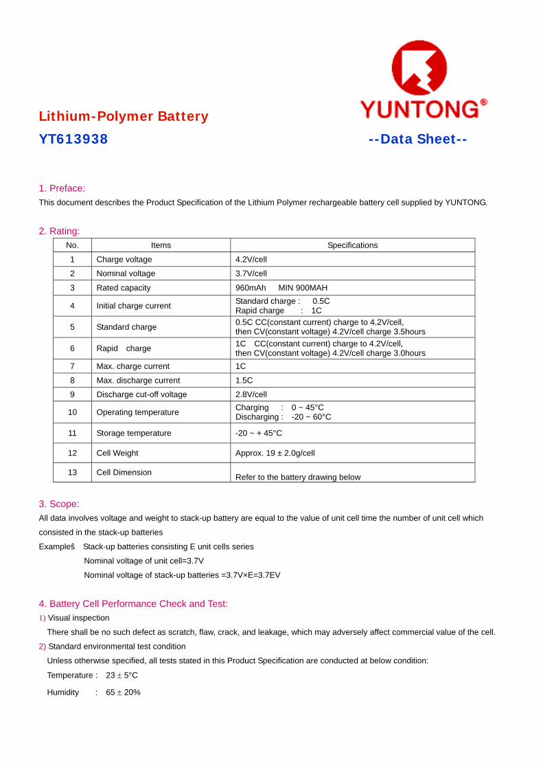
Lithium-Polymer Battery
YT613938 --Data Sheet-- 1. Preface:
This document describes the Product Specification of the Lithium Polymer rechargeable battery cell supplied by YUNTONG.
2. Rating:
No. Items Specifications
1 Charge voltage 4.2V/cell
2 Nominal voltage 3.7V/cell
3 Rated capacity 960mAh MIN 900MAH
4 Initial charge current Standard charge : 0.5C Rapid charge : 1C
5 Standard charge 0.5C CC(constant current) charge to 4.2V/cell, then CV(constant voltage) 4.2V/cell charge 3.5hours
6 Rapid charge 1C CC(constant current) charge to 4.2V/cell, then CV(constant voltage) 4.2V/cell charge 3.0hours
7 Max. charge current 1C
8 Max. discharge current 1.5C
9 Discharge cut-off voltage 2.8V/cell
10 Operating temperature Charging : 0 ~ 45°C Discharging : -20 ~ 60°C
11 Storage temperature -20 ~ + 45°C
12 Cell Weight Approx. 19 ± 2.0g/cell
13 Cell Dimension Refer to the battery drawing below
3. Scope: All data involves voltage and weight to stack-up battery are equal to the value of unit cell time the number of unit cell which
consisted in the stack-up batteries
Example: Stack-up batteries consisting E unit cells series
Nominal voltage of unit cell=3.7V
Nominal voltage of stack-up batteries =3.7V×E=3.7EV
4. Battery Cell Performance Check and Test: 1) Visual inspection
There shall be no such defect as scratch, flaw, crack, and leakage, which may adversely affect commercial value of the cell.
2) Standard environmental test condition
Unless otherwise specified, all tests stated in this Product Specification are conducted at below condition:
Temperature : 23 ± 5°C
Humidity : 65 ± 20%
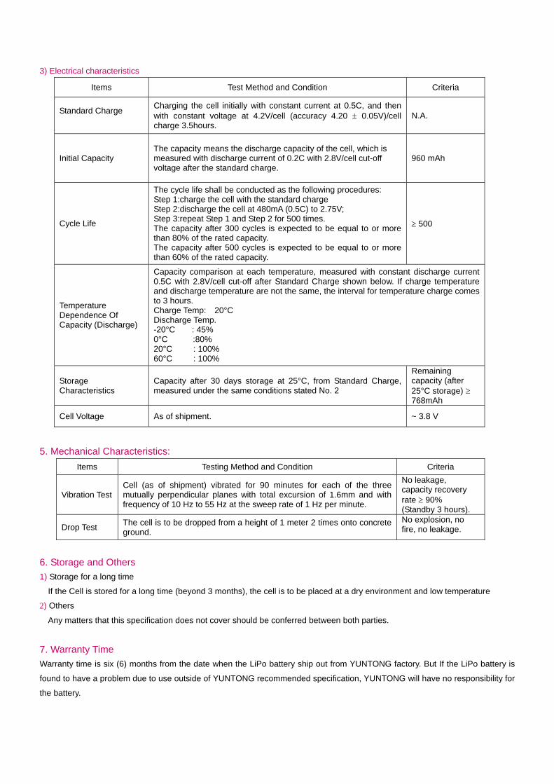
3) Electrical characteristics
Items Test Method and Condition Criteria
Standard Charge
Charging the cell initially with constant current at 0.5C, and then with constant voltage at 4.2V/cell (accuracy 4.20 ± 0.05V)/cell charge 3.5hours.
N.A.
Initial Capacity
The capacity means the discharge capacity of the cell, which is measured with discharge current of 0.2C with 2.8V/cell cut-off voltage after the standard charge.
960 mAh
Cycle Life
The cycle life shall be conducted as the following procedures: Step 1:charge the cell with the standard charge Step 2:discharge the cell at 480mA (0.5C) to 2.75V; Step 3:repeat Step 1 and Step 2 for 500 times. The capacity after 300 cycles is expected to be equal to or more than 80% of the rated capacity. The capacity after 500 cycles is expected to be equal to or more than 60% of the rated capacity.
≥ 500
Temperature Dependence Of Capacity (Discharge)
Capacity comparison at each temperature, measured with constant discharge current 0.5C with 2.8V/cell cut-off after Standard Charge shown below. If charge temperature and discharge temperature are not the same, the interval for temperature charge comes to 3 hours. Charge Temp: 20°C Discharge Temp. -20°C : 45% 0°C :80% 20°C : 100% 60°C : 100%
Storage Characteristics
Capacity after 30 days storage at 25°C, from Standard Charge, measured under the same conditions stated No. 2
Remaining capacity (after 25°C storage) ≥ 768mAh
Cell Voltage As of shipment. ~ 3.8 V
5. Mechanical Characteristics: Items Testing Method and Condition Criteria
Vibration Test Cell (as of shipment) vibrated for 90 minutes for each of the three mutually perpendicular planes with total excursion of 1.6mm and with frequency of 10 Hz to 55 Hz at the sweep rate of 1 Hz per minute.
No leakage, capacity recovery rate ≥ 90% (Standby 3 hours).
Drop Test The cell is to be dropped from a height of 1 meter 2 times onto concrete ground.
No explosion, no fire, no leakage.
6. Storage and Others 1) Storage for a long time
If the Cell is stored for a long time (beyond 3 months), the cell is to be placed at a dry environment and low temperature
2) Others Any matters that this specification does not cover should be conferred between both parties.
7. Warranty Time Warranty time is six (6) months from the date when the LiPo battery ship out from YUNTONG factory. But If the LiPo battery is
found to have a problem due to use outside of YUNTONG recommended specification, YUNTONG will have no responsibility for
the battery.
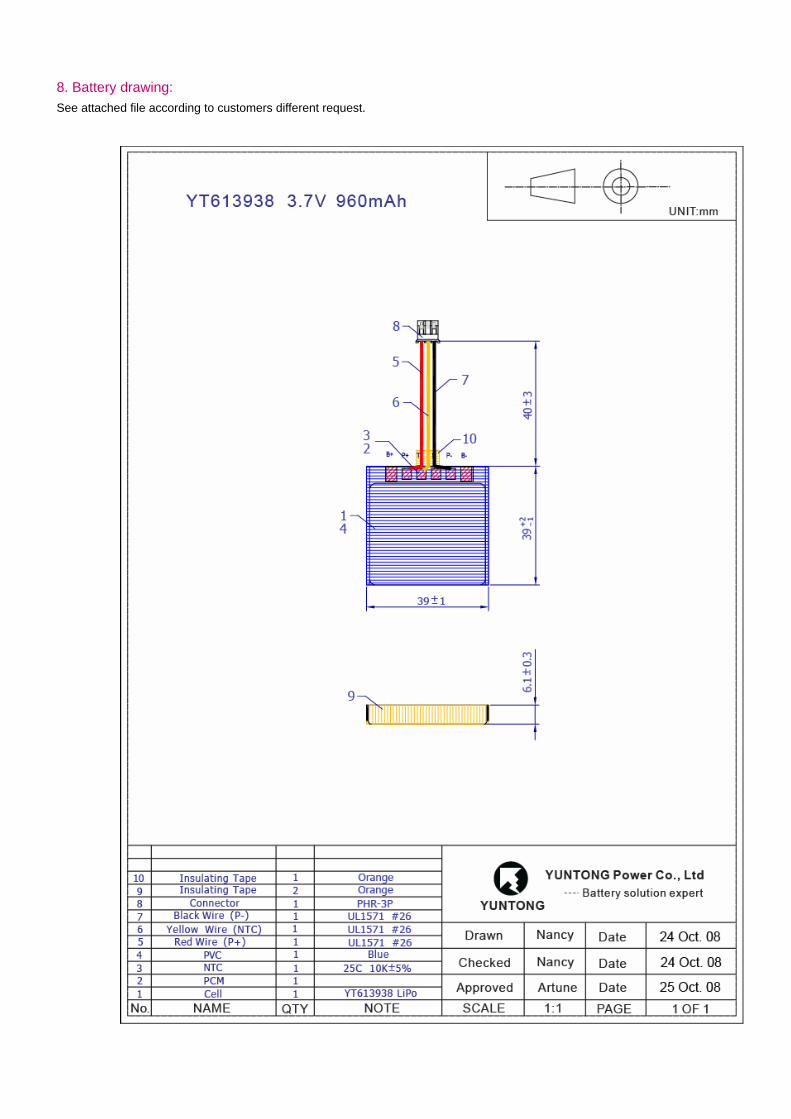
8. Battery drawing: See attached file according to customers different request.
Handling Precautions and Guideline For LIP (Lithium-Ion Polymer) Rechargeable Batteries
Subject to change without notice Preface This document of 'Handling Precautions and Guideline LIP Rechargeable Batteries' shall be applied to the battery cells
manufactured by YUNTONG POWER CO.LTD.
Note (1):
The customer is requested to contact YUNTONG in advance, if and when the customer needs other applications or operating
conditions than those described in this document. Additional experimentation may be required to verify performance and safety
under such conditions.
Note (2):
YUNTONG will take no responsibility for any accident when the cell is used under other conditions than those described in this
Document.
Note (3):
YUNTONG will inform, in a written form, the customer of improvement(s) regarding proper use and handling of the cell, if it is
deemed necessary.
1. Charging
1) Charging current:
Charging current should be less than maximum charge current specified in the Product Specification. Charging with higher
current than recommended value may cause damage to cell electrical, mechanical, and safety performance and could lead to
heat generation or leakage.
2) Charging voltage:
Charging shall be done by voltage less than that specified in the Product Specification (4.2V/cell). Charging beyond 4.25V,
which is the absolute maximum voltage, must be strictly prohibited. The charger shall be designed to comply to this
condition. It is very dangerous that charging with higher voltage than specified value may cause damage to the cell electrical,
mechanical safety performance and could lead to heat generation or leakage.
3) Charging temperature:
The cell shall be charged within the specified temperature range in the Product Specification.
4) Prohibition of reverse charging:
Reverse charging is prohibited. The cell shall be connected correctly. The polarity has to be confirmed before wiring. In case
of the cell is connected improperly, the cell cannot be charged. Simultaneously, the reverse charging may cause damaging
to the cell which may lead to degradation of cell performance and damage the cell safety, and could cause heat generation or
leakage.
2. Discharging
1) Discharging current
The cell shall be discharged at less than the maximum discharge current specified in the Product Specification. High
discharging current may reduce the discharging capacity significantly or cause over-heat.
2) Discharging temperature
The cell shall be discharged within the temperature range specified in the Product Specification.
3) Over-discharging:
It should be noted that the cell would be at an over-discharged state by its self-discharge characteristics in case the cell is not
used for long time. In order to prevent over-discharging, the cell shall be charged periodically to maintain between 3.7V and
3.9V. Over-discharging may causes loss of cell performance, characteristics, or battery functions.
The charger shall be equipped with a device to prevent further discharging exceeding a cut-off voyage specified in the
Product Specification. Also the charger shall be equipped with a device to control the recharging.
Procedures as follows:
The cell battery pack shall start with a low current (0.01C) for 15 - 30 minutes, i.e. pre-charging, before rapid charging starts.
The rapid charging shall be started after the individual cell voltage has been reached above 3V within 15 - 30 minutes which
can be determined with the use of an appropriate timer for pre-charging. In case the individual cell voltage does not rise to 3V
within the pre-charging time, then the charger shall have functions to stop further charging and display the cell/pack is at
abnormal state.
3. Protection Circuit Module (PCM)
1) The cell/battery pack shall be with a PCM which can protect cell/battery pack properly.
PCM shall have functions of (i) overcharging prevention, (ii) over-discharging prevention, (iii) over current prevention to
maintain safety and prevent significant deterioration of cell performance. The over current can occur by external short circuit.
2) Overcharging prohibition:
Overcharging prevention function shall stop charging if any one of the cells of the battery pack reaches 4.25V.
3) Over-discharge prohibition:
Over-discharging prevention function shall work to minimize a dissipation current to avoid further drop in cell voltage of 2.5V
or less per cell in any cell of the battery pack. It is recommended that the dissipation current of PCM shall be minimized to
0.5uA or less with the over-discharge prevention. The protection function shall monitor each bank of the battery pack and
control the current all the time.
4. Storage
The cell should be stored within the proper temperature range specified in the Product Specification.
5. Handling of Cells
1) Consideration of strength of film package
(i)Aluminium laminated film. (ii) Easily damaged by sharp edge parts such as pins and needles, comparing with
metal-can-cased LIB. (iii)Sealed edge May be damaged by heat above 100°C.
2) Prohibition short circuit
Never make short circuit cell. It generates very high current which causes heating of the cells and may cause electrolyte
leakage, gassing or explosion that are very dangerous. The LIP tabs may be easily short-circuited by putting them on
conductive surface. (Such outer short circuit may lead to heat generation and damage of the cell.) An appropriate circuitry
with PCM shall be employed to protect accidental short circuit of the battery pack.
3) Mechanical shock
LIP cells have less mechanical endurance than metal-can-cased LIB.
Falling, hitting, bending, etc. may cause degradation of LIP characteristics.
4) Handling of tabs
The LIP tabs are not exceedingly sturdy, especially the aluminium tabs for the terminal. Do not put much force on LIP tabs.
(Aluminium tab may easily be torn off by shear force.) Do not bend tabs unnecessarily.
6. Notice for Designing Battery Pack
1) Pack toughness
Battery pack should have sufficient strength and the LIP cell inside should be protected from mechanical shocks.
2) Cell fixing
The LIP cell should be fixed to the battery pack by its large surface area.
No cell movement in the battery pack should be allowed.
3) Inside design
No sharp edge components should be inside the pack containing the LIP cell.
4) Tab connection
Ultrasonic welding is recommended for LIP tab connection method.
Battery pack should be designed that shear force are not applied to the LIP tabs.
5) For mishaps
Battery pack should be designed not to generate heat even when leakage occurs due to mishaps.
i) Isolate PCM (Protection Circuit Module) from leaked electrolyte as perfectly as possible.
ii) Avoid narrow spacing between bare circuit patterns with different voltage. (Including around connector).
iii) LIP battery should not have liquid from electrolyte, but in case If leaked electrolyte touches bare circuit patterns, higher
potential terminal material may dissolve and precipitate at the lower potential terminal, and may cause short circuit. The
design of the PCM must have this covered.
7. Notice for Assembling Battery Pack
Shocks, high temperature, or contacts of sharp edge components should not be allowed in battery pack assembling process.
1) Do not solder directly to LIP tabs. Do not bring heated tools such as soldering Iron close to LIP cells. Temperature above
80°C may cause damage to the LIP cell and degrade its performances.
2) In case that the battery pack is fixed by ultrasonic welding, it is necessary not to apply too much ultrasonic welding power to
LIP cell and electronic circuits such as PCM. Otherwise it may cause serious damage to the cells and electronic circuit.
8. Others
1) Cell connection
i) Direct soldering of wire leads or devices to the cell is strictly prohibited.
ii) Lead tabs with pre-soldered wiring shall be spot welded to the cells. Direct soldering may cause damage of components, such
as separator and insulator, by heat generation.
2) Prevention of short circuit within a battery pack
Enough insulation layers between wiring and the cells shall be used to maintain extra safety protection. The battery pack shall
be structured with no short circuit within the battery pack, which may cause generation of smoke or firing.
3) Prohibition of disassembly
i) Never disassemble the cells
The disassembling may generate internal short circuit in the cell, which may cause gassing, fining, explosion, or other
problems.
ii) Electrolyte is harmful
LIP battery should not have liquid from electrolyte flowing, but in case the electrolyte come into contact with the skin, or eyes,
physicians shall flush the electrolyte immediately with fresh water and medical advice is to be sought.
4) Prohibition of dumping of cells into fire
Never incinerate nor dispose the cells in fire. These may cause explosion of the cells, which is very dangerous and is
prohibited.
5) Prohibition of cells immersion into liquid such as water
The cells shall never be soaked with liquids such as water, seawater, drinks such as soft drinks, juices, coffee or others.
6) Battery cells replacement
The battery replacement shall be done only by either cells supplier or device supplier and never be done by the user.
7) Prohibition of use of damaged cells
The cells might be damaged during shipping by shock. If any abnormal features of the cells are found such as damages in a
plastic envelop of the cell, deformation of the cell package, smelling of an electrolyte, an electrolyte leakage and others, the
cells shall never be used any more.
The Cells with a smell of the electrolyte or a leakage shall be placed away from fire to avoid firing or explosion.

PCM:
1. Scope
This specification shall be applied to Lithium ion polymer battery protection circuit module- model number PCM 318B 3.0V
manufactured by YUNTONG. 2. Type and Model
2.1 Type: Protection Module for Li Ion/Li-Polymer Battery Pack
2.2 Model: PCM 318B 3.0V
3. Absolute Maximum Ratings
3.1 Supply Voltage: -0.3V to 12 V
3.2. Operating Temperature: -40oC to 85oC
3.3 Storage Temperature: -55oC to125oC
4. Electrical Characteristics (25oC)
The followings is referring to the specs of S-8261G3J or R5402N163KD (Rev 1.2) of Seiko (for details, see S-8261specs or
R5402N163KD). These specs are guaranteed by design not by production tests.
4.1 Input Voltage (VDD vs Vss): 1.5V(min) 8.0V(max) For S-8261G3J
1.5V (min) 5.0V(max) For R5402N163KD
4.2 Overcharge Detection :4.255V (min) 4.280V(Typ) 4.305V(max) For S-8261G3J or R5402N163KD
4.3 Released voltage from Over-charge: 4.03V(min) 4.08V(Typ) 4.13V(max) For S-8261G3J
4.05V(min) 4.10V(Typ) 4.15V(max) For R5402N163KD
4.4 Output Delay of Overcharge: 1.0s (min) 1.2s (Typ.) 1.4s (max) For S-8261G3J
0.7s (min) 1.0s (Typ.) 1.3s (max) For R5402N163KD
4.5 Over-discharge Detection: 2.95V (min) 3.0V(Typ) 3.05V(max) For S-8261G3J
2.925V (min) 3.0V(Typ) 3.075V(max) For R5402N163KD
4.6 Released voltage from Over-discharge: -(min) 3.0V(Typ) 3.1V(max) For S-8261G3J
3.12V(min) 3.2V(Typ) 3.28V(max) For R5402N163KD
4.7 Output Delay of Over-discharge: 115ms (min) 144ms(Typ.) 173ms (max) For S-8261G3J
14ms (min) 20ms(Typ.) 26ms (max) For R5402N163KD
4.8 Over Current Detection: 0. 065V (min) 0.08V(Typ) 0.095V(max) For S-8261G3J
0. 085V (min) 0.1V(Typ) 0.115V(max) For R5402N163KD
4.9Output Delay of Over-Current: 7ms (min) 9ms(Typ.) 11ms (max) For S-8261G3J
8ms (min) 12ms(Typ.) 16ms (max) For R5402N163KD
4.10 Load Short Detection Voltage: 0.7V 1.2V 1.7V For S-8261G3J
0.55V 0.8V 1.0V For R5402N163KD
4.11 Output Delay of Short Protection: 220µs (min) 320 µs(Typ.) 380µs (max) For S-8261G3J
230µs (min) 300 µs(Typ.) 500µs (max) For R5402N163KD
4.12 Current Consumption (active status): 3.5µA (Typ) 7.0µA (max) For S-8261G3J
4.0µA (Typ) 8.0µA (max) For R5402N163KD
4.13 Current Consumption (Standby): -µA (Typ) 0.1µA (max) For S-8261G3J
1.2µA (Typ) 2.0µA (max) For R5402N163KD
4.14 PCM Resistance : 35mΩ(min) 50mΩ(Typ) 60mΩ(max) For S-8261G3J or R5402N163KD
5. Remarks
Any other items which are not covered in this specification shall be agreed by both parties
p+
p-
S
C1
U1
U1
1
2
3
4
5
6
DO
UT
V-
CO
UT
CT VD
D
VSS
BATTERY
R1
U2
R3R2
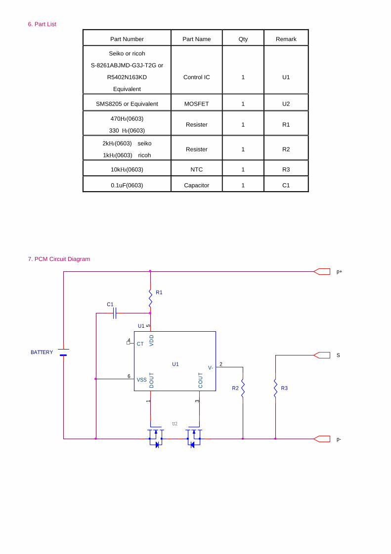
6. Part List
Part Number Part Name Qty Remark
Seiko or ricoh
S-8261ABJMD-G3J-T2G or
R5402N163KD
Equivalent
Control IC
1
U1
SMS8205 or Equivalent MOSFET 1 U2
470Ω(0603)
330 Ω(0603) Resister 1 R1
2kΩ(0603) seiko
1kΩ(0603) ricoh Resister 1 R2
10kΩ(0603) NTC 1 R3
0.1uF(0603) Capacitor 1 C1
7. PCM Circuit Diagram

8. PCM Lay out
Note:
This document is limited and controlled by YUNTONG, and property right is belong to YUNTONG. Do not copy and
send to the third part without YUNTONG permitted. Even do not asking thirty party to do according to the above data
without YUNTONG permitted. Otherwise will responsibility of laws.
YUNTONG Group Limited (HK company) YUNTONG Power Co.,Ltd. Tel: 86-760 88299191, 88299192, 88299193 Fax:86-760 88299581 Email: [email protected] www.yuntong-batt.com
Disseny d’un sistema de detecció de vehicles lents - Marc Massó
C.2. Led
SPEC NO: DSAC0451 REV NO: V.5 DATE: MAR/29/2005 PAGE: 1 OF 3
APPROVED: J. Lu CHECKED: Allen Liu DRAWN: S.H.CHEN
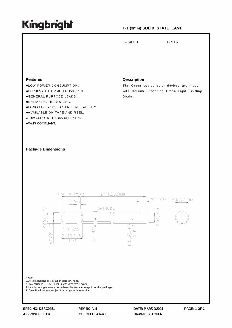
Package Dimensions
L-934LGD GREEN
Description
The Green source color devices are made
with Gallium Phosphide Green Light Emitt ing
Diode.
T-1 (3mm) SOLID STATE LAMP
Features
zLOW POWER CONSUMPTION.
zPOPULAR T-1 DIAMETER PACKAGE.
zGENERAL PURPOSE LEADS
zRELIABLE AND RUGGED.
zLONG LIFE - SOLID STATE RELIABILITY.
zAVAILABLE ON TAPE AND REEL.
zLOW CURRENT IF=2mA OPERATING.
zRoHS COMPLIANT.
Notes:1. All dimensions are in millimeters (inches).2. Tolerance is ±0.25(0.01") unless otherwise noted.3. Lead spacing is measured where the leads emerge from the package.4. Specifications are subject to change without notice.

SPEC NO: DSAC0451 REV NO: V.5 DATE: MAR/29/2005 PAGE: 2 OF 3
APPROVED: J. Lu CHECKED: Allen Liu DRAWN: S.H.CHEN
Selection Guide
Note:1. θ1/2 is the angle from optical centerline where the luminous intensity is 1/2 the optical centerline value.
Part No. Dice Lens Type
Iv (mcd) @ 2mA
Viewing Angle
Min. Typ. 2θ1/2
L-934LGD GREEN (GaP) GREEN DIFFUSED 0.7 2 60°
Electrical / Optical Characteristics at TA=25°C
Symbol Parameter Device Typ. Max. Test ConditionsUnits
λpeak Peak Wavelength Green 565 nm IF=20mA
λD Dominant Wavelength Green 568 nm IF=20mA
∆λ1/2 Spectral Line Half-width Green 30 nm IF=20mA
C Capacitance Green 15 pF VF=0V;f=1MHz
VF Forward Voltage Green 2.2 2.5 V IF=20mA
IR Reverse Current Green 10 uA VR = 5V
Absolute Maximum Ratings at TA=25°C
Notes:1. 1/10 Duty Cycle, 0.1ms Pulse Width.2. 2mm below package base.3. 5mm below package base.
Parameter Green Units
Power dissipation 105 mW
DC Forward Current 25 mA
Peak Forward Current [1] 140 mA
Reverse Voltage 5 V
Operating/Storage Temperature -40°C To +85°C
Lead Solder Temperature [2] 260°C For 3 Seconds
Lead Solder Temperature [3] 260°C For 5 Seconds
SPEC NO: DSAC0451 REV NO: V.5 DATE: MAR/29/2005 PAGE: 3 OF 3
APPROVED: J. Lu CHECKED: Allen Liu DRAWN: S.H.CHEN
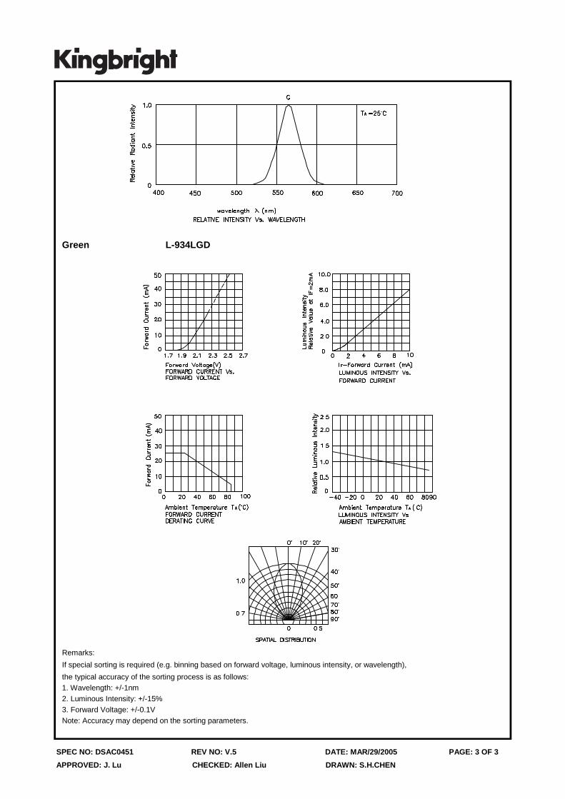
Green L-934LGD
Remarks:
If special sorting is required (e.g. binning based on forward voltage, luminous intensity, or wavelength),
the typical accuracy of the sorting process is as follows:1. Wavelength: +/-1nm2. Luminous Intensity: +/-15%3. Forward Voltage: +/-0.1VNote: Accuracy may depend on the sorting parameters.
Disseny d’un sistema de detecció de vehicles lents - Marc Massó
C.3. Interruptor
Disseny d’un sistema de detecció de vehicles lents - Marc Massó
C.4. Antena
Esta antena para montaje externo, roscada a chapa, es ideal para aplicarla con
equipos localizadores/terminales que necesiten combinar en un pequeño espacio y
mejorando la recepción de las señales, la antena GSM y la GPS. De tamaño muy
reducido es ideal para pequeños objetos.
-Antena GSM/GPRS doble banda 900-1800Mhz.
-Ganancia GSM 0dBi
-Ganancia GPS 27 dBi
-Alimentacion antena GPS: 3.3 - 5V extendida
-Cable 5 metros.
-Diferentes posibilidades de conectores. Consultenos. Por defecto se envia
CONECTOR GPS: SMA M
CONECTOR GSM: FME F
Informació extreta de:
http://www.coelvi.es/shop/es/antenas-gps/428-antena-dual-gsm-gps-shark.html

Disseny d’un sistema de detecció de vehicles lents - Marc Massó
C.5. Mòdul conjunt
1
GR2 – GSM/GPRS + GPS Modem Product description Rev. 1 – 21/06/2012
Contents 1. Overview.............................................................................................................................................. 2
1.1 Mechanical Outline ....................................................................................................................... 3
1.2 Part Numbers ................................................................................................................................ 3
2 Hardware Interface Description ........................................................................................................... 4
2.1 Main features of the GR2 .............................................................................................................. 4
2.2 GR2 Power Supply block diagram ................................................................................................. 5
2.3 Interface Description ..................................................................................................................... 6
2.3.1 IO interface ............................................................................................................................. 6
2.3.2 Power supply .......................................................................................................................... 7
2.3.3 Supply Voltage Requirements ................................................................................................ 8
2.3.4 RS-232 interface ..................................................................................................................... 9
2.3.5 Battery Management ............................................................................................................. 9
2.3.6 External Battery ...................................................................................................................... 9
2.3.7 ADDITIONAL GPS PIN ACCESS ............................................................................................... 10
2.4 Antenna Requirements ............................................................................................................... 10
2.4.1 Internal Mount Options ........................................................................................................ 10
3 Limited Warranty................................................................................................................................ 12

2
1. Overview
The GR2 is a board based on the Telit GE864-GPS module for GPRS GPS Applications The Unit includes:
• Quad Band GSM/GPRS Modem • The latest SiRF Star IV GPS engine • In built Python script engine so that scripts can be run directly on the GE864-GPS Module • Wide range Power supply 5-55V • On board SIM Holder. • On board charger circuit and connector for LiPO battery connection • Either RS232 or UART connection
Note: Picture shown with RS232 interface

3
1.1 Mechanical Outline
Figure 1 – Mechanical Outline
1.2 Part Numbers GR2-RS232 – with RS232 interface fitted GR2-UART – with UART interface fitted
4
2 Hardware Interface Description
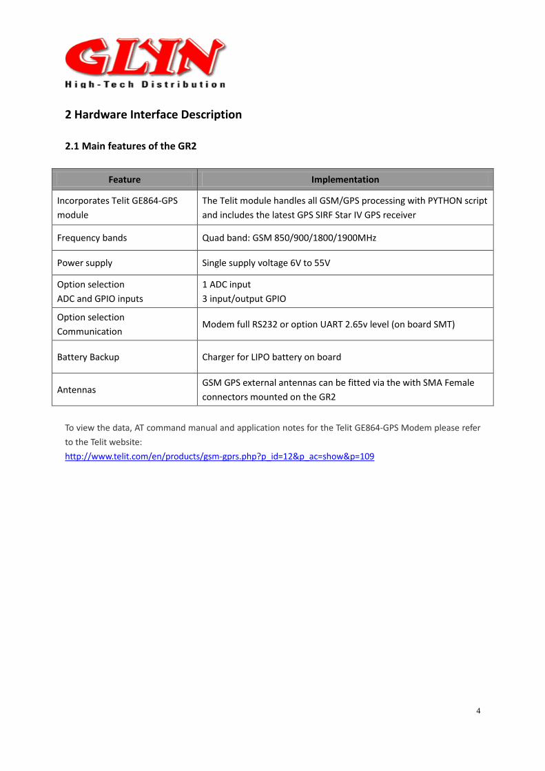
2.1 Main features of the GR2
Feature Implementation
Incorporates Telit GE864-GPS module
The Telit module handles all GSM/GPS processing with PYTHON script and includes the latest GPS SIRF Star IV GPS receiver
Frequency bands Quad band: GSM 850/900/1800/1900MHz
Power supply Single supply voltage 6V to 55V
Option selection ADC and GPIO inputs
1 ADC input 3 input/output GPIO
Option selection Communication
Modem full RS232 or option UART 2.65v level (on board SMT)
Battery Backup Charger for LIPO battery on board
Antennas GSM GPS external antennas can be fitted via the with SMA Female connectors mounted on the GR2
To view the data, AT command manual and application notes for the Telit GE864-GPS Modem please refer to the Telit website: http://www.telit.com/en/products/gsm-gprs.php?p_id=12&p_ac=show&p=109
5
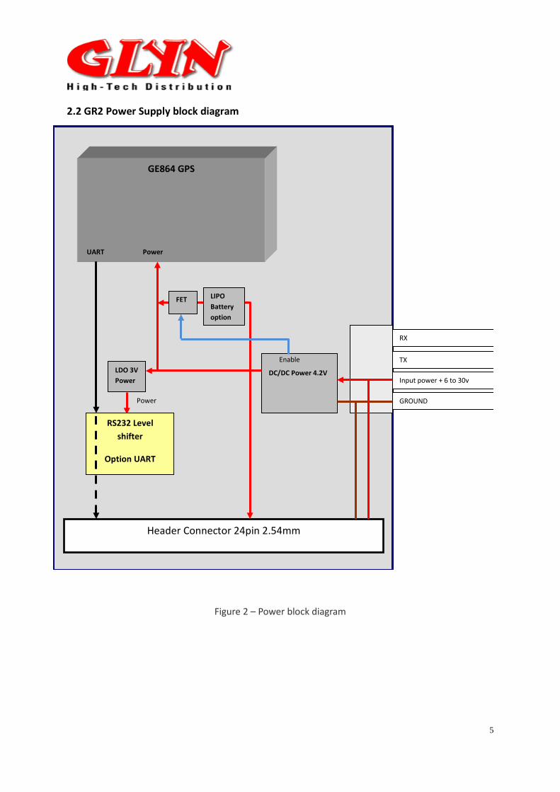
2.2 GR2 Power Supply block diagram
Input power + 6 to 30v
GROUND
GE864 GPS
Power
DC/DC Power 4.2V
RS232 Level
shifter
Option UART
Enable
Power
LDO 3V Power
FET LIPO Battery option
Header Connector 24pin 2.54mm
UART
TX
RX
Figure 2 – Power block diagram
6
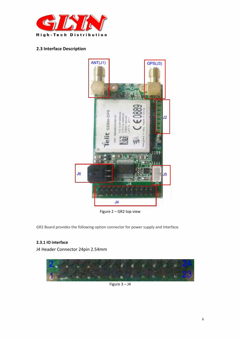
2.3 Interface Description
Figure 2 – GR2 top view
GR2 Board provides the following option connector for power supply and Interface.
2.3.1 IO interface
J4 Header Connector 24pin 2.54mm
Figure 3 – J4
7
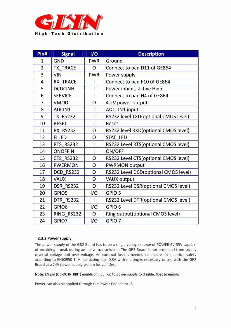
Pin# Signal I/O Description 1 GND PWR Ground 2 TX_TRACE O Connect to pad D11 of GE864 3 VIN PWR Power supply 4 RX_TRACE I Connect to pad F10 of GE864 5 DCDCINH I Power inhibit, active High 6 SERVICE I Connect to pad H4 of GE864 7 VMOD O 4.2V power output 8 ADCIN1 I ADC_IN1 input 9 TX_RS232 I RS232 level TXD(optional CMOS level)
10 RESET I Reset 11 RX_RS232 O RS232 level RXD(optional CMOS level) 12 FLLED O STAT_LED 13 RTS_RS232 I RS232 Level RTS(optional CMOS level) 14 ONOFFIN I ON/OFF 15 CTS_RS232 O RS232 Level CTS(optional CMOS level) 16 PWERMON O PWRMON output 17 DCD_RS232 O RS232 Level DCD(optional CMOS level) 18 VAUX O VAUX output 19 DSR_RS232 O RS232 Level DSR(optional CMOS level) 20 GPIO5 I/O GPIO 5 21 DTR_RS232 I RS232 Level DTR(optional CMOS level) 22 GPIO6 I/O GPIO 6 23 RING_RS232 O Ring output(optional CMOS level) 24 GPIO7 I/O GPIO 7
2.3.2 Power supply The power supply of the GR2 Board has to be a single voltage source of POWER 6V-55V capable of providing a peak during an active transmission. The GR2 Board is not protected from supply reversal voltage and over voltage. An external fuse is needed to ensure an electrical safety according to EN60950-1. A fast acting fuse 0.8A with melting is necessary to use with the GR2 Board at a 24V power supply system for vehicles. Note: EN pin (DC-DC INHIBIT) enable pin, pull up to power supply to disable, float to enable. Power can also be applied through the Power Connector J6 .

8
J6 – for Power connection – TOP VIEW
We also offer the mating power cable with flying leads that you can wire into any suitable power supply that is available in your setup. Details can be found at http://www.glynstore.com/products/EZ%252dPOWERCABLE-for-EZ10%7B47%7DEZ863%7B47%7DEZ864.html
2.3.3 Supply Voltage Requirements The DC power supply must be connected to the POWER input: • Input voltage range 6 - 55V DC • Nominal Voltage 12V DC • Power Supply current rating: max. 2A @12V • Power Supply ripple: max. 120mV • Input current in idle mode: 20mA @ 12V • Input average current in communication mode: 100mA @ 12V
Pin assignment 1 – Power (Bottom Right) 2 – RX-RS232 (Bottom Left) 3 – GND (Top Right) 4 – TX RS232 (Top Left)
9
2.3.4 RS-232 interface The serial interface of the GR2 is intended for the communication between the GSM module and the host application. This RS-232 interface is a data and control interface for transmitting data, AT commands and providing multiplexed channels. EMC immunity complies with the vehicular environment requirements according to EN 301 489-7. The user interface of the GR2 Terminal is accessible from a Data Terminal Equipment DTE connected to the RS232 interface and it is managed by AT commands according to the GSM 07.07 and 07.05 specification and the supported commands are listed in the AT Commands Reference Guide. Connector type on the terminal is: • Baud rate from 300 to 230,400 bit/s • Short circuit (to Ground) protection on all outputs. • Input voltage range: -12V to +12V
2.3.5 Battery Management The GR2 Board has internal LIPO BATTERY CHARGER LIPO BATTERY has NTC sensor, this sensor will not charge the battery when Temperature is out of the range of 0º to 45º
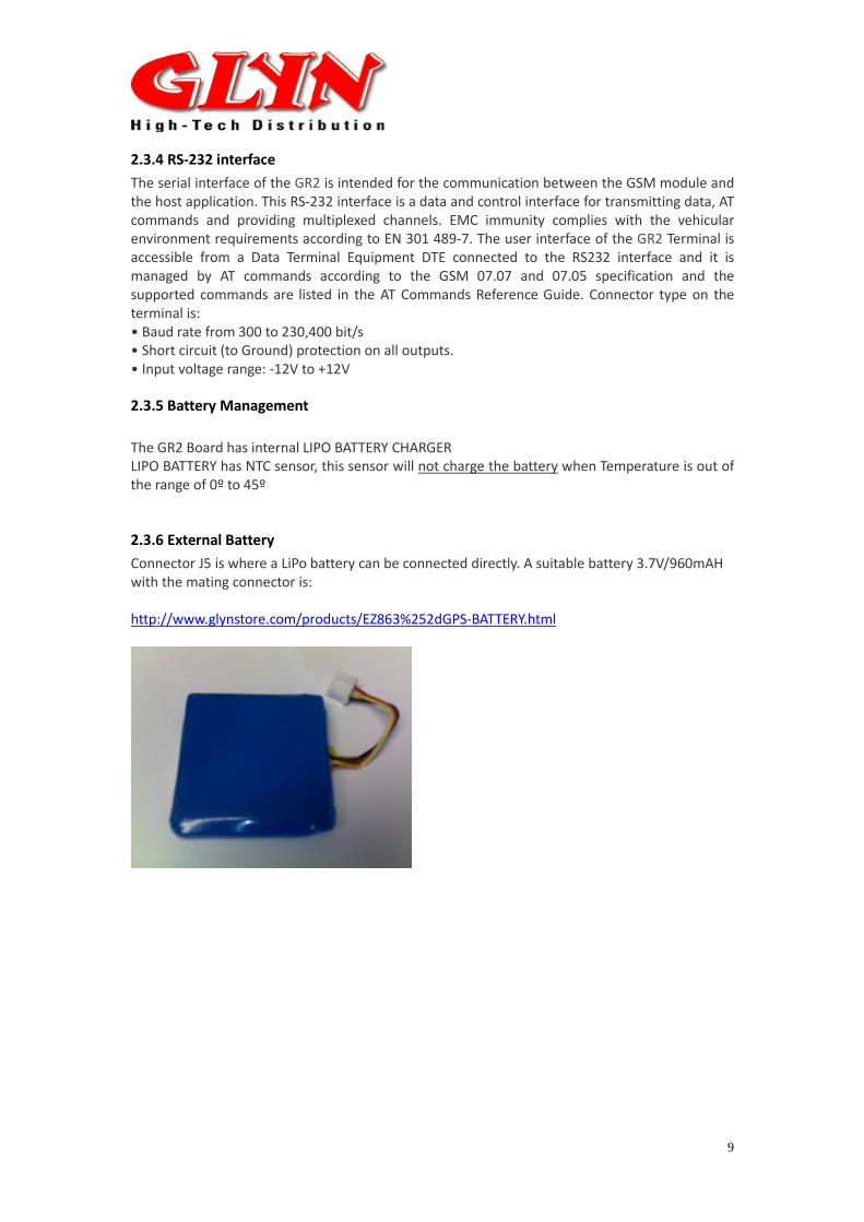
2.3.6 External Battery Connector J5 is where a LiPo battery can be connected directly. A suitable battery 3.7V/960mAH with the mating connector is: http://www.glynstore.com/products/EZ863%252dGPS-BATTERY.html
10
2.3.7 ADDITIONAL GPS PIN ACCESS
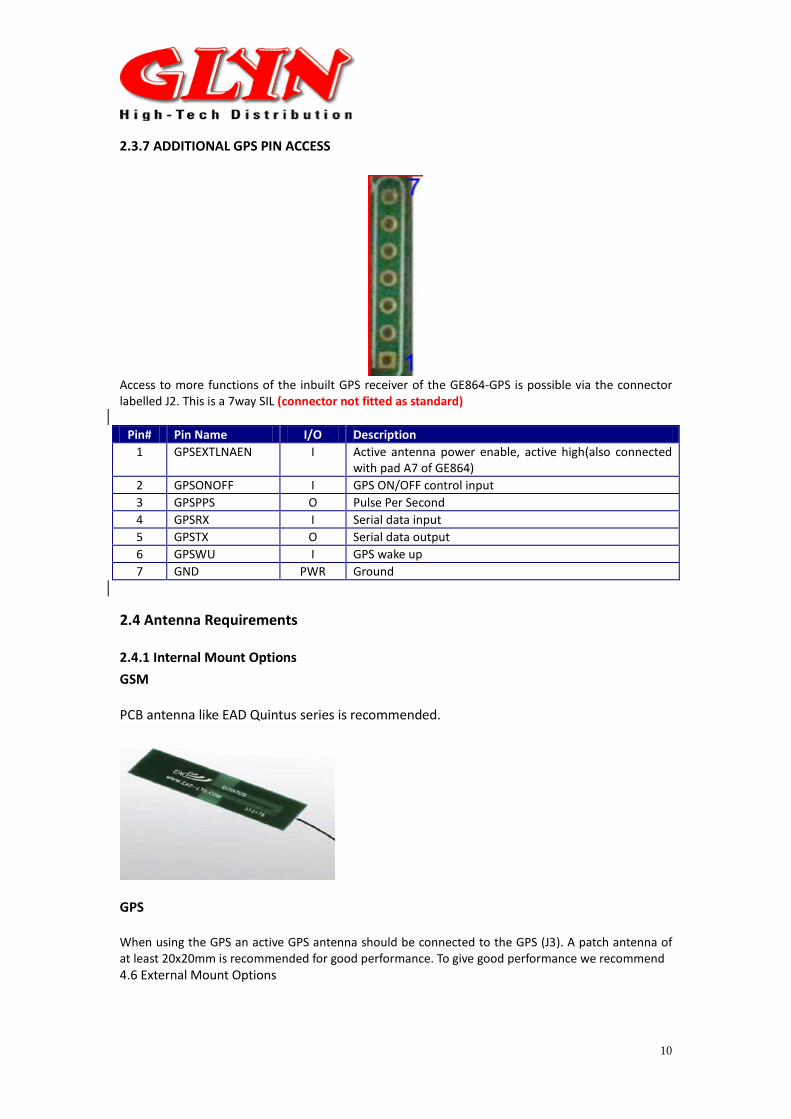
Access to more functions of the inbuilt GPS receiver of the GE864-GPS is possible via the connector labelled J2. This is a 7way SIL (connector not fitted as standard)
Pin# Pin Name I/O Description 1 GPSEXTLNAEN I Active antenna power enable, active high(also connected
with pad A7 of GE864) 2 GPSONOFF I GPS ON/OFF control input 3 GPSPPS O Pulse Per Second 4 GPSRX I Serial data input 5 GPSTX O Serial data output 6 GPSWU I GPS wake up 7 GND PWR Ground
2.4 Antenna Requirements
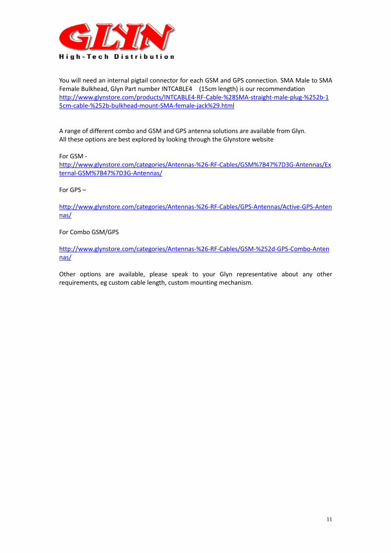
2.4.1 Internal Mount Options GSM PCB antenna like EAD Quintus series is recommended.
GPS When using the GPS an active GPS antenna should be connected to the GPS (J3). A patch antenna of at least 20x20mm is recommended for good performance. To give good performance we recommend 4.6 External Mount Options
11
You will need an internal pigtail connector for each GSM and GPS connection. SMA Male to SMA Female Bulkhead, Glyn Part number INTCABLE4 (15cm length) is our recommendation http://www.glynstore.com/products/INTCABLE4-RF-Cable-%28SMA-straight-male-plug-%252b-15cm-cable-%252b-bulkhead-mount-SMA-female-jack%29.html A range of different combo and GSM and GPS antenna solutions are available from Glyn. All these options are best explored by looking through the Glynstore website For GSM - http://www.glynstore.com/categories/Antennas-%26-RF-Cables/GSM%7B47%7D3G-Antennas/External-GSM%7B47%7D3G-Antennas/ For GPS – http://www.glynstore.com/categories/Antennas-%26-RF-Cables/GPS-Antennas/Active-GPS-Antennas/ For Combo GSM/GPS http://www.glynstore.com/categories/Antennas-%26-RF-Cables/GSM-%252d-GPS-Combo-Antennas/ Other options are available, please speak to your Glyn representative about any other requirements, eg custom cable length, custom mounting mechanism.
12
3 Limited Warranty Glyn warrants, to the original purchaser, that this equipment shall be free of defects in materials and workmanship for a period of one (1) year. This warranty does not apply if the product has been misused or has been damaged by accident, abuse, misuse, or misapplication or if it has been modified without permission.