Embed Size (px)
Citation preview

Page 1 of 33
Annex D: Marine Operations The Marine operations may have quite different purposes. However, there are commonly referenced documents that are followed by the most of the marine contractors, one of those is the “DNV Rules for Planning and Execution of Marine Operations” (DNV, 2008). The Rules for Planning and Execution of Marine Operations lay down technical and procedural requirements related to proper planning and execution of marine operations such as:
• Load Transfer Operations (issued 1996). • Towing (issued 1996). • Special Sea Transports (issued 1996). • Offshore Installation (issued 1996). • Lifting (issued 1996). • Sub Sea Operations (issued 1996). • Transit and Positioning of Mobile Offshore Units (issued 2000).
Noble Denton is also a company that proposes guidelines commonly cited on marine operations planning and execution. Some of those guidelines are listed below.
• 0009/ND operations. • 0013/ND Rev 4 ‐ 19 Jan 2009 Guidelines for loadouts. • 0015/ND Rev 1 ‐ 16 Dec 2008 Concrete offshore gravity structures/constr., tow. &
install. • 0016/ND Rev 4 ‐ 16 Dec 2008 Seabed and sub‐seabed data for approvals of mobile
offshore units/MOU. • 0021/ND Rev 7 ‐ 17 Nov 2008 Guidelines for the approval of towing vessels. • 0027/ND Rev 8 ‐ 23 June 2009 Guidelines for marine lifting operations. • 0028/ND Rev 3 ‐ 19 Jan 2009 Guidelines for the transportation and installation of steel
jackets. • 0030/NDI Rev 3 ‐ 15 April 2009 Guidelines for marine transportations.
One of the most important factors for marine operations are the weather conditions that prevail during operations, each operation has its limits in terms of wave and tidal height and speed of currents and winds for its various operating scenarios, whether they are survival, transfer, installation and normal operation. See the previously cited guidelines for more information and the document "Uncertainties in weatherforecasting, a risk to offshore operations (Gudmestad, 1999), for more information. On this matter, Gudmestad (Gudmestad, 2001) proposed risk assessment tools for use in projects and offshore marine operations. His proposal emphasizes the vulnerability to climatic conditions, such as in deepwater projects during the installation period. He said, it is particularly important consider that vulnerability since some project management philosophies are more focused on implementing cost effective operations. This leads to a high probability that complex operations are carried out in the “winter” season here the ranges with appropriate climate grow shorter and the changes in weather conditions are more frequent and more rapid than the "summer season".

Page 2 of 33
Based on their findings he suggests as a starting point an identification and risk analysis in the maritime operations. These studies can be done with the implementation of a qualitative risk analysis order to compare the risk to acceptable criteria established for the project. From qualitative analysis to quantitative risk analysis of construction and marine operations for plants in deep water can be used as a valuable tool to ensure that the technology, costs and timelines set out in the early stages of a project are realists. The choice of realistic climatic criteria for marine operations ensures a secure facility, thus avoiding loss of assets and /or production delays.
D.I. Marine operations for a subsea production system. Nergaard (Nergaard, 2009) proposed a matrix of activities for the life cycle of a offshore oil and gas field that is reproduced below, see table 1.a, it lists also the representative types of marine operations and the related vessels involved for a subsea production system. These activities vary in complexity with the design of the field. Nergaard also provide an example list of the vessel size for some selected marine operations, see table 1.b
System\Activity Field Development Production Phase Abandonment
Design Construct Installation Production Intervention Well Oil Company D. Contr. DR Drilling Reverse
Installation
SSP
Xmt SS Supply
SS Supply
DR/WISMonitor
DR/MPSV Struct MPSV/HLV MPSVControl MPSV MPSV
Lines
Flowl Engineering
Special CAPMonitor
MPSV/CAP Umb Special CAP MPSV/CAP Risers Special MPSV/CAP
FPSO/mooring Shipyard AHTS/MPSV Operation
• AHTS:Anchor Handling Tug Supply, • CAP: Construction and pipelay • DR: Drillrig, • HLV: Heavy Lift Vessel. • LWI: Light Well Intervention
• MPSV: Multi Purpose Service Vessel(Construction)
• WIS: Well Intervention Semi • SSP: Subsea Production, • XMT: X‐mas tree, • STR: Subsea Template.
Table 1.a Deepwater field macro activity matrix [Nergaard, 2009]
Type of vessel Length Displacement Example DR Semisubmersible
Drillships Typical 100 m150 – 260 m
30 – 50,000 tons50 – 10,000 tons
West Venture West Navigator
WIS Semisubmersible Typical 60 m ~ 20,000 tons RegaliaLWI Monohull 90 – 125 m 8 – 15,000 tons Island Frontier AHTS Monohull 70 – 100 m < 10,000 tons Norman Atlantic MPSV Monohull 90 – 125 m 8 – 15,000 tons BOA Deep C CAP Monohull 100 – 150 m 10 – 20,000 tons Skandi Navica HLV Semisubmersible Up to 180 m 50 – 100,000 tons Thialf
Table 1.b Types and sizes of vessels (Nergaard, 2009).
Page 3 of 33
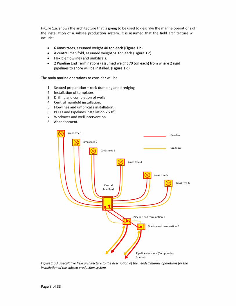
Figure 1.a. shows the architecture that is going to be used to describe the marine operations of the installation of a subsea production system. It is assumed that the field architecture will include:
• 6 Xmas trees, assumed weight 40 ton each (Figure 1.b) • A central manifold, assumed weight 50 ton each (Figure 1.c) • Flexible flowlines and umbilicals. • 2 Pipeline End Terminations (assumed weight 70 ton each) from where 2 rigid
pipelines to shore will be installed. (Figure 1.d) The main marine operations to consider will be:
1. Seabed preparation – rock‐dumping and dredging 2. Installation of templates 3. Drilling and completion of wells 4. Central manifold installation. 5. Flowlines and umbilical’s installation. 6. PLETs and Pipelines installation 2 x 8”. 7. Workover and well intervention 8. Abandonment
Figure 1.a A speculative field architecture to the description of the needed marine operations for the installation of the subsea production system.
Xmas tree 1
Xmas tree 3
Xmas tree 2
Xmas tree 4
Xmas tree 5
Xmas tree 6
Flowline
Umbilical
Central Manifold
Pipeline end termination 1
Pipeline end termination 2
Pipelines to shore (Compression Station)

Page 4 of 33
D.I.1 Sea bed preparation – rockdumping, dredging, pretrenching These operations are commonly related to the installation of pipelines; however these operations can also be required for all the subsea installations. The purpose of this operations are ensure on bottom stability, create safe foundations for the pipeline and the subsea equipment and protect against the external interference of the eventual loads.
The irregularities of the subsea bed sometimes made necessary the rock dumping operation that consists in deposit rocks to eliminate spans where the pipelines and subsea equipment are going to be installed.
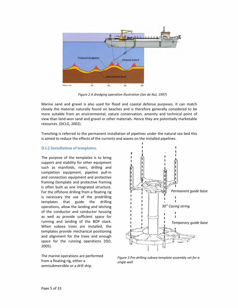
Dredging is an operation consisting on suction sand and gravel from the seabed through specialized vessels (See figure 2). The sand and gravel are present on the seabed with uneven distributions and may vary in thickness from thin layers over the bedrock or clays to many tens of meters.
Figure 1.b 15K Enhanced Horizontal Tree (EHXT)[FMC,2009]
Figure 1.c A Manifold of Norne project, Norway, [Grenland, 2009]
Figure 1.c A Pipeline end termination of the Cottonwood Field Development Project [Petrobras, 2007]
Page 5 of 33
Figure 3 Pre‐drilling subsea template assembly set for a single well
Temporary guide base
Permanent guide base
30” Casing string
Figure 2 A dredging operation illustration (Jan de Nul, 1997)
Marine sand and gravel is also used for flood and coastal defense purposes. It can match closely the material naturally found on beaches and is therefore generally considered to be more suitable from an environmental, nature conservation, amenity and technical point of view than land‐won sand and gravel or other materials. Hence they are potentially marketable resources. (DCLG, 2002). Trenching is referred to the permanent installation of pipelines under the natural sea bed this is aimed to reduce the effects of the currents and waves on the installed pipelines. D.I.2 Installation of templates. The purpose of the templates is to bring support and stability for other equipment such as manifolds, risers, drilling and completion equipment, pipeline pull‐in and connection equipment and protective framing (template and protective framing is often built as one integrated structure. For the offshore drilling from a floating rig is necessary the use of the predrilling templates that guide the drilling operations, allow the landing and latching of the conductor and conductor housing as well as provide sufficient space for running and landing of the BOP stack. When subsea trees are installed, the templates provide mechanical positioning and alignment for the trees and enough space for the running operations (ISO, 2005). The marine operations are performed from a floating rig, either a semisubmersible or a drill ship.

Page 6 of 33
An example of the sequence for these installations is described with detail in the Unit 6 Subsea completions of the Petroleum Open Learning Series of Oilwell Production Technologies (POL, 2, 2002) below is shown a summary of that example, see figure 3: 1. Lower a temporary guide base (TGB) to the sea bed. 2. Release running tool from TGB and retrieve. 3. Lower 36” drilling assembly into TGB using guide frame and guide lines. 4. Retrieve guide frame. 5. Drill 36” hole. 6. Lower 30” casing through the permanent guide base (PGB). 7. Attach 30” housing to top joint of 30” casing. 8. Connect PGB to 30” housing. 9. Lower 30” casing into hole and land PGB on to TGB. 10. Cement 30” casing. Besides a single well template, it is also common to have a multiwell template that accommodate several places for drilling wells and also another that can bring support for other kind of equipment, such as a manifold or a subsea processing system. As an example of an integrate template structure we can take a look at the Kristin Project in Norway. The Kristin Project is a gas‐condensate field considered high temperature (176°C) ‐ high pressure (911 bar), at a water depth of 360‐380 meters produces from 3 different reservoirs and is located around 190 km offshore Norway. The concept used in this development is a set of four similar templates (See figure 4.a and 4.b) that have the following characteristics. •4 slot drilling template & manifold system •Suction anchor foundation •Overtrawlable structures •Dual manifold headers with internal pig loop •Piping flexibility between X‐mas tree and manifold taken in the manifold branch piping •Full flow direction flexibility – remotely controlled branch valves •Scale squeeze system •HPHT –High Pressure High Temperature •HIPPS –High Integrity Pressure Protection System The estimate weight of the structure is 270 Tons what made its installation particularly challenging due the extreme weather conditions of the North Sea.
Figure 4.a A visualization of the systems integrated in the templates used at the Kristin fields. (Nergaard, 2008)

Page 7 of 33
A description of the activities of installation of templates was made in 1987 by Komaromy et al. below is excerpted the table of the activities and options of operations to be performed (table 2). An illustration of the installation of a subsea template from by a crane vessel is shown in figures 5.a to 5.d.
Options available for template installation
Activity Options
Loadout Lift, roll or skid Transportation Barge, crane vessel, drilIship or semisubmersible
Lift and lower Conventional four‐point lift, spreader beam or frame, auto or manual release of rigging Hard or soft slings, buoyancy assistance
Positioning Tugs, tuggers with sea‐bed anchors, tuggers from installation vessel, thrusters
Level measurement Acoustics, splint level, bulls eye
Level adjustment Jacking from mudmats or piles
Support‐pile installation Driven or drilled Preinstallation of plies in template or lowered with hammer Pile followers or underwater hammer Pile cutting
Support‐pile attachment Swaged, grouted or mechanical
Docking‐pile installation Hammer requirement and mode piles may be lowered alone, with hammer or in template
Removal of docking‐pile guide Diver or ROV Quick release or cut connection
Table 2 Activities of installation of templates (Komaromy et. al, 1987).
The planning and calculations of the activities of installation have to consider carefully three different phases of the installation.
1. Lifting in the air of the dry weight of the template from the transport barge. 2. Lowering the template into the water through the splash zone. 3. Lowering the template into the water to the sea bed.
Figure 4.4.b. Subsea template at Kristin Field. (Nergaard, 2008)

Page 8 of 33
D.I.3. Drilling and completion of wells. Before to deal on drilling and completion is going to be mentioned some details on the equipment used to perform this activities. These operations in the case of the subsea systems are performed from mobile offshore drilling units. In the case of shallow waters these operations can be performed by jack up drilling rigs (see figure 4.6.a) and in deep water is necessary the use of semisubmersibles rigs (See figure 4.6.b) or drilling ships (4.6.c).
Figure 5. Installation of a subsea template from by a crane vessel [Homer, 1993]
Petromena ASA a drilling rig constructor issued a memorandum (Petromena, 2007) about the acquisition of one of their Semi submersibles from where it is excerpted the following information in the consideration of being a good descriptive summary of the main characteristics of each unit.
Jack‐up rigs Jack‐up rigs are mobile bottom‐supported self‐elevating drilling platforms that stand on three legs on the seabed. When the rig is to move from one location to another, it will jack itself down on the water until it floats, and will be towed by a supply vessel or similar, or carried by a heavy lift and transportation vessel, to its next location. A modern jack‐up will normally have the ability to move its drill floor aft of its own hull (cantilever), so that multiple wells can be drilled at open water locations or over wellhead platforms without re‐positioning the rig. Ultra premium jack‐up rigs have enhanced operational capabilities and can work in water depths >300ft.
Figure 5.a Mobilization of manifold and crane vessel & lift manifold
Figure 5.b Lower manifold
Figure 5.c Add Rigging extensions Figure 5.d Set manifold on piles
Upper spreader bar Rigging
Crane vessel Workboat
Subsea well
Page 9 of 33
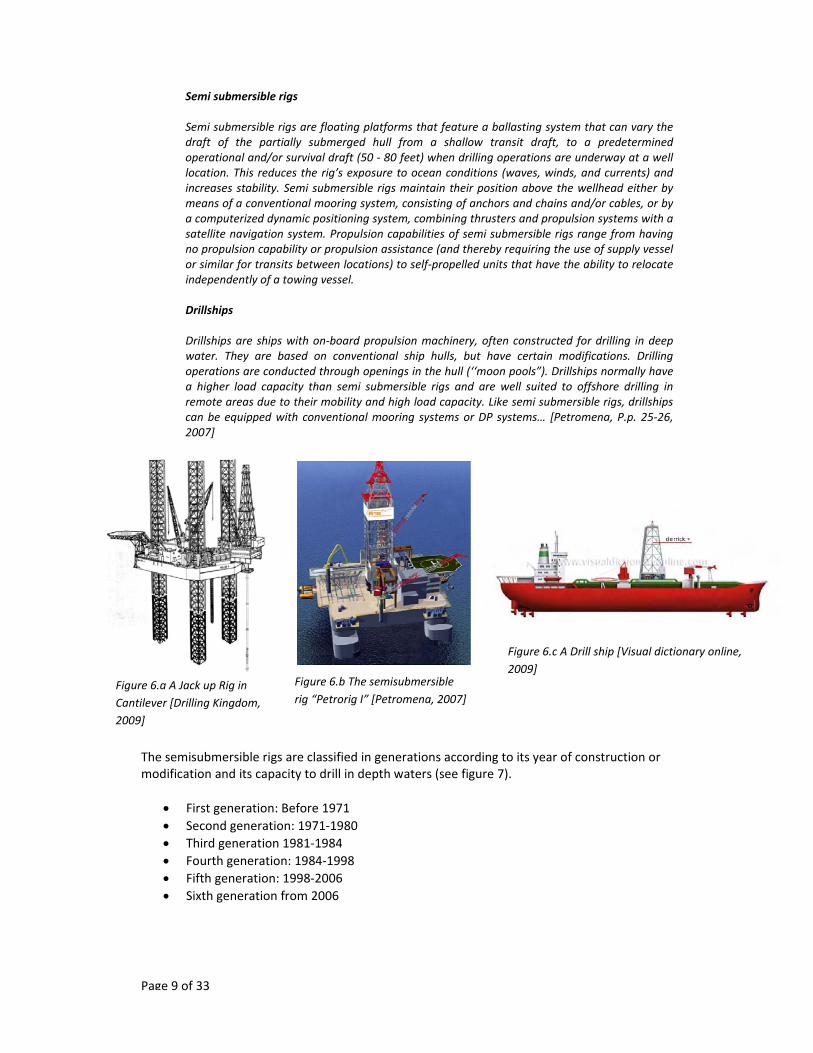
Semi submersible rigs Semi submersible rigs are floating platforms that feature a ballasting system that can vary the draft of the partially submerged hull from a shallow transit draft, to a predetermined operational and/or survival draft (50 ‐ 80 feet) when drilling operations are underway at a well location. This reduces the rig’s exposure to ocean conditions (waves, winds, and currents) and increases stability. Semi submersible rigs maintain their position above the wellhead either by means of a conventional mooring system, consisting of anchors and chains and/or cables, or by a computerized dynamic positioning system, combining thrusters and propulsion systems with a satellite navigation system. Propulsion capabilities of semi submersible rigs range from having no propulsion capability or propulsion assistance (and thereby requiring the use of supply vessel or similar for transits between locations) to self‐propelled units that have the ability to relocate independently of a towing vessel. Drillships Drillships are ships with on‐board propulsion machinery, often constructed for drilling in deep water. They are based on conventional ship hulls, but have certain modifications. Drilling operations are conducted through openings in the hull (‘‘moon pools”). Drillships normally have a higher load capacity than semi submersible rigs and are well suited to offshore drilling in remote areas due to their mobility and high load capacity. Like semi submersible rigs, drillships can be equipped with conventional mooring systems or DP systems… [Petromena, P.p. 25‐26, 2007]
The semisubmersible rigs are classified in generations according to its year of construction or modification and its capacity to drill in depth waters (see figure 7).
• First generation: Before 1971 • Second generation: 1971‐1980 • Third generation 1981‐1984 • Fourth generation: 1984‐1998 • Fifth generation: 1998‐2006 • Sixth generation from 2006
Figure 6.a A Jack up Rig in Cantilever [Drilling Kingdom, 2009]
Figure 6.c A Drill ship [Visual dictionary online, 2009]
Figure 6.b The semisubmersible rig “Petrorig I” [Petromena, 2007]

Page 10 of 33
The marine operations related to drilling start with the positioning of the rigs, both semisubmersible and drilling ships use dynamic positioning as well as mooring systems. The Wikipedia describe in a good sense the main characteristics of the Dynamic positioning (DP), (Wikipedia, 2009), figures 8 and 9 illustrate the concepts.
Dynamic positioning (DP) is a computer controlled system to automatically maintain a vessel's position and heading by using her own propellers and thrusters. Position reference sensors, combined with wind sensors, motion sensors and gyro compasses, provide information to the computer pertaining to the vessel's position and the magnitude and direction of environmental forces affecting its position.
The computer program contains a mathematical model of the vessel that includes information pertaining to the wind and current drag of the vessel and the location of the thrusters. This knowledge, combined with the sensor information, allows the computer to calculate the required steering angle and thruster output for each thruster. This allows operations at sea where mooring or anchoring is not feasible due to deep water, congestion on the sea bottom (pipelines, templates) or other problems…
Control systems
In the beginning proportional–integral–derivative controllers were used and today are still used in the simpler DP systems. But modern controllers use a mathematical
Figure 7: Main offshore rig categories by drilling depth (Petromena, 2007)
Figure 8: Simplified diagram flow of the control system for Dynamic positioning (Wikipedia, 2009)

Page 11 of 33
model of the ship that is based on a hydrodynamic and aerodynamic description concerning some of the ship's characteristics such as mass and drag. Of course, this model is not entirely correct. The ship's position and heading are fed into the system and compared with the prediction made by the model. This difference is used to update the model by using Kalman filtering technique. For this reason, the model also has input from the wind sensors and feedback from the thrusters. This method even allows not having input from any position relative system (PRS) for some time, depending on the quality of the model and the weather.
The accuracy and precision of the different PRS’s is not the same. While a Differential Global Positioning System has a high accuracy and precision, a Ultra‐ or Super‐ Short Base Line can have a much lower precision. For this reason, the PRS’s are weighed. Based on variance a PRS receives a weight between 0 and 1.
Power and propulsion systems
To maintain position azimuth thrusters (L‐drive or Z‐drive), azipods, bow thrusters, stern thrusters, water jets, rudders and propellors are used. DP ships are usually at least partially diesel‐electric, as this allows a more flexible set‐up and is better able to handle the large changes in power demand, typical for DP operations.
The set‐up depends on the DP class of the ship. A Class 1 can be relatively simple, whereas the system of a Class 3 ship is quite complex.
On Class 2 and 3 ships, all computers and reference systems should be powered through a UPS.
Class Requirements
Based on IMO (International Maritime Organization) publication 645[6] the Classification Societies have issued rules for Dynamic Positioned Ships described as Class 1, Class 2 and Class 3.
Equipment Class 1 has no redundancy: Loss of position may occur in the event of a single fault.
Equipment Class 2 has redundancy so that no single fault in an active system will cause the system to fail: Loss of position should not occur from a single fault of an active component or system such as generators, thruster, switchboards, remote controlled valves etc. But may occur after failure of a static component such as cables, pipes, manual valves etc.
Equipment Class 3 which also has to withstand fire or flood in any one compartment without the system failing: Loss of position should not occur from any single failure including a completely burnt fire sub division or flooded watertight compartment.
Mooring systems are used extensively not only in drilling but also in production, installation and service vessels. A number of anchors are fixed in the sea bed, those anchors are attached to mooring lines either of steel chain, wire or rope or a combination of them that are connected to mooring winched in the offshore unit. There are different standards related to this aspect of the marine operations below it is a list of the offered by DNV.

Page 12 of 33
o DNV‐OS‐E301 Position Mooring (issued October 2008), update of previous revision o DNV‐OS‐E302 Offshore Mooring Chain (issued October 2008), new standard o DNV‐OS‐E303 Offshore Mooring Fibre Ropes (issued April 2008), new standard o DNV‐OS‐E304 Offshore Mooring Steel Wire Rope (to be issued April 2009), new standard Figure 9: Dynamic positioning principles based on the illustration of Drilling Kingdom, 2009. The principle of installation of these anchors is more or less the same for bigger offshore units. Petroleum Open Learning Series of Oilwell Drilling Technologies describes in its unit 6 Floating Drilling Installations [POL, 1, P.p. 6.5.‐6.7, 2002]
Anchor handling work boats use a roller at their stern and two winches capable of holding the required length of pendant line. 1. The rig crane passes the anchor to the work boat, there is attached a pendant line, see figure 10 a. 2. With the anchor suspended over the stern roller, the work boat moves out to the drop point. During this time, the mooring line which is attached to the anchor is payed out from the mooring winches on the drilling rig, as shown in figure 10 b. 3. At the required distance from the rig, the anchor is lowered to the sea bed on the pendant line. Figure 10 c. 4. With the rig holding in tension on the mooring line the anchor digs in to the sea bed. The work boat then attached a marker buoy to the pendant line and leaves it floating on the sea surface. Figure 10 d
DGPS
INMARSAT GPS
AZIMUTHAL THRUSTER
AZIMUTHAL THRUSTER

Page 13 of 33
Figure 10 a. Figure 10 b.
Figure 10 c. Figure 10 d. The configurations of patters can be classified in different types according to its shape. In deep water up to up to 1000 m the catenary mooring system is made of lines of chain and/or wire rope (Figure 11.a). For exploration and production beyond 1000 m, the weight of the mooring line is a limiting factor in the design of the floater. To overcome this problem new solutions have been devised consisting of synthetic ropes in the mooring line (less weight) and/or a taut leg mooring system (Figure 11.b) (Ruinen, 2003). Figure 11.a Catenary mooring system Figure 11.b. Taut leg mooring system. Once the drilling rig is properly positioned and fixed over the well location a series of drilling operations are performed, below is a list of an example for a deep water field with a multiwell template by Nergaard in the class subsea production system (Nergaard, 2009). These operations require the Running and set of BOP and Xmas trees over the template; due the weight in skid of these components (approximately 250 ton and 40 ton) these positioning and setting are considered to be important marine operations.
1. Drill 30 ‐ 36” pilot hole to approx. 120 m below seabed, figure 12.a. 2. Run land and cement conductor casing (30”), figure 12.b. 3. Drill 24” surface hole to approx. 500 m and run 20” surface casing, figure 12.c. 4. Run land and cement 20” casing, figure 12.d.

Page 14 of 33
5. Run BOP, figure 12.e. 6. Land BOP, drill and complete well no. 1 and spud well no.2, figure 12.f. 7. Move BOP to well no 2 and run Xmas tree to well no 1. Figure 12.g.
Figure 12.a Figure 12.b Figure 12.c
Figure 12.d Figure 12.e Figure 12.f

Page 15 of 33
Figure 12.f
D.I.4 Central manifold installation. Similar marine operations to install templates.
D.I.5 Flowlines and umbilical’s installation. A good summary on how to install and connect flowlines and umbilicals is available in the appendix A, Sections A.9.2 and A.9.3 of the International Standard ISO 13628‐1 Design and operation of subsea production systems.
A.9.2 Flowline and umbilical configurations and installation techniques A.9.2.1 General Many factors need to be taken into account in the design of the flowlines and umbilicals for a subsea production system. The combination of through‐life design requirements, installation options and life‐cyclecosts will result in the selection of a preferred configuration and installation technique, the basic ones of which are outlined below. A.9.2.2 Individual flowlines Individual flowlines can be installed using S‐lay, J‐lay, reel (including pipe‐in‐pipe) and/or tow techniques as follows: ‐ S‐lay; The flowline is made up in a horizontal or near horizontal position on the lay vessel and lowered to the seafloor in an elongated “S” shape as the vessel moves forward.

Page 16 of 33
‐ J‐lay; The flowline is made up in a vertical or near‐vertical position on the lay vessel and lowered to the seafloor in a near‐vertical orientation. This approach eliminates the overbend region of the S‐lay pipe catenary. ‐ Reel; The flowline is made up onshore and spooled onto a reel. The line is then transported to the desired location and unreeled onto the seafloor. The axis of the reel may be vertical or horizontal. ‐ tow. The flowline is made up onshore or in a mild offshore environment and then towed to its final location, where the buoyancy is adjusted to lower the line to the seafloor and provide adequate on‐bottom stability. There are several versions of the tow method, including the near‐surface tow, controlled‐depth tow, nearbottom tow and bottom tow. The tow methods differ primarily in the requirements for buoyancy control and in their sensitivity to environmental loadings during the towout. All of these techniques have limits with respect to the largest diameter lines that can be fabricated and installed. Reeling and towing also have some restrictions with respect to the length of line that can be fabricated and installed in a single run/unit. Whereas the host end of a reeled flowline can be pulled up a J‐or I‐tube, most of the other techniques rely on the use of spools/jumpers at the host end. In the case of a tieback to an FPS, the tail end of an individual rigid pipe or flexible pipe may be suspended from the FPS to form a riser, as described in A.10.3. The various connection options for the ends of individually installed flowlines are described in detail in A.9.9. A.9.2.3 Bundles Small numbers of flowlines and/or umbilicals can be strapped together during reeling operations to form a strapped bundle on the seabed. While this configuration can have some advantages in terms of on‐bottom stability of the lines, etc., the benefits are somewhat limited as each line shall be at least partially designed on a stand‐alone basis...[ISO‐13628‐1, P.p. 131‐132, 2005]. A.9.3 Flowline and umbilical end connections A.9.3.1 General In order for a flowline or umbilical to fulfil its intended function, it is necessary to connect it to the associated subsea/surface facility equipment. A wide variety of techniques are available to complete this task, ranging from installation of flexible jumpers by divers at the subsea end of a flowline, through to pulling a multicore umbilical up through a J‐tube preinstalled on a production platform. For connection of flowlines and umbilicals to subsea/surface equipment, the basic steps involved in the process are the following: ‐ pull‐in of the two halves of the connector so that the faces are aligned and in close proximity (alternatively, the gap between the two halves of the connection may be spanned by an additional short length of sealine known as a jumper or spool); ‐ connection of the two halves of the connector; ‐ testing of the completed connection, to confirm that it has been successfully made up. ...[ISO‐13628‐1, P.p. 133‐134, 2005].