Embed Size (px)
Citation preview
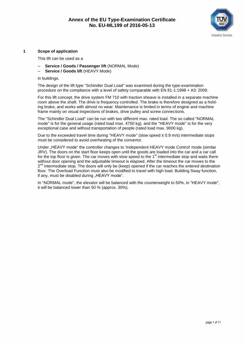
Annex of the EU Type-Examination Certificate No. EU-ML199 of 2016-05-13
page 1 of 11
1 Scope of application
This lift can be used as a
– Service / Goods / Passenger lift (NORMAL Mode)
– Service / Goods lift (HEAVY Mode)
in buildings.
The design of the lift type "Schindler Dual Load" was examined during the type-examination procedure on the compliance with a level of safety comparable with EN 81-1:1998 + A3: 2009.
For this lift concept, the drive system FM 710 with traction sheave is installed in a separate machine room above the shaft. The drive is frequency controlled. The brake is therefore designed as a hold-ing brake, and works with almost no wear. Maintenance is limited in terms of engine and machine frame mainly on visual inspections of brakes, drive pulley and screw connections.
The "Schindler Dual Load" can be run with two different max. rated load. The so called "NORMAL mode" is for the general usage (rated load max. 4750 kg), and the "HEAVY mode" is for the very exceptional case and without transportation of people (rated load max. 9000 kg).
Due to the exceeded travel time during "HEAVY mode" (slow speed ≤ 0.9 m/s) intermediate stops must be considered to avoid overheating of the convertor.
Under „HEAVY mode“ the controller changes to 'Independent HEAVY mode Control' mode (similar JRV). The doors on the start floor keeps open until the goods are loaded into the car and a car call for the top floor is given. The car moves with slow speed to the 1
st intermediate stop and waits there
without door opening and the adjustable timeout is elapsed. After the timeout the car moves to the 2
nd intermediate stop. The doors will only be (keep) opened if the car reaches the entered destination
floor. The Overload Function must also be modified to travel with high load. Building Sway function, if any, must be disabled during „HEAVY mode“.
In "NORMAL mode", the elevator will be balanced with the counterweight to 50%, in "HEAVY mode", it will be balanced lower than 50 % (approx. 30%).
Annex of the EU Type-Examination Certificate No. EU-ML199 of 2016-05-13
page 2 of 11
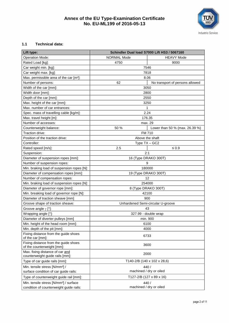
1.1 Technical data:
Lift type: Schindler Dual load S7000 Lift HS3 / 5067160
Operation Mode: NORMAL Mode HEAVY Mode
Rated Load [kg]: 4750 9000
Car weight min. [kg]: 7546
Car weight max. [kg]: 7818
Max. permissible area of the car [m²]: 8.06
Number of persons: 62 No transport of persons allowed
Width of the car [mm]: 3050
Width door [mm]: 2800
Depth of the car [mm]: 2550
Max. height of the car [mm]: 3250
Max. number of car entrances: 1
Spec. mass of travelling cable [kg/m]: 2.24
Max. travel height [m]: 176.35
Number of accesses: max. 29
Counterweight balance: 50 % Lower than 50 % (max. 26.39 %)
Traction drive: FM 710
Position of the traction drive: Above the shaft
Controller: Type TX – GC2
Rated speed [m/s]: 2.5 ≤ 0.9
Suspension: 2:1
Diameter of suspension ropes [mm]: 16 (Type DRAKO 300T)
Number of suspension ropes: 9
Min. braking load of suspension ropes [N]: 180000
Diameter of compensation ropes [mm]: 19 (Type DRAKO 300T)
Number of compensation ropes: 12
Min. braking load of suspension ropes [N]: 254000
Diameter of governor rope [mm]: 8 (Type DRAKO 300T)
Min. breaking load of governor rope [N]: 42100
Diameter of traction sheave [mm] 900
Groove shape of traction sheave: Unhardened Semi-circular U-groove
Groove angle [°]: 43
Wrapping angle [°]: 327.99 - double wrap
Diameter of diverter pulleys [mm] min. 900
Min. height of the head room [mm]: 6100
Min. depth of the pit [mm]: 4000
Fixing distance from the guide shoes of the car [mm]:
6733
Fixing distance from the guide shoes of the counterweight [mm]:
3600
Max. fixing distance of car and counterweight guide rails [mm]:
2000
Type of car guide rails [mm]: T140-2/B (140 x 102 x 28,6)
Min. tensile stress [N/mm²] /
surface condition of car guide rails:
440 / machined / dry or oiled
Type of counterweight guide rail [mm]: T127-2/B (127 x 89 x 16)
Min. tensile stress [N/mm²] / surface
condition of counterweight guide rails:
440 / machined / dry or oiled
Annex of the EU Type-Examination Certificate No. EU-ML199 of 2016-05-13
page 3 of 11
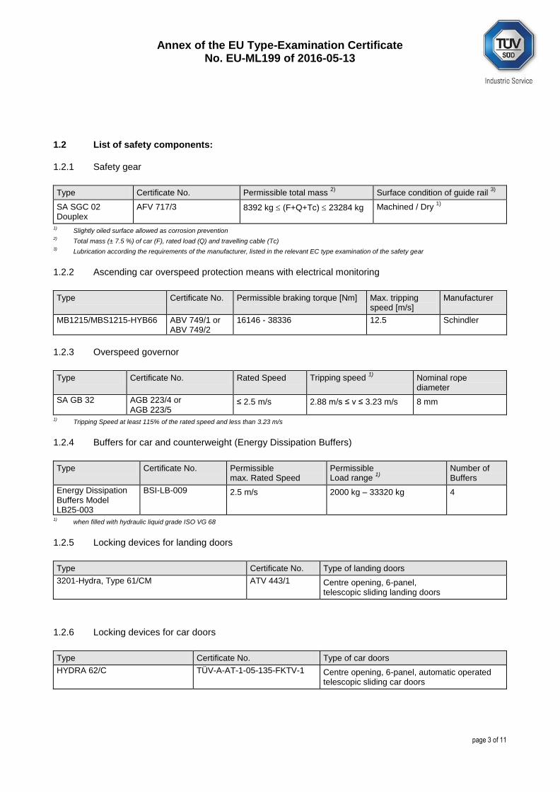
1.2 List of safety components:
1.2.1 Safety gear
Type Certificate No. Permissible total mass 2)
Surface condition of guide rail 3)
SA SGC 02 Douplex
AFV 717/3 8392 kg (F+Q+Tc) 23284 kg Machined / Dry 1)
1) Slightly oiled surface allowed as corrosion prevention
2) Total mass (± 7.5 %) of car (F), rated load (Q) and travelling cable (Tc)
3) Lubrication according the requirements of the manufacturer, listed in the relevant EC type examination of the safety gear
1.2.2 Ascending car overspeed protection means with electrical monitoring
Type Certificate No. Permissible braking torque [Nm] Max. tripping speed [m/s]
Manufacturer
MB1215/MBS1215-HYB66 ABV 749/1 or ABV 749/2
16146 - 38336 12.5 Schindler
1.2.3 Overspeed governor
Type Certificate No. Rated Speed Tripping speed 1)
Nominal rope diameter
SA GB 32 AGB 223/4 or AGB 223/5
≤ 2.5 m/s 2.88 m/s ≤ v ≤ 3.23 m/s 8 mm
1) Tripping Speed at least 115% of the rated speed and less than 3.23 m/s
1.2.4 Buffers for car and counterweight (Energy Dissipation Buffers)
Type Certificate No. Permissible max. Rated Speed
Permissible Load range
1)
Number of Buffers
Energy Dissipation Buffers Model LB25-003
BSI-LB-009 2.5 m/s 2000 kg – 33320 kg 4
1) when filled with hydraulic liquid grade ISO VG 68
1.2.5 Locking devices for landing doors
Type Certificate No. Type of landing doors
3201-Hydra, Type 61/CM ATV 443/1 Centre opening, 6-panel, telescopic sliding landing doors
1.2.6 Locking devices for car doors
Type Certificate No. Type of car doors
HYDRA 62/C TÜV-A-AT-1-05-135-FKTV-1 Centre opening, 6-panel, automatic operated telescopic sliding car doors
Annex of the EU Type-Examination Certificate No. EU-ML199 of 2016-05-13
page 4 of 11
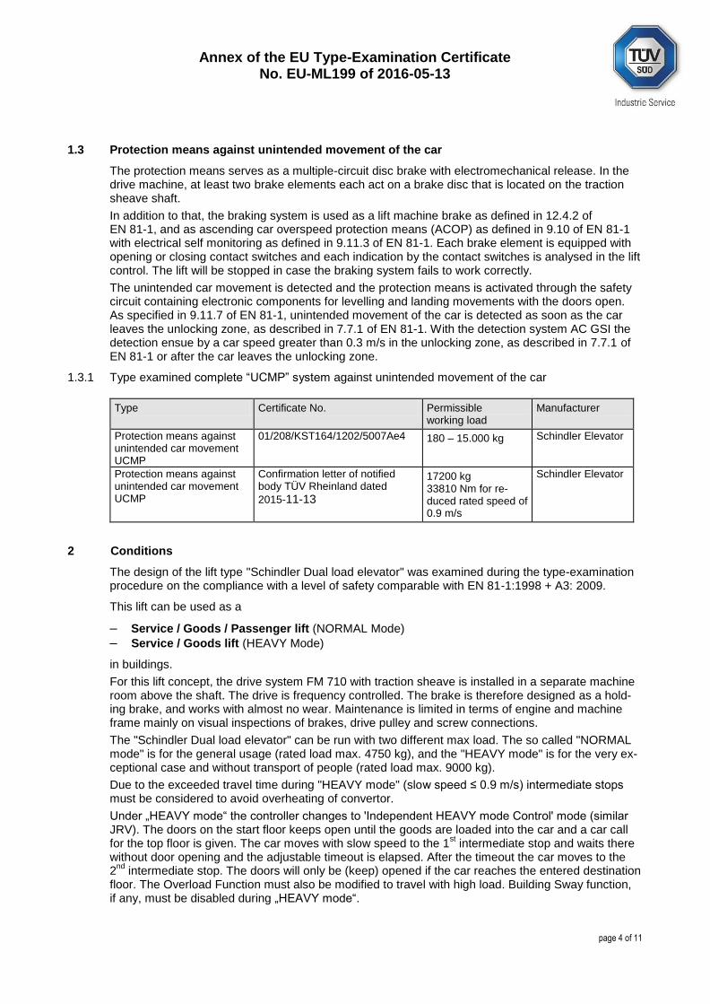
1.3 Protection means against unintended movement of the car
The protection means serves as a multiple-circuit disc brake with electromechanical release. In the drive machine, at least two brake elements each act on a brake disc that is located on the traction sheave shaft.
In addition to that, the braking system is used as a lift machine brake as defined in 12.4.2 of EN 81-1, and as ascending car overspeed protection means (ACOP) as defined in 9.10 of EN 81-1 with electrical self monitoring as defined in 9.11.3 of EN 81-1. Each brake element is equipped with opening or closing contact switches and each indication by the contact switches is analysed in the lift control. The lift will be stopped in case the braking system fails to work correctly.
The unintended car movement is detected and the protection means is activated through the safety circuit containing electronic components for levelling and landing movements with the doors open. As specified in 9.11.7 of EN 81-1, unintended movement of the car is detected as soon as the car leaves the unlocking zone, as described in 7.7.1 of EN 81-1. With the detection system AC GSI the detection ensue by a car speed greater than 0.3 m/s in the unlocking zone, as described in 7.7.1 of EN 81-1 or after the car leaves the unlocking zone.
1.3.1 Type examined complete “UCMP” system against unintended movement of the car
Type Certificate No. Permissible working load
Manufacturer
Protection means against unintended car movement UCMP
01/208/KST164/1202/5007Ae4 180 – 15.000 kg Schindler Elevator
Protection means against unintended car movement UCMP
Confirmation letter of notified body TÜV Rheinland dated
2015-11-13
17200 kg 33810 Nm for re-duced rated speed of 0.9 m/s
Schindler Elevator
2 Conditions
The design of the lift type "Schindler Dual load elevator" was examined during the type-examination procedure on the compliance with a level of safety comparable with EN 81-1:1998 + A3: 2009.
This lift can be used as a
– Service / Goods / Passenger lift (NORMAL Mode)
– Service / Goods lift (HEAVY Mode)
in buildings.
For this lift concept, the drive system FM 710 with traction sheave is installed in a separate machine room above the shaft. The drive is frequency controlled. The brake is therefore designed as a hold-ing brake, and works with almost no wear. Maintenance is limited in terms of engine and machine frame mainly on visual inspections of brakes, drive pulley and screw connections.
The "Schindler Dual load elevator" can be run with two different max load. The so called "NORMAL mode" is for the general usage (rated load max. 4750 kg), and the "HEAVY mode" is for the very ex-ceptional case and without transport of people (rated load max. 9000 kg).
Due to the exceeded travel time during "HEAVY mode" (slow speed ≤ 0.9 m/s) intermediate stops must be considered to avoid overheating of convertor.
Under „HEAVY mode“ the controller changes to 'Independent HEAVY mode Control' mode (similar JRV). The doors on the start floor keeps open until the goods are loaded into the car and a car call for the top floor is given. The car moves with slow speed to the 1
st intermediate stop and waits there
without door opening and the adjustable timeout is elapsed. After the timeout the car moves to the 2
nd intermediate stop. The doors will only be (keep) opened if the car reaches the entered destination
floor. The Overload Function must also be modified to travel with high load. Building Sway function, if any, must be disabled during „HEAVY mode“.
Annex of the EU Type-Examination Certificate No. EU-ML199 of 2016-05-13
page 5 of 11
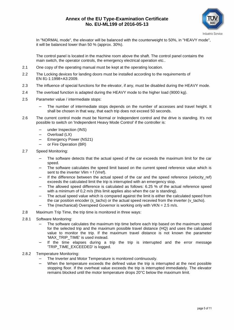
In "NORMAL mode", the elevator will be balanced with the counterweight to 50%, in "HEAVY mode", it will be balanced lower than 50 % (approx. 30%).
The control panel is located in the machine room above the shaft. The control panel contains the main switch, the operator controls, the emergency electrical operation etc..
2.1 One copy of the operating manual must be kept at the operating location.
2.2 The Locking devices for landing doors must be installed according to the requirements of EN 81-1:1998+A3:2009.
2.3 The influence of special functions for the elevator, if any, must be disabled during the HEAVY mode.
2.4 The overload function is adapted during the HEAVY mode to the higher load (9000 kg).
2.5 Parameter value / intermediate stops:
– The number of intermediate stops depends on the number of accesses and travel height. It shall be chosen in that way, that each trip does not exceed 50 seconds.
2.6 The current control mode must be Normal or Independent control and the drive is standing. It's not possible to switch on 'Independent Heavy Mode Control' if the controller is:
– under Inspection (INS)
– Overload (LX)
– Emergency Power (NS21)
– or Fire Operation (BR)
2.7 Speed Monitoring:
– The software detects that the actual speed of the car exceeds the maximum limit for the car speed.
– The software calculates the speed limit based on the current speed reference value which is sent to the inverter Vlim = f (Vref).
– If the difference between the actual speed of the car and the speed reference (velocity_ref) exceeds the calculated limit the trip is interrupted with an emergency stop.
– The allowed speed difference is calculated as follows: 6.25 % of the actual reference speed with a minimum of 0,2 m/s (this limit applies also when the car is standing).
– The actual speed value which is compared against the limit is either the calculated speed from the car position encoder (s_tacho) or the actual speed recevied from the inverter (v_tacho).
– The (mechanical) Overspeed Governor is working only with VKN = 2.5 m/s.
2.8 Maximum Trip Time, the trip time is monitored in three ways:
2.8.1 Software Monitoring:
– The software calculates the maximum trip time before each trip based on the maximum speed for the selected trip and the maximum possible travel distance (HQ) and uses the calculated value to monitor the trip. If the maximum travel distance is not known the parameter 'MAX_TRIP_TIME' is used instead.
– If the time elapses during a trip the trip is interrupted and the error message 'TRIP_TIME_EXCEEDED' is logged.
2.8.2 Temperature Monitoring:
– The Inverter and Motor Temperature is monitored continuously.
– When the temperature exceeds the defined value the trip is interrupted at the next possible stopping floor. If the overheat value exceeds the trip is interrupted immediately. The elevator remains blocked until the motor temperature drops 20°C below the maximum limit.
Annex of the EU Type-Examination Certificate No. EU-ML199 of 2016-05-13
page 6 of 11
2.9 The process steps for the changeover are defined as follows:
2.9.1 Switching from NORMAL MODE to the HEAVY MODE must be performed only by specially trained professionals of Schindler Company.
2.9.2 Make sure no person accesses the car until the lift is set back to NORMAL mode.
2.9.3 Switch the main power off and secure it against being switched on again. Change winding connec-tion at the wiring switch connection box to serial winding D378 (HEAVY mode). Connect the FM710 to the supplied terminal block.
2.9.4 Activate key switch described as “JLOAD”. This key switch is located in the controller. The controller is located in the machine room. The key switch “JLOAD” is activating the HEAVY mode and allows the Certified Service Technician from Schindler to use the lift with max. load (GQ) and max. speed (VKN) of the HEAVY mode.
2.9.5 Switch power on.
2.9.6 Make sure that with activating the key switch described as “JLOAD” the following software parameter are changed to HEAVY mode according to Schindler Method Statement no. CJ_36304500 dated 2016-05-04 (10 pages)
2.9.7 Move the car to the heavy good loading level (press designation floor on SMLCD).
2.9.8 Heavy goods loading/unloading is allowed now according to Schindler Method Statement no. CJ_36304500 dated 2016-05-04 (10 pages).
2.9.9 Move the heavy goods into the car. Consider the loading/unloading restrictions according to Schindler Method Statement no. CJ_36304500 dated 2016-05-04 (10 pages). Also be aware that during loading rope elongation will cause the elevator car to move down of floor level. At this moment the car will re-level to its original position.
2.9.10 Fix the goods properly so that no moving is possible.
2.9.11 Double-check that no passenger stays in the car.
2.9.12 Move the car with the goods to the unloading level (press designation floor on SMLCD).
2.9.13 Move the heavy goods out of the car. Unload according to loading restrictions described in Schindler Method Statement no. CJ_36304500 dated 2016-05-04 (10 pages). Be aware that during unloading rope contraction will cause the elevator car to move up from floor level. At this moment the car will re-level to its original position.
2.9.14 Switch the main power off and secure it against being switched on again.
2.9.15 Change winding connection at the wiring switch connection box to serial winding D126 (NORMAL mode) according to the locally provided schematic and according to Schindler Method Statement no. CJ_36304500 dated 2016-05-04 (10 pages).
2.9.16 Deactivate key switch described as “JLOAD”. This key switch is located in the controller. The control-ler is located in the machine room. The key switch “JLOAD” is deactivating the HEAVY mode and gives the lift free to the general operation in NORMAL mode with max. load (GQ) and max. speed (VKN) of the NORMAL mode.
2.9.17 Switch power on.
2.9.18 Make sure that the key switch described as “JLOAD” is deactivated and the following software pa-rameter are changed to NORMAL mode according to Schindler Method Statement no. CJ_36304500 dated 2016-05-04 (10 pages).
Annex of the EU Type-Examination Certificate No. EU-ML199 of 2016-05-13
page 7 of 11
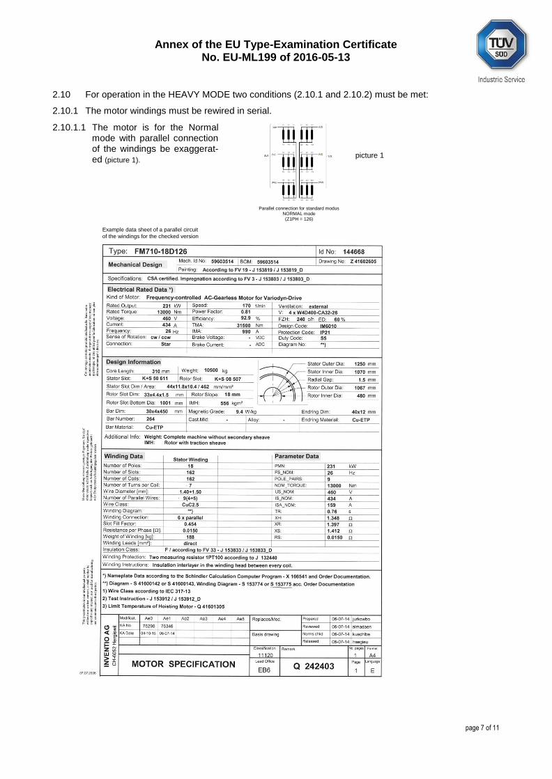
2.10 For operation in the HEAVY MODE two conditions (2.10.1 and 2.10.2) must be met:
2.10.1 The motor windings must be rewired in serial.
2.10.1.1 The motor is for the Normal mode with parallel connection of the windings be exaggerat-ed (picture 1).
Parallel connection for standard modus NORMAL mode (Z1PH = 126)
picture 1
Example data sheet of a parallel circuit
of the windings for the checked version
Annex of the EU Type-Examination Certificate No. EU-ML199 of 2016-05-13
page 8 of 11
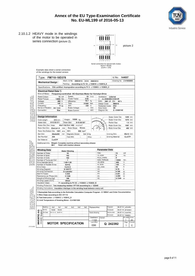
2.10.1.2 HEAVY mode in the windings of the motor to be operated in
series connection (picture 2).
Serial connection for special trafo modus HEAVY MODE (Z1PH = 378)
picture 2
Example data sheet a serial connection of the windings for the tested version
Annex of the EU Type-Examination Certificate No. EU-ML199 of 2016-05-13
page 9 of 11
2.10.2 The parameters for the HEAVY MODE must be connected using a key switch.
2.10.2.1 Motor Type: FM710-D126 (NORMAL mode, with parallel winding) or FM710-D378 (HEAVY mode, with serial
winding) VCOM telegram controller: VXT_SINGLE_PARAM with Motor Identnumber 144668 or 144657
2.10.2.2 Speed: VCOM telegram controller: VXT_CMD_LIFT – DRIVE_SPEED_MODE
2.10.2.3 Acceleration: VCOM telegram controller: VXT_CMD_LIFT – DRIVE_ACCEL_MODE
2.10.2.4 Balancing: VCOM telegram controller: VXT_SINGLE_PARAM with KG 50% or 26.39%
2.10.2.5 Load measurement: OVERLOAD_FLAG Evaluation will be made at 110% of rated load NORMAL mode or 105% of
rated load HEAVY mode.
2.11 When any initial commissioning tests for UCM, catch up, and catch traction for both load cases must be carried out. For the capture probe is understood by a respective speed of 2.5 m/s because of the speed limiter triggers for both load cases at 2.5 m/s.
2.12 For the switching only the combination of motor FM710-18D126(paralell) / 378 (serial) with the in-verter type VF288PF1 AC (2x) are allowed.
2.13 The force on the sill FS was calculated with FS = 0.6 * gn * Q. The correct loading of the heavy load and the correct placement of the heavy load must be done according to Schindler Method Statement Schindler Dual Load no. CJ_36304500 dated 2016-05-04 (10 pages).
2.14 The change from "NORMAL mode" into "HEAVY mode" and back shall only be performed by special trained personnel from Schindler Company. It is strictly forbidden to change the operating mode of the "Schindler Dual Load" without trained personnel from Schindler Company.
2.15 The controller must also contain an electrical operating device for the machine brake (which allows to test the dual circuit brake) – acting separately for the two brake shoes – including as safety device (e.g. lockable) against inadvertent release of the machine brake. The device must also work in case of power failure.
2.16 The machine room shall be provided with permanently installed electric lighting with an intensity of at least 200 lux at floor level. The supply for this lighting shall be in conformity with 13.6.1.
2.17 In front of the controller – over the full width of the control cabinet (at least 50 cm) - a horizontal clearance of at least 70 cm is required. If the space in front of the controller is accessible to the pub-lic, horizontal clearance of at least 120 cm is required. In special cases, even greater clearance may be necessary. It is essential that a free working-space depth of 70 cm is ensured under all circum-stances.
2.18 The control panel must be installed in weatherproof areas. If the controller is installed outside, the atmospheric conditions and their influences on the lift system must be examined separately.
2.19 Live parts in the control panel must be protected against direct contact.
2.20 The electrical devices in the controller must be protected according to protection class IP2X as a minimum.
2.21 The lift must be equipped with a Remote alarm system according to EN 81-28.
2.22 The shaft ventilation must be capable to dissipate the heat amount generated and must not affect negatively on the control and the drive (humidity, cold).
2.23 Through this type-examination certificate the use as firefighter lifts as well as the use in potentially explosive environment is not covered.
2.24 In the presence of one (or more) other lifts in the same shaft, the areas of the lifts in the pit has to be separated from each other, so that it is not possible to access the danger zone of a lift from the dan-ger zone of another one inside the pit.
Annex of the EU Type-Examination Certificate No. EU-ML199 of 2016-05-13
page 10 of 11
2.25 The mechanical parts of the lift must comply with the EN 1090-2.
2.26 The electrical parts of the lift must comply with the EN 60204-1.
2.27 It must be assured through technical measures that the empty car cannot be raised, when the counterweight rests on its compressed buffers.
2.28 After an unintended movement of the car according to EN 81-1, number 9.11 occurs and the protection means against according number 1.3 of this certificate is activation, it shall not be possible to activate normal operation after power switch of.
2.29 During first inspection of the lift, the following procedure must be applied:
– Trigger manually the overspeed governor triggering device in order to prevent unintended movement of the car during loading
– activate inspection control mode in order to prevent relevelling during loading.
– After loading the rated load for “HEAVY Mode”, release the brake and check if the safety gear will stop the car.
2.30 The EU type-examination certificate may only be used in connection with the pertinent annex and the enclosure (list of the authorised manufacturer of series production). This enclosure shall be updated and re-edited following information of the certificate holder.
3 Remarks
3.1 This EU type-examination was issued on basis of the following harmonised standards:
EN 81-1:1998 + A3:2009 (D)
In case of changes resp. amendments of the above-named standards resp. advancements of the state of the art, a revision of this EU type-examination certificate will be necessary.
3.2 In order to place the lift on the market, the requirements outlined in Directive 2014/33/EU Article 15 must be met (Conformity Assessment Procedure).
3.3 In cases involving changes of or deviations from the inspected model lift which are not included in section 1: „Scope of application“, the notified body must either subject the lift to individual tests as per Annex VIII or extend the scope of application.
3.4 Further requirements (e.g. constructional) of the corresponding state, where the lift is going to be installed in a building, must be observed (e. g. well ventilation, fire protection, user-panel suitable for handicapped people). This also applies when glass is used for the walls of the lift shaft.
3.5 If cars with glass walls or landing and/or car doors with door panels made of glass are used, the requirements outlined in EN 81-1:1998 + A3:2009, Annex J, Tables J1 or J2 must be observed or proof of successfully completed pendulum shock tests as per EN 81-1:1998 + A3:2009, Annex J must be enclosed with the technical documentation.
3.6 In order to avoid dragging of children hands, automatic power operated horizontally sliding doors made of dimensions greater than stated in EN 81-1:1998 + A3:2009, clause 7.6.2 shall be provided with means (e.g. according EN 81-1:1998 + A3:2009, clause 7.2.3.6) to minimize this risk.
3.7 The measures and their impact on the limitation of the closing and moving force of the horizontal sliding landing doors are not part of the EU type-examination of the locking device.
3.8 Judgement of behaviour of the landing doors in case of fire is not an integrant part of the EU type-examination Certificate of the locking device.
3.9 At the model lift, in addition to the mark of the complete locking device, there shall be a label with the information necessary for the component’s identification with the name of the manufacturer, EU type-examination sign and details of type.

Annex of the EU Type-Examination Certificate No. EU-ML199 of 2016-05-13
page 11 of 11
3.10 The following documents must be enclosed with the technical documentation of each lift as a mini-mum requirement:
– the EU type-examination certificate EU-ML199 dated 2016-05-13 with annex
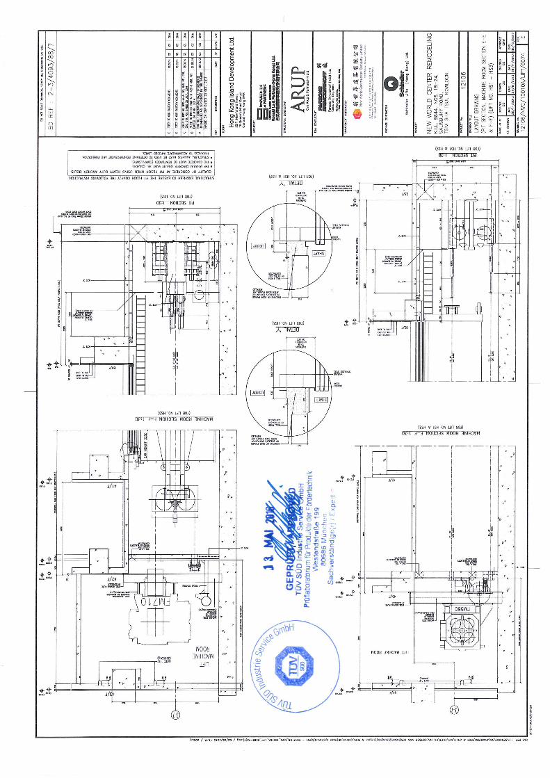
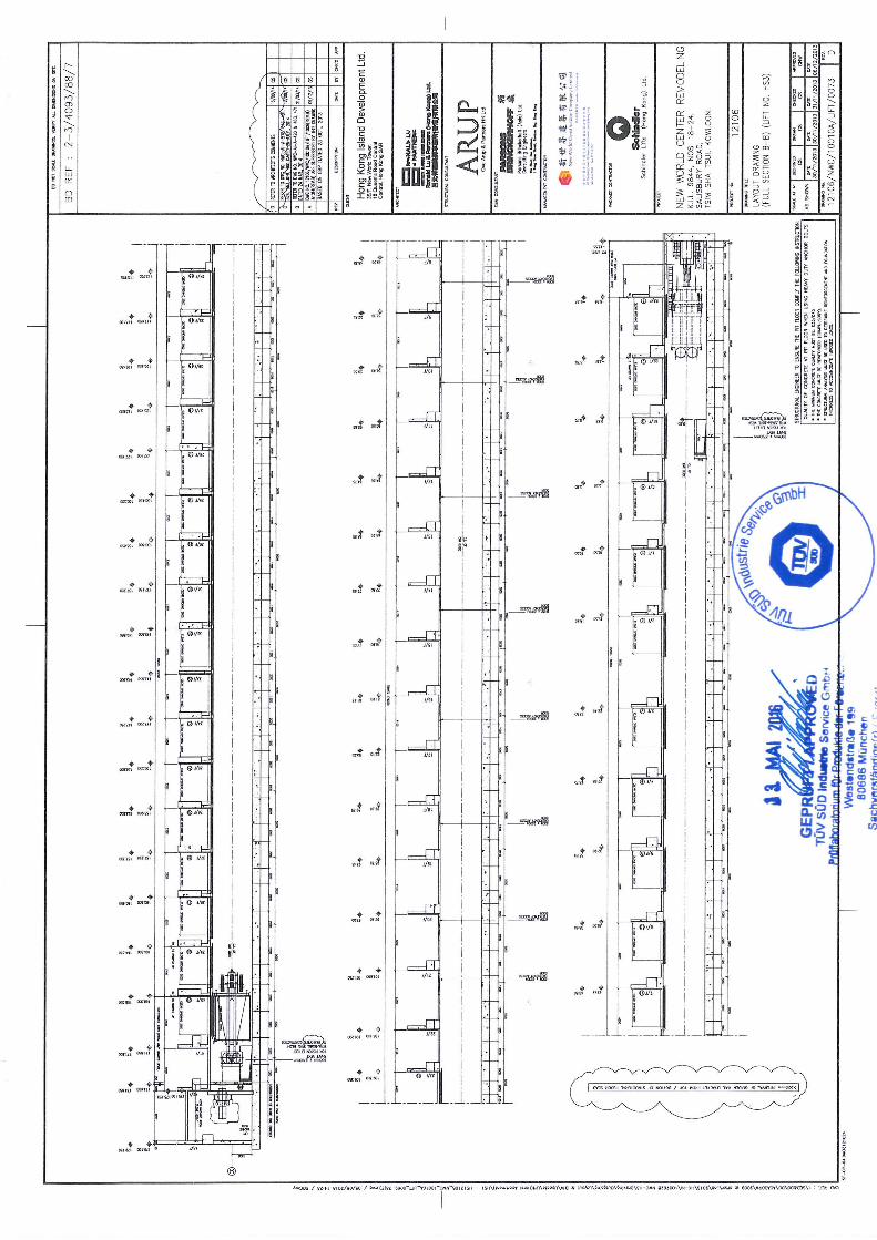
– principle drawings no. 12106/NWC/10010A/LIFT/0073 with revision index ‘D’ dated 2014-09-16 (1 sheet) and no. 12106/NWC/10010A/LIFT/0074 with revision index ‘E’ dated 2014-09-16 with test remark dated 2016-05-13
– The operating manual of the lift type "Schindler Dual Load" with operating instructions, main-tenance and service manual for maintenance personnel, information about service intervals, as well as malfunction and maintenance proof documents.
and lift specific:
– The technical dossier of the lift according to EN 81-1:1998 + A3:2009, annex C, number 2, in-cluding the list of used safety component with the corresponding type-examination certificates and annexes to the certificates, if necessary with information about specific features or devia-tions from the type-tested lift system,
– Drawings of the lift system
– Wiring diagram with references to system-specific options
The conditions of the EU type-examination certificates of the safety components used must be kept, the remarks shall be taken into account.
3.11 A Temperature in the lift shaft of +5 C to +40 C is being presupposed
3.12 An Emergency stop switch shall be located close to the drive and in the pit.
3.13 This EU type-examination certificate may be used only in connection with the pertinent Annex.
3.14 This EU type-examination certificate is based on the state of art, which is documented by currently valid harmonized standards. If any changes or additions to these standards or for development of the state of the art, a revision may be necessary.
3.15 This EU type-examination does not cover the use of the lift as a fire fighting lift (EN 81-72) as well as the use in an explosive environment.