Embed Size (px)
Citation preview
ANNEXE E
C'S'O' E-1
COURBES D'ÉMISSION ACOUSTI.QUE DES ÉOLIENNES
CONSIDÉRÉES
Projet de parc éolien � Hannut-Thisnes

.,; ENERCON Estimated Sound Power Level E-101 Page #IIItI ENERGY FOR THE WORLD 1 of 3
Imprint
Editor:
Telephone: Fax:
Estimated
Sound Power level
of the
ENERCON E-101
Operational Mode 1
(Data Sheet)
ENERCON GmbH· Dreekamp 5 • 26605 Aurich • Germany
04941-927-0 04941-927-109
Copyright: Unless otherwise specified in this document. the contents of this document are protected by copyright of ENERCON GmbH. Ali rights reserved. No use. including any copying or publishing. of this information is permitted wilhout the prior written consent of ENERCON GmbH.
Updales: ENERCON GmbH reserves the right to continuously update and modify Ihis document and the �ems described therein at any time without prior notice.
Revision
Revision:
Department:
Glossary
1.0
ENERCON GmbH / Site Assessment
WEC means an ENERCON wind energy converter.
WECs means more than one ENERCON wind energy converter.
Document information: © Copyright ENERCON GmbH. Ali rights reserved.
AuthorfRevisorf date: Schf June 2010 Documentname SIAS-04-SPL E-101 OM 1 3MW Est Rev1_0-eng-eng.doc Approved f date: JStf June 2010 Revision Idate: 1.0 Translation f date 1.0
� ENERCON Estimated Sound Power Level E-101 Page #IIIt# ENERGY FOR THE WORLD 2 of 3
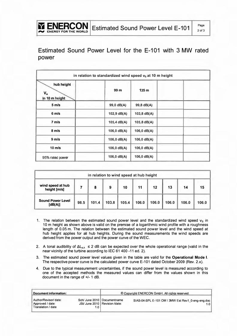
Estimated Sound Power Level for the E-101 with 3 MW rated power
in relation to standardized wind speed Vs at 10 m height
� 99m 135 m Vs
in 10 m height
5 mIs 99,0 dB(A) 99,8 dB(A)
6 mIs 102,9 dB(A) 103,8 dB(A)
7 mIs 105,4 dB(A) 105,8 dB(A)
8 mIs 106,0 dB(A) 106,0 dB(A)
9 mIs 106,0 dB(A) 106,0 dB(A)
10 mIs 106,0 dB(A) 106,0 dB(A)
95% rated power 106,0 dB(A) 106,0 dB(A)
in relation to w ind speed at hub height
wind speed at hub 7 8 9 10 11 12 13 14 15 height [mIs]
Sound Power Level 98.5 101.4 103.8 105.4 106.0 106.0 106.0 106.0 106.0 [dB(A)]
1. The relation between the estimated sound power level and the standardized wind speed Vs in 10 m height as shown above is valid on the premise of a logarithmic wind profile with a roughness length of 0.05 m. The relation between the estimated sound power level and the wind speed at hub height applies for ail hub heights. During the sound measurements the wind speeds are derived from the power output and the power curve of the WEC.
2. A tonal audibility of LlLa.k ::; 2 dB can be expected over the whole operational range (valid in the near vicinity of the turbine according to IEC 61 400 -11 ed. 2).
3. The estimated sound power level values given in the table are valid for the Operational Mode 1. The respective power curve is the calculated power curve E-101 dated October 2009 (Rev. 2.x).
4. Due to the typical measurement uncertainties, if the sound power level is measured according to one of the accepted methods the measured values can differ fram the values shown in this document in the range of +/- 1 dB.
Document information: © Copyright ENERCON GmbH. Ali rights reserved.
Author/Revisor/ date: Sch/ June 2010 Documentname SIAS-04-SPL E-101 OM 1 3MW Est Rev1_0-eng-eng.doc Approved / date: JStI June 2010 Revision /date: 1.0 Translation / date 1.0
i;Ii ENERCON Estimated Sound Power Level E-101 Page #IIItI ENERGY FOR THE WORLD 3 of 3
Accepted measurement methods are:
a) IEC 61400-11 ed. 2 C,wind turbine generator systems - Part 11: Acoustic noise measurement techniques; Second edition, 2002-12"), and
b) the FGW-Guidelines ("Technische Richtlinie für Windenergieanlagen - Teil 1 : Bestimmung der Schallemissionswerte", published by the association "Fordergesellschaft für Windenergie e.v. " , 18th revision).
If the difference between total noise and background noise during a measurement is less than 6 dB a higher uncertainty must be considered.
5. For noise-sensitive sites it is possible to operate the E-101 with reduced rotational speed and reduced rated power during night time. The sound power levels resulting from such operational mode can be provided in a separate document upon request.
6. The sound power level of a wind turbine de pends on several factors such as but not limited to regular maintenance and day-to-day operation in compliance with the manufacturer's operating instructions. Therefore, this data sheet can not, and is not intended to, constitute an express or implied warrant y towards the customer that the E-101 WEC will meet the exact sound power level values as shown in this document at any project specifie site.
Document information: © Copyright ENERCON GmbH. Ali rights reserved.
Author/Revisorl date: Schl June 2010 Documentname SIAS-04-SPL E-101 OM 1 3MW Est Rev1_0-eng-eng.doc Approved 1 date: JStI June 2010 Revision Idate: 1.0 Translation 1 date 1.0


SIEMENS Standard Acoustic Emission, SWT-2.3-113, Hub Height 92.S m
Document ID: E R WP SP EN-XX-0000-0193-00
PE, BSN /2011.09.08
Conveyed confidentially as a trade secret
SWT -2.3-113, Hub Height 92.5 m Standard Acoustic Emission
Typical Sound Power Levels
The typical sound power level is presented with reference to the code 1 EC 61400-11 :2002 with amendment 1 dated 2006-05 based on a hub height of 92.5 m and a roughness length of 0.05 m as described in the IEC code. The sound power levels (LWA) presented are valid for the corresponding wind speeds referenced to a height of 10 m above ground level.
Wind speed [mis] 4 5 6 7 8 9 10 11 12 Up to
eut-out Standard setting 96.1 102.7 104.4 105.0 105.0 105.0 105.0 105.0 105.0 105.0 "Setting -1 dB" 96.1 102.7 104.0 104.0 104.0 104.0 104.0 104.0 104.0 104.0 "Setting -2 dB" 96.1 102.5 103.0 103.0 103.0 103.0 103.0 103.0 103.0 103.0 "Setting -3 dB" 96.1 101.5 102.0 102.0 102.0 102.0 102.0 102.0 102.0 102.0 "Setting -4 dB" 96.1 100.5 101.0 101.0 101.0 101.0 101.0 101.0 101.0 101.0 "Setting -5 dB" 96.1 99.5 100.0 100.0 100.0 100.0 100.0 100.0 100.0 100.0 "Settinq -6 dB" 96.0 98.5 99.0 99.0 99.0 99.0 99.0 99.0 99.0 99.0 Table 1: NOise emlSSlon, L WA [dB(A) re 1 pW]
Typical Octave Band
Typical, not warranted octave band spectra are tabuJated beJow for 8 mis referenced to 10 m height.
Octave band, centre frequency [Hz] 63 125 250 500 1000 2000 4000 8000 Standard setting 79.1 92.1 98.3 99.2 98.8 97.8 90.7 74.3 "Setting -1 dB" 80.0 92.4 97.1 97.7 97.9 97.0 90.7 74.4 "Setting -2 dB" 78.0 90.7 96.2 96.9 96.9 95.9 89.2 72.9 "Setting -3 dB" 78.8 90.9 94.9 95.3 95.9 95.0 89.1 72.9 "Setting -4 dB" 78.7 90.5 93.8 94.0 94.9 94.1 88.6 72.4 "Setting -5 dB" 78.6 90.1 92.6 92.7 93.9 93.1 88.0 71.9 "Setting -6 dB" 78.5 89.7 91.4 91.4 92.9 92.1 87.4 71.4 Table 2: Typlcal octave band for 8 rn/s, L WA [dB(A) re 1 pW]
Noise Restricted Operation
The lower sound power levels presented for "Setting -1 dB" ta "Setting -6 dB" are achieved by controlling the SWT-2.3-113 wind turbine in a noise restricted mode of operation. This noise restricted mode of operation will, depending on the mode, have an impact on the power output of the wind turbine. Please contact Siemens for further information on this option.
Siemens Wind Power AIS © Ali Rights Reserved 2011
P 1/1 SWT-2.3-113 92.5 m Acoustic Emission max extended ver
T20110701

PUBLIC
Class 1 Document no.: 0011-9181 V02
2010-09-22
General Specification V112-3.0 MW 50/60 Hz
VESTAS PROPRIETARYNOllCE TlII:- J,"UIro.:rt' COulôlln,. \"tll,blC"')I'I11d';>f1'I(I! mfOfOl,\tmn (\1 VC\la" WlIie SY.�I<!Jlh .\,$. Il l' pr.\Il'tfcd l'I� ':ilpyliglll , .. ," 'hlft unN!III","� \H"tl \Q.U. 1 ", ... .'n't"'o<lll ll;ilcnl wpy ... gh!. ha,k S"::�T.!(. aml'llhl', \'fIIJ'nl'lô.I)' rrWih Hl Il The mlinTllalhJII ,n dll. do.:ttnt.elll nI.!) tiPI hl' u�l'd.n·l'fO(lu..:cd .• 1f ,h:.clo�cll cxC".:pl .rand 10 du: ':Xh�nl rgh ... WI. " 'i'f't',ry lP.Mun.t h) \,��, lU l\'tlJ.JfI _nJ �Uhl.:cl :n appllcilblr ('(llhhlh)!b. \lest.l' \hsc ,Ulm. ,dl Wal'f.lntlc:.. ;,!1(cql'<I:; ,:'(pt�sl! )_ .... ..t ..... \\,H .. ,I {i@I..:cn..;nl :H1d 1\ ,1.;)1 n:�p(l'15Ibk lor lm;a\(hor;;l�1 uses, tUt wluch Il m:ty � tJI: kIJ.d :'St,,-d olS ........ ' 1et!J'I."'''WC I�rtl":�.
l a. a. c(
PUBLIC
Document No: 0011-9181 V02 Issued by: Technology R&D
Type: T05
General Specification V112-3.0 MW Table of Contents
Date: 2010-08-27
Class: 1 Page 2 of 40
Table of Contents
1 2 2.1 2.2 2.3 2.4 2.5 2.6 2.7 2.8 2.9 2.10 2.11 2.12 2.13 2.14 2.15 2.16 2.16.1 2.16.2 2.16.3 2.16.4 3 3.1 3.2 3.3 3.4 3.5 3.6 3.7 3.8 3.9 4 4.1 4.2 4.3 4.4 4.5 4.6 5 5.1 5.2 5.3 5.4 5.5 5.6 5.7 5.8 5.9 5.10 5.11 5.12
General Description ............................................................................................................. 5 Mechanical Design ........................................................ ....................... ................................ 5 Rotor ... ..... ...................... ............ . .... ............. .... .. ...... ... ...... .. . . . . . . . . . . .. ... . . .. . . . . . . . . . . .... . . . ... . . . . . . . .. . . . 5 Blades ................. ....... .............. . . . . . .... .. . . . . . . .. . . . . . . . . . . . . . . .. . . . . . . . ..................... . . ... . . ..... ....... . . .. . .. . ... . 6 Blade Bearing ............................. .. .. . ... . . . . .. . . . .. . . . . . .. . .. . . . . . .. . . . . . . . ..... ........ .. .. .. .... . .... . .. ...... . ..... .. .. . 6 Pitch System .............. ................ . . . . . . . . . . . . . . . . . .. .. . . . . . . . . .. . . .. . ......... ..... .. . . . . . . . . . . . . . . . ....... . ... . ............. 6 Hub . . . . .. . . . . . . . . . . .. . . . .. . . .. . . . . . . . . . . . . . .. . . . . . . . . .. . . . . . . . . . . . . . . . . . . . . . . . . . . . . . . . .......... . . ...... . . . . . . ......... . . . ...... . . . ........ 7 Main Shaft .................................................... . .... . ... . . .. . . .. . . . . . .. . .. . . . .. . . . . . . . . . . . . . . . . . . . . . . . . . . . . . . . . . . . . . . . . . 7 Main Bearing House ....... ........... ... .... . . . . . . ....... .... .... . . . . . . . . . .. . . . . . . . . . . ..... . . . . . . ..... ... . . . .. ... ... .. . . .... . .. . . 7 Main Bearing ........... ....... ............ . . . . . . . . . . . . . . . . . .. . . . . . . . . . . . . . . . . . . . . . . . .. . .. . . .. . . ..... . ...... . ......... . ... . . .. .. . .. . ... 7 Gearbox ............................. ........ . . . . . . ..... . . . . . . . . . . ..... ........ .... ........... ..... . . . ... .. .. . . . . . .. . . ... . . . ... . . ....... . 7 Generator Bearings ...................... ...... . . . ..... .. ........ ....... .......... .. . . . . . . . . . . . . .. . . . . .. . . . . . . . . . . .. . . . . . .. . . . .... . 8 High Speed Shaft Coupling .......... ............... . . ...... ... . .. . . . . . . . . .. . . . . . . . . ... . .. . . .. . . . ... .. ... . . ... . . . . . . . . ... . . . . . . 8 Yaw System ...... ......... .......... ........ ....... ... . ... ... . . . . . . . . . . . . . . . . . .. . . .. . . . . .. . . . . . . . . ...... ... . .... . .. . . . . . .. . .. . .. . . .. .. 8 Crane ............ ......... . . . . ........... . .. . . . . . . . . . . . . . . . . . . . . . . . . . . ... . . . . . . . . . . . ............ ..... . .......... ...... ...... . ..... ........ 9 Towers .. . . .. . . . . . . . . . . . . . . . . . . . . . . .. . . . . . . . . . . . . . . . . . . . . .. . . . . . . . .. . . .. . . .. ... ........ . . . ... . . . . . . . . . . . . ... . . ... . . . .. . . . . .. . . . . .. . . . . . . . . 9 Nacelle Base-Frame and Cover . .... . ..... .... .... .. ........ .. .................... . . . . . . .. . . . . .. . . . . . . . .. . . . . . . . .. . .. . . . . . .. 9 Thermal Conditioning System . ...... .. ..... ... .. .. . . . . . .. . .. . ... . . . .. .. . . . . . . . . .. . . . . . .. . . . ... .... . . .. .. . . .. .. . . .. . . . . . . . .. 10 Generator- and Converter Cooling . . . . . . . . . . . . ... . . . . . . . . . . . . . . . . . . . . .... . . .. .. .. ...... . . ... . . ... . . .. .......... .. ... . . . . . 10 Gearbox- and Hydraulic Cooling . . . . . . . . . . . . . . . . . . . . . .. . . . . . . ... . .. . . ..... . . . ...... . ..... . . . .. . . . . . . . . . . . . ....... .. .. .. . . . 10 Transformer Cooling .. . . . . . .. . . . . . .. . . . . .. ....... . . .......... ................. ....... . . . . . . . . ... . . . ... . .. . . . . . . . . . . . . .. . . . . .. .. . 11 Nacelle Cooling ....... ............................. .............................. ................... . . . . . . . . . . . . . . . . ........... .... 11 Electrical Design ............................................................................................... . ................ 11 Generator .. ...... ............................... . ....... ....... ........ ................. . . .. .. . ........ ... . . . . .. . . . . . . ............... 11 Converter ........ ............................ ... .... . ... . . .. .... . . ... . . . . . . .. . . . . .. .. . . . .. . . .. .... . ..... . ... . . ... . .................... 12 HV Transformer .... ..... .. . .... . . . . . . .. . . . . . . . .. . . . . . .. . . . .. . . . . . . . . . . . . . .. ... . ......... .............. .. . ..... ....... ...... ....... 12 HV Cables ............. . . . .. . .. . ....... . . . . . . . . .. .. . . . . . . . . . . . . . . . . . . . . . . . . .............. . . .. ...... ...... ................ ............ 13 HV Switchgear ...... . . . . . . . . . . . . . ... . . .. . . . . . . . . . . . . .. . . . . ........... . . . ...... . ........ .. ... . .. . . .. ... . . . . . . . . . . . . . ................ 13 AUX System . . . . . . . . . . . . . . . . . . . . . . . .. . . .. . . . . . . . . . . . . . . . . .. . . . .. . . . . . . . . .. . ... ... ......... . .. .. . . . . ..... . . . . . . . . . .. ................. 14 Wind Sensors . . .. . . . . . . . . . . . . . .. . . . ....... ............................... ...... . ... . . . . . . . . . . . . . . . . . . . . . . . .. . . . . . . . . . . . . . . ... . . . . .. 14 VMP (Vestas Multi Processor) Controller ..... . . . . . . . . .. . . . . . . . . .. . . . . . . .. . . .. .. ... . .. . ... . ......... .. .... .... . ....... 14 Uninterruptible Power Supply (UPS) . . . . .. .. .. . .. . .. . . . . . . . . . . . . . .. . . . . . . . .. .. . . . . ... . ........... . . . . .................. . 15 Turbine Protection Systems .............................................................................................. 15 Braking Concept .... . . . .. . .. .. . .. . . . .. . . . . . . . . . . . . . . . . . . . . . . . . . . . . . .. ... . . . . . .................... .... . . . ... . . . . . . . . . . . . ..... . . . . . . 15 Short Circuit Protections . . . . . ...... . . . . . . .. . ............ . ...................... .. . .. . . . .. . . .. . . . . . . . . . . . . . .... . . . . . . . . . . . . . . . . 16 Overspeed Protection ........................... ......... ............. .................. . . . . . . . . . . . . . . . . . . . . . . .. . . . .. . . . .. . . . . . 16 Lightning Protection of Blades, Nacelle, Hub & Tower .... .. .............. . . ... ...... . ... . . ..... ..... .... .. . ... 17 Earthing .. ....... .............................................. ... ........................ ....... .. . .... . ... . . . . .. . .. . . . . .. . .. . . . . . .. .. 17 Corrosion Protection .. . ..... . . . . ..... . . . . . . . . .. . . . . . . . . . . . . . . . . .. . . . . . . . . . . .. . . ... . . . . . .. . . .. ... . ...... ............ .. .. . ...... . . 18 Safety .................................................................................................................................. 18 Access . . . . . . . .. . .. . . . . . . . . . . . . . .. . . . . . . .. . . . . .. . . . . .. . . . . . . ....... ................. .... . . .. . .. . .. . . .. .. . . .. . . .. . . . . .. . . . . . . . . . . . . . . . . . . 18 Escape ................................... .... .............. . . .......... ..... . . .. . . . .. . . . . . . . . . . .. . . . . . . . . . . . . . . .. . . . . . . .. . ... . . . . . . .. . . 18 Rooms/Working Areas . . ....... .......................... . . . . . . . . . . . . . . . . . . . . . . . . . . . . .. . . . . . . .. .. . . . . . . .... . . ... . .. .. .. . ....... 19 Floors, Platforms, Standing-, Working Places . . . . . . . . . .. . . . . . . . . . . . . . . ............ .......... .... . ..... . ..... . . . .... 19 Climbing Facilities .................................. . ....... . . . . . . . .. . . . .. . . . . . . . .... . ...... ....... .... ..... .... .. ..... .... ....... 19 Moving Parts, Guards and Blocking Deviees . . . .. . . . ......... ... . . ... .. . ....... .... .. ......... ..... .. .... ...... ..... 19 Lights ... .. ............ . . . . .. . . . . . .... . . . . . . . . . . . . . . . . . . . . . .. . . . . . . .. . . . . . . . . . ... ........ ...... . . . . . ... . . . . . . .. . . ... . . . . . ..... . .. . . . ... .. 19 Emergency Stop . . . . . . . . . . .. . . . . . . .. . . . . . . . . . . . . . . . . . . . .. . . . . . . .. . . . . . . . . .. . . ..... ....... . . . . . . . . . . . . . . . . .. . . . . . . . . .. . . . . . . . . ..... 19 Power Disconnection ..... . . ...... . . . . . . .. . . . .. . . . . . .. . . . . . . . . . . . . . .. . . . . . . ...... . ...... ...... ...... .............. .. .. . ......... 19 Fire Protection/First Aid . . . . . . . .. . .. . . .. . . . ... . . . . . . . .. . . . . . . . . . .. . . . ............ .......... . . ...... . . ... ... .. .... . . . . . . ....... . 19 Warning Signs . . ..... . ....... . . . . . . . . . . .. . . . . . . . . .. .. . . . . . . . . .. . . . . . . . . . . .. . . . . . . .... . ..... . ..... .... ......... . .... .. .... . ........ . 20 Manuals and Warnings ......... . . ... . . . . . . .. . ... . . . . ... . . . . . . . .. . . . . . . . . ..... . ..... ... ....... .... . ........ . ........... . ....... 20
VESTAS PROPRIETARY NOTICE
L.L. « ::2; « I � "<t
� o 6 o N en ::2; o E o
� '0 Q) t::: o c.. Œ1
,
'0 Q) e c.. c.. «
, N o Qi > CXi �
� �
o o I.!l r=

PUBLIC
Document No: 0011-9181 V02 Issued by: Technology R&D
Type: T05
General Specification V112-3.0 MW Table of Contents
Date: 2010-08-27 Class: 1
Page 3 of 40
6 6.1 7 7.1 7.2 7.3 8 8.1 8.2 8.3 9 9.1 9.1.1 9.1.2 9.1.3 9.2 9.3 9.4 9.5 9.6 9.6.1 9.6.2 9.7 9.8 9.9 9.10 9.11 9.12
1 0 10.1 10.2 10.3 10.4 10.5 11 12 12.1 12.1.1 12.1.2 12.1.3 12.2 12.2.1 12.2.2 12.2.3 12.3 12.3.1 12.3.2 12.3.3
Environment ............... .............................................. .......... ...... ........................................ .. 20 Chemicals . .. . . . . . . . . . . . . . . . . . . . . . . . . . . . . . . . . . ... ........ .................... ..... . . ..... . . . . . . . . . . . . . . ..... . . . .. . . . . . .. . . . . .. . . . ... . . 20 Approvals and Design Codes .......................... ...... ......... ................................................ .. 21 Type Approvals ... . . . . ... . . . . . . . . ............. . .. ..... . . . . .. ...... ... . . . . . . . ... .. . ................................ ................. 21 Design Codes - Structural Design ............... .... . . . . . . . . . . . . ...... .. . ..... ..... ................................... .. 21 Design Codes - Lightning Protection ... . ... . ........ . . . . . . . . . . .............. . ............ . .. . .... .. ... ........ ......... 21 Colours ................. .. ........... ... .. .. .... .. ........................ .... .............. ................ .. .... ................ .... 22 Nacelle Colour .... . . . ......... ........... . ....... . ....... . . . . . . . ........................... . . . . .. . . . . . . . . . . . . . . . . . . . . .. . . . . . . . . . . .. 22 Tower Colour . .. . . .. .. . . . . . . . . . . . . . . . ... ..... . . . ..... . ................ .. ...... ..... . . . . . .. . . . . .. .. . . . . . . . . . . . . . . . . . . . . . . . . . . . . . . .. . . 22 Blades Colour . .. . . . . . . . . . . . . . . . . . . . . .. . . . . . . . . . .... . .......... .. . . . . . . . . . . . . . ......... ... . . ......... ...... ... .... ......... .... .. . .. 22 Operational Envelope and Performance Guidelines ..................... ......... ............. ............ 23 Climate and Site Conditions . . . . . . . . . .. . . . . . . . . . . . . . . .. . . . . . . ....... . . . . . .. . . ................................................ 23 Complex Terrain . . . . . . . . .. . .... . . ... . . . . . .. . . . .. . . . .. . . . . . . . ... ........................ .... . . ... . ... .. . . . . . .. . . .. . . . . . . . . . . . . . . .. . 23 Altitude . . . . . . . . ........................ . ........ .... . . . . . . .. . . . . . . .. . . . . . . . ................ . . . . . .. . . . . .. . . . . . . . . . . . . . . . . . . . . . . . . . . .. . . . . 23 Wind Power Plant Layout. . .. . . . . . . . . . . . . ......... . ...... . . . . . . . . . . . . . .. . . . . . . . . . . . . . . . .. ....... ..... ............. ........ . .. . 24 Operational Envelope - Temperature and Wind ........ . . . .... . . ..................... ............................ 24 Operational Envelope - Grid Connection . . . . . . . . . . . ...... . . . . . .... ................................................... 24 Operational Envelope - Reactive Power Capability . . . . ....... . ........ .... . . . . . .. . . .. . . . . .. . . . . . . . . . . . . . . .. . . . . 25 Performance - Fault Ride Through ..... . . .. . . . . . . . . .. . . .. . . .......... ....... . . . . . . ... .. . . . . . . . . . ... . . . . . . .. . . . . . . . . ... . . 26 Performance - Reactive Current Contribution . . . . . . . .. . . . . . . ..... . . . . . . . . . . . . . . .. . ........ .. .. ................ ... .. 26 Symmetrical Reactive Current Contribution . ........ . . . ... . . . . . . . . . . . . . . .... . . .. ... .... . ......... . ..... . .. . . . .... . ... 27 Asymmetrical Reactive Current Contribution . . .. . .. .... ..... ............................... . ...... . .. ....... . .. . . . . . 27 Performance - Multiple Voltage Dips . . . . . . . . . . . ........................ . ... . . ... . . .. . . . . . . . . . . . . . . . . . . . . . . . . . . . . . . . . . . . 27 Performance - Active and Reactive Power Control ... ........... .. ... ........ . . . . . . . . . . . . . . . . .. . . . . . . . . . . . . .. . . . 28 Performance - Voltage Control .... .............. . .. .................... . . . . . . . . . . . . . . .. ... . .... . .. .. . ...... ..... . ...... . .. 28 Performance - Frequency Control .............. ........ . ..... . . . . . . .. . . .. .... ..... ............... ....................... 28 Own Consumption . . . . . . . . . . . . . . . . . . . . . . ....... . . . . . . ... . . . . . . . . . .. . . . . . . ........... . . . . . . . . . . . .. ... . . . ........ . . . ............ . . . 28 Operational Envelope - Conditions for Power Curve, Noise Levels, Ct Values (at Hub Height) . ... . . . . . . . . . . . . . . . . . . . . . . . . . . . . . . . . . . . . . . . . . . . . . . . . . . . . . . . ............. . . . . . . . . . . . .. . ....... . . . . . . . . . . ..... . . ... . ... . .......... . 29 Drawings ...................................... ...................................................................................... 30 Structural Design - Illustration of Outer Dimensions ................. . .. ... . . . . .... . .. . . . . .. . . . . . . . . ... . .. .. . . . . 30 Structural Design - Side View Drawing . . . . . . . . . . . . . . . . . .. . . . . ........ ... ........... . . . . . . . . . . . . . . . . . . . . . . . . . . . . . .. .. . . 30 Structural Design - Centre of Gravit y .. . . . ... . . . . . . . . . . . .. . . . . . . . . . . ...... . .. . . . . . . .. . ... ....... ............ .......... .. 30 Structural Design - Tower Drawing (Example) ..... . . . . . . . . . .. . . . ... . . . . . . . . . . . . . . ... . ..... . ..... ...... .. ... .. ... . . 30 Electrical Design - Main Wiring ................................. . . .. . . . . . . . . .. ...... .... ................................... 30 General Reservations, Notes and Disclaimers ................................................................ 31 Appendix .. ....... .. ..... ......... ....... ..... .. .............. ......... ... ........................ ........ ... ... ... ...... ... ...... ... 32 Mode O . . . ... .... .. . . .. . .. . . . . .. . . . .. . . . ... . . . . . . . .. . . .. . . . ..... .. ... . .............. ...... . . . . .. .. .. . . . . . . . . . . . . . . . . . . . .. . . . . . . . .. . . . . . . 32 Power Curves ... ................. . ........ . ...... . . . . . . . . . .. . .. .. .. ..... .. . . . . . ............ .. .. . . . . .. . . . . . . . .. . . . . . . . . . . . . _ . .. . . . . . 32 Ct Values .. . . . . . . . .. . . . . . . .. . . . . . . .. . . . . . . . . . . . . . . . . .. . . . . . .................. . .... .. . . . . . . . . . . . . . . . . .. . .. ........ . . .. . . . .... . . . . .. .. . . 33 Noise Levels . . . . . . . . . . . . . . . . . . . . . . . . . .. . . . . . . . . . . . . . . . . . . . .. ............. ........ . . . . . .. . . . . .. .. . ........ .. ........ ........ . .... .... 34 Mode 1 ................................................................................................................................. 35 Power Curves .. . . . .. . . . . . . . . . . . . .. . . ... . . . . . ... .. . . .... . ..... .... ..... .............. . . . ... .... . .. . . . . . .. . . . . . . . . . ... . . . . .. . . . . . .. . . 35 Ct Values .......... . . .. . . . . . . . ........... . .. . . ...... . . . ... . . .. . . . . . . . ...... . ............... ....... . . .. . ... .. . . . ... . . . . .. . . .... . . .. ... . 36 Noise Levels . . . ... . . . . . . . . . . . .. . . . . .. . . . . . . . . . . . .. . . . . ... . . ..... . ........................... . . ... . . .. . .. . . . . .. . . . . . .. .. . . .. . . .. . . . . . 37 Mode 2 ................................................................................................................................. 38 Power Curves ..... ......................... . ............ .. . . ....... . . . .. . . . .. . . . ...... ......................................... .... 38 Ct Values . . . . . . . ................... ................... . . .......... . . .. . .... . .. ...... .. ....... ..... .. . ..... . . ... ..... . . .... . . ... . . . .... 39 Noise Levels . .................................... ... . ........ . ... . . . . ... . . . . . .. . . . . .. . ...... .... ... .............. . . . .. ............ . . 40
Buyer acknowledges that these general specifications are for buyer's informational purposes only, do not constitute an offer for sale and do not create or constitute a warrant y, guarantee,
promise, commitment, or other representation by supplier, ail of which are disclaimed by supplier except to the extent expressly provided by supplier in writing elsewhere.
VESTAS PROPRIETARY NOTICE
u.. « :::i! « I � "<t
� o 6 � o N ci) :::i! o E ,g '0 � o a. Jj
,
'0 Q) e a. a. «
,
N o � >
Cl ,
�
5 o LO �

Document no.: 0011-9181 V02 Issued by: Technology R&D
Type: T05
12 Appendix
12.1 Mode 0
PUBLIC
General Specification V112-3.0 MW Appendix
Date: 2010-09-22 Class: 1
Page 32 of 40
----------�----------------------------------��
12.1.1 Power Curves
Wind Air density (kgfm1 speed Standard [miS] 1.225 0.95 0.975 1 1.025 1.05 1.075 1.1 1.125 1.15 1.175 1.2 1.25 1.275
3 23 13 14 14 15 16 17 18 19 20 21 22 24 25 3.5 68 41 44 46 48 51 53 56 58 61 63 66 71 73 4 130 88 92 96 100 104 107 111 115 119 123 126 134 138
4.5 206 148 153 158 164 169 174 180 185 190 196 201 212 217 5 301 221 228 236 243 250 258 265 272 279 287 294 308 316
5.5 418 311 321 330 340 350 359 369 379 389 398 408 427 437 6 557 419 432 444 457 469 482 494 507 519 532 544 569 582
6.5 720 546 562 578 594 610 626 641 657 673 689 705 736 752 7 912 695 715 734 754 774 793 813 833 853 872 892 931 951
7.5 1130 865 889 913 938 962 986 1010 1034 1058 1082 1106 1154 1178 8 1377 1058 1087 1116 1145 1175 1204 1233 1262 1291 1320 1349 1406 1435
8.5 1654 1273 1308 1343 1377 1412 1447 1481 1516 1550 1585 1619 1688 1722 9 1954 1509 1549 1590 1631 1671 1712 1752 1793 1833 1873 1914 1994 2034
9.5 2272 1762 1809 1856 1903 1950 1997 2043 2090 2136 2181 2226 2315 2358 10 2572 2014 2067 2120 2173 2226 2277 2328 2379 2430 2477 2524 2611 2650
10.5 2808 2257 2315 2373 2430 2488 2539 2590 2642 2693 2731 2770 2835 2863 11 2988 2483 2544 2606 2667 2729 2773 2818 2863 2908 2934 2961 3000 3012
11.5 3046 2682 2738 2793 2848 2904 2931 2959 2987 3015 3025 3035 3050 3054 12 3065 2847 2886 2926 2965 3004 3017 3029 3041 3054 3057 3061 3067 3069
12.5 3073 2960 2982 3004 3026 3048 3052 3057 3062 3067 3069 3071 3073 3074 13 3075 3023 3033 3044 3054 3065 3067 3069 3071 3073 3074 3074 3075 3075
13.5 3075 3052 3057 3062 3068 3073 3073 3074 3074 3075 3075 3075 3075 3075 14 3075 3069 3070 3072 3073 3075 3075 3075 3075 3075 3075 3075 3075 3075
14.5 3075 3073 3073 3074 3074 3075 3075 3075 3075 3075 3075 3075 3075 3075 15 3075 3074 3075 3075 3075 3075 3075 3075 3075 3075 3075 3075 3075 3075
15.5 3075 3075 3075 3075 3075 3075 3075 3075 3075 3075 3075 3075 3075 3075 16 3075 3075 3075 3075 3075 3075 3075 3075 3075 3075 3075 3075 3075 3075
16.5 3075 3075 3075 3075 3075 3075 3075 3075 3075 3075 3075 3075 3075 3075 17 3075 3075 3075 3075 3075 3075 3075 3075 3075 3075 3075 3075 3075 3075
17.5 3075 3075 3075 3075 3075 3075 3075 3075 3075 3075 3075 3075 3075 3075 18 3075 3075 3075 3075 3075 3075 3075 3075 3075 3075 3075 3075 3075 3075
18.5 3075 3075 3075 3075 3075 3075 3075 3075 3075 3075 3075 3075 3075 3075 19 3075 3075 3075 3075 3075 3075 3075 3075 3075 3075 3075 3075 3075 3075
19.5 3075 3075 3075 3075 3075 3075 3075 3075 3075 3075 3075 3075 3075 3075 20 3075 3075 3075 3075 3075 3075 3075 3075 3075 3075 3075 3075 3075 3075
20.5 3075 3075 3075 3075 3075 3075 3075 3075 3075 3075 3075 3075 3075 3075 21 3075 3075 3075 3075 3075 3075 3075 3075 3075 3075 3075 3075 3075 3075
21.5 3075 3075 3075 3075 3075 3075 3075 3075 3075 3075 3075 3075 3075 3075 22 3075 3075 3075 3075 3075 3075 3075 3075 3075 3075 3075 3075 3075 3075
22.5 3075 3075 3075 3075 3075 3075 3075 3075 3075 3075 3075 3075 3075 3075 23 3075 3075 3075 3075 3075 3075 3075 3075 3075 3075 3075 3075 3075 3075
23.5 3075 3075 3075 3075 3075 3075 3075 3075 3075 3075 3075 3075 3075 3075 24 3075 3075 3075 3075 3075 3075 3075 3075 3075 3075 3075 3075 3075 3075
24.5 3075 3075 3075 3075 3075 3075 3075 3075 3075 3075 3075 3075 3075 3075 25 3075 3075 3075 3075 3075 3075 3075 3075 3075 3075 3075 3075 3075 3075
Vestas Wind Systems AIS, Alsvej 21 . 8940 Randers SV· Denmark . www.vestas.com
VESTAS PROPRIETARY NOTICE
u.. « ::2; « I � '<t
� o 6 � o C\I (iJ ::2; o E g "0 <l> t::: o a. x
w 1
"0 ID > e a. a. «
1 C\I o Ci; >
o o li) �
Wind speed [m'/s]
3 3.5 4
4.5 5
5.5 6
6.5 7
7.5 8
8.5 9
9.5 10
10.5 11
11.5 12
12.5 13
13.5 14
14.5 15
15.5 16
16.5 17
17.5 18
18.5 19
19.5 20
20.5 21
21.5 22
22.5 23
23.5 24
24.5 25
Document no.: 0011-9181 V02 Issued by: Technology R&D
Type: T05
PUBLIC
General Specification V112-3.0 MW Appendix
Date: 2010-09-22
Class: 1 Page 33 of 40
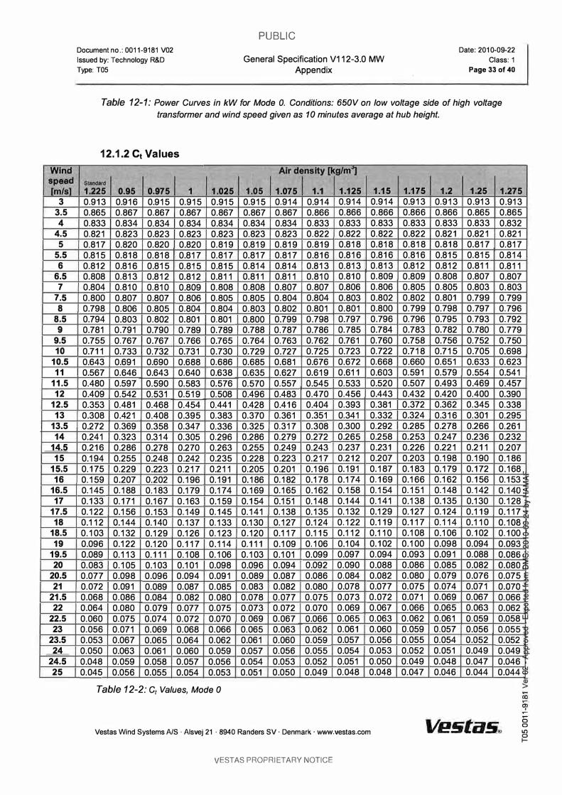
Table 12-1: Power Curves in kW for Mode O. Conditions: 650V on low voltage side of high voltage
transformer and wind speed given as 10 minutes average at hub height.
12.1.2 Ct Values
AJrdensHy[kgJm1 SIaI\d8l'd 1.225 0.95 0.975 1 1.025 1.05 1.075 1.1 1.125 1.15 0.913 0.916 0.915 0.915 0.915 0.915 0.914 0.914 0.914 0.914 0.865 0.867 0.867 0.867 0.867 0.867 0.867 0.866 0.866 0.866 0.833 0.834 0.834 0.834 0.834 0.834 0.834 0.833 0.833 0.833 0.821 0.823 0.823 0.823 0.823 0.823 0.823 0.822 0.822 0.822 0.817 0.820 0.820 0.820 0.819 0.819 0.819 0.819 0.818 0.818 0.815 0.818 0.818 0.817 0.817 0.817 0.817 0.816 0.816 0.816 0.812 0.816 0.815 0.815 0.815 0.814 0.814 0.813 0.813 0.813 0.808 0.813 0.812 0.812 0.811 0.811 0.811 0.810 0.810 0.809 0.804 0.810 0.810 0.809 0.808 0.808 0.807 0.807 0.806 0.806 0.800 0.807 0.807 0.806 0.805 0.805 0.804 0.804 0.803 0.802 0.798 0.806 0.805 0.804 0.804 0.803 0.802 0.801 0.801 0.800 0.794 0.803 0.802 0.801 0.801 0.800 0.799 0.798 0.797 0.796 0.781 0.791 0.790 0.789 0.789 0.788 0.787 0.786 0.785 0.784 0.755 0.767 0.767 0.766 0.765 0.764 0.763 0.762 0.761 0.760 0.711 0.733 0.732 0.731 0.730 0.729 0.727 0.725 0.723 0.722 0.643 0.691 0.690 0.688 0.686 0.685 0.681 0.676 0.672 0.668 0.567 0.646 0.643 0.640 0.638 0.635 0.627 0.619 0.611 0.603 0.480 0.597 0.590 0.583 0.576 0.570 0.557 0.545 0.533 0.520 0.409 0.542 0.531 0.519 0.508 0.496 0.483 0.470 0.456 0.443 0.353 0.481 0.468 0.454 0.441 0.428 0.416 0.404 0.393 0.381 0.308 0.421 0.408 0.395 0.383 0.370 0.361 0.351 0.341 0.332 0.272 0.369 0.358 0.347 0.336 0.325 0.317 0.308 0.300 0.292 0.241 0.323 0.314 0.305 0.296 0.286 0.279 0.272 0.265 0.258 0.216 0.286 0.278 0.270 0.263 0.255 0.249 0.243 0.237 0.231 0.194 0.255 0.248 0.242 0.235 0.228 0.223 0.217 0.212 0.207 0.175 0.229 0.223 0.217 0.211 0.205 0.201 0.196 0.191 0.187 0.159 0.207 0.202 0.196 0.191 0.186 0.182 0.178 0.174 0.169 0.145 0.188 0.183 0.179 0.174 0.169 0.165 0.162 0.158 0.154 0.133 0.171 0.167 0.163 0.159 0.154 0.151 0.148 0.144 0.141 0.122 0.156 0.153 0.149 0.145 0.141 0.138 0.135 0.132 0.129 0.112 0.144 0.140 0.137 0.133 0.130 0.127 0.124 0.122 0.119 0.103 0.132 0.129 0.126 0.123 0.120 0.117 0.115 0.112 0.110 0.096 0.122 0.120 0.117 0.114 0.111 0.109 0.106 0.104 0.102 0.089 0.113 0.111 0.108 0.106 0.103 0.101 0.099 0.097 0.094 0.083 0.105 0.103 0.101 0.098 0.096 0.094 0.092 0.090 0.088 0.077 0.098 0.096 0.094 0.091 0.089 0.087 0.086 0.084 0.082 0.072 0.091 0.089 0.087 0.085 0.083 0.082 0.080 0.078 0.077 0.068 0.086 0.084 0.082 0.080 0.078 0.077 0.075 0.073 0.072 0.064 0.080 0.079 0.077 0.075 0.073 0.072 0.070 0.069 0.067 0.060 0.075 0.074 0.072 0.070 0.069 0.067 0.066 0.065 0.063 0.056 0.071 0.069 0.068 0.066 0.065 0.063 0.062 0.061 0.060 0.053 0.067 0.065 0.064 0.062 0.061 0.060 0.059 0.057 0.056 0.050 0.063 0.061 0.060 0.059 0.057 0.056 0.055 0.054 0.053 0.048 0.059 0.058 0.057 0.056 0.054 0.053 0.052 0.051 0.050 0.045 0.056 0.055 0.054 0.053 0.051 0.050 0.049 0.048 0.048
Table 12-2: Ct Values, Mode 0
Veslas Wind Systems AIS· Aisvej 21 . 8940 Randers SV· Denmark' www.vestas.com
VESTAS PROPRIETARY NOTICE
1.175 1.2 0.913 0.913 0.866 0.866 0.833 0.833 0.822 0.821 0.818 0.818 0.816 0.815 0.812 0.812 0.809 0.808 0.805 0.805 0.802 0.801 0.799 0.798 0.796 0.795 0.783 0.782 0.758 0.756 0.718 0.715 0.660 0.651 0.591 0.579 0.507 0.493 0.432 0.420 0.372 0.362 0.324 0.316 0.285 0.278 0.253 0.247 0.226 0.221 0.203 0.198 0.183 0.179 0.166 0.162 0.151 0.148 0.138 0.135 0.127 0.124 0.117 0.114 0.108 0.106 0.100 0.098 0.093 0.091 0.086 0.085 0.080 0.079 0.075 0.074 0.071 0.069 0.066 0.065 0.062 0.061 0.059 0.057 0.055 0.054 0.052 0.051 0.049 0.048 0.047 0.046
1.25 0.913 0.865 0.833 0.821 0.817 0.815 0.811 0.807 0.803 0.799 0.797 0.793 0.780 0.752 0.705 0.633 0.554 0.469 0.400 0.345 0.301 0.266 0.236 0.211 0.190 0.172 0.156 0.142 0.130 0.119 0.110 0.102 0.094 0.088 0.082 0.076 0.071 0.067 0.063 0.059 0.056 0.052 0.049 0.047 0.044
1.275 0.913 0.865 0.832 0.821 0.817 0.814 0.811 0.807 0.803 0.799 0.796 0.792 0.779 0.750 0.698 0.623 0.541 0.457 0.390 0.338 0.295 0.261 0.232 0.207 0.186 0.168 0.153 � 0.140' 0.128 � 0.117 0.108�� 0.100 c� 0.093�1> 0.086�� 0.08Oe!) 0.075 0.070" 0.066 � 0.062 � 0.058 0.055 � 0.052 0.049 0.046 0.044
<Il >
a a Il) r=

PUBLIC
Document no.: 0011-9181 V02
Issued by: Technology R&D
Type:T05
General Specification V112-3.0 MW Appendix
12.1.3 Noise Levels
Candltici)Os: MeE!.suremertt standard IEC 61400-1 � ed.2 2002 Wlnd shear: 0.16 Max. turbulence at 10 meter height: 16% Inflow angle (vertical): 0 ± 2° Air denslty: 1.225 kg/m3
HubHelght 84m 94m LwA @ 3 mis (10 m above ground) [dBA] 94.7 94.7 Wind speed at hub heiQht [mIs] 4.2 4.3 LwA @ 4 mis (10 m above ground) [dBA] 97.3 97.5 Wind speed at hub helght [mIs] 5.6 5.7 LwA @ 5 mIs (10 m above ground) [dBA] 100.9 101.2 Wind speed at hub height [mIs] 7.0 7.2 LwA @ 6 mis (10 m above ground) [dBA] 104.3 104.5 Wind speed at hub height [mIs] 8.4 8.6 LwA @ 7 mIs (10 m above ground) [dBA] 106.0 106.5 Wind speed at hub height [mIs] 9.8 10.0 LwA @ 8 mis (10 m above ground) [dBA] 106.5 106.5 Wind speed at hub height [mIs] 11.2 11.4 LwA @ 9 mis (10 m above ground) [dBA] 106.5 106.5 Wind speed at hub height [mIs] 12.7 12.9 LwA @ 10 mIs (10 m above ground) [dBA] 106.5 106.5 Wind speed at hub height [mIs] 14.1 14.3 LwA @ 11 mis (10 m above ground) [dBA] 106.5 106.5 Wind speed at hub height [mIs] 15.5 15.7 LwA @ 12 mis (10 m above ground) [dBA] 106.5 106.5 Wind speed at hub height [mIs] 16.9 17.2 LwA @ 13 mIs (10 m above ground) [dBA] 106.5 106.5 Wind speed at hub height [m/s1 18.3 18.6
Table 12-3: Mode 0 Noise Levels at Hub Height
Vestas Wind Systems NS . Aisvej 21 . 8940 Randers SV . Denmark . www.vestas.com
VESTAS PROPRIETARY NOTICE
Date: 2010-09-22 Class: 1
Page 34 of 40
119m 94.7 4.5
98.1 5.9
101.9 7.4
105.1 8.9
106.5 10.4 106.5 11.9
106.5 13.4
106.5 14.9
106.5 16.3
106.5 17.8
106.5 19.3
u. oc:( ::E oc:( :c � � en o 6 o C\I ci? ::E o E ,g '0 � o
� 1
'0 al e c. c. oc:( 1
C\I o
� co .-
� ..-o o Il) r=
GE Energy
Commercial Documentation Wind Turbine Generator Systems 2.5-103 - 50 Hz and 60 Hz
Product Acoustic Specifications
Normal Operation according to IEC 61400-11
(e imagination at work © 2011 GE Company. Ail rights reserved.

GE Energy
Gepower com
Visit us at www gewindenergycom
Ai l technical data is subject to change in li ne with ongoing techn ical development!
Copyright and patent rights
This document is to be treated confidentia l ly. It may only be made accessible to authorized persons. It may
only be made avai lable to th ird parties with the expressed written consent of General Electric Company.
Al i documents are copyrighted within the meaning of the Copyright Act. The transmission and reproduction of
the documents, a lso in extracts, as wei l as the exploitation and communication of the contents are not a l lowed
without express written consent. Contraventions are l iable to prosecution and compensation for damage. We
reserve a i l rights for the exercise of commercial patent rights.
© 2011 General E lectric Company. Al i rights reserved.
GE and . are trademarks and service marks of General Electric Company.
Other company or product names mentioned in this document may be trademarks or registered trademarks of
their respective companies .
•• 1 1. •.
imagination at work 2.5-103_ xx Hz _SCO _ail Corn p _ND _1 ECxxxxxK ENxxx.O 1.doc.
G E Energy product Acoustic Specifications
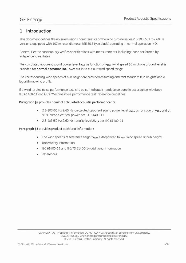
Table of Contents
1 Introduction ........................................................................ ........................................... ,., ............................................... ................... ................. 5 2 2.s�103 Product Normal Operation Acoustic Performance ................... .......................... ............... .. .................... .................... 6 2.1 2.5-103 Normal Operation Calculated Apparent Sound Power Level ....... ,......... ................. . .................... 6 2.2 2.5-103 Normal Operation colculoted Sound Power Level ........ ........................ ........ ............................................................. 6 2.3 2.5�103 Normal Operation Colculoted Tonal Audibility ..................................... ............... ........................................................... 7 3 Product Additionol lnformotion. ................................................................................. . ............................ ........................ ........... 8 3.1 2.5�103 Wind Speeds ot Reference Height Extropoloted to Hub Height................ . ....................... .................... 8 3.2 2.5�103 Testing Uncertointy ond product Variation per IECITS 61400�14 Standard ...................... .......................... 9 3.3 IEe 61400�11 and IECITS 61400�14 Termino(ogy .................................. ......................... .............................................................. 9
CONFIDENTIAL - Proprietary Informotion. DO NOT COP\' without written cansent from GE Company. UNCONTROLLED when printed or transmitted electranÎcally.
© 2011 General Electric Company. Ali rights reserved
l.S·IOL>QCHLSCO_oIlComp_NO_IEOoooooo.EN>oo<.ol.doc.
GE Energy Prod uct Acoustic Specifications
1 1 ntrod uction
This document defines the noise emission characteristics of the wind turbine series 2.5-103, 50 Hz & 60 Hz
versions, equipped with 103 m rotor diameter (GE 50.2 type blade) operating in normal operation (NO).
General Electric continuously verifies specifications with measurements, inc luding those performed by
independent institutes.
The calcu lated apparent sound power level LWA,k as function of VlOm (wind speed 10 m above ground level) is
provided for normal operation (NO) over cut-in to cut out wind speed range.
The corresponding wind speeds at hub height are provided assuming different standard hub heights and a
logarithmic wind profi le .
If a wind turbine noise performance test is to be ca rried out, it needs to be done in accordance with both
I EC 61400-11 and G E's "Machine noise performance test" reference guidel ines.
Paragraph §2 provides nominal calculated acoustic performa nce for:
• 2 .5-103 (50 Hz & 60 Hz) calcu lated apparent sound power level LWA,k as function of Vi0m and at
95 % roted electrical power per I EC 61400-1 1.
• 2.5-103 (50 Hz & 60 Hz) tonolity level �La, k per 1 EC 61400-11
Paragraph §3 provides product additionol information:
• The wind speeds at reference height VlOm extrapolated to VHH (wind speed ot hub height)
• Uncertainty i nformation
• I EC 61400-11 and I EC/TS 6 1400-14 additiono l information
• References
CONFIDENTIAL - Proprietary I nformation. DO NOT COPY without written consent from GE Company. U NCONTROLLED when printed or transmitted electronically.
© 2011 General Electric Company. Ai l rights reserved
2.5-103 _xxHz_SCD _ail Comp_N 0_1 ECxxxxxx.ENxxx.O 1.doc 5/10

GE Energy Product Acou stic Specifications
2 2.5-103 Product Normal Operation Acoustic Performance
2 .1 2.5-103 Normal Operation Ca lcu lated Apparent Sou nd Power Level
The Table 1 provides nominal acoustic specifications for 2.5-103 equipped with 103 m rotor d iameter (GE 50.2
type bladel and 100 m hub height as function of wind speed VlOm (reference wind speed 10 m above ground
levell. operating at normal operation (NO) per I EC 6 1400-11 standard and G E's "Machine noise performance
test" reference guidel ines:
LWA,k* Wind speed at V10m [mIs] Apparent sound power level
[dB]
5 :;:; 96.8
5.5 :;:; 99.5
6 :;:; 101.9
6.5 :;:; 103.8
7 :;:; 105.0
8 :;:; 105.0
9 :;:; 105.0
10- eut out :;:; 105.0
Table 1: Normal operations. 2.5-103 wind turbine, 50.2 m blades 1 103 m rotorl, 100 m hub height. apparent sound power level at wind speed VIOm.
At wind speeds lower than 5 mis the sound power levels decreases, and may get sa low that the wind turbine
noise becomes indistinguishable from the background noise. For a conservative calculation the data at 5 mis may be used.
At wind speeds above 10 mis turbine has reached rated power and the increasing pitch ang le decreases the
noise level. For a conservative calcu lation the data at 10 mis may be used.
2.2 2.5-103 Normal Operation Ca lcu lated Sou nd Power Level
The nominal acoustic performances for 2.5-103, 50 Hz & 60 Hz versions, equipped with 103 m rotor diameter (GE 50.2 type blade) operating in normal operation ( NOl. specified at 95% rated electrica l
power:
• The calculated apparent sound power level is LWA,k � 105.0 dB .
• LWA,k indicates apparent sound power level per I EC 61400-1 1 sta ndard, measured in dB, A-weighted 10 base logarith mic va lue of apparent sound power relative to reference sound power of 10-12 w.
6/10
CONFI DENTIAL - Praprietary Information. DO NOT COPY without written consent from GE Company. U NCONTROLLED when printed or transmitted electranically.
© 201 1 General Electric Company. Ail rights reserved

G E Energy Product Acoustic Specifications
2.3 2.5-103 Normal Operation Calculated Tonal Audibility
The nominal acoustic performances for 2.5-103, 50 Hz & 60 Hz versions. equipped with 103 m rotor
diometer (GE 50.2 type bladel operating in normal operation (NOL specified ot reference ground
measuring distance Ro measurement point #1 per bath IEC 61400-11 and GE's "Mochine noise
performance test" reference guidelines:
• Tonal audibility ÔLa,k < 4 dB.
CQNFIDtNTIAl - ProprÎetory Information. 00 NOT COPVwithout written consent from GE Company. UNCONTROLLED when printed or tronsmitted electronicolly.
(1 2011 General Electric Company. Ail rights reserved
1.5-103�SCO_allCompJ«l_IEClooooo<..ENKIO<.OLdoc 7110

GE Energy Product Acoustic S pecifications
3 Product Add itiona l l nformation
3.1 2.5-103 Wind Speeds at Reference Height Extrapolated to H u b Height
The wind speeds VIOm at reference height ( 10 m above groundl can be extrapolated from VlOm to VHH (wind
speed at hub heightl, per I EC 61400-01, assuming surface roughness of ZO.rel = 0.05 m typical average condition
and using:
In( lom� J _ v: .1 -Oro[
�Om heiglu - kub ( ) lu hub heigh;/ / ZOT�
Meaning wind speeds from Table 1 can be extrapolated to 100 m hub height using VHH = VlOm * 1.43 and to
85 m hub height using VHH = VlOm * 1.40 per Table 2.
Wlnd speed at 10 lTl Wlnd speed at 100 m Wind speed ot 85 m hub
reference height VlOm hub height VI-IHcl00m height VHH..eSm (mIs)
[mIs) [mIs)
� 5.0 � 7.2 � 7.0
5.5 7.9 7.7
6.0 8.6 8.4
6.5 9.3 9.1
7.0 10.0 9.8
8.0 11.5 11.2
9.0 12.9 12.6
� 10.0 � 14.3 � 14.0
Table 2: Relation between wind speed at reference height VlOm and wind speeds at different hub heights VHH for ZO.ref= 0.05 m
l n case that sound power levels are required for integer wind speeds VHH at hub height. the data given in
Table 1 m ust be interpolated for the required wind speeds, using the wind speed conversion rules given in this
clause.
ln case that sound power levels are required for VlOm standard ized wind speed at 10 m height. but for turbines
with other hub height thon given i n Table l, the wind speed data first can be transferred from 10 m height to the referenced hub height in Table 1. Then the wind speed data can be transferred from the desired hub height
bock to 10 m reference height, using the wind speed conversion rules g iven in this clause. The corresponding
sound power level data should be interpolated to meet the desired wind speed values.
8/10
CONFI DENTIAL - Proprietary I nformation. DO NOT COPY without written consent from GE Company. U NCONTROLLED when printed or transmitted electronical ly.
© 2011 General Electric Company. Ail rights reserved
GE Energy Prod uct Acoustic Specifications
3.2 2.5-103 Testing Uncerta inty a nd Product Variation per 1 EC/TS 6 1400-14 Sta nda rd
Per I EC/TS 61400-14, LWAd is the maximum apparent sound power level resulting from n measurements
performed accord ing to I EC 61400-1 1 standard for 95 % confidence level: LWAd= L WA + K, where LWA is the
mean apparent sound power level from n I EC 61400-11 testing reports and K = 1,645 ' O"l.
The testing standard deviation va lues O"l, O"R and O"P for measured apparent sound power level are described
by I EC/TS 61400-14 where O"l is the total standard deviation, O"p is the standard deviation for product variation
and O" R i s the standard deviation for test reproducibi l ity.
Assuming O"R < 0.8 dB and O"p < 0.8 dB typical va lues, leads to calculated K < 2 dB for 95 % confidence level.
3.3 I EC 61400-11 and 1 EC/TS 6 1400-14 Terminology
• LWA,k is wind turbine apparent sound power level ( referenced to 1-12 W) measured with A
weighting os function of reference wind speed VlOm. Derived from mu ltiple measurement
reports per I EC 61400-1 1, it is considered as a mean value.
• O"p is the product variation i.e. the 2.5-103 un it-to-unit product variation: typically < 0.8 d B
• O"R is the overa l l measurement testing reproducibi l ity as defined per I EC 6 1400-11 ; typica l ly
< 0.8 dB with adequate measurement conditions and sufficient amount of dota samples
• O"l is the total standard deviation combining both O"p and O"R • K = 1,645 . O"l is defined by I EC/TS 61400-14 for 95 % confidence level
• Ra is the ground measuring distance from the wind turbine tower axis per I EC 61400-1 1
• �La,k is the tonal audibi l ity according to 1 EC 6 1400-11 , described as potentia l ly audible narrow
band sound
CONFI DENTIAL - Proprietary Information. DO NOT COPY without written consent from GE Company. UNCONTROLLED when printed or transmitted electronically.
© 2011 General Electric Company. Ai l rights reserved
9/10
G E Energy Product Acaustic Specifications
References:
10/10
• IEC 61400-1, Wind turbines - part 1: Design requirements. ed. 3, 2005-08
• IEC 61400-11, wind turbine generotor systems port 11: Acoustic noise measurement
techniques, ed. 2.1. 2006-11
• IECITS 61400-14, Wind turbines - port 14: Declaration of apparent sound power level and
tonality volues, ed. 1, 2005-03
• MNPT - Machine Noise Performance Test. Technical Documentation, GE 2007
CONFIDENTIAl - Proprietory Information. 00 NOT COPV without writlen consent from GE Company. UNCONTROlLEO when printed or tfOnsmitted electronicolly.
e 2011 General Electric Company. Ail rights reserved
2.S-103_xxli�O_ollComp_NO_jEûoooooc.EN><X><.Ol ,doc

GE Energy
Commercial Documentation Wind Turbine Generator Systems 2.75-103 - 50 Hz and 60 Hz
Product Acoustic Specifications
Normal Operation according to I EC 61400-11
(fj) imagination at work © 2010 GE Company. Ail rights reserved.

GE Energy
Gepo\Y�r.com Vi5., u� Cl www.gewindenergycom
Ai l technical data is subject to change in l ine with ongoing technical development!
Copyright and patent rights
This document is to be treated confidential ly. It may only be made accessib le to authorized persons. It may
only be made avai lable to third parties with the expressed written consent of General Electric Company.
Ail documents are copyrighted with in the meaning of the Copyright Act. The transmission and reproduction of
the documents, a lso in extracts, as wei l as the exploitation and communication of the contents are not a l lowed
without express written consent. Contraventions are l iab le to prosecution and compensation for damage. We
reserve 0 1 1 rights for the exercise of commercial patent rights.
© 2010 Genera l Electric Com pany. Ail rights reserved.
GE and . are trademarks a nd service marks of General Electric Company.
Other company or product nomes mentioned in this document may be trademarks or registered trademarks of
their respective companies.
8) imaginat ion at work 2 75-103_xxHz_SCD _oIlComp_NOJ ECxxxxxx.ENxxx.OO.doc.
G E Energy Product Acoustic Specifications
Table of Contents
1 Introduction ...... ........................................................................................................... ....................... ................................................................... 5 2 2.75-103 Product Normal Operation Acoustic Performance .... ..................................................................................................... 6 2.1 2.75-103 Normal Operation Colculoted Apparent Sound Power Level ....................... .................. . ............... 6 2.2 2.75-103 Normal Operation Colculated Tonolity .................. ............................... .......................................................................... 7 3 2.75-103 Product Aodditionol lnformotion.................... . ............................................................................................................. 8 3.1 2.75-103 Wind Speeds ot Reference Height extropoloted ta Hub Height. ......................................................................... 8 3.2 2.75-103 Testing Uncertointy and Praduct Variation per lEC/TS 61400-14 Standard .................. ............ 8 3.3 IEC 61400-11 and IEC 61400-14/TS Terminology ...................................... ................................ ................................. 9
CONFIDENTIAL - Proprietory Informotion. DO NOT COPY without written consent from GE Compony. UNCONTROLlED when printed or tronsmitted electronicolly.
Cl 2010 General Electric Compony. Ali rights reserved
2.?S·IOJ..)U<l1z_SCD_oltCornp_NO-.lfOooou<>t.EN><><><.OO.dot:
GE Energy Prod uct Acoustic Specifications
1 I ntroduction
This document defines the noise emission characteristics of the wind turbine series 2 .75-103 , 50 Hz and 60 Hz versions, equipped with 103 m rotor diameter (G E 50.2 type blade) operating in normal operation (NO).
General Electric continuously verifies specifications with measurements, incl uding those performed by
independent institutes.
The calculated apparent sound power level LwA,k as function of VlOm (reference wind speed 10 m above ground
level) is provided for normal operation (NO) over eut- in to eut-out wind speed range.
The corresponding wind speeds at hub height VHH are provided assuming different standard hub heig hts and a
logarithmic wind profile.
I f a wind turbine noise performance test is to be ca rried out, it needs to be do ne in accordance with both
I EC 6 1400-1 1 and G E's "Machine noise performance test" reference guidel ines.
Paragraph §2 provides nominal calcu lated acoustic performa nce for:
• 2.75-103 (50 & 60 Hz) calcu lated apparent sound power level LwA,k as function of VlOm and at
95% rated electrica l power per I EC 6 1400-11.
• 2.75-103 (50 & 60 Hz) tona l ity level ALa, k per 1 EC 6 1400-1 1
Paragra ph § 3 provides 2.75-103 acoustic performances additional data:
• The wind speeds at reference height VlOm extrapolated to VHH (wind speed at hub height)
• Uncertainty i nformation
• I EC 61400-1 1 and 1 EC/TS 6 1400-14 additiona l information
CONFIDENTIAL - Proprietary Information. DO NOT COPY without written consent from GE Company. UNCONTROLLED when printed or transmitted electronically.
© 2010 General Electric Company. Ail rights reserved
2.75-103_xxHz_SCD_oIIComp_NOJ ECxxxxxx. ENxxx.OO.doc 5/10

GE Energy Product Acoustic Specifications
2 2.75-103 Product Normal Operation Acoustic Performance
2.1 2 .75-103 Normal Operation Ca lcu lated Appa rent Sound Power Level
The Table 1 provides nominal acoustic specifications for 2.75-1 03 equipped with 1 03 m rotor diameter
(GE 50.2 type blade) and 1 00 m hub height as function of wind speed V10m (reference wind speed 1 0 m
above ground level), operating at normal operation (NO) per IEe 61 400-1 1 standard and GE's "Machine
noise performance test" reference guidelines:
LWA,k· Wlnd speed at VIam (m/s) Apparent sound power level
(dB)
:-:; 5 :-:; 97.1
6 :-:; 102.2
6.5 :-:; 104.4
7 :-:; 105.0
8 :-:; 105.0
� 9 :,; 105.0
Table 1: Normal operations, 2.75-103 wind turbine, 50.2 m blades 1 103 m rotor), 100 m hub height, apparent sound power level at wind speed VIOm.
At wind speeds lower than 5 mis the sound power levels decreases, and may get 50 low that the wind turbine
noise becomes ind istinguishable from the background noise. For a conservative calculation the data at 5 mis
may be used.
At wind speeds above 9 mis turbine has reached rated power and the increasing pitch angle decreases the
noise level. For a conservative calcu lation the data at 9 mis may be used.
The nominal acoustic performances for 2.75-1 03, 50 Hz and 60 Hz versions, equipped with 1 03 m
rotor d iameter (GE 50.2 type blade) operating in normal operation (NO), specified at 95 % rated
electrical power:
• The calculated apparent sound power level is LWA.k S 105.0d BA.
* LWA.k indicates apparent sound power level per IEC-61�00-11 standard measured in dB, A-weighted 10 base logorithmic value 01 apparent sound power relative to relerence sound power of 10.12 W.
6/10
CONFI DENTIAL - Proprietary I nformation. DO NOT COPY without written consent from GE Company. UNCONTROLLED when printed or transmitted electronically.
© 2010 General Electric Company. Ail rights reserved
2 75-103_xxHz_SCD_aIlComp_NOJ ECxxxxxx.ENXxx.00.doc
G E Energy Product Acoustic Specifications
2.2 2.75-103 Normal Operation Ca lculated Tona l ity
The nominal ocoustic performance for 2.75-103. 50 Hz and 60 Hz versions, equ ipped wlth 103 m rotor
d iometer (GE 50.2 type blodel operoting in normal operation (NOL specified ot reference ground
meosuring d istonee Ra meosurement position #1 per bath I EC 61400-1 1 and GE's "Machine noise
performance test" reference guide l ines:
• Tonal oudibU ity Ale, k < 4 dB.
CONFIDENTIAl - Proprietary I nformation. DO NOT COPV without written consenl From GE Company. UNCONTROLLEDwhen printed or transmitted electronicolly.
© 20 10 General Electric Company. Al i rights reserved 2.7S-103.;od-lz_SCD_oIIComp_NOJEDIx:<)()<)<,EN)(J<)(.OO.doc 7/10
GE Energy Product Acoustic Specifications
3 2.75-103 Product Add itiona l l nformation
3.1 2.75-103 Wind Speeds at Reference Height extra polated to H u b Heig ht
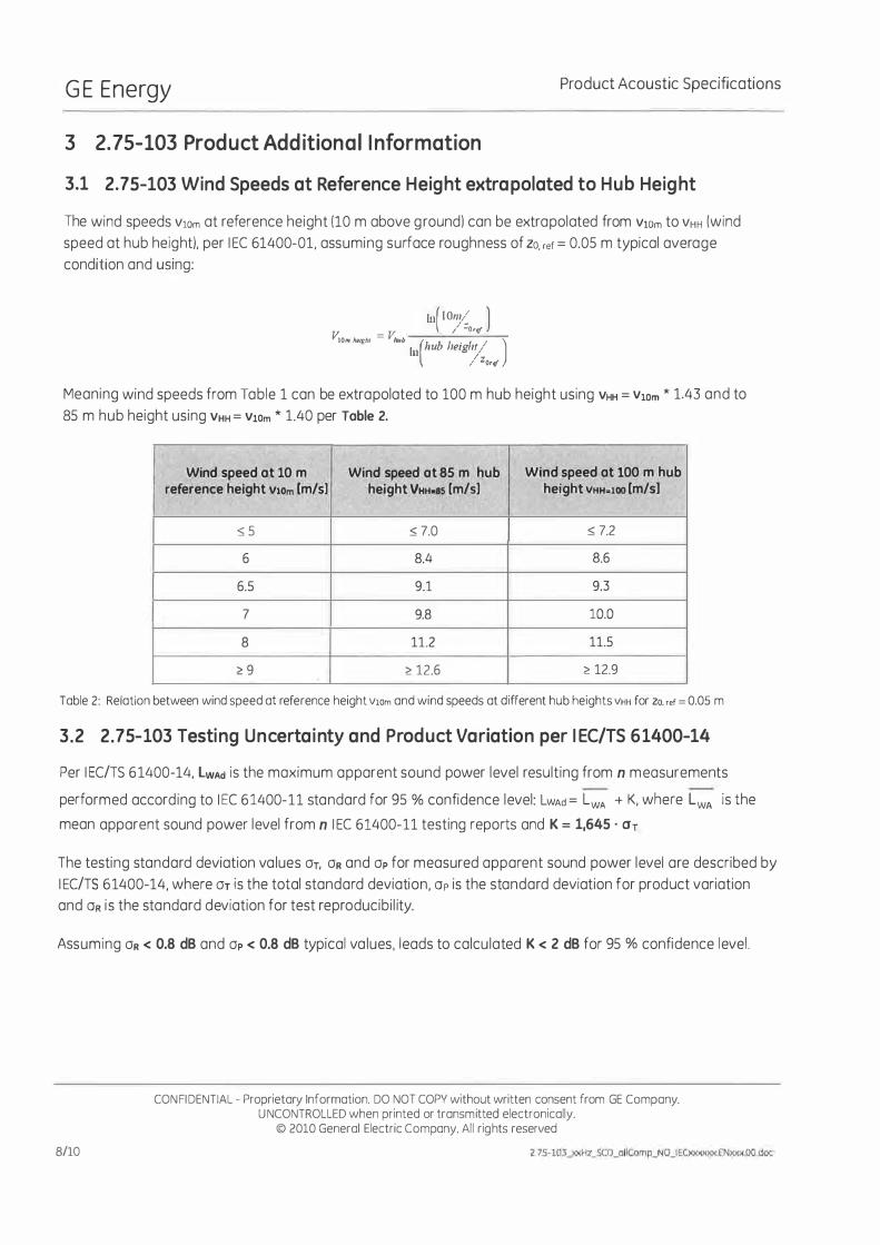
The wind speeds V10m at reference height (10 m above g roundl can be extrapolated from VlOm to VHH (wind
speed at hub heightl. per 1 EC 61400-01, assuming surface roughness of ZO. ref = 0.05 m typical average
condition and using:
lu( IOI�� ) v: = v: / ·0'<1
IO., h'iglll hub (h b 1 . 1 / ) hl U lelg 'j / zOr�
Meaning wind speeds from Table 1 can be extrapolated to 100 m hub height using VHH = V10m * 1.43 and to
85 m hub height using VHH = V10m * 1.40 per Table 2.
Wind speed at 10 m Wlnd speed at 85 m hub Wind speed at 100 m hub reference height Vi0m (mIs) helght VHHtS5 (m/s1 height VHH=l00 (mIs)
:S 5 :s 7.0 :s 7.2
6 8.4 8.6
6.5 9.1 9.3
7 9.8 10.0
8 11.2 11.5
� 9 � 12.6 � 12.9
Table 2: Relation between wind speed at reference height V10m and wind speeds at different hub heights VHH for ZOo ref = 0.05 m
3.2 2.75-103 Testing Uncerta inty and Product Variation per 1 EC/TS 6 1400-14
Per 1 EC/TS 6 1400-14, lWAd is the maximum apparent sound power level result ing from n m easurements
performed accord ing to I EC 6 1400-11 standard for 95 % confidence level: LWAd = LWA + K, where LWA is the
mean apparent sound power level from n I EC 61400-11 testing reports and K = 1,645 ' Or
The testing standard deviation va lues Or, OR and Op for measured apparent sound power level are described by
1 EC/TS 6 1400-14, where Or is the total standard deviation, Op is the standard deviation for product variation
and OR is the standard deviation for test reproducibi l ity.
Assuming OR < 0.8 dB and Op < 0.8 dB typical va lues , leads to calcu lated K < 2 dB for 95 % confidence level.
8/10
CON FI DENTIAL - Proprietary Information. DO NOT COPV without written consent from GE Company. U NCONTROLLED when printed or transmitted electronically.
© 2010 General Electric Company. Ail rights reserved

GE Energy Product Acoustic Specifications
3.3 I EC 61400-11 and I EC/TS 61400-14 Term inology
• LWA,K is wind turbine apparent sound power level (referenced to 10-12W) measured with A
weighting as function of reference wind speed VlOm. Oerived from multiple measurement
reports per I EC 61400-11, it is considered as a mean va lue
• Op is the product variation i .e. the 2.75-103 unit-to-unit product variation; typica l ly < 0 .8d B
• OR is the overa l l measurement testi ng reproducibi l ity as defined per I EC 61400-11 ; typical ly
< 1dB with adequate measurement conditions and sufficient amount of data samples
• OT is the total standard deviation combining both Op and OR • K = 1,645 . OT is defined per I EC/TS 61400-14 for 95 % confidence level
• Re is the ground measuring distance from the wind turbine tower axis per I EC 61400-11
• L1La, k iS the audibi l ity according to I EC 61400-11, described as potentia l ly audib le narrow band
sound
CONFIDENTIAL - Proprietary Information. DO NOT COPI( without written consent from G E Company. U NCONTROLLED when printed or transmitted electronically.
© 2010 General Electric Company. Ai l rights reserved
9/10

G E Energy Product Acoustic Specifications
References:
10/10
• IEC 61400*1. Wind turbines - part 1: Design requirements, ed. 3, 2005-08
• IEe 61400-11. wind turbine generotor systems port 11: Acoustic noise measurement
techniques. ed. 2.1, 2006-11
• IEC/TS 61400-14. Wind turbines - port 14: Declaration of apparent sound power leve! and
tonolity values, ed. 1. 2005-03
• MNPT - Machine Noise Performance Test. Technicol documentation, GE 2007
CQNF1DENTIAL - Proprietory Information. DO NOT COP'!' without written consent rrom GE Company. UNCONTROllED when printed or tronsmitted electronicolly.
e 2010 General Electric Compony. Ali rights reserved
17S·103Jl<Hl�o_ulICornp_NO_IEûooooot.EN""""OO,doI;