Embed Size (px)
Citation preview
Page 1 of 48
Annexure-I Specification of Rail Grinding Machine
1. General
1.1. These specifications provide the technical requirements for the manufacture, supply, testing,
commissioning, maintenance and operation of a self-propelled rail-grinding machine of
minimum 72 stones module (here after referred as machines) for use on the tracks of Indian
Railways. The Rail Grinding Machine to be supplied is meant for grinding the rails in
corrective mode and preventive mode, to improve the worn profile of rail head, rail wheel
contact band, its location, to remove fatigued material having micro cracks and other surface
defects on the rail head and remove corrugations. The Rail Grinding Machine shall be able to
effectively grind track on Indian Railways. The consist of RGM shall include two rest vans
and one water wagon. The supplier shall furnish, deliver, warrant, maintain and operate the
Rail-Grinding Machines as per these specifications and tender conditions.
1.2. The Technical Specifications have been drafted to cover the performance and quality
requirement of the equipment. Tenderers are requested to carefully study the specifications
and assure that their equipment fully comply with these specifications. Thereafter, if a
tenderer feels that his equipment can substantially meet the performance and quality
requirement of the specification in general but does not fully satisfy a particular
specification, he should immediately seek clarification from the purchaser prior to
submission of bids as to whether such deviation is substantive or not. Whenever there are
any such deviation(s), tenderer should mention the same in the statement of deviation from
the specification to be submitted along with bid and should clarify how his equipment will
meet the functional requirement of such clause.
1.3. The tenderer shall specify the model offered and furnish a detailed Technical Description of
the same. System/sub-systems of the working mechanisms of the Rail Grinding Machine as
per para’3 of this specification &Annexure and all the items of the specifications in general
shall be described in detail in the “Technical Description”, along with the sketches to show
the manner in which the requirement of the specifications are accomplished by the machines
(models) offered.
1.4. Photographs and video (in compact disc//Pen drive) of the type of machine offered in
working mode (showing the working of machine in real time under field conditions) be
enclosed with the offer. This shall also show close-ups of various working
assemblies/systems and the full machine. Tenderer shall also submit the names of countries
& Railways where the offered machines are working and their working can be seen if felt
necessary by the purchaser.
2. Dimensional and Operating requirements:
2.1. The diesel-powered self-propelled Rail-Grinding Machine shall be robust, reliable and
suitable for working on Indian Railways. The design and dimensions of the machine
components shall be to SI (International) System of Units standards and also comply with
provision of Indian Railways BG schedule of Dimensions-2004 incorporating all correction
slips issued .Quality assurance during manufacturing of the machine shall be according to

Page 2 of 48
ISO-9001.The welding standard followed for manufacturing of machine should be to
ISO:3834, EN:15085 or any other equivalent standard. The manufacturer should specify the
standard followed and certify that it meets the welding standard mentioned above.
2.2. The Rail Grinding Machine shall be Diesel powered (preferably indigenous) self-propelled
bogie type vehicle(s) with minimum 4 axles (2 bogies) for each vehicle. It should be reliable
and suitable for working on Indian Railway’s straight, transitions and curved track up to 10º
curves on broad gauge (1676 mm). Shared 2 axle bogies between two grinding cars and/or
between two grinding buggies/carriages are not acceptable.
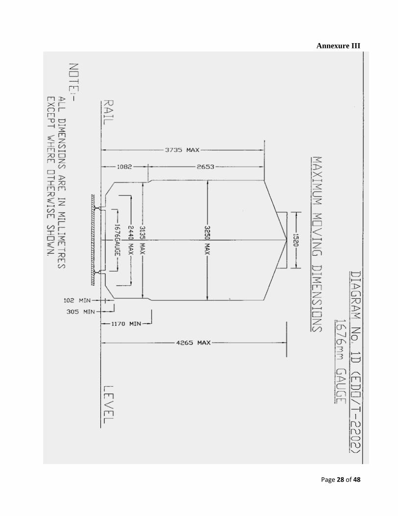
2.3. The profile of the on-track machines longitudinally and in cross section during transfer as
self-propelled vehicle or towed in train formation shall be within the Indian Railways
standard metric BG schedule of Dimensions-2004 incorporating all correction slips up to
date. The minimum and maximum moving dimensions are enclosed in Annexure-III. The
tenderer shall provide sketches of the machines in plan and cross-section and shall give
calculations to show the extent of lateral shift at the ends, centre and any other relevant cross
section and to prove that the machines do not cause infringement while moving on a 10°
curve at any cross section.
2.4. Where an infringement to Indian Railways Standard BG Schedule of Dimensions (metric)-
2004 incorporating all correction slips up to date is considered necessary by the
manufacturer as intrinsic to the design of the machine for meeting the work performance
requirements laid down in this specification while meeting the safety and operational
requirements of IR, the same shall be done with the prior approval of the Purchaser and
decision of the Purchaser in permitting any such infringement shall be final and binding on
the manufacturer. Tenderers may note that acceptance of any such deviation during
consideration of preliminary design details in the offer is only in principle acceptance and
the final decision will be taken by the Purchaser at the stage of consideration of machine
design for issuing speed certificate. In the past, IR have condoned certain infringements to
such dimensions as Rigid wheel Base, Length of stocks, Distance apart of bogie centres and
maximum height of floor above Rail level in certain track machines after due consideration
of their design features vis-à-vis safety and operational requirements of IR. However,
condonation of an infringement in another track machine in the past does not by itself entitle
the manufacturer to assume acceptance of the same in other track machines by IR.
2.5. Adequate clearance shall be allowed so that no component infringes the Minimum clearance
of 102 mm from rail level while travelling.
2.6. Wherever applicable, axle load shall be less than 20.32 T with minimum axle spacing of
1.83m. Load per meter shall not exceed 7.67 tones. Axle loads up to 22.82t and lower axle
spacing may be permitted, provided the load combinations do not cause excessive stresses in
the track and bridges of IR. Further at the stage of consideration on machine design for
issuing speed certificate, stresses in the track and bridges shall be calculated by IR/RDSO
based on design data submitted by the firm as per Annexure–VIII A,B&C and decision of
IR/RDSO shall be final in this regards.
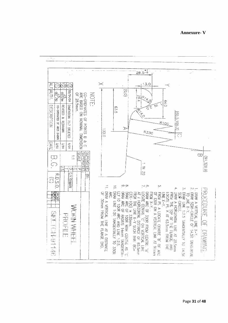
2.7. The Machines shall have a desirable wheel diameter of 914mm or more (new wheel profile).
However, lesser diameter up to 760 mm for Rail Grinding machine can be permitted
provided it meets the condition laid down in clause 2.5 at its condemnation limit as per
design and provided the rail wheel contact stresses for 72 UTS rails are within permissible
Page 3 of 48
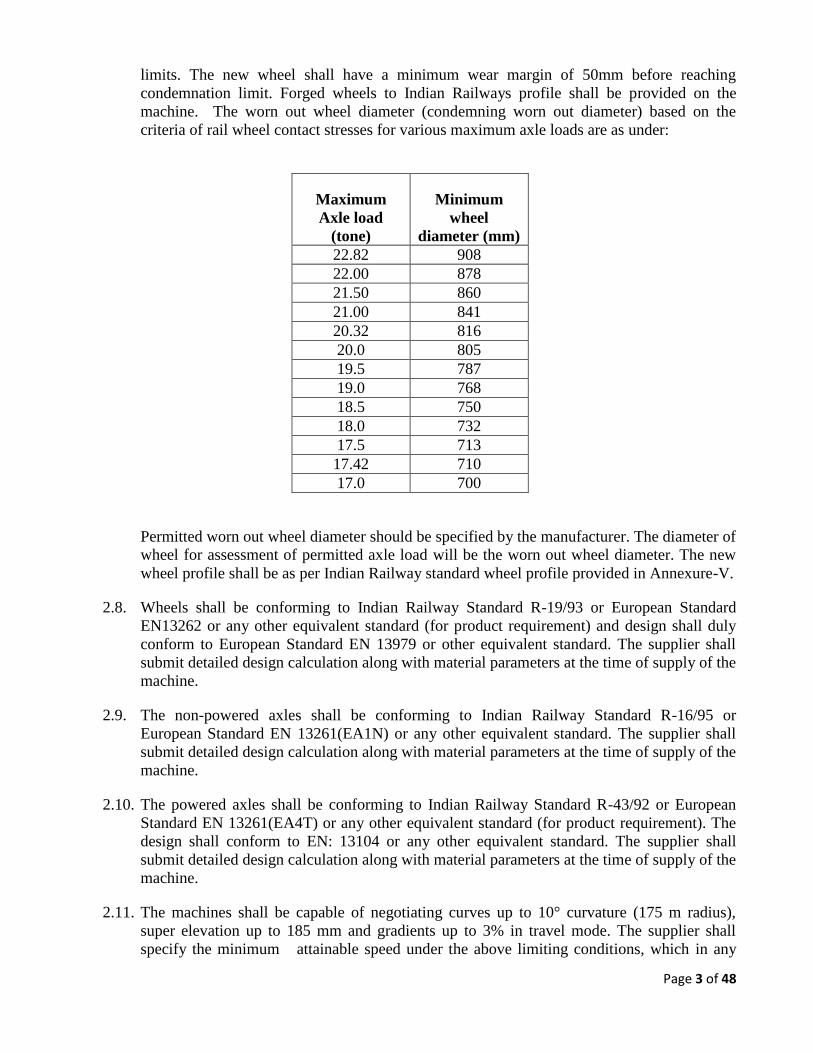
limits. The new wheel shall have a minimum wear margin of 50mm before reaching
condemnation limit. Forged wheels to Indian Railways profile shall be provided on the
machine. The worn out wheel diameter (condemning worn out diameter) based on the
criteria of rail wheel contact stresses for various maximum axle loads are as under:
Maximum
Axle load
(tone)
Minimum
wheel
diameter (mm)
22.82 908
22.00 878
21.50 860
21.00 841
20.32 816
20.0 805
19.5 787
19.0 768
18.5 750
18.0 732
17.5 713
17.42 710
17.0 700
Permitted worn out wheel diameter should be specified by the manufacturer. The diameter of
wheel for assessment of permitted axle load will be the worn out wheel diameter. The new
wheel profile shall be as per Indian Railway standard wheel profile provided in Annexure-V.
2.8. Wheels shall be conforming to Indian Railway Standard R-19/93 or European Standard
EN13262 or any other equivalent standard (for product requirement) and design shall duly
conform to European Standard EN 13979 or other equivalent standard. The supplier shall
submit detailed design calculation along with material parameters at the time of supply of the
machine.
2.9. The non-powered axles shall be conforming to Indian Railway Standard R-16/95 or
European Standard EN 13261(EA1N) or any other equivalent standard. The supplier shall
submit detailed design calculation along with material parameters at the time of supply of the
machine.
2.10. The powered axles shall be conforming to Indian Railway Standard R-43/92 or European
Standard EN 13261(EA4T) or any other equivalent standard (for product requirement). The
design shall conform to EN: 13104 or any other equivalent standard. The supplier shall
submit detailed design calculation along with material parameters at the time of supply of the
machine.
2.11. The machines shall be capable of negotiating curves up to 10° curvature (175 m radius),
super elevation up to 185 mm and gradients up to 3% in travel mode. The supplier shall
specify the minimum attainable speed under the above limiting conditions, which in any
Page 4 of 48
case shall not be less than 25 kmph. Water wagon and camping coaches shall be considered
as part of consist/formation while travelling up to 3 % gradient.
2.12. The machines shall be capable of continuous operation during the varying atmospheric and
climatic conditions occurring throughout the year in India. The range of climatic conditions
is as follows:
Ambient temperature : -5° to 55°C
Altitude : Sea level to1800 m
Humidity : 20% to 100%
Maximum rail temperature : 70°C
All the system components on the machine shall be covered by roof or other suitable sturdy
covering so that the system & components vulnerable to moisture ingress are not adversely
affected during rains and the machine is able to work continuously even during rains
2.13. The Rail Grinding Machine in consist/formation (in composition with all its integral part)
shall be capable of travelling at a speed of 80 km/h in either direction when travelling on its
own power. In train formation, it should be capable of being hauled at a speed of 100 km/h.
It shall be possible to haul the machines in both directions at the same speed. Since the
machines are likely to cover long distances on their own power, the travel drive system
should be robust to sustain these requirements during the life of the machine without much
break down/failure.
2.14. The machines shall be capable of working without requiring power block in electrified
sections. 25KV or 2x25 KV AC power supply is used for traction through an overhead wire
at 5.5 m above rail level. On bridges and tunnels, the height is restricted to 4.8 m. The
accuracy of measurement by measuring equipments/systems of the machine shall not be
affected in any manner due to overhead electricity and also due to track circuit voltage (12 V
& 1 AMP).
2.15. The machines and any of its parts shall not infringe the adjoining track as per ‘BG Schedule
of dimensions of Indian Railways (metric)-2004 print with latest corrigendum and up to date
correction slips issued while opening and closing of work. The machine shall be equipped
with pneumatically operated brake blocks acting on all wheels.
2.16. In the work mode, no part of the machines should rise beyond 4.265 m. above rail level for
safe working in the electrified sections.
2.17. While working on double line sections, the machines shall not infringe the adjoining track
and it shall be possible to permit trains at full speed on that track. Minimum spacing of track
is 4.265m.
3. WORKING MECHANISM OF RAIL GRINDING MACHINE
3.1. The working mechanism of the rail grinding machine shall be equipped with:
Page 5 of 48
3.1.1. Rail grinding mechanism
3.1.2. Control system for rail grinding mechanism
3.1.3. Optical rail profile measurement system and its transfer to onboard computer
3.2. The rail grinding machine should be capable of producing good longitudinal profile of the
railhead continuously.
3.3. The rail grinding machine should be capable of grinding operations on plain track and
curves, track in tunnels, track on bridges having guard rails without removing the guard
rails, and track on platform lines. It should also be capable of grinding operations on track
on level crossings having check rails and curves with check rails with or without removing
check rails. Maximum grind speed should not be less than 18 kmph on plain track.
3.4. The rail grinding machine shall also be capable of grinding, if required, only one of the
rails of the track as in the case of curves.
3.5. The rail grinding machine shall be capable of grinding profile of UIC 60 Kg rail section, 52
Kg rail heads in 72/90/110 UTS strength and Head Hardened rails inclusive of fish plated
joint, insulated joints and welded joints in long welded rails and short welded rails laid on
pre stressed concrete sleepers, steel sleepers, composite sleepers and wooden sleepers. It
shall also function effectively on rails having surface defects such as wheel burns, shelling
etc. The number of grinding stones and grinding units of the machine shall be such as to
carry out controlled grinding of all rail corrugation defects and also defects of long wave
length to produce a smooth cross sectional profile without creating any sharp edge between
the rail table and gauge face.
3.6. The supplier shall ensure that the offered rail grinding machines shall be capable of
modular up gradation at a later stage and shall have such computer hardware and software
which shall facilitate easy up gradation.
3.7. The rail grinding mechanism should be electric driven, drawing power from an on-board
diesel generating set.
3.8. All the components of the rail grinding machine must be robust and capable of continuous
operation upto 8 hrs in one spell under the field working conditions. They must be
shielded against heavy heat accumulation in the work area and metallic dust generated at
the work site.
3.9. To achieve the target profile with smooth curvatures, with minimum points of singularities,
the Rail grinding machine shall have a minimum of 72 grinding stones (36 per rail), which
can be configured in various configurations to achieve different target profiles.
3.10. Each grinding module shall be controlled by a hydraulic/pneumatic cylinder for its
up/down movement.
3.11. The rail grinding machine shall be equipped with an inbuilt mechanism to stop the grinding
and lift the grinding stones/carriages when the operating speed falls below a certain
Page 6 of 48
minimum speed to avoid metallurgical damage due to heat accumulation. The minimum
speed, at which the grinding shall stop automatically, shall be as per supplier's design but it
shall be mentioned in the offer.
3.12. Each grinding module shall comprise of a ring shaped stone and a grinding motor with
suitable positioning mechanism to control the stone position, to achieve the target profile
by the various grinding module configurations. Firm shall submit their module
arrangement, Configuration should have a fully adjustable angle range of +70 degrees to
gauge and -20 degrees to field, independently controlled from the operator station in the
cab Each grinding motor spindle angle shall be accurate within ±0.25° (plus/minus one
quarter of a degree) of the designed spindle axis positioning angle. Each module shall
contain one or more grinding motors with, independent tilt cylinder for each module and
must have the capability of being positioned by the control system independent of any
other grinding module. In each module grind motor/tilt cylinder should be separated by
certain angle so that heating or other impact does not take place on rail. The tilting
cylinders should not be shared with adjacent modules and must be independent for each
module.
3.13. At the work location, the prevailing temperature may be higher than the specified
maximum temperature of 55oC. The peak load on the grinding motors, under the most
demanding conditions shall not be more than 80% of the continuous load rating of the
motor, at the prevailing temperature conditions. The supplier shall furnish the peak load
for the motors at various locations and the continuous load ratings of the motors under the
operating conditions, as per the manufacturer’s catalogues.
3.14. The grinding motor power shall be as per the supplier’s design to achieve the output
parameters laid down below and may vary with the total number of grinding motors
provided on the rail grinding machine (not less than 72). However, the total grinding
power provided on the rail grinding machine (number of motors x continuous load rating of
each motor) shall not be less than 2000HP.
3.15. The rail grinding machine shall be capable of removing, a minimum of 20 sq. mm material
from each rail(40 sq. mm for both the rails) per pass, from the rail top of a 60 kg. UIC (90
UTS) rail section, with top surface work hardened to BHN 315 to 380, while operating at a
speed of 15 kmph. While assessing the rail grinding machines performance, the test rail
profile (after grinding) shall be close to the target profile and the metal removal shall be
fairly uniform over the entire rail surface to be ground.
3.16. The capacity of rail grinding machine regarding depth of grinding per pass, for 60 kg 90
UTS work hardened rail top while grinding uniformly over full width and gauge faces at
various working speeds, shall not be less than as mentioned below :
18 kmph : 0. 13mm
15 kmph : 0. 20 mm
3.17. While achieving the above progress rate, the overall combination of grinding stones
pressure, RPM and travel speed should be such that no chattering or uneven removal of the
material occurs at high speeds nor are there any metallurgical changes or bluing of the rail
top at the minimum operating speed.
Page 7 of 48
3.18. The rail grinding machine must be capable of bi-directional grinding i.e in both the
directions on the same track without loss of metal removal capacity or productivity, while
grinding both rails simultaneously or either rail independently.
3.19. To ensure Gauge Face correction without flattening the root curve, , all of the grinding
modules shall have the ability of attaining spindle axis orientation with respect to the rail
axis, up to 70° on the gauge corner and 20° on the field corner. At all angles the grinding
effort must potentially be 100%.
3.20. While the rail grinding machine is operating at full grinding load at the maximum working
speed, the minimum life of each stone shall not be less than 5 hrs grinding time.
3.21. Each module shall be provided with a stone stop mechanism to prevent accidental contact
between the rail and grinding motor shaft chuck when the stone has completely worn out,
to prevent damage to rail or the shaft.
3.22. Rail grinding machine driving controls must be at both extreme ends of the rail grinding
machine, irrespective of driving direction. However grinding controls can be housed in one
cabin.
3.23. The unit must be capable of travelling and grinding under the following track conditions:
(i) Maximum grade 3%
(ii) Maximum curve 10°
3.24. The unit must be capable of grinding a variety of profiling and re-contouring patterns
depending on varying rail wear conditions. Such pattern changes and adjustments should
be made instantly from an on board central control panel.
3.25. The unit must have the following controls/display the following operating data at the
operator’s console:
(a) Start/stop buttons for individual motor and master stop button (to stop all grinding
motors).
(b) Current meters for various grinding modules and motor grinding power control.
(c) Grinding Module/Grinding carriage up/down control.
(d) Operating speed monitor and control.
(e) Stone condition monitor.
(f) Deviations in motor spindle angles.
(g) Any other data monitor/control required for proper operation and control of the
working, depending on the supplier’s design.
(h) Angle setting of different grinding module.
3.26. a. There shall be computer controlled monitoring of input and output of different
electrical/electronic devices with the facility of display of input/output so as to monitor
the functioning of electrical/electronic devices.
Page 8 of 48
3.26.b. The computer controlled functions may be as per the supplier’s design, but as a
representative illustration, the following functions shall be computer controlled
(a) Auto horsepower adjustment of grinding stones with change in pattern
(b) Carriage Raising and lowering.
(c) Module raising and lowering.
(d) Pattern data input from Rail Profile measurement units.
(e) Storage of Profiles.
(f) Grinding pattern selection and down loading to grinding controls
3.26.c. The computer controlled system shall have the facility of System diagnostics in
operator’s cabin (at least in one cab) which should be able to do following:
(a) Detection of short circuit, open circuit conditions and measurement of amperage
in connection to control devices.
(b) Diagnostics modules shall be provided for troubleshooting of various electronic
printer circuit boards used up to card/board level fault finding.
(c) Communication between various sub systems used in the system shall be
provided as a diagnostics feature.
3.27. The on board computer will monitor the main system of rail grinding machine and
maintain a log of following items:
(a) Grinding Motor performance (amps).
(b) Stone usage.
(c) Grinding Motor idle amp.
(d) Stone spark time.
(e) Motor life.
(f) Performance monitoring
- Quantitative assessment of metal removal from each km of track to achieve
target profile.
- Percentage deviation of ground profile from target profile
- Grinding speed and no of grinding passes
- Quantum of work done in pass km
Page 9 of 48
- History of existing rail profile, target profile and grinding pattern followed for a
given km of track.
3.28. The rail grinding machine must be capable of automatic adjustment of grinding patterns
from the operator’s cab. The supplier shall furnish details of all possible number and
patterns subjected to minimum of 50 patterns. The on-board computer must be capable of
storing all these grinding patterns and changing from any of these patterns to any other
within the length of the grinding consist.
3.29. It shall also be possible to record the grinding length vis-à-vis time on a print out to obtain
information on the rail grinding machine output. The system shall be able to produce
performance parameters and progress of work such as grind length, speed of grinding,
number of passes done, pattern used, pre/post Grind Quality Index (GQI) etc in a way that
should facilitate its transfer to pen drive at the end of day’s work.
3.30. The grinding method must ensure the complete re-profiling of the railhead by metal
removal.
3.31. All the grinding stones shall be equipped with an automatic vertical control and locking
device preserving the stone from dropping into pitch corrugation.
3.32. All the grinding units shall be so designed that it can be lowered or raised from grind cabin.
Lowering and raising of grinding units should be automatic, electronically operated, which
can be applied either on one rail or on both rails simultaneously.
3.33. The rail grinding machine shall be equipped with Rail Grinding templates for Board Gauge
(1676 mm), with minimum four different profiles (a) Tangent track (b) The high rail in
mild curves (c) The high rail in sharp curves (d) Low rail in both mild and sharp curves,
because worn rail profiles are not always centrally located with respect to the vertical axis
of the rails.
3.34. To ensure minimum vibration of the rotating grinding stones, a self-centering system for
holding the stones shall be provided.
3.35. The grinding trolley shall be designed for raising and lowering operation from grinding
control cabin.
3.36. The grinding power per grinding stone shall be minimum 25 Horse Power.
3.37. The rail grinding machine must be equipped with an obstacle sensing/detection system
with manual lifting of the grinding carriages through controls from operators’ cabin before
approaching the obstacle and restarting of the grinding process after the clearance of the
obstacles. The supplier shall specify the distance left unground after the clearance of the
obstacles at various operating speeds. This distance shall not be more than 12 m for an
operating speed of 15 kmph.
3.38. The rail grinding machine must be capable of setting down or picking up grinding stones in
curves also.
Page 10 of 48
3.39. Grinding carriages should be capable of being raised and lowered and locked into position
on curved track up to 10 degrees.
3.40. The grinding stone must be centered over the grinding spot at all intended grinding angles.
To ensure proper positioning and angle of the grinding stone, the support structure must be
equipped with pivot to permit the angular adjustment of the motor/stone in relation to the
rail for centering of the stone over the area with adequate force to produce desired grinding
power.
3.41. The grinding motors shall be controlled through suitable starter control for
starting/stopping of motor.
3.42. Grinding patterns must be balanced and not change with curve super elevation of the track
on which the rail grinding machine is operating except for changes will made from system.
The rail grinding machine must be equipped with a system to maintain a positive pressure
and constant reference to the gauge face of the rail.
3.43. The rail grinding machine must be equipped with a vertical rate of correction feature to
restrict the grinding in corrugation valleys, while smoothening the crests. For maximum
grinding effort on rail running surface variations, the unit must be equipped with selective
vertical stability control. The tenderer shall furnish the details of the mechanism to achieve
this.
3.44. The unit must be capable of grinding any worn rail profile to shapes within plus or minus
0.30 mm of the selected target profile.
3.45. Metal removal rates must not vary more than 25% between grinding of rail with hardness
ranging from 280-380 BHN.
3.46. The surface finishes after the grinding shall be that corresponding to RMS value of 12
microns roughness or less.
3.47. The rail grinding machine must be supplied with adequate lighting to perform grinding at
night safely and efficiently.
3.48. The rail grinding machine shall be equipped with suitable spark arresters to prevent sparks
from flying around and be a potential fire hazard. The spark arresters shall be suitably
designed to withstand the heat generated at the work spot and the flying metal sparks.
3.49. The rail grinding machine should have adequate water capacity to prevent and fight fires,
and to carry on grinding irrespective of terrain or dry weather conditions. A minimum
20000 liters water storage capacity should be available on the rail grinding machine. There
shall be separate arrangement of 55000 liters storage of water container in the rail grinding
machine consist by way of a separate wagon for use during prevention of fire. It should be
possible to connect the water storage on the attached wagon with the rail grinding machine
storage and use it for arresting fire as and when required. The visibility requirement of the
rail grinding machine as specified in clause 13.1 shall not be obstructed on this account
3.50. The rail grinding machine shall be equipped with two water cannons (one in front and
another in rear with) of capacity up to 600 liters each per minute throughout with a reach of
Page 11 of 48
40 meters. The rail grinding machine shall also be equipped with separately controlled
sleeper and ditch spray, for front and rear.
3.51. There should be an installed, integrated backup of the following critical sub-systems to
ensure maximum availability and minimal chances of disruption of rail grinding machine
operations:
a. Water system/pumps
b. Hydraulic pumps/motors
c. Air compressors
A suitable by-pass mechanism should be installed and integrated to main system to operate
the rail grinding machine with backup assembly.
3.52. The rail grinding machine shall be provided with a set of optical rail profile measuring
system integrated with the onboard computer both in front of the rail grinding mechanism
as well as rear of the rail grinding mechanism.
a. The profile measurement system should be able to capture rail profile both ahead of and
behind the grinding machine and should have capacity to store data of rail profile at
least 200 km of track length for real time comparison of rail profile before grinding and
after grinding. Optical rail profile measurement system should have facility to transfer
data to onboard computer without human interface.
b. The on board profile measurement system, in a real time basis, should show the actual
rail profile ahead of work and after the work and difference between the measured
profile and selected target profile. The system should save the captured rail profile data
along with input location data such as milepost, curve-data, grinding, speed patterns
used etc.
c. Electronic/computerized rail profile data processing system and software plug-ins to
grind the existing rail profile to a selected target rail profile shall be provided on board
to Rail Grinding Machine. Rail Grinding Machine should be equipped with required
following hardware and software-
i. To capture, store and process rail profile data from other measuring devices of rail
profile,
ii. Optional merit given to supplier having quantitative assessment of metal removal
per meter of rail to achieve target rail profile,
iii. Recommended grinding pattern to achieve a target rail profile
iv. Comparative picture of target profile and profile achieved after grinding on real
time basis,
v. Quantitative assessment of deviation of ground profile from target profile.
d. The rail grinding machine should be provided with the necessary software and hardware
system to store a library of desired railhead profiles (templates) and to calculate on real
Page 12 of 48
time basis the amount of rail grinding to be done. The supplier shall be responsible to
provide technical support and services for software maintenance and up gradation
during warranty and subsequent working life of the rail grinding machine (minimum 15
years).
e. It should give:
(i) Best/optimum pattern to use for grinding.
(ii) Number of grinding passes needed in order to achieve a predefined acceptance
envelope.
(iii) Grinding speed for suggested pattern and profile
f. To develop library of target profiles for various rail sections on different route, supplier
of rail grinding machine will design the target rail profiles for all the locations where it
will be deployed to work. The system should be equipped to store data of rail profile
before grinding, its target profile and rail profile after grinding in an integrated way so
that it could be retrieved for any given location of track.
3.53. The machine should be equipped with GPS, GSM/GPRS based remote monitoring
capabilities for various track parameters and vital parameters of track machine, It should
also have facility to interface with Human Machine Interface (HMI) / Display and various
other sensors. The data transfer unit should be compatible with the Track Management
System (TMS) of IR.
4. DIESEL ENGINE/ELECTRIC GENERATOR:
4.1. The machines shall be powered by diesel engine(s) preferably indigenous, with proven
record of service in tropical countries with wide service network in India. Robust
construction and low maintenance cost are of particular importance. The manufacturer of
the engine shall have acquired quality assurance certification of ISO: 9001. Adequate
allowance shall be made to provide adequate reserve power to take care of the working of
machines under most adverse climatic conditions, heavy grinding requirements on steep
gradients, and to provide back up power in case of failure of one of the engines.
4.2. The supplier shall furnish the details of diesel engine and its controls to assess its
conformity with the engines already operating on track machines on Indian Railways. The
engine should be of such design /brand which are being manufactured indigenously and/or
such designs having after sale service facilities available in India. The supplier should
furnish the information regarding agency which will provide after sales service support and
availability of spares in India.
4.3. Diesel tank fuel capacity of the rail grinding machine should not be less than 21,000 lts. or
40 hrs of working. Tenderer should mention the fuel storage capacity and average fuel
consumption of machines.
4.4. The engine shall be mounted on suitable Anti-Vibration Mountings.
4.5. High speed diesel oil to Indian Standard Specification shall be normally used.
4.6. Sight glass type fuel measuring gauge preferably of full height shall be provided on the fuel
tank.
Page 13 of 48
4.7. For starting the engines, storage batteries of well-known make shall be provided. The
engine shall be push button start type or key type.
4.8. Since the engines are to work outdoor under extreme dusty condition, the air intake system
shall be designed suitably so as not to allow dust through air intake system.
4.9. There is likelihood of dust deposition over the engine body and surrounding area over the
lubricants spill-over. These should be easy to access for daily cleaning and routine
maintenance. In case, air cooled engines are proposed by the supplier, maintenance
equipment for cleaning and maintenance of the air cooling fins shall be provided by the
supplier along with the machine.
4.10. The engine parameter monitoring gauges like temperature, rpm, lube oil pressure shall be
direct reading type mounted on the engine backed up by electrical/mechanical gauges in the
operator’s cabin showing the absolute readings along with safe limits suitably coloured.
There shall be audio visual warning (safety mechanism) to the operators in case of any of
these parameters exceeding the safe limit, and engine should shut down automatically.
4.11. Suitable and rugged mechanism should be provided to start the prime mover at minimum /
no load and gradual loading after the start of the prime move.
4.12. The diesel engines of Rail Grinding Machine shall be coupled to the electric generator(s) of
a continuous rating to suit machine-operating requirements. Suitable cooling arrangement
for the generator shall be provided. The electric generation parameter monitoring gauges
shall be provided like wattmeter, voltmeter, ammeter, frequency meter etc. Generator shall
have over voltage protection.
4.13. The grinding power should be on a common bus to ensure grinding with all grinding
modules may continue in case of failure of one of the engines / generators. The supplier
shall furnish the details of power requirement for working under normal conditions as
specified in clause 3.15 and total power provided on the machine.
4.14. In order to adhere to pollution control norms, the diesel engine should be electronically
controlled emmissionized engine with minimum compliance to tier 2 stage.
4.15. The engine should have Electronic Control Module (ECM) or similar arrangement for
taking out operating parameters on real time basis such as RPM, load, temperature,
pressure and diagnostic data as well as trip and historical data. These data should be
displayed and stored on a centralized computer and monitoring system. It should also be
possible to transfer these data on USB device through the centralised computer based
control.
4.16. The engine should be enclosed in a weather protective, sound and dust resistant enclosure
to minimise engine noise and to prevent oozing out of oil spills etc. from engine area to the
adjacent machine components, hoses, electrical cables fittings as a protection against fire.
All doors on the enclosure shall be strategically located in areas as to allow ease of
maintenance of the engine and allow good access to and visibility of instruments, controls,
engine gauges, etc. Sufficient louvers shall be provided to allow the total engine cooling air
requirements used in this application.
Page 14 of 48
5. DRIVE MECHANISM
5.1. The machine should be provided with an efficient traction drive system for traction during
the operation. The machine’s driving system shall be through hydro
dynamically/hydrostatic capable of achieving full speeds in travel mode in both the
directions. The system should be so designed that all the driving wheels work in
synchronization and there is no slippage / skidding of the wheels during the work drive.
5.2. The driving mechanism, in working mode, shall be adequately designed to handle the
acceleration and braking forces.
5.3. Suitable differential systems may be provided between coupled wheels on the same bogie.
5.4. Suitable flow divider/throttling arrangement may be provided to equalize the tractive effort
amongst different bogies.
5.5. The supplier shall provide the necessary technical details including circuit diagrams and
detailed technical specifications of all electrical/electronic parts to confirm the above
requirements.
5.6. Adequate gauges to monitor driving and working performance of machine should be
provided in working and driving cabins near operator’s seat. Solenoid valves shall be
provided near linkage assembly, for indication, flow control and carrying out necessary
adjustment in the field. To the extent possible hydraulic and pneumatic
component/assembly should be fixed at suitable location preferably on the side frame of
the machine so as to avoid the need of going on top of the machine for day-today
maintenance schedules.
5.7. The pneumatic circuit should be provided with air dryer for the smooth working of
pneumatic components.
5.8. The machine shall be equipped with adequate safety circuit such that if any unit/part which
may endanger the safety is unlocked and the air pressure in brake circuit is less than 5 bars,
the machine shall not move during run drive. The indication of locking and unlocking of all
units should be displayed in the cabin.
5.9. Onboard system for online filtration and monitoring the quality of hydraulic oil in
hydraulic circuit should be provided. The gauge should clearly indicate if the hydraulic oil
is contaminated beyond the permissible limits and requires immediate replacement.
Page 15 of 48
6. COOLING SYSTEM:
6.1. The cooling system shall be efficient and designed for a maximum ambient temperature of
55°C. Supplier must note that the machine shall be working under extreme dusty conditions
and the cooling mechanism should be maintainable under these conditions.
6.2. Adequate heat transfer arrangement shall be designed and provided so that the system oil
temperature does not go beyond specified range.
7. REST VANS:
7.1. One No’s crew rest van having total resting capacity of about 12 to 15 persons will be
integral part of the Rail Grinding Machine and shall be supplied with the same and for
second rest van with driving control as a last vehicle of the RGM.
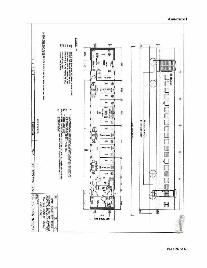
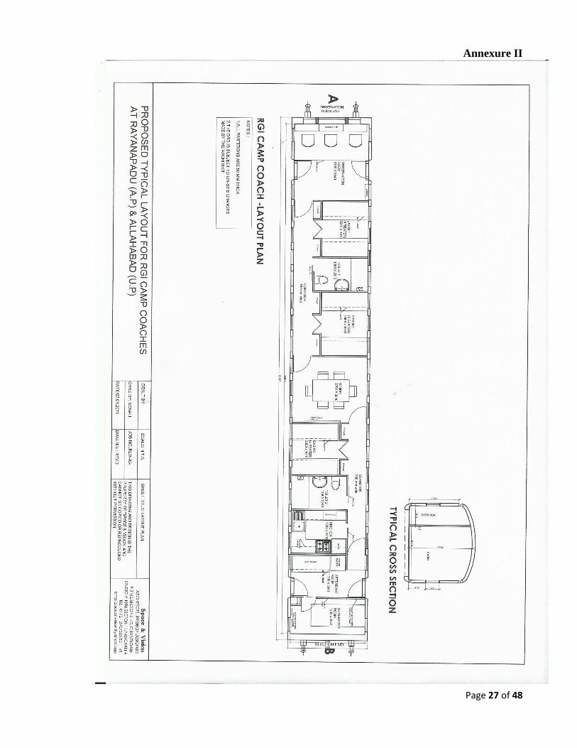
7.2. Typical layouts of coaches, with/without operational controls are given at Annexure I & II
of the Technical Specification. These layouts are for guidance of tenderers in respect of the
facilities required and general arrangement thereof.
7.3. Tenderer can propose modifications in layout as a part of technical proposal while
providing the required facilities as per typical layout. Overall dimensions of the rest van
will be within (+/-) 10% of the typical layout subjected to conformity to the Indian
Railways standard metric BG schedule of Dimensions-2004 incorporating all correction
slips up to date. The modifications proposed by tenderer will be discussed with tenderer
during technical evaluation and necessary modifications required by IR will be
incorporated by the tenderer as per mutual consent. If any further modifications are
required by the successful contractor at the stage of detailed design, the same will be
subjects to approval of RDSO.
7.4. Rest vans should be air conditioned and fully furnished for comfortable stay of operation &
maintenance crew and IR personnel.
7.5. Minimum amenities to be provided in rest vans, its color scheme and other details shall be
as per Correction Slip no.12 of IRTMM-2000.A Washing machine, Microwave oven and
communication gadgets are also to be provided.
8. BRAKES:
8.1. Machine shall be equipped with compressed air brake system applying brakes equally on
all wheels and provision shall be made to connect air brake system of the machine to that
of camping coach/wagons when the machine is hauling it. Fail safe braking mechanism
system shall be provided so that in case of any failure of brake circuit, will result in
automatic application of brake. The pneumatic parking brake should also be spring loaded
so that in case of drop in pneumatic pressure below certain value the brake will be
automatically be applied. The brakes shall be protected from ingress of water, grease, oil or
other substances, which may have an adverse effect on them. The brake lining shall be
suitable for high ambient temperature of 550
C.The force required for operating the brake
Page 16 of 48
shall not exceed 10 kg at the handle while applying by hand and 20 kg on the pedal, when
applied by foot. In addition, mechanical brakes shall also be provided for parking.
8.2. The rail grinding machine shall have provision for suitable air brake system in the driving
cabins to brake the entire consist including camping coach/crew rest van and water wagon
attached as a part of its consist/formation. Fail safe braking mechanism system shall be
provided so that in case of any failure of brake circuit will result in automatic application of
brake. The pneumatic parking brake should also be spring loaded so that in case of drop in
pneumatic pressure below certain value the brake will be automatically be applied.
8.3. The machines shall be equipped with suitable air brake valves so that while working in
train formation, machines can be braked by the traction vehicle.
8.4. There should be provision of emergency brake application in the machine either travelling
alone or coupled with the coach/wagons, in addition to the normal braking system of the
machine, using the compressed air. The emergency braking distance (EBD) of the machine
on the Indian Railway Track, at the maximum design speed on level track shall not be more
than 600 m. Design calculations for the braking effort and EBD at the maximum design
speed of the machine on level track & at falling grade of 1 in 33 should be provided by the
supplier.
8.5. Provision of “Manual operated hand brake” system shall be provided.
8.6. Clearly visible brake lights shall be provided at both the ends of the machine, which will be
automatically operated when brake is applied and switched off when brake is released. This
will be to alert the operator of machine following this machine when the machines are
working in groups.
9. HORN, HOOTER AND SAFETY MECHANISM:
9.1. The Machines shall be provided with dual tone (low tone & high tone) electric horns/ at
suitable locations facing outwards at each end of the machine for use during travelling to
warn the workmen of any impending danger. Controls/switches shall be provided in close
proximity to the driver permitting the driver to operate either horn individually or both
horns simultaneously. The horns shall be distinctly audible from a distance of at least 400
m from the machine and shall produce sound of 120-125 dB at a distance of 5 meter from
horn (source of sound). The higher tone horn shall have fundamental frequency of 370 ±15
hertz. These electric horns shall be operated by means of push buttons provided in the cabs.
9.2. The Machines shall have arrangement for flasher lights at both ends.
9.3. Pneumatically/electrically operated hooters capable of producing intensity of sound
between 105-110 dB at a distance of 5 meter (when measured in still air in a closed room)
and variation in intensity of sound shall not be more than 5 dB. The hooter shall be
provided facing outwards at each end of the machine at suitable locations, operated by
means of push buttons provided in the cabins to warn the staff working on/around the
machine about approaching train on adjoining track. Additionally switches for such hooter
shall be provided outside on the machine frame and near the both side exit gates so that it
can be operated by staff present at work site near the machine. The hooter shall also be
operatable from remote point at a distance of at least 300 m from the hooter.
Page 17 of 48
9.4. Safety equipments like jacks, pullers, tirfor and other such equipments specific to the
machines for restoring failed units of the machines during working, shall be provided on
the machines. The tenderer should submit the list of safety equipment to be provided.
9.5. Adequate numbers of safety stop/ switches should be provided all around so that in case of
any danger to worker as well as hitting of any obstructions by working unit like signalling
cable, joggle fish plate etc. during work,so that the operator can be warned or the machine
can be stopped immediately.
9.6. In addition, separate electric horns with push bottom type switches shall be provided at
suitable locations in all cabin(s) and on machine body for communication between the
machine staff about infringement/malfunctioning or any other trouble
9.7. Machines shall be provided with emergency backup system to wind up the machines in the
event of failure of prime mover or power transmission system of the machine. The
emergency backup system should able to be operated manually and may also use a manual
hydraulic power pack in addition to the emergency generator / battery based electric
hydraulic system.
9.8. The grinding carriages of rail grinding machine should have non-flammable shields and
guards so as to avoid damage due to sparks, grinding dust and flying debris.
9.9. The rail grinding machine shall have a UV and Temperature based fire detection system
that will alert the operator. There shall be an arrangement that when the fire extinguisher is
activated,if electronic control of engine detected malfunction, the engine automatically
shuts down.
9.10. There shall be arrangement on rail grinding machine to prevent dust from the grinding
process from escaping into the air. A suitable and efficient “dust collection system” shall
be provided on the machine.
10. HOOKS AND BUFFERS:
The machines shall be fitted with transition CBC couplingas per RDSO specification no.
56-BD-07 with latest revision along with side buffers to RDSO drawing no. RDSO/SK-
98145 with latest alteration on both the ends for coupling it with other vehicles for running
it in train formation and for attachment with the coach, locomotives and wagon.
11. HEAD LIGHT, FLASHER LIGHT AND OTHER LIGHTING ARRANGEMENTS:
The electrical equipment to be provided on machines shall conform to relevant standard
specifications and shall be suitable for Indian climatic conditions. The machine shall be
equipped with Twin beam headlight assembly conforming to RDSO’s specification no.
ELRS/SPEC/PR/0024 Rev-1, Sept 2004 with latest amendments ensuring a light intensity
of 3.2 lux at ground level at track centre at a distance of 305 mts. away on a clear dark
night, at each end and with two front and rear parking lights, which can be switched to red
or white according to the direction of the travel. Powerful pressurize floodlights shall also
be provided to illuminate the working area sufficiently bright for efficient working during
night. In addition minimum eight power point locations shall be provided on outside frame
of the machine two in front, two in rear and two on both sides for providing lighting
Page 18 of 48
arrangements during night working. The umber colour LED based flasher lights producing
not less than 500 lux at 1 meter and 55 lux at 3 meter in line measurement in axial direction
from flasher light shall be provided at both ends on the machine to give indication for the
train arriving on the other line.
12. CHASSIS AND UNDERFRAME:
The chassis of machines shall be fabricated from standard welded steel section and of steel
sheets, so as to permit transportation of the machine in train formation without endangering
safety of the train. The under frame shall be constructed with rolled steel section and/or
plates and shall be designed to withstand a maximum static squeeze test load of 102t at
buffers i.e. 51t at each buffing point without any permanent distortion. The under frame
shall be sufficiently robust for safe travel of the machine in train formation.
13. CABINS:
13.1. The machines shall be equipped with fully enclosed air conditioned and pressurized cabins
with safety glass window at both the ends. It shall be possible to have a clear view of the
track ahead while driving the machine in both the directions from the cabins at either end.
The cabin layout shall be such that, before leaving the machine, the operating staff has full
view on both the sides, to avoid any danger to them from trains on the adjacent tracks.
13.2. The gauges, instruments and controls panel shall be suitably located in the operator’s cab
so that they can be observed without undue fatigue to the operator.
13.3. The operator’s cabin shall be ergonomically designed to have easy access to all controls.
13.4. Screen wipers preferably operated by compressed air or electricity shall be provided on the
windscreens
13.5. Suitable number of fire extinguisher shall be provided in all the vehicles. The chemicals
used for extinguishing fire by such fire extinguishers shall not chemically react with
electronic equipments/components, PCBs, cables etc.
13.6. The machines shall be provided with well-defined space for keeping the tools and spares
required for at least one week of operation and onsite repair of the machine to attend the
breakdowns and other working requirements.
13.7. Large window shall be provided in both cabs of the rail grinding machine at low level to
ensure good visibility for the operator controlling working and driving of machines to
observe the track features and to operate the controls based on the features/obstructions
being approached and cleared Facility of driving the machine for travelling purpose shall
be from both the cabins. All travelling and grinding control shall be housed in the air-
conditioned cabins.
13.8. Inter-communication system wired/wireless shall be provided inter-connecting all the
cabins and coaches and outside of machine should be so oriented that the operator, seating
on the seat of either cabins/working cabin, can distinctly hear the conversation and
communicate with other staff.
Page 19 of 48
13.9. The machine shall be equipped with speed indicator and recording equipment of range
between 0 - 120km/h for recording the speed of the machine in real time basis. The
recorded data should be retrievable on computer through memory card/pen drive. It should
be provided in the driving cabin at suitable place and recording system should have
sufficient memory to keep the speed record of minimum 15 days which should always be
stored for retrieving as per requirement
14. TOOLS AND INSTRUCTION MANUALS:
14.1. Each machine shall be supplied with a complete kit of tools required by the operator in
emergency and for normal working of the machines. The list of tools to be provided shall
also include all tools necessary for maintenance and repair of the entire machine including
specialized equipment, like hydraulic jacks, welding equipment, wheel truing shoes,
refractometer, power tools, air hoses/wands, etc. all special tools shall be listed and
catalogued illustrating the method of application.The list can be modified to suit the
purchaser's requirement, while examining the offer. The supplier shall include all items,
tools and accessories required for proper operation, servicing, maintenance, assembly
overhauling, periodical overhauling of the machine along with the offer and not mentioned
in these specifications and supply the same along with the machine.
14.2. Detailed operating manual, maintenance and service manual shall be specifically prepared
in English Language and four copies of these shall be supplied with each machine.
14.3. The manufacturer shall also supply circuit diagrams of electrical hydraulic, pneumatic and
electronic circuits used on the machine. Trouble shooting diagram/table shall also be
supplied. In addition, the supplier shall provide dimension drawings with material
description of items like rubber seals, washers, springs, bushes, metallic pins etc., main
features such as type, RPM & discharge etc. of items like hydraulic pump-motors, and the
tenderer shall furnish the details of such other bought out components/assemblies. These
shall be specially prepared in English language and four copies of these shall be supplied
with each machine.
14.4. Complete technical literature in english to be supplied with the machines should be sent 3
months in advance of inspection of the first machine to RDSO for their review regarding
adequacy and manner of detailing. Necessary modifications and further detailing as per
RDSO’s comments should be carried out and compliance should be reported to RDSO as
well as the Inspecting officer of the first machine.
14.5. The firm shall provide detailed technical drawings and specifications of wheels and axles
used on the machines. The above details shall be provided in four sets with each machine.
14.6. One set each of all the manuals and diagrams should be sent to the Principal/IRTMTC,
Allahabad, ED/TM/RDSO, Lucknow, DTK(MC)/ Railway Board and
Director/IRICEN/Pune along with supply of first machine. In case there is any subsequent
amendment in above documents based on field performance, the amendment/amended
documents should also be sent to above mentioned authorities.
14.7. Each machine should be supplied with following Equipments-
Page 20 of 48
a. Two contact based rail profile measuring equipment shall be supplied by
manufacturer along with machine as per RDSO Specification no. TM/SM – 323
b. Bar gauge with appropriate templates
c. Digital inclinometer
d. Rail Hardness measuring equipment
e. Rail Roughness measuring equipment
15. SPARE PARTS:
15.1. The expected life of the components shall be advised along with their condemning limits.
15.2. The manufacturer shall be responsible for the subsequent availability of spare parts and
grinding stones to ensure trouble free service for the life of the machine. (Minimum 15
years)
15.3. For indigenous parts and bought components and assemblies, the source (original
equipment manufacturer’s reference and part no.) and other relevant technical details shall
be supplied while offering the first machine for inspection.
16. MAKER’S TEST CERTIFICATE:
16.1. Copies of maker’s certificate guaranteeing the performance of the machine shall be
supplied in duplicate along with the delivery of each machine.
17. OPERATORS:
17.1 The number of operators and allied staff for working of the machines under normal
condition shall be indicated, specifying their duties and minimum qualifications.
18. OPTIONAL EQUIPMENT:
18.1 Tenderer is expected to quote for optional equipment separately for each item giving the
advantages/functions of such optional equipment. Tenderer shall also indicate whether
such equipment is already in use on machines elsewhere indicating the user Railway
system.
19. INSPECTION:
19.1. While inspecting the machine before dispatch from the supplier’s premises, the inspecting
officer to be nominated by the purchaser shall verify the conformity of the machine with
respect to individual clause of technical requirements laid down in this specification. The
machine’s conformity/non-conformity with respect to each item shall be jointly recorded,
before the issue of the “Inspection certificate and approval for dispatch of the machine” as
per Annexure-VI enclosed.
19.2. Following arrangements shall be made by the supplier/Manufacturer at the inspection
premises for carrying out inspection of the machine by inspecting officials:
i. Machine to be stabled on straight & level BG track. The length of the track should be
at least 10 m more than buffer to buffer length of machine.
Page 21 of 48
ii. In order to check Maximum Moving dimensions in cross section, a sturdy frame of IR
Max Moving Dimensions shall be provided by the manufacturer and passed over the
machine holding it perpendicular to track, centre aligned with track centre.
Adequate arrangements shall be made to the satisfaction of inspecting official.
19.3. The following documents shall be provided to the Inspecting Officer at least 30 days in
advance of the date of inspection.
i. One copy of complete technical literature mentioned in clause 14, in English language,
including operation, service and field maintenance manuals/instructions and complete
electrical, hydraulic and pneumatic circuit diagrams, trouble shooting charts,
component drawings/ description and other relevant technical details as a reference
documents for the inspecting officer.
ii. Cross section of the machine super imposed on IR maximum moving dimensions
envelope shall be provided to IO in advance.
iii. Clause by clause comments of the manufacturer to be sent to Inspecting Officer (IO) in
advance for his review. Comments should state manufacturer’s conformity of
compliance of each of the requirement stated in each clause, elaborating where
necessary the details/manner in which the requirement has been complied. The
proforma of draft inspection report for the clause-wise comments is given below:
Clause No. Clause Comments of
Supplier/manufacturer
Comments of Inspecting
Officer
(To be filled by inspecting
officer)
iv. Manufacturer’s Internal Quality Inspection Report of the machine.
v. Manufacturer’s quality certificate and/or test reports for bought out assemblies/ sub-
assemblies to be provided to IO, containing serial number wherever applicable.
vi. Draft Inspection Report to be prepared by the manufacturer, containing all annexure
mentioned at para 19.4.
vii. Details of arrangements made for checking Maximum Moving Dimensions for his
approval.
Supplier will incorporate amendments/further clarification in the above documents to the
satisfaction of the Inspecting Officer keeping in view the Inspecting Officer’s comments, if
any.
19.4. List of documents to be annexed in the draft Inspection Report should include:
Page 22 of 48
i. Maker’s Test Certificate.
ii. Manufacturer’s Internal Quality Inspection Report
iii. Quality Certificates of Bought out assemblies/ sub-assemblies
iv. Cross section of the machine super imposed on the IR MMD
v. Vogel’s diagram
vi. List of spare parts to be dispatched along with the machine
vii. List of tools to be dispatched along with the machine
viii. List of. Manuals, Drawings, Spare Parts Catalogues, etc. to be dispatched along
with the machine, duly indicating the number of sets of each.
Above documents shall be part of final inspection report
20. Issue of Provisional Speed certificate
Whenever a new rolling stock is introduced in Indian Railways, a provisional speed
certificate is issued by RDSO, based on certain design parameters of the vehicle. Final
speed clearance of the vehicle is given after conducting detailed oscillation trial of the
vehicle, which is a time taking process. Therefore, issue of provisional speed certificate for
the vehicle becomes a necessity and based on the same, the approval of running of the
vehicle on Indian Railway track is taken from Commissioner of Railway Safety. For issue
of provisional speed certificate, the following actions are required to be taken by the
suppliers.
A- Current suppliers, whose models are approved:
The supplier shall give details of the model, year of introduction in Indian Railway, details
of speed certificate issued etc. The supplier shall certify that no change has taken place in
the model being offered with respect to design of under carriage i.e. suspension system
/arrangement, wheel & axle assembly, bogie, braking arrangement loading pattern of the
vehicle etc. and the distribution of axle loads, lateral forces, unsprung mass and braking
force coming on rail is the same. If, there is any change in above respect, the action shall be
taken as detailed in para (B) below:
B- Current suppliers, whose models are not approved / or new:
As soon as the supplier completes the design of the machine as per specifications, the
technical details as per Annexure (VIII/A,B&C) shall be supplied for processing of
provisional speed certificate for the machine so that it can be permitted to move on track.
On case-to-case basis, more technical details (other than mentioned in Annexure VIII/A, B
& C) can also be asked for issue of provisional speed certificate for the machine.
C- New suppliers, whose models are new:
The technical details shall be supplied as detailed in para (B) above.
21. MARKING & COLOUR:
21.1. The machine body shall be painted in golden yellow colour, conforming to RDSO
specification No M & C/PCN/109/88 (with latest amendment) to minimum DFT of 80 mm.
Colour code to be ISC: 356.
21.2. Following should be written on the machine at appropriate location (as per Annexure IX)
(i) Indian Railway’s logo of height between 300 mm to 600 mm as suitable on all four
faces of the machine.
Page 23 of 48
(ii) On both side faces, below the Indian Railways logo, the text “ INDIAN
RAILWAYS” to be written in Bold and in Black colour of size equal to or slightly
smaller than the size of logo but of size not less than 250 mm.
(iii) Below the text “INDIAN RAILWAYS” mentioned above, Machine model and
manufacturing Year should be written in black color and in letter of size less than
the size in which Indian Railways is written but not less than 200 mm in any case.
(iv) If desired by the Manufacturers, his Name may be written in size not more than 150
mm and should not be at more than four locations. Also the Manufacturers Logo
may be provided at not more than two Locations and should be of size less than
200mm.
22. Acceptance test-The acceptance test as below shall be carried out at the time of
commissioning of machines in India at the consignee Railway.
22.1. Rail Grinding Machine : The acceptance test of Rail Grinding Machine shall consist of:
A. Dimensional test of the loading gauge, maximum moving dimensions, buffer heights,
clearances etc.
B. Testing for negotiability of 10-degree curve and 1 in 8.5 turnouts.
C. Train running speed tests (light running) on the Indian Railway main line track in
accordance with the procedure outlined at Annexure –VII.
D. Construction and engineering of the machine.
E. Output performance quality tests with High carbon 90 UTS/110 UTS H.H. rails with
60-kg/52 kg UIC section.
F. Profile of the rail section shall not be deformed.
G. For the purpose of metal removal capability of the machine (clause 3.16), 5 sites of
minimum 500m each shall be selected. At each site measurement of both left and right
rail shall be taken.
i. At each site, the machine shall grind a length of at least 500 meters to ensure that the
stones are not heated up.
ii. The profile of the rail shall be close to the desired profile.
iii. The rail hardness shall be measured and recorded.
iv. A each site, on the test rails, 5 X-sections shall be selected on both rails. These X-
sections shall be at least 2 meters away from any weld/fish plated joint and not in
heavily corrugated rail.
v. The X-sectional area shall be recorded, at each X-section, before the grinding, and
after 1 grinding pass. The working speed, while grinding shall be maintained as
specified.
vi. The average material removal per pass for the site shall be the average of material
removal per pass at 5 X-sections.
vii. The average material removal per pass at the specified speed at each of the 5 sites both
left and right rail separately shall be more than that specified in clause 3.15.
H. For the purpose of depth of metal removal capability of the machine (clause 3.16), 5
sites of minimum 500m each shall be selected for carrying out tests at the speeds
mentioned in clause 3.16. At each site, measurement of both left and right rail shall be
taken:
i. At each site, the machine shall grind a length of at least 500 meters to ensure that the
stones are not heated up.
ii. The profile of the rail shall be close to the desired profile.
iii. The rail hardness shall be measured and recorded.
Page 24 of 48
iv. 5 points shall be chosen at 5 locations across the X-section, one towards gauge face
side, three in the middle of rail top and one towards non-gauge face side such as to
cover full width of rail head, at 5 X-sections on both rails at each of the 5 sites.
v. The working speed, while grinding shall be maintained as specified. The depth of
metal removed shall be measured by measuring the depth of cut before and after 1
grinding pass (as per para no. 21.1/G/v). Measurement to be done with Contact based
Rail profile measurement Device with or better precision/accuracy.
vi. The average of the 25 observations at each site for each rail shall be worked out. The
average depth of metal removal per pass for the site shall be the average depth of
material removed for all 25 test points.
vii. None of the average depth of metal removal per pass for a site, out of 5 selected sites
for both rails should be less than as specified at clause 3.16 for the respective grinding
speed.
I. Stoppages of work not attributable to machine shall be discounted.
J. The difference in the target profile and ground profile ie profile achieved after
grinding, shall not more than + 1% in terms of cross sectional area of rail head.
K. The machine will also be operated at suitable locations in working mode for
continuous 5 hours to ensure the machine’s continuous working capability for this type
of work and test the life of the grinding stones as specified at clause 3.20.
22.2. Should any modifications be found necessary as a result of the tests, these shall be carried
out by the supplier at his own expense.
23. TRAINING:
23.1. The supplier shall impart professional training to IR Personnel in various aspects of
operation, maintenance and management of the machine, planning and designing rail
grinding program, inspection, monitoring, quality control and review as per the brief scope
defined in Annexure-IV.
The tenderer will submit detailed program covering scope and coverage in detail, place and
manner in which the training will be imparted so that a satisfactory level of knowledge and
skill is developed by IR Personnel for satisfactory implementation of grinding program
23.2. E-Learning courses module should be arranged for imparting training to railway operators.
In addition, the service engineer shall provide hands on training to railway staff in
calibration operation, repairing and maintenance of the machine in field to make them fully
conversant with the machine. The engineers shall also advise the Railways on appropriate
maintenance, testing, operating, repair and staff training facilities that are necessary for the
efficient performance of the machines.
24. WARRANTEE AND POST WARRANTY MAINTENANCE CONTRACT
The machine shall be warranted for 24 months from date of commissioning at ultimate
destination in India Design modification made in any part of the machine offered, the
warranty period of 24 months would commence from the date of modification and proving

Page 25 of 48
test of machine for the purpose of that part and those parts which may get damaged due to
defects in the new replaced part. The cost of such modification should be borne by the
supplier.
Other warrantee and post warranty clause wise term and conditions are attached as
Annexure –XI.
Page 26 of 48
Annexure I
Page 27 of 48
Annexure II
Page 28 of 48
Annexure III
Page 29 of 48
Annexure- IV
Scope of Training to be imparted by Manufacturer/Supplier to IR Personnel
The training program shall consist of the following modules-
1. For Senior Engineering officers of IR-
Four senior IR personnel shall be given training for a period of two weeks in
manufacturing plant of manufacturer/supplier and/or affiliated institute/training centers
and field operation where the machines are already in operation. Broad scope of this
training shall be to provide quality training in the areas of management of grinding,
machine familiarization, machine utilization, managerial aspects of operation and
maintenance of the machine, grinding strategy, best practices for optimal performance,
reporting, quality control, producing quality rail profiles, progressive review of grinding
strategy program, important safety aspects, vendor support.
2. For Track Machine organization Personnel –
This training will cover operation and maintenance of the machine. The broad scope of
this training will be as under:
Machine’s general arrangement including air systems, mechanical systems,
hydraulic systems, electrical systems, rail measurement systems, controls etc.
Operation of the machine in working mode (grinding) and travel mode.
Maintenance and overhauling of rail grinding machine.
Recording of rail profiles, use of Rail Inspection data and preparing the grinding
program.
Trouble shooting skills.
Responses of emergency situations
Basics of producing quality rail profiles.
The training will be conducted as per following sub-modules-
2.1. 12 IR personnel shall be given training for a period of Three weeks at contractors
manufacturing premises about machine assembly line in different shops, operation,
repair and maintenance. Also they will be given on-site training in field operation
abroad where same type of machine is already in operation for the contract.
2.2. In India, training of 12 IR personnel per machine for four weeks will be given in
operation and maintenance of the machine. Out of four weeks, at least two weeks
training will be imparted at the site of commissioning of the machines and has to be
completed before commissioning of machines. The remaining period of training will be
imparted in one or two modules spread over warranty period in the form of
refresher/updating training at the time of delivery of each machine. Details of the
proposed program should be given in the offer.
3. For P-Way Personnels –
Page 30 of 48
This training will cover design, planning, quality control, monitoring and review of
grinding program. The broad scope of this training will be as under:
Technical aspects of Rail Grinding and the benefits
Rail grinding functions and best practices for optimal performance.
Basics of producing quality rail and wheel profiles.
Rail and wheel interaction.
Technical aspects of rail lubrication, and planning the lubrication strategies.
Understanding and development of rail grinding program based on RCF,
surface defects and profile deterioration.
Monitoring of rail grinding result, its benefits and review of the grinding
program.
Rail Grinding Implementation and quality control.
Track inspection and data collection for rail grinding
Designing of optimal rail- wheel profiles
Establishment of test sites and monitoring
Designing rail grinding strategies and program
The training will be conducted as per following sub-modules-
3.1. 12 IR personnel shall be given three weeks training at manufacturer’s premises and/or
affiliated institute/training centre, this training shall include taking rail profile, wheel
profile, work on simulation software for different contact location of rail-wheel
interface, designing theory for developing required rail profiles, different pattern for
achieving the required rail profile and calculate rail life and such other aspects in the
contract.
3.2. In India training for 12 IR personnel per machine for six weeks will be given at site of
grinding / railway premises. This training includes taking rail profile pre-post grind
and use of other handheld gadgets for inspection of grounded rail and contact bend
before and after, how to maintain data base for grind quality, for establishing efficient
Rail Grinding Management system on Indian Railways for each machine. This module
of training may be staggered in suitable phases prior to supply of machines, post
supply and mid warranty review/refresher.
4. Tenderers are required to submit detailed proposal of the training program along with
their offer. The topics, detailed content of training, demonstrations, site visits and
hands-on experience should be elaborated in detail in the offer. The names of
manufacturing premises, affiliated institute/training centre where abroad training is
proposed to be conducted should be detailed in the training proposal in the offer.
Further details of places where field visits, demonstrations, hands on experience etc are
proposed to be conducted may be submitted within 90 days of signing the contract
agreement.
5. All the cost for arranging and facilitating the training are to be borne by the supplier.
Tenderers are required to quote the prices for training as per tender conditions.
However training as per 2.2 and 3.2 will be at suppliers cost and nothing extra shall be
paid for the same. The cost of boarding, lodging and air fare of IR personnel shall be
borne by the purchaser and should not be included in tenderer’s quote.
Page 31 of 48
Annexure- V
Page 32 of 48
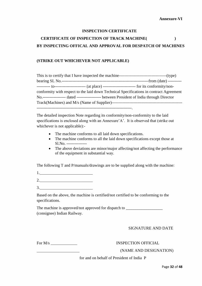
Annexure-VI
INSPECTION CERTIFICATE
CERTIFICATE OF INSPECTION OF TRACK MACHINE( )
BY INSPECTING OFFICAL AND APPROVAL FOR DESPATCH OF MACHINES
(STRIKE OUT WHICHEVER NOT APPLICABLE)
This is to certify that I have inspected the machine-----------------------------------(type)
bearing SL No.----------------------------------------------------------------from (date) ----------
---------- to----------------------- (at place) ------------------------ for its conformity/non-
conformity with respect to the laid down Technical Specifications in contract Agreement
No.----------------- dated ------------------ between President of India through Director
Track(Machines) and M/s (Name of Supplier)----------------------------------------------------
----------------------------------------------------------------------.
The detailed inspection Note regarding its conformity/non-conformity to the laid
specifications is enclosed along with an Annexure’A’. It is observed that (strike out
whichever is not applicable):-
The machine conforms to all laid down specifications.
The machine conforms to all the laid down specifications except those at
Sl.No. ---------------
The above deviations are minor/major affecting/not affecting the performance
of the equipment in substantial way.
The following T and P/manuals/drawings are to be supplied along with the machine:
1.__________________________
2.__________________________
3.__________________________
Based on the above, the machine is certified/not certified to be conforming to the
specifications.
The machine is approved/not approved for dispatch to __________________
(consignee) Indian Railway.
SIGNATURE AND DATE
For M/s _____________ INSPECTION OFFICIAL
_____________________ (NAME AND DESIGNATION)
for and on behalf of President of India P
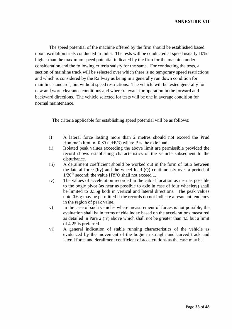
Page 33 of 48
ANNEXURE-VII
The speed potential of the machine offered by the firm should be established based
upon oscillation trials conducted in India. The tests will be conducted at speed usually 10%
higher than the maximum speed potential indicated by the firm for the machine under
consideration and the following criteria satisfy for the same. For conducting the tests, a
section of mainline track will be selected over which there is no temporary speed restrictions
and which is considered by the Railway as being in a generally run down condition for
mainline standards, but without speed restrictions. The vehicle will be tested generally for
new and worn clearance conditions and where relevant for operation in the forward and
backward directions. The vehicle selected for tests will be one in average condition for
normal maintenance.
The criteria applicable for establishing speed potential will be as follows:
i) A lateral force lasting more than 2 metres should not exceed the Prud
Homme’s limit of 0.85 (1+P/3) where P is the axle load.
ii) Isolated peak values exceeding the above limit are permissible provided the
record shows establishing characteristics of the vehicle subsequent to the
disturbance.
iii) A derailment coefficient should be worked out in the form of ratio between
the lateral force (hy) and the wheel load (Q) continuously over a period of
1/20th
second; the value HY/Q shall not exceed 1.
iv) The values of acceleration recorded in the cab at location as near as possible
to the bogie pivot (as near as possible to axle in case of four wheelers) shall
be limited to 0.55g both in vertical and lateral directions. The peak values
upto 0.6 g may be permitted if the records do not indicate a resonant tendency
in the region of peak value.
v) In the case of such vehicles where measurement of forces is not possible, the
evaluation shall be in terms of ride index based on the accelerations measured
as detailed in Para 2 (iv) above which shall not be greater than 4.5 but a limit
of 4.25 is preferred.
vi) A general indication of stable running characteristics of the vehicle as
evidenced by the movement of the bogie in straight and curved track and
lateral force and derailment coefficient of accelerations as the case may be.
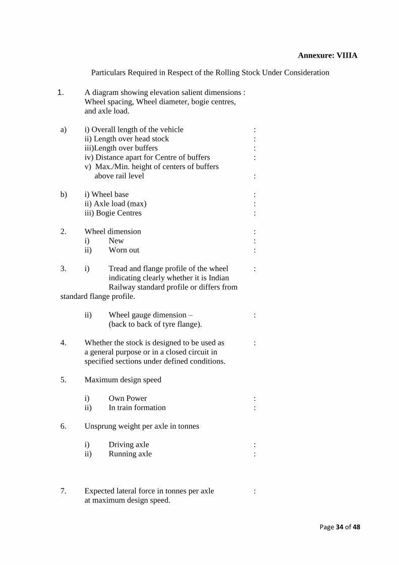
Page 34 of 48
Annexure: VIIIA
Particulars Required in Respect of the Rolling Stock Under Consideration
1. A diagram showing elevation salient dimensions :
Wheel spacing, Wheel diameter, bogie centres,
and axle load.
a) i) Overall length of the vehicle :
ii) Length over head stock :
iii)Length over buffers :
iv) Distance apart for Centre of buffers :
v) Max./Min. height of centers of buffers
above rail level :
b) i) Wheel base :
ii) Axle load (max) :
iii) Bogie Centres :
2. Wheel dimension :
i) New :
ii) Worn out :
3. i) Tread and flange profile of the wheel :
indicating clearly whether it is Indian
Railway standard profile or differs from
standard flange profile.
ii) Wheel gauge dimension – :
(back to back of tyre flange).
4. Whether the stock is designed to be used as :
a general purpose or in a closed circuit in
specified sections under defined conditions.
5. Maximum design speed
i) Own Power :
ii) In train formation :
6. Unsprung weight per axle in tonnes
i) Driving axle :
ii) Running axle :
7. Expected lateral force in tonnes per axle :
at maximum design speed.
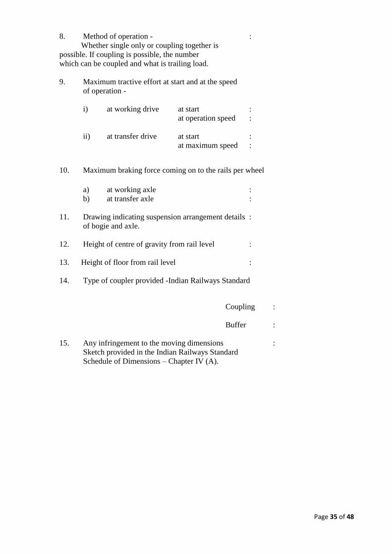
Page 35 of 48
8. Method of operation - :
Whether single only or coupling together is
possible. If coupling is possible, the number
which can be coupled and what is trailing load.
9. Maximum tractive effort at start and at the speed
of operation -
i) at working drive at start :
at operation speed :
ii) at transfer drive at start :
at maximum speed :
10. Maximum braking force coming on to the rails per wheel
a) at working axle :
b) at transfer axle :
11. Drawing indicating suspension arrangement details :
of bogie and axle.
12. Height of centre of gravity from rail level :
13. Height of floor from rail level :
14. Type of coupler provided -Indian Railways Standard
Coupling :
Buffer :
15. Any infringement to the moving dimensions :
Sketch provided in the Indian Railways Standard
Schedule of Dimensions – Chapter IV (A).
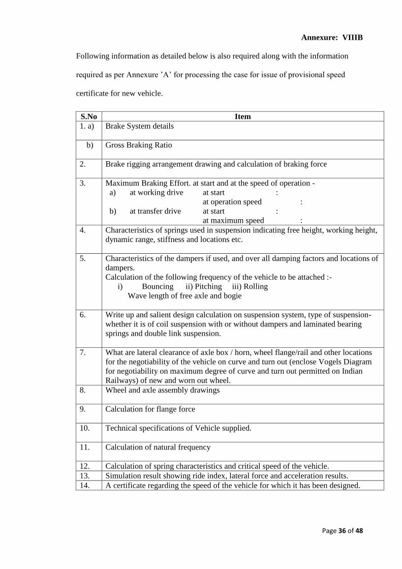
Page 36 of 48
Annexure: VIIIB
Following information as detailed below is also required along with the information
required as per Annexure ’A’ for processing the case for issue of provisional speed
certificate for new vehicle.
S.No Item
1. a) Brake System details
b) Gross Braking Ratio
2. Brake rigging arrangement drawing and calculation of braking force
3. Maximum Braking Effort. at start and at the speed of operation -
a) at working drive at start :
at operation speed :
b) at transfer drive at start :
at maximum speed :
4. Characteristics of springs used in suspension indicating free height, working height,
dynamic range, stiffness and locations etc.
5. Characteristics of the dampers if used, and over all damping factors and locations of
dampers.
Calculation of the following frequency of the vehicle to be attached :-
i) Bouncing ii) Pitching iii) Rolling
Wave length of free axle and bogie
6. Write up and salient design calculation on suspension system, type of suspension-
whether it is of coil suspension with or without dampers and laminated bearing
springs and double link suspension.
7. What are lateral clearance of axle box / horn, wheel flange/rail and other locations
for the negotiability of the vehicle on curve and turn out (enclose Vogels Diagram
for negotiability on maximum degree of curve and turn out permitted on Indian
Railways) of new and worn out wheel.
8. Wheel and axle assembly drawings
9. Calculation for flange force
10. Technical specifications of Vehicle supplied.
11. Calculation of natural frequency
12. Calculation of spring characteristics and critical speed of the vehicle.
13. Simulation result showing ride index, lateral force and acceleration results.
14. A certificate regarding the speed of the vehicle for which it has been designed.
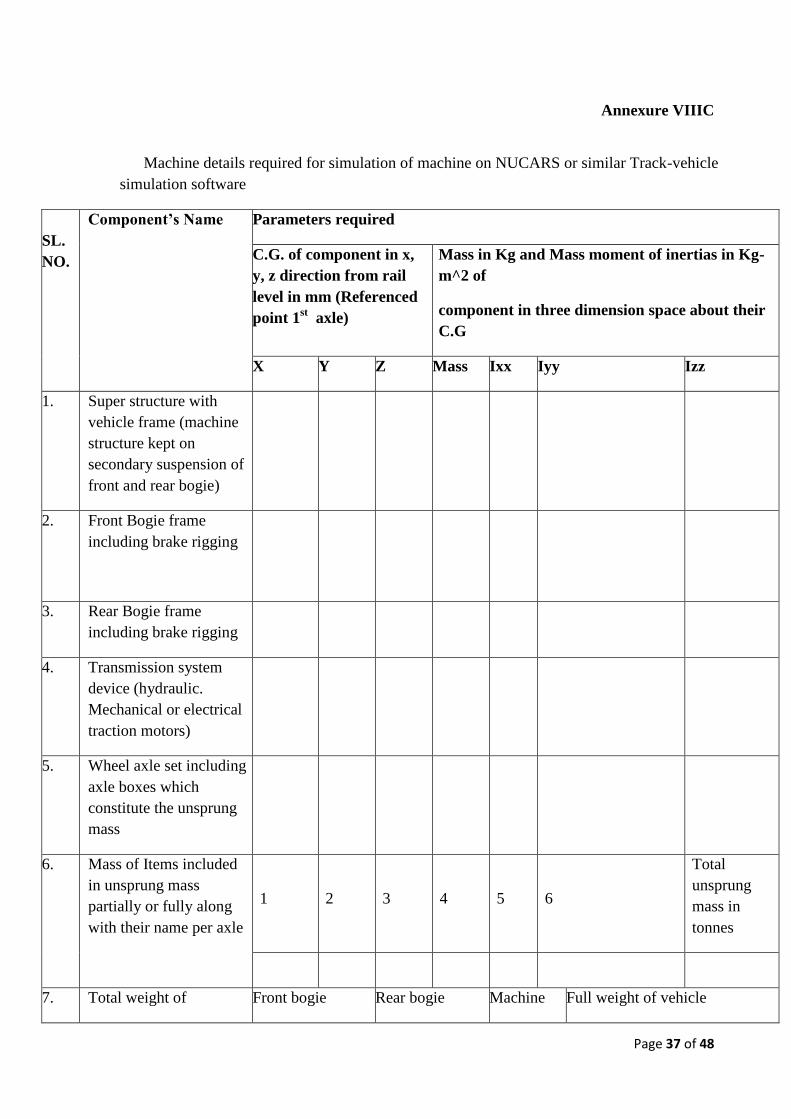
Page 37 of 48
Annexure VIIIC
Machine details required for simulation of machine on NUCARS or similar Track-vehicle
simulation software
SL.
NO.
Component’s Name Parameters required
C.G. of component in x,
y, z direction from rail
level in mm (Referenced
point 1st axle)
Mass in Kg and Mass moment of inertias in Kg-
m^2 of
component in three dimension space about their
C.G
X Y Z Mass Ixx Iyy Izz
1. Super structure with
vehicle frame (machine
structure kept on
secondary suspension of
front and rear bogie)
2. Front Bogie frame
including brake rigging
3. Rear Bogie frame
including brake rigging
4. Transmission system
device (hydraulic.
Mechanical or electrical
traction motors)
5. Wheel axle set including
axle boxes which
constitute the unsprung
mass
6. Mass of Items included
in unsprung mass
partially or fully along
with their name per axle
1
2
3
4
5
6
Total
unsprung
mass in
tonnes
7. Total weight of Front bogie Rear bogie Machine Full weight of vehicle
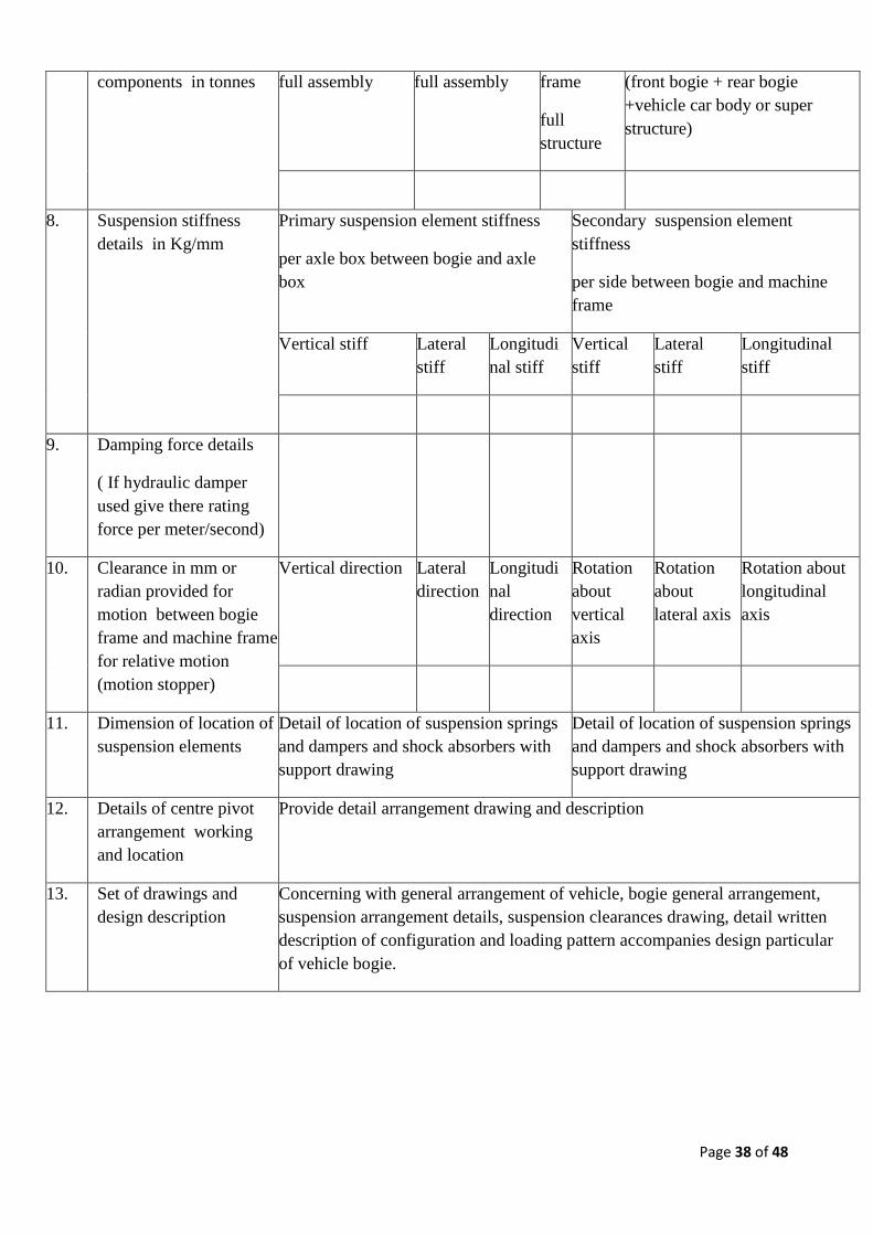
Page 38 of 48
components in tonnes full assembly full assembly frame
full
structure
(front bogie + rear bogie
+vehicle car body or super
structure)
8. Suspension stiffness
details in Kg/mm
Primary suspension element stiffness
per axle box between bogie and axle
box
Secondary suspension element
stiffness
per side between bogie and machine
frame
Vertical stiff Lateral
stiff
Longitudi
nal stiff
Vertical
stiff
Lateral
stiff
Longitudinal
stiff
9. Damping force details
( If hydraulic damper
used give there rating
force per meter/second)
10. Clearance in mm or
radian provided for
motion between bogie
frame and machine frame
for relative motion
(motion stopper)
Vertical direction Lateral
direction
Longitudi
nal
direction
Rotation
about
vertical
axis
Rotation
about
lateral axis
Rotation about
longitudinal
axis
11. Dimension of location of
suspension elements
Detail of location of suspension springs
and dampers and shock absorbers with
support drawing
Detail of location of suspension springs
and dampers and shock absorbers with
support drawing
12. Details of centre pivot
arrangement working
and location
Provide detail arrangement drawing and description
13. Set of drawings and
design description
Concerning with general arrangement of vehicle, bogie general arrangement,
suspension arrangement details, suspension clearances drawing, detail written
description of configuration and loading pattern accompanies design particular
of vehicle bogie.
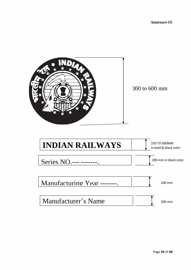
Page 39 of 48
Annexure-IX
200 mm
300 to 600 mm
INDIAN RAILWAYS 250 TO 600MM in bold & black color
Series NO.--- -------. 200 mm in black color
Manufacturer’s Name
Manufacturing Year -------.
200 mm
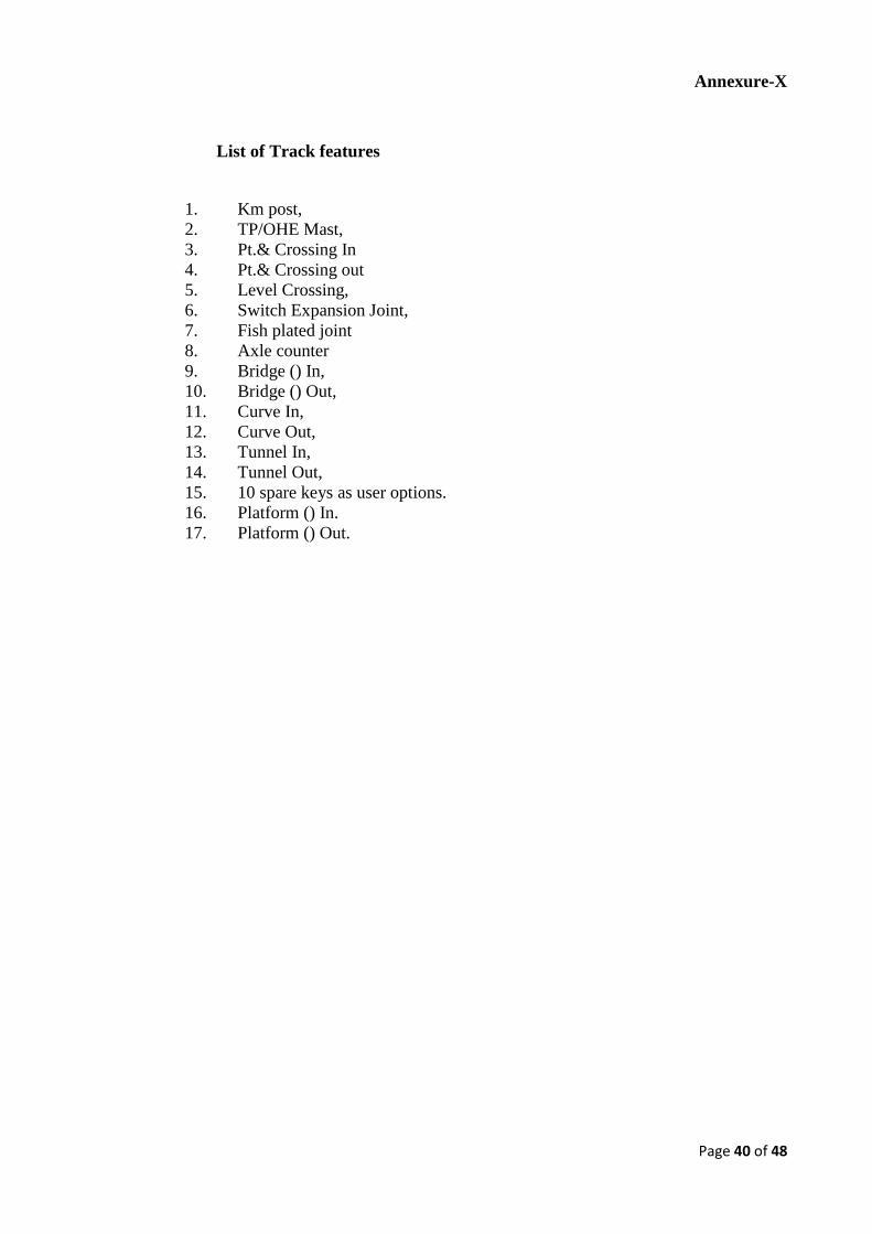
Page 40 of 48
Annexure-X
List of Track features
1. Km post,
2. TP/OHE Mast,
3. Pt.& Crossing In
4. Pt.& Crossing out
5. Level Crossing,
6. Switch Expansion Joint,
7. Fish plated joint
8. Axle counter
9. Bridge () In,
10. Bridge () Out,
11. Curve In,
12. Curve Out,
13. Tunnel In,
14. Tunnel Out,
15. 10 spare keys as user options.
16. Platform () In.
17. Platform () Out.
Page 41 of 48
Annexure-XI
1. OPERATION AND MAINTENANCE CONTRACT (DURING WARRANTY
PERIOD)
The following clauses outline the key requirements of the O&M conditions for Indian
Railways to be met by the supplier for a period of 24 months post commissioning:
1.1 The supplier or their designated Indian agent/Indian counterpart has to execute
works of Operation & maintenance of 72 stones Rail Grinding Machine which will
be deployed over many Zonal Railways as per the instructions of Consignee Zonal
Railways office. During the execution of the contract fuel, oil, water and lubricants
are to be provided by Zonal Railways free of cost to the supplier.
1.2 To operate & maintain complete the 72 stone Rail Grinding machine fully utilizing
it’s potential. The tenderer is responsible for ensuring the availability of machine for
08 hour every day for grinding operation (which might be increased by up to 2 to 3
hours depending on traffic condition over IR during operation). During maintenance
shift, the stipulated maintenance of RGM, stipulated preventive checks and schedule
maintenance of RGM machine including all assemblies (like engines, generators,
electrical control system etc.) or sub-assemblies (various water & HSD oil pumps
,sensors etc) as specified by OEM/supplier updated time to time to ensure it’s
upkeep shall be carried out.
1.3 The supplier or their designated Indian agent/Indian counterpart, has to provide
sufficient number of skilled/semi-skilled staff required (Minimum 12 staff including
6 Supervisors at a time) for operation and maintenance of RGM. Grinding operator
shall be certified by the OEM and with valid competency certificate in train
operation issued by ZRTI/IR and medically fit in A-1 Category. In case
initial/refresher course to be done for G & SR from ZRTI/IR during the currency of
this contract, the same shall be got done for the operators by the contractor and it
shall payable as applicable. Zonal Railways shall facilitate in expediting the process.
All the operators shall have valid PME certificate issued by IR and all the cost for
medical examination connected with PME, shall be payable by the contractor.
1.4 One 4 wheeler vehicle in good condition with proper road permit and
insurance(Safari/ Scorpio or similar) for transporting men and material required for
day to day working will be provided by tenderer during O&M period for use by O
& M crew and IR crew (on RGM) without any extra payment.
1.5 The RGM will work on IR track with the trains running on adjacent tracks. The
contractor must ensure the care /safety/health hazards of the labours engaged by
him/her during the course of the execution of work. Necessary safety equipment
shall be provided by the contractor for the staff engaged by the tenderer and also for
2-4 IR official nominated on this machine. No extra amount is payable toward this.
1.6 Railway shall provide adequate and appropriate security at their disposal to protect
and preserve the RGM Machine from anti-social elements especially in insurgency
defined areas, where the machine maybe required to operate from time to time.
1.7 The contractor's staff & labour shall not have any claims of appointment in
Railways in future.
1.8 Authorized Railway's representative having route learning of the particular section
where the RGM is working will be present for supervising the grinding work and to
Page 42 of 48
monitor the movement of the RGM from one section to another. RGM shall not be
moved without authorized Railway's representative. The same would be provided
free of charge.
1.9 All tools and plants, drawings, manuals which are supplied by the manufacturer to
the Railways will be handed over to the contractor free of cost for use along with
the machine. All these to be handed over back in good condition after expiry of the
contract period to authorized Railways.
1.10 RGM shall be made available for grinding operation for minimum period of 25 days
in a month and 75 days in consecutive 3 months. The balance 15 days are meant for
maintenance functions during which time all maintenance activities are to be
completed by the tenderer. While the RGM is on transit from one station to another
or waiting for loco for hauling, it will be considered as availability unless the RGM
is under breakdown preceding to this.
1.11 The supplier will be responsible for ensuring the availability of machine for eight
hours every day for at least 25 days a month and the availability certificate will be
rendered (as per enclosed Annexure - A). During these 8 hours (which may be in
two shifts with one break of maximum up to 3 hours) of daily availability of
machine, the working hours (actual grinding) will be in general for about 4 hours
per day.
The machine availability for penalties purposes will be worked out by taking
average availability of machine after 6 months (150 days over 6 months).
Availability of machine for work less than 150 days in half year on account of
supplier during the warranty period will invite a penalty of Rs 30,000/- per day and
the penalty certificate will be rendered (as per enclosed Annexure - B)
1.12 When the RGM is on transit with its own power from one station to another, and
RGM shall be made available for movement in two shifts of 10 hours each (2x10
hours) in 24 hours time frame till it reaches destination, since there will be no
routine maintenance. The staff of operation and maintenance shall be so
redistributed that at least one operator and three other staff are available in each
shift during transit.
1.13 All the fixtures in Camping coach shall be maintained in good condition. Special
cleaning of camping coach (once a month or earlier) to be carried out so as to
maintain in excellent condition. All electrical, plumbing, furniture, electronics,
computers/laptop, TV&DVD, Genset, Washing machine, freezer, geysers,
microwave/oven, communication and all other fixtures available in camping coach
to be maintained in good fettle at all times and at the end of the contract period. The
fixtures would be handed over the Zonal Railways in good condition, as received at
the beginning of the contract.
1.14 Special cleaning of RGM to be carried out once a month (as far as possible) with
detergents and other cleaning agents to remove all soot, dust etc. and to keep the
entire machine in good appearance. RGM will be stabled at a place so that adequate
water (to be provided by Zonal Railways) & non-OHE siding are available so as to
ensure proper cleaning. Patch panting at rusted locations should be done after
cleaning with matching colour. No amount is separately payable towards this.
1.15 Complete and up to date records for daily, weekly and monthly maintenance will be
maintained by the contractor and countersigned by IR officials. The
daily/weekly/monthly and all progress report, grind history in the prescribed format
Page 43 of 48
shall be mailed to nominated officials of division/zone/RDSO/Rly board. For which
required arrangement shall be made on the machine by the contractor.
1.16 The contractor shall maintain history book, Log book and all othe documents
prescribed for track machines on IR.
1.17 Contractor shall furnish adequate VHF sets for crew communication for safe
operation of RGM. This should include at least 6 hands free devices.
1.18 As prescribed in Clause 1.26 (Annexure-XI), contractor shall submit total cost of
the spares likely to be consumed during the warranty period. Total quantity of
spares supplied by the contractor for operations and maintenance under warranty
period shall be kept in Railway stores of Zonal Railways and shall be issued to
RGM as per the machine requirement.
1.19 Each party agrees to indemnify, defend, and hold harmless the other party from all
liability, cost or expense (including any court costs) caused by the joint and/or
concurring negligence of the parties, arising on account of injury to or death of any
employee, agent or representative of the indemnifying party during the performance
of the Services or who shall, if not performing Services, be present as a bystander or
otherwise on the property of either party, provided always, however, that if the
injury or death to an employee of an indemnifying party is caused solely by the
negligence of the other party then this indemnity and hold harmless provision shall
be null and void, and the party who solely caused the injury or death shall bear the
cost or expense. Notwithstanding any provision herein to the contrary, Tenderer’s
total cumulative liability for any or all claims arising out of this agreement shall not
exceed the three month value of this O&M portion of the contract.
1.20 If there is deficiency of staff on RGM w.r.t. minimum stipulated staff in operation
and maintenance (minimum staff. in O & M shift put together), penalty of Rs
3000.00 per head per shift or part thereof shall be imposed. For maintaining
attendance of the staff for this purpose, the contractor has to provide biometric
attendance system in the camping coach & shall ensure it is working condition
always. No extra payment shall be admissible on this account.
1.21 The maintenance role encompasses undertaking all schedule/periodic/ routine of
RGM machine including all assemblies (like engines, generators, electrical control
system etc.) or sub-assemblies (various water & HSD oil pumps, sensors etc) as
specified by Supplier / OEM as well as RDSO updated from time to time, either by
day or night. OEM recommended spares will be transported from Railway stores to
the machine and the released spares/material from machine to Railway stores, by
Zonal Railways.
1.22 Scheduled Maintenance:
i. Daily maintenance will be strictly followed after grinding operations. Other
schedule maintenance (weekly, monthly, two monthly, quarterly, half yearly,
yearly and two yearly checks) are to be performed at appropriate time
intervals in the balance time available after offering the RGM for operational
activities.
ii. Routine maintenance of undercarriage systems shall be undertaken by the
tenderer.
iii. Tenderer shall be responsible towards mounting and dismounting of
unserviceable/ Serviceable/New components/ parts / materials on the RGM.
Zonal railways shall be responsible for providing serviceable components /
parts/ materials on the machine for fitment and suitability tests.
Page 44 of 48
iv. Wheel and Bogie turnings (if needed) will be coordinated and executed by
Zonal Railway. Wheel turning charges as applicable by w/shop per wheel
would be paid by the tenderer.
v. Workshop facility if needed shall be provided by Zonal Railways.
1.23 Maintenance of Records
i. Maintenance records during Schedule and breakdown maintenance shall be
maintained in hard copy as well as soft copy as per format provided and
updated from time to time.
ii. These records shall be provided to Zonal Railway by the crew on the machine
in a timely manner.
iii. Tenderer shall maintain a standard daily report accurately depicting
operational times, delays, and machine availability. Zonal Railway crew/
representative has to sign daily report based on satisfactory completion of
daily operational services. The signed daily report shall be the basis for
invoicing and shall constitute Zonal Railway’s acceptance of day to day work
apart from the completion of scheduled maintenance in timely manner.
1.24 Test Site Management:
(i) As part of the O&M Services provided by the tenderer or their designated Indian
agent, 12 test sites would be actively managed by them. This would include atleast 4
mild curves, 4 sharp curves and 4 tangents. Breakup would be as follows:
- 2 mild curves at same location on UP Line and DOWN Line = 4 Total
- 2 sharp curves at same location on UP Line and DOWN Line = 4 Total
- 2 tangents at same location on UP Line and DOWN Line = 4 Total
Final = 12 test sites and would be jointly selected by IR/Zonal Railways and the
tenderer / contractor.
These locations should be maintained as permanent test sites and should be re-marked
periodically by proper paint by Zonal Railways. Format for Test site location
marking by paint as ben shown as Annexure C.
(ii) As part of requirement of the Test site management, tenderer or their designated
Indian agent shall record the following for each test site:
- Pre Grinding Rail profile with the help of MiniProf, surface photograph and dye
penetration test, within 10 days before grinding
- Post Grinding Rail profile with the help of MiniProf, surface photograph and dye
penetration test, within 10 days after grinding
- Maintaining proper record of the same.
- Sharing run over run analysis for all 12 test site locations duly countersigned by
designated IR official.
- Review of grinding pattern changes needed, if any post analysis
- Review for further changes in profile and grinding cycle.
(iii)As part of this exercise, any existing templates would also be reviewed and modified
as needed.
1.25 During the currency of the O&M period, the supplier or its Indian agent may seek
documents for importing spare parts/material/testers/manuals/equipment’s on
requirement basis for Customs clearance. These will be provided by Consignee
Zonal Railways in required format for speedy clearance on arrival at port.
Page 45 of 48
1.26 Spare Parts:
Complete and exhaustive list of OEM spare parts along with their unit cost, list broken down
to the last level for Rail Grinding Machine, classified into following categories shall be
furnished by the tenderer:-
i. Recommended – Spare parts covered under warranty period and will be either
replaced/repaired. During repaired/replacement period, Recommended parts held on
Railway Inventory can be fitted on the machine on returnable basis and is provided
by IR only to ensure machine uptime.
ii. Consumables – As per actual consumption, during the warranty period is to be
provided by the contractor.
It may be noted that the Spare Parts List along with unit cost of each part indicated for O&M
Period must indicate the anticipated quantity of use. This would be used to establish a
budget and the total budget per machine, as furnished by the tenderer, would remain fixed,
while actual used quantities may vary based on usage. During the 24 month O&M period, in
case spares beyond the budget, need to be used, the additional spares would be supplied free
of cost by the supplier. Cost of Spares needed for the 24 month O&M period would be
considered as part of price calculation for the determination of successful bidder.
It is important to note that spares not included in the list would be provided by the supplier
free of charge during the O&M period. The supplier must ensure that spares are properly
budgeted keeping in mind the IR working and environmental conditions.
Initial batch of spares , costing up to 30% of the total budget for spares would be supplied
with the machine. Remaining 70% of the spares can be supplied in instalments, as per the
experience gained in the field/ actual requirement. All such spares shall be kept in the
custody of consignee railway. The railway shall issue such spares to the machine as per
O&M requirement.
Tenderer should insure availability of spares for machine stipulated service life of 15 years
by providing ware house or store in India for uninterrupted working of machine.
Furthermore, spares per year per machine should generally not exceed 5% of machine price.
2. POST-WARRANTY OPERATION & MAINTENANCE CONTRACT:
2.1 The supplier shall quote for a two year extension of O&M services after the expiry of the
warranty period. The additional extension for 2 years is on the sole discretion of
Railway Board / Zonal Railways.
2.2 All terms and condition for post warranty O&M of RGM shall be same as in case O &
M of RGM under warranty, except clause for spare parts.(1.18, 1.26)
2.3 Spare Parts:
2.3.1 Spares for repair/maintenance and consumables would be supplied by Railways. Rate
contract, for supply of spares will be fixed by respective Zonal Railways separately.
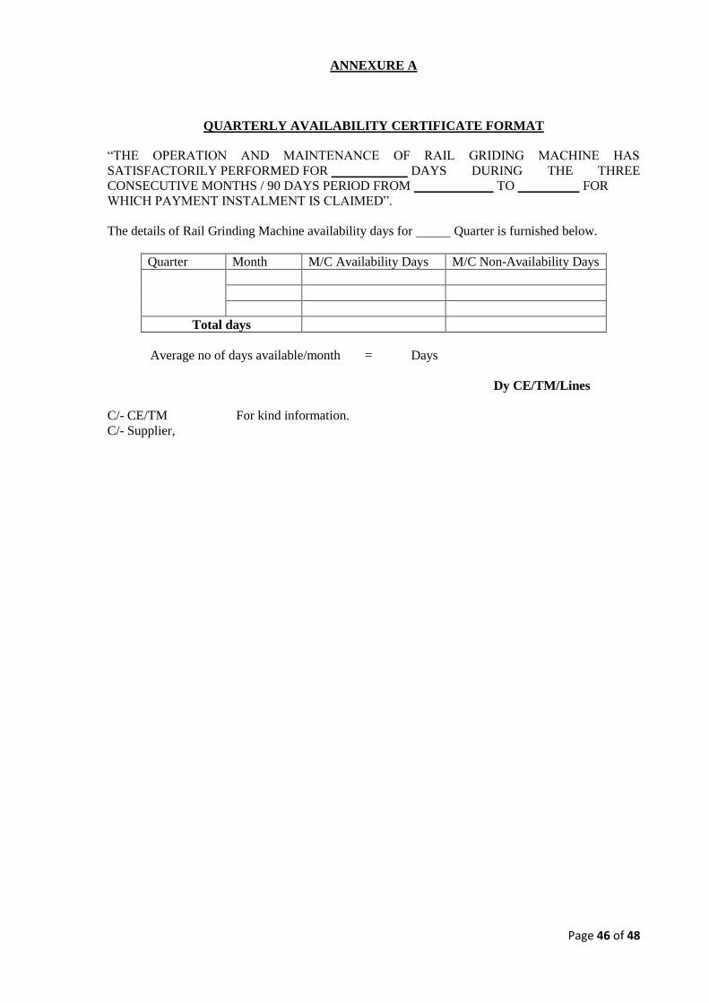
Page 46 of 48
ANNEXURE A
QUARTERLY AVAILABILITY CERTIFICATE FORMAT
“THE OPERATION AND MAINTENANCE OF RAIL GRIDING MACHINE HAS
SATISFACTORILY PERFORMED FOR DAYS DURING THE THREE
CONSECUTIVE MONTHS / 90 DAYS PERIOD FROM TO FOR
WHICH PAYMENT INSTALMENT IS CLAIMED”.
The details of Rail Grinding Machine availability days for Quarter is furnished below.
Quarter Month M/C Availability Days M/C Non-Availability Days
Total days
Average no of days available/month = Days
Dy CE/TM/Lines
C/- CE/TM For kind information.
C/- Supplier,
Page 47 of 48
ANNEXURE B
HALF YEARLY PENALTY DEDUCTION CERTIFICATE FORMAT
“AMOUNT OF PENALTY DEDUCTION TO BE MADE AS PER CLAUSE NO 1.11 OF THE
TECHNICAL SPECIFICATION TO RAILWAY BOARD CONTRACT AGREEMENT NO
IS ”.
Dy CE/TM/Lines
C/- CE/TM For kind information.
C/- Supplier,
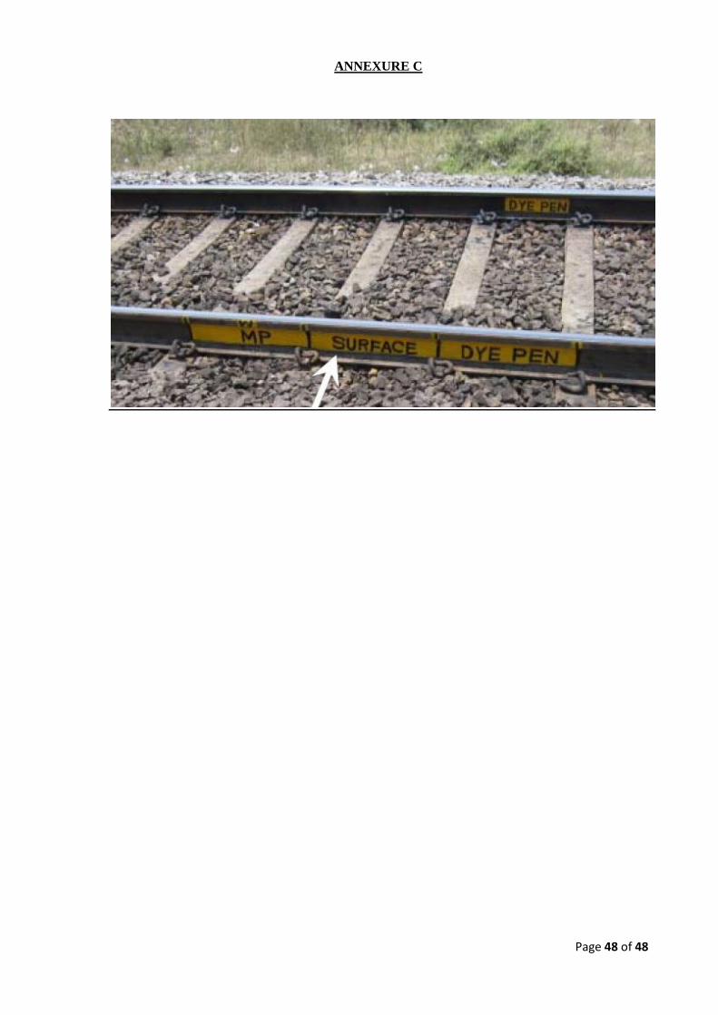
Page 48 of 48
ANNEXURE C


![Application of grinding to reduce rail side wear in ...eprints.whiterose.ac.uk/128105/1/Wear 2018 Rail... · contact model to optimize wheel and rail profiles [2, 3]. Choi et al](https://img.pdfslide.net/doc/110x75/606398e0b90c2e7e52186011/application-of-grinding-to-reduce-rail-side-wear-in-2018-rail-contact-model.jpg)