Embed Size (px)
Citation preview
AN.NUALTECH NICAL fl0SYMPOSIUM
"NAVY IN THE NINETIES - TREND AND TECHNOLOGY"
DT!CLELECTE E0S.•:•.AUG 25 1987i
cv, C00 D
Approv47c! -r~~
REACTIVATION OF 16-INCH THREE GUN TURRETS IN THE BATTLESHIPby: Art Romano
ASSOCIATION OF SCIENTISTS AND ENGINEERS OF THE NAVAL SEA SYSTEMS COMMAND * DEPARTMENT OF THE NAVY e WASHINGTON, D.C. 20362
Reactivation of 16-Inch Three Guii Turrets
In the Battleships
Arthur R. Romano N
DirectorGun Division
Naval Sea Systems CommandMarch 1987
I.
The views expressed herein are the personal opinions of the author and are nctnecessazily the official views of the Department of Defense or of a militarydepartment.
NTIS C R,&I IDT;C TAB F]
y........................ -
DB Y t .ib '. :,/ . .
S.--_*•1 . . .. ... .. . .... ..
D i ; 1Y", "'
;:• ,, .'.;
TABLE OF CONTENTS
PAGE
TABLE OF CONTENTSLIST OF TABLES iiLIST OF ILLUSTRATIONS iii
ABSTRACT II INTRODUCTION 2
HISTORY 3 %DESCRIPTION OF 16-INCH TURRETS 3OPERATION OF 16-INCH TURRETS ONBOARD BB-61 CLASS 6
II REACTIVATION 9
BASIC REACTIVATION METHOD USED FOR 16-INCH TURRET 9OSCILLATION OF ELEVATION DRIVE q
HYDRAULIC SYSTEM CLEAN-UP 12BREECH OPERATING VALVE 13VELOCIMETER 1 3SEQUENTIAL FIRING OF GUNS IN A TURRET 14
Il 16-INCH GUN BARREL 16EXISTING 16-INCH GUN BARREL DESIGN 2016-INCH GUN BARREL INSTALLATION/EXCHANGE 22RELINING OF A 16-INCH GUN BARREL 23NEW l6-iNcH GUN BARREL DESIGN 23
iV RELATED PROGRAMS 2t
V SUMMARY 25
APPENDIX 26
A UNITED STATES NAVY BATTLESHIPS 26
S.'
V
irU-
5,
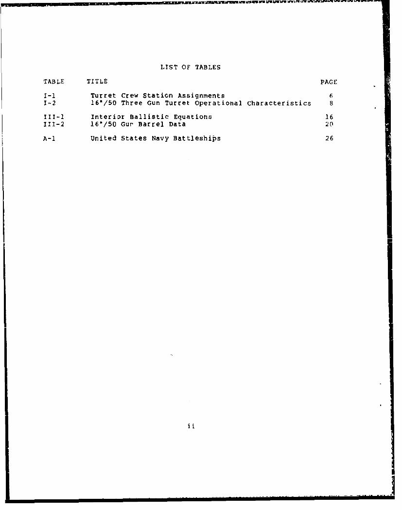
LIST OF TABLES
TABLE TITLE PAGE
I-i Turret Crew Station Assignments 61-2 16*/50 Three Gun Turret Operational Characteristics 8
I1-1 Interior Ballistic Equations 16111-2 16"/50 Gur Barrel Data 20
A-1 United States Navy Battleships 26
ii
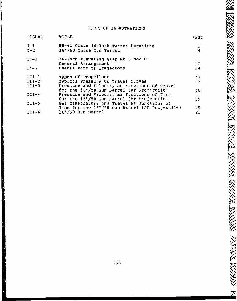
LI( T OF ILLUSTRATIONS
FIGURE TITLE PAGE
1-i BB-61 Class 16-Inch Turret Locations 21-2 16"/50 Three Gun Turret 4
1I-i 16-Inch Elevating Gear Mk 5 Mod 0General Arrangement 10
11-2 Usable Part of Trajectory 14
III-1 Types of Propellant 17 -rOp111-2 Typical Pressure vs Travel Curves 17111-3 Pressure and Velocity as Functions of Travel 18
for the 16"/50 Gun Barrel (AP Projectile) 18111-4 Pressure Fnnd Velocity as Functions of Time
for the 161/50 Gun Barrel (AP Projectile) 19111-5 Gas Temperature and Travel as Functions of v
Time for the 160/50 Gun Barrel (AP Projectile) 19• -(111-6 16"/50 Gun Barrel 21
I.
. -
ili
%N.'
t.'%
S! I I I I I I
PROPOSED PAPER FOR THE 1986
ASSOCIATION OF SCIENTIS;TS AND ENGINEERS SYMPOSIUM
Reactivation of 16-Inch Three Gun Turrets
Abstract 1/According to Jane's Fighting Ships, the IOWA class are the most
heavily armored Uvi-ted$ tewar ships lver constructed.
% I1A, As a part oi4*e program to increase U1. Naval power, the four
---BB61 class ships in the inactive reserve fleet commencedl,reactivation and modernizationSbeginning with BB-62.1i--•1-.
The 16-inbh guns carried by the ships are the largest guns everput to sea by the U. S. Navy and are the largest in existence in theworld today. For a'listing of all Battleships ever built by theUnited Sta~t;s see Appendix A.
Ieactivation of the 16-ine4ý'turrets was accomplished with fewmajor problems because of the'care with which they were preservedwhen deactivated. The reactivation effort basically involvedcleaning, reassembling, adjusting, arid testing each cvmpOineriL Of theturret individually until all componeits were operating and thentesting the entire gun as a unit.
Reactivation of the 16-inp'guns rekindled thinking about basicmajor caliber gun system opeiation. Studies and dusign improve-ments have been completed on measuring the muzzle ve)ocity of theprojectile, and reducing the wear of the gun barrel through additionof a wear reducing jacket on the propellant charge. Additionallonger range programs are underway to extend the range and accuracyof the 16-inch gun.
With the reactivation of the 153/50 Three Gun Turrets the U. S.Navy has gained a unique major weapon systenm at a fraction of thecost to design and build a comparable system.
REACTIVATION OF16-/50 THREE GUN TURRET
I INTRODUCTION
Since 1981 when the U.S. Navy began reactivation of the USS NEWJERSEY, controversy has surrounded this program. However,controversy has surrounded battleships 3ince the first battleshipwas built. Controversy can be traced to the definition of"battleship". According to the Third New International Dictionary,Unabridged Edition, dated 1981, a battleship is defined as:
Ma warship of the largest and most heavily armed andarmored class usually having at least 10-inch armorand carrying in the main battery, guns of 12-inch orlarger caliber."
However, this definition implies that the battleship is superior toall other ships, which is probably the cause of most of thecontroversy. It is the larger caliber guns and heavy armor on abattleship which makes them unique an asset to the Fleet.
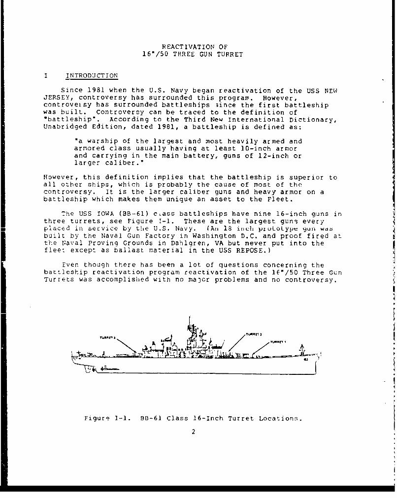
The USS IOWA (BB-61) c~ass battleships have nine 16-inch guns inthree turrets, see Figure 1-1. These are the largest guns everyP [aced iU SELvi1V by th'e U.S. Navy. (An 1i incli pLULUoype gull Wdibuilt by the Naval Gun Factory in Washington D.C. and proof fired atthe Naval Proving Grounds in Dahlgren, VA but never put into thefleet except as ballast material in the USS REPOSE.)
Even though there has been a lot of questions concerning thebattleship reactivation program reactivation of the l6/50 Three GunTurrets was accomplished with no majcr problems and no controversy.
TRAT.mr 3~tNI
Figure I-1. BB-61 Class 16-Inch Turret Locations.
2
History
Guns have been on ships for centuries but it wasn't until the1800's that they became useful for anything but shooting at pointblank range. The British fired the first rifled gun in the1850's.
Rifling is a series of spirally formed grooves and lands cut inthe inside of the barrel from the chamber to the muzzle. It inducesa spin to the projectile along its longitudinal axis when it leavesthe barrel. Longitudinal rotation of the projectile providesstability in flight which permits the use of longer and heavierprojectiles. This allowed guns to obtain vastly increased range,accuracy, and projectile penetration of the target. Old smoothborecannons could fire only round shot. ahe weight of the old sphericalprojectile was limited by size thus making them more affected bywind and air resistance than more massive ones.
Ramming large caliDer ammunition from the muzzle was excessivelydifficult if the projectile fit the rifled bore closely, and therifling was useless if it didn't.
The key to making effective and practical rifled guns lay indevelopment of effective mechanisms to permit loading from breechend rather than the muzzle end. The first breech loaded gun was
Large caliber gun development then progressed rapidly. A 16"/50caliber gun was first designed and proof fired by the U.S. Navy in
1918. Due to the London Naval Agreement (Arms Limitation), furtherdevelopment and construction was set aside. Work on a new 16"/50caliber gun began in 1938 after the Arms Limitation Agreement hadexpired. These guns were to be installed in six IOWA class and fiveMONTANA class ships to be built in the 1940's. USS IOWA, (BB61),USS NEW JERSEY, (BB62), USS MISSOURI, (BB63), and USS WISCONSII,(BB64,, were the only ships built. After World War II, these shipswere d!commissioned briefly, then reactivated for the Korean War.in the late 1950s, these ships were again ruothballed. During theVietnam War, the USS NEW JERSEY was reactivated in 1967 anddeactivated in 1969. In 1981 the current battleship reactivationprogram began. The USS NEW JERSEY, BB62 was recommissioned in 1983;USS IOWA, BB61 in 1984; and USS MISSOURI, BB63 in 1986. USSWISCONSIN, BB64 is scheduled to be recommissioned in August 1988.
Description of 16-:nch Turrets
Turrets I, II and III of each ship are closely similar. Eachhas a gun house mounted above a :onical and cylindrical structure(greatest dia. 35 ft. 1.0 in.). Each such rotating assemDly isprotected by heavy armor plate on the front, sides, rear, and roof
3
CU NH OUS E
STRUECTUR.E
POWDF Et FANOLI
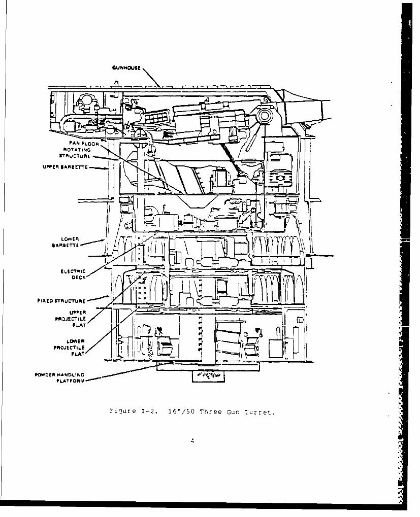
Fi&ie1-. 6/S Tre unTrrt
ELECTRI
of the gun house, and below the shelf plate (gun house floor) isenclosed within fixed barbette of heavy plate of cylindrical form.The barbette and armor deck plates enclose and protect the roller
path and its cylindrical-conical foundation (37 1/4 ft. dia.,max.). The rotating structural is supported from the roller path bya roller carriage composed of 60 large steel rollers mounted in 12cage sectors of five rollers each. The carriage is locatedimmediately below the pan floor (bottom of gun pockets) and thus tieelectric equipment deck, projectile handling levels and powderhandling floor are suspended from the carriage. Differences inheight of structures result in varying space allotments forprojectile stowage and differing heights of lift for powderservice. All other space divisions are virtually the same in allturrets. Turret subdivisions provide separate flameproofedcompartments for the three guns, two sight stations, and the rangefinder turret officer's station; gun compartment subdivisions extcn(Ito the pan floor.
The 16"/50 caliber turret consists of equipment on six separatelevels, see Figure 1-2. These are (i) gunhouse, (2) pan floor, (3)electric deck, (4) upper projectile flat, (5) lower projectile flatand (6) powder handling platform.
1. The gunhouse is 50.63 feet long with a maximum width of 36
feet which is mounted above and attached to the rotating structure.The armor plates of the gunhouse range in thickness from 7.25 inchesto 17 inches. The gunhouse is comprised of the turret officercontrol booth, the gun compartments, and the sight station. All ofthese compartments are separated by flametight bulkheads. The aftoverhang of the gun house contains the only entrance hatches to theturret officer's booth from the weather deck. Located in the uoot-hare the auxillary computer, rangefinder, turret communications andpowered equipment for the rammer. The three separate guncompartments have separate controls and equipment for servicing theindividual guns. The two sight stations contain duplicate equipmentfor the operation of the turret optical sights by the pointers,trainers and sight setters.
2. The pan floor contains the pockets into which the breechesof the guns are depressed as the guns aLe elevated. It alsocontains part of the elevation machinery.
3. The electrical deck is the third level below the gunhouse inwhich are located the three gun layers and the turret trainerstations, and the electric-hydraulic machinery neuessary to move theguns in elevation and the turret in train.
4. The next two levels are the upper and lower projectilesflats where projectiles are stored. Here the projectiles are takenfrom stowages, loaded into hoists and lifted up into the gun roomn.Turret 2 only, has a third level that does not rotate whereprojectiles are stored.
5
5. The bottom level is the powder handling platform. Sur-rounding this flat, outside of the turret, are the powder stowagemagazines. The bags of powder are passed from the magazines throughflameproof scuttles into the handling platforms. Here six bags areloaded into one of three elevator type powder hoist cars fordelivery to one of the gun rooms.
Operation of 16-Inch Turrets Onboard BB-61 Class
Ships and turret design arrangements permit two separate routesper turret to be utilized for moving ammunition from the main deckoutside the turret to stowed positions in the magazine andprojectile flats. Each projectile is lowered through hatch openingsin the ammunition loading trunk to an annular handling space, thenhoisted into the lower or upper projectiles flat level where it islashed in vertical stowage. Similarly, the powder can is strikeddown into the powder magazine and stored in cordwood style racks.
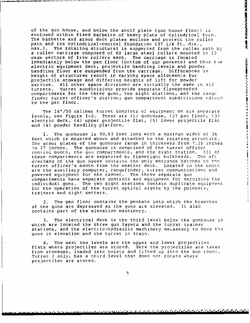
During firing, the 16-inch 3-gun turret is operated with aminimum crew of 77 men inside th? turret. Station assignments forthe turret crew are ordinarily as listed in Table I-1.
Table 1-1. Turret Crew Station Assignment:
Statlon Location Station LocationTurret offPcer ......... o Powder-hoist Top, powde-Turret officer's talker. operators (3)..... trunksTurret captain .......... RangefinderComputer operators (2). and Turret Gun layers (3) ..... MachineryRangefinder operator .... Officer's Gun train operator. floorRanaefinder pointer ..... compartmentRangefinder trainer ..... Projectile-hoistTalker .................. operators (3) .....
Projectile-ringSight trainer, right....) operator .......... Projectile-Sight pointer, right.... Right sight Shellmen (9) ....... handlingSight settei:, right..... station Electrician ........ floor (each
Shell-deck P.O..... level)Sight trainer, left.....Sight pointer, left..... Left sight Powder-door Powder-Sight Setter, left ...... station operators (3) ..... handling
Powder passers (9). floorPlugmen (gun captains)(3) Handling-room P.O..Cradle operators (3)....Rammer operators (3).... 'Gun roomsPrimermen(3) ............
In addition, there are 6 powder passers in the annular space betweenthe powder-handling room and the magazines, and 12 powler passers inthe magazines.
6

With the turret in all respects ready to fire and the powermachinery in operation, the first command is: "Fill the powdertrain; fill the projectile hoists.' At this command the necessarypowder tanks in the magazines are opened using specially designedwrenches; powder is passed through the scuttles to the lowerhandling room; the powder cars are filled and raised to the top cfthe hoists. Ordnance safety precautions require that in eachflametight stage of the ammunition train, not more than one chargeper gun (for the guns being supplied through that stage) shall beexposed or allowed to accumulate. Simultaneously theprojectile-handling room crews are loading the projectile hoistswith the required type of projectiles.
This command further implies that whenever an empty powder caris returned to the lower handling room, or that wienever an emptystage in the projectile hoist appears, the crew reloads immediately.
The first command to the gunroom crew is "Load." The guncaptain, on the loading platform, unlatches the breech-operatinglever and pushes it down. The primerman, under the breech, assiststhe gun captain in locking the breech down. The gun captain wipesthe mushroom and inspects to see that the bore is clear. As soon a-the "Bore clear" signal is given, the gun captain shits off the gasejector valve and signals the cradle operator to span the tray(lower it to loading position).
At the same time the primerman inserts a primer into the openfiring lock. The rammer operator rams the projectile until it isseated and withdraws the rammer as he opens the powder hoist door.The powder-car operator tilts one of the powder-car trays, and 3bags of powder roll across the door onto the spanning tray. The guncaptain and cradle operator guide the powder bags across the doorand space them out on the spanning tray. The powder car lowersabout 23 inches and stops automatically, and the remaining threebags of powder are rolled onto the spanning tray.
The rammerman closes the powder-car door and carefully rams thlesix powder bags to place the rear-most bag not more than 4 inchesfrom the mushroom when the breech is closed. The cradle operatorfolds the spanning tray as soon as the rammer is withdrawn. Thegun captain releases the breech hold-down latch and opens the airvalve to the closing cylinder. He then latches the operating leveras the plug rotates to the closed position. The gun captain stepsoff the loading platform and operates the "ready' switch to signalthat the gun is loaded and to bring the gun to gun order position.The gun is then fired either by a remote signal or in localcontrol. The operational characteristics of the 16*/50 Three GunTurrets on the BB-61 class Battleships are given in Table 1-2.
7
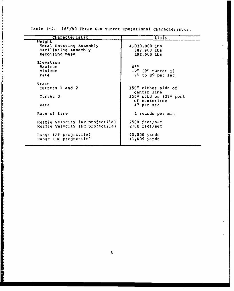
Table 1-2. 16'/50 Three Gun Turret Operational Characteristcs.
Weight Characteristic Limit
Wegh
Total Rotating Assembly 4,030,000 lbsOscillating Assembly 387,900 lbsRecoiling MAss 292,000 lbs
ElevationMaximum 450Minimum -2o (00 turret 2)Rate 70 to 80 per sec
TrainTurrets I and 2 1500 either side of
center lineTurret 3 1500 stbd or 1250 port
of centerlineRate 40 per sec
Rate of fire 2 rounds per min
Muzzle Velocity (AP projectile) 2500 feet/secMuzzle Velocity (HC pro3ectile) 2700 feet/sec
Range (AP projectile) 40,000 yardsRange (HC prcjectile) 41,000 yards
8i
11 REACTIVATION
3asic Reactivation Method Used for 16-Inch Turret
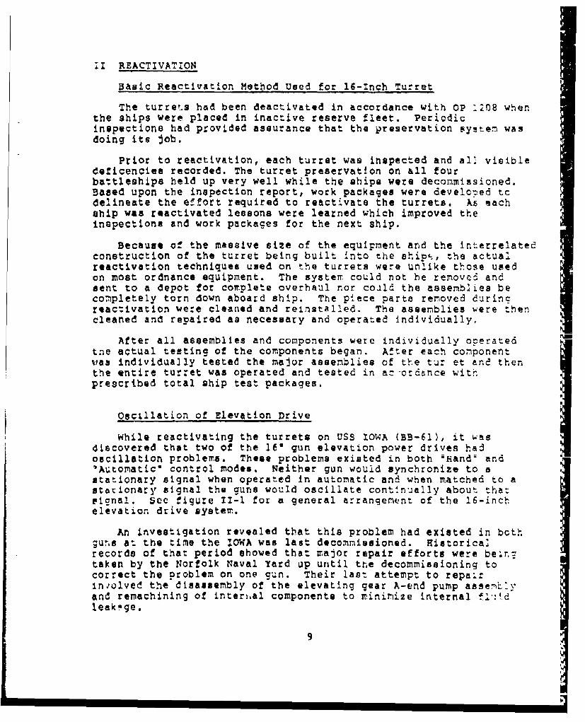
The turrets had been deactivated in accordance with oP :208 whenthe ships were placed in inactive reserve fleet. Periodicinspections had provided assurance that the preservation system wasdoing its job,
Prior to reactivation, each turret was inspected and all visibledeficenciea recorded, The turret preservation on &ll fourbattleships held up very well while the ships were decommissioned.Baaed upon the inspection report, work packages were developed tcdelineate the effort required to reactivate the turrets. As eachship was reactivated lessons were learned which improved theinspections and work packages for the next ship.
Because of the massive size of the equipment and the interrelatedconstruction of the turret being built into the ship,ý, the actualreactivation techniques used on the turrets were unlike those usedon most ordnance equipment. The system could not he renove& andsent to a depot for complete overhaul nor could the assemblies becompletely torn down aboard ship. The piece parts removed durincreactivation were cleaned and reinstalled. The assemblies were thencleaned and repaired as necessary and operated individually.
After all assemblies and components were individually operatedtne actual testing of the components began. After each componentwas individually tested the major assemblies of the tur et and thenthe entire turret was operated and tested in ac:crdance withprescribed total ship test packages.
Oscillation of Elevation Drive
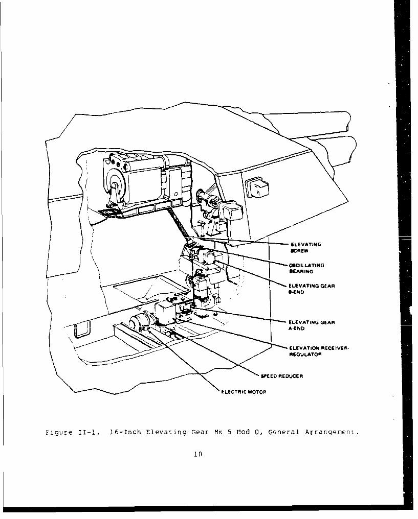
While reactivating the turrets on USS IOWA (BB-6l), it wasdiscovered that two of the 16" gun elevation power drives hadoscillation problems. These problems existed in both 6Handý and'Automatice control modes. Neither gun would synchronize to astationary signal when operated in automatic and when matched to astationary signal the guns would oscillate continually about tha:signal. See figure 1I-1 for a general arrangement of the 16-inchelevation drive system.
An investigation revealed that this problem had existed in both;urs at the time the IOWA was last decommissioned. Ristorica]records of that period showed that major repair efforts were beinztaken by the Norfolk Naval Yard up until the decommissioning tocorrect the problem on one gun. Their last attempt to repairinjolved the disassembly of the elevating gear A-end pump assen~lyand rernachining of internal components to minimize internal fl.'.dleakage.
9
N0
ELEVATINOGE
ELEVATING GEAR
ELEVATION RECEIVER-
REGULATOR
SPEED REDUCER
ELECTRIC MOTOR
Figure II-i. 16-Inch Elevating G-ear Mk 5 M~od 0, General ArrangernenL.
The effects of long term deactivation made these problems evenmore difficult to solve. First, although there were experiencedtechnicians to work the problems, only a few had past workexperience on this gun system and most of these people hadn't beennear this equipment for over thirty years. Accordingly, there wasno one who had a complete understanding of the total interrelation-ship associated with this equipment's operation. Prior to beginningwork on the problem, engineering data had to be gathered i.e., mainsystem and control system pressure data, system internal leakagedata, and system operating response data, to fully evaluate theeffects of the many adjustments required to set up the equipment.In addition, many volumes of technical manuals, old weaponspecifications, etc. were researched in the process of thisinvestigation. Accordingly, there was a necessary "learning period".Secondly, a preservative (cosmoline), which was used to preserve theequipment during deactivation, was a major problem that hindered theinvestigative work. The preservative, because of the long terndeactivation period, had become hardened, making it difficult toremove. As the systems were reactivated and operated, thispreservative would continually work loose. This material would thenclog orifices, etc., in the Servo Control System causing erraticequipment operation which complicated the investigative process.
Eventually, the source of the problem was pinpointed on bothguns. For one of these guns, it meant the replacement of a ma3orassembly - the A-end pump. (The other gun was corrected byreplacing a major sub-assembly and the fine adjustment of theregulator assy.)
The replacement of this major assembly was an enormtusevolution. This unit is installed inside the turret on what iscalled the *electric deck'. This is a compartment directly belowthe gun pit.
In this area are housed the Power Drive Assemblies for ELEVATION(3), TRAIN (1) and PROJECTILE HOIST (3) systems. It is a verycongested area. There are three access holes through whichequipment can be removed from this area. These holes are coveredwith a one inch steel plate. In all cases these plates haveequipment that is mounted or routed over them. Therefore, beforethe plates can be removed, a substantial amount of equipmentdisassembly was required to clear a path for the removal of theseaccess plates.
On the center gun of turret two, the major assembly to bereplaced was the elevating gear A-end pump. The assembled size ofthis unit is approximately 55 inches high by 30 inches deep by 36inches wide. The access hole used to remove this unit from theelectric deck was only 25 inches by 30 inches in size. Therefore to
1i
remove the A-end assembly, the exterior mounted sub compone:nts hadto be removed and the A-end disassembled Tnto two conponents: (1)Pump and (2) Control Box. From the upper projectile shell deck theunits were lowered through the turret ammunition storage trunks toan outer annular powder handling space at the base of the turret.From there the units were moved aft to the ship's stern via themonorail through the main OBroadw4ay" passageway. There the unitswere hoisted onto the fantail and then off the ship. This sameprocedure can be used to remove many of the other equipment (exceptturret train components) should the need arise.
A final report of the gun oscillation problem which documentsthe actions taken to r6pair these problems and the lessons learnedwhile working the problem was published by NAVORDSTA Lousiville(NOSL R-378).
Hydraulic System
When the battleships were originally deactivated, the hydraulicsystems in the turrets were preserved by filling them with corrosionpreventive compound MIL-C-16173 Grade 2 and then drained. This lefta preservative coating on all internal surfaces in the hundreds ofpipes and hydraulic components of each turret. Because of the 30years storage since these systems were originally preserved, aczirni e 4n f- amo un t I iof the rp r....... 1 v e a dt rir to tVe^ W__ h'*$~ ~f '•,, Th ring to .... ifient al i
surfaces had hardened and remains within the system even afterrepeated flushings. Even today this residual material continues tobe broken loose as the systems are operated. The residue causesproblems when it lodges in the small orifices and ports in the trainand elevation control systems.
To correct this problem a large capacity 0.5 micron filtersystem with an integral motor/pump assembly was installed on eachtrain and elevation unit during reactivation to continuously filterthe fluid during train and elevation operation. These units areoff-line low pressure filters mounted in a recirculating loop on thereservoir. The filtration system can operate independent of trainand elevation operation since it can filter sump tank oil when thedrives are shut down. Fluid is drawn from the existing drain portin the tanks and the filtered fluid returned into the top of thetank.
An off-line low pressure filter mounted in a recirculating loopavoids the problems caused by system flow and pressure surges byplacing the filter on a separate loop with its own constant flow,low pressure pump to Lecirculate fluid from the reservoir. Thisarrangement provides an ideal, steady-state environment for thefilter by isolating it from system flow-and-pressure variations. inaddition, filtration in this location will not impede system flowunder any circumstances, because flow through the filter is provided
12
by a separate pump, and is totally independent of system flow.Consequently, continuous filtratioll can be provided by recirculationof the reservoir even when the hydraulic system is not inoperation. More efficient contamination control can also beprovided in this location, since very fine filtration can beachieved without any restriction on system flow. Since the systemfluid ultimately passes through the filter many times, 0.5micrometer cartridges in this location provide a high level of fluidcleanliness.
Breech Operating Valve
In reactivation of a complex forty-five year old weapon systemlike the 16*/50 Three Gun Turret you might expect a lot of thingsnot to operate within original design specifications. However,there was only one item on the 16'/50 turret which did not operateas required after being reactivated.
This was a commercial pressure reduction air valve installed onthe 16-inch Breech Mechanism to regulate the air pressure to thebreech closing control valve. Because of deterioration from ace anduse, all of the original valves were not able to operate reliarlv"after reactivation. The old valve would not hold the pressureadjustment for a long time.
To eliminate this problem a new commercial pressure reducingvalve was found which was a direct replacement for the old valve.The new valve is being installed on the 16-inch turrets by ORDALT15515. Repair kits are commercially available to repair the newvalves. These repair kits are being added to the supply system toassure logistic support for the new valve.
Velocimeter
Because of the desire to increase the accuracy of 16"/50 ouns,velocimeters were installed on the battleships. A velocimeter wasplaced on the top of each turret in line with the center gun. Fromthat position the velocimeter determines the velocity of theprojectile wnen it leaves the barrel. The exit velocity of the lastprojectile is then transmitted to the fire control computer. Thefire control solution is corrected based upon this data thusimproving the accuracy of the gun. Prior to installation of thevelocimeter the initial velocity of the round was determined bybarrel wear measurement and getting a corresponding correctionfa:tor from a table. The old method was much less accurate andtherefore the gunfire from the turrets was less accurate.
13
The velocimeter works by emit.ting a continuous radar beam whichis reflected by the projectile. By mixing the reflected signal withpart of the transmitter signal, a continuous signal, called adoppler signal is created. The frequency of the doppler signal isdirectly proportional to the velocity of the projectile.
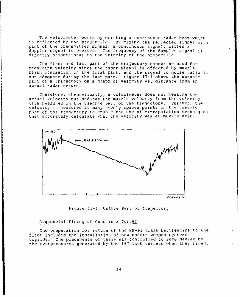
The first and last part of the trajectory cannot be used formeasuring velocity since the radar signal is affected by muzzleflash ionization in the first part, and the signal to noise ratio isnot adequate during the last part. Figure II-1 shows the useablepart of a trajectory on a graph of velccity vs. distance from anactual radar return.
Therefore, theoretically, a velocimeter does not measure theactual velocity but deduces the muzzle velocity from the velocitydata reasured on the useable part of the trajectory. Further, thpvelocity is measured at many evenly spaced points on the useablepart of the trajectory to enable the use of extrapolation techniquesthat accurately calculate what the velocity was at muzzle exit.
V(M/SEC A
I 1 t a I I I I l ! c
DISTANCE IM)
Figure 11-1. Usable Part of Trajectory
Sequencial Firing of Guns in a Turret
The preparation for return of the BB-61 class battleships to thefleet included the installation of new modern weapon systemstopside. The placements of these was controlled to some degree bythe overpressures generated by the 16" inch turrets when they fired.
14
The placement of equipment on the forward part of the ship wasthe most critical. The highest dynamic pressure some equipment hadpreviously experieiced aboard ship was from a 5-inch gun Based uponavailable test data, calculations predicted some forward mountedequipment would see a reflective pressure from surrounding bulkheadsup to 16.7 psi from one 16-inch gun. This pressure was far inexcess of that for which some equipment had been designed and tested.
The problem was further complicated by the fact that over-pressure from multiple guns in a turret is additive.
Since the equipment could not withstand the overpressure fromthe 160/50 guns, the following options were available:
a. Modify the equipment to withstand the overpressure.b. Relocate the equipment.c. Modify the firing sequence of the three guns in a turret.d. Restrict the 16"/50 turret firing arc.e. Do not install the equipment in the areas of the ship which
receive a high overpressure when the guns fire
A combination of options 'c" and "d" were done. The firing arcs ofthe turrets were reduced by relocating the train limit stops.
Modifying the firinc sequence of the three guns in each turretrequired the development of an ORDALT. ORDALT 15034 added agastattime delay relays and attendant rewiring of the firing circuits forthe two outbound guns, while also remoing the firing delay coilfrom the firing circuit for the center gun. The ORDALT wasinstalled on each battleship during reactivation.
15
III 16-INCH GUN BARREL
Existing 16-Inch Gun Barrel Design
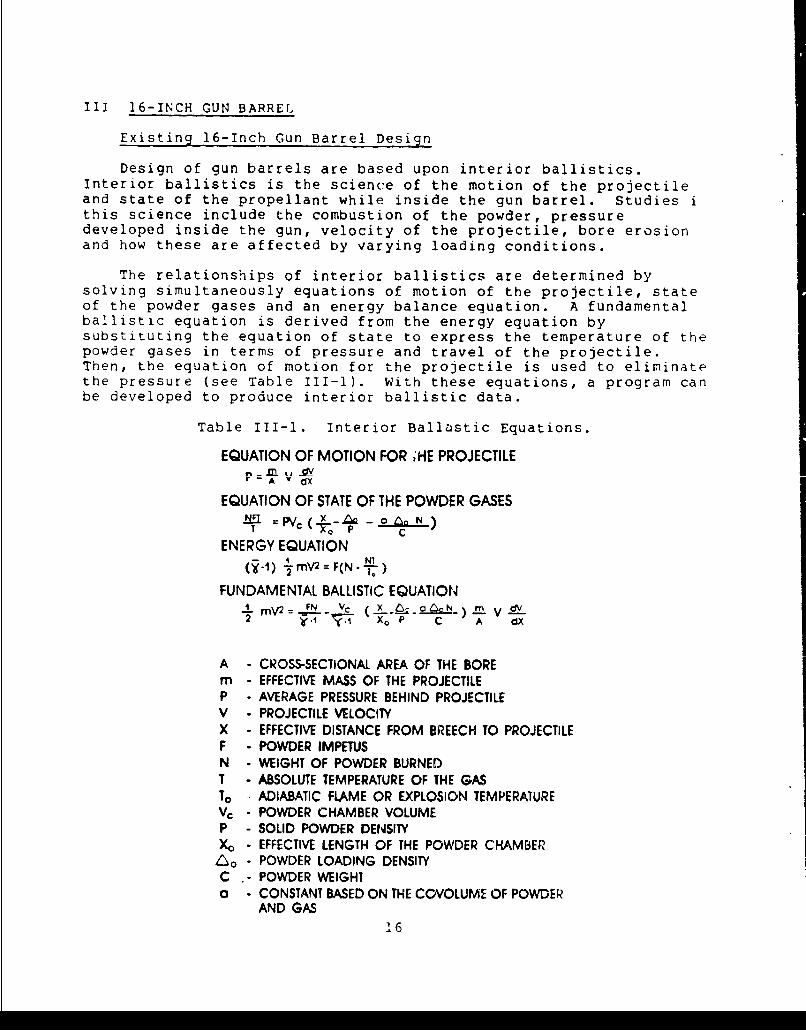
Design of gun barrels are based upon interior ballistics.Interior ballistics is the science of the motion of the projectileand state of the propellant while inside the gun barrel. Studies ithis science include the combustion of the powder, pressuredeveloped inside the gun, velocity of the projectile, bore erosionand how these are affected by varying loading conditions.
The relationships of interior ballistics are determined bysolving simultaneously equations of motion of the projectile, stateof the powder gases and an energy balance equation. A fundamentalballistic equation is derived from the energy equation bysubstituting the equation of state to express the temperature of thepowder gases in terms of pressure and travel of the projectile.Then, the equation of motion for the projectile is used to eliminatethe pressure (see Table III-1). With these equations, a program canbe developed to produce interior ballistic data.
Table III-1. Interior Ballastic Equations.
EQUATION OF MOTION FOR 1HE PROJECTILEr - A v dX
EQUATION OF STATE OF THE POWDER GASES..x -oAoN)-AU =m/ (VT-Z Ln N
ENERGY EQUATION
(i-A) 1 mV2 =F(N. )
FUNDAMENTAL BALLISTIC EQUATIONmV2 = FN VC X 0 N_) ' V dV
i77 KP C A dX
A - CROSS-SECTIONAL AREA OF THE BOREm - EFFECTIVE MASS OF THE PROJECTILEP - AVERAGE PRESSURE BEHIND PROJECTILEV - PROJECTILE VELOCITYX - EFFECTIVE DISTANCE FROM BREECH TO PROJECTILEF - POWDER IMPETUSN - WEIGHT OF POWDER BURNEDT - ABSOLUTE TEMPERATURE OF THE GASTo - ADIABATIC FLAME OR EXPLOSION TEMPERAIUREVc - POWDER CHAMBER VOLUMEP - SOLID POWDER DENSIlYXo - EFFECTIVE LENGTH OF THE POWDER CHAMBERZ*o - POWDER LOADING DENSITYC - POWDER WEIGHTa - CONSTANT BASED ON THE COVOLUME OF POWDER
AND GAS16
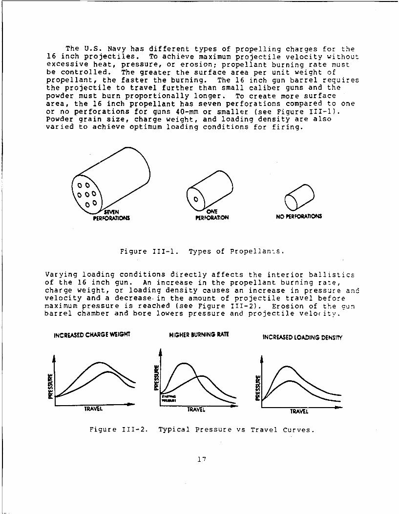
The U.S. Navy has different types of propelling charges for the16 inch projectiles. To achieve maximum projectile velocity withoutexcessive heat, pressure, or erosion; propellant burning rate mustbe controlled. The greater the surface area per unit weight ofpropellant, the faster the burning. The 16 inch gun barrel requiresthe projectile to travel further than small caliber guns and thepowder must burn proportionally longer. To create more surfacearea, the 16 inch propellant has seven perforations compared to oneor no perforations for guns 40-mm or smaller (see Figure III-1).Powder grain size, charge weight, and loading density are alsovaried to achieve optimum loading conditions for firing.
0 SMN 00NEPERFAONS PERK>ORARnN NO PRKWTIONS
Figure 111-1. Types of Propellants.
Varying loading conditions directly affects the interior ballisticsof the 16 inch gun. An increase in the propellant burning rate,charge weight, or loading density causes an increase in pressure andvelocity and a decrease in the amount of projectile travel beforemaximum pressure is reached (see Figure 111-2). Erosion of the aunbarrel chamber and bore lowers pressure and projectile velocity.
INCREASED CHARGE WEIGHT HIGHER BURNING RATE INCREASED LOADING DENSITY
TRAVELL TTR EL
Figure 111-2. Typical Pressure vs Travel Curves.
17
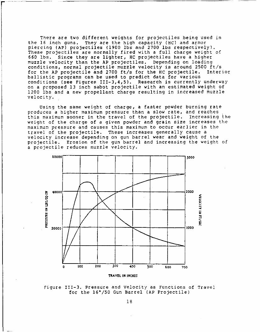
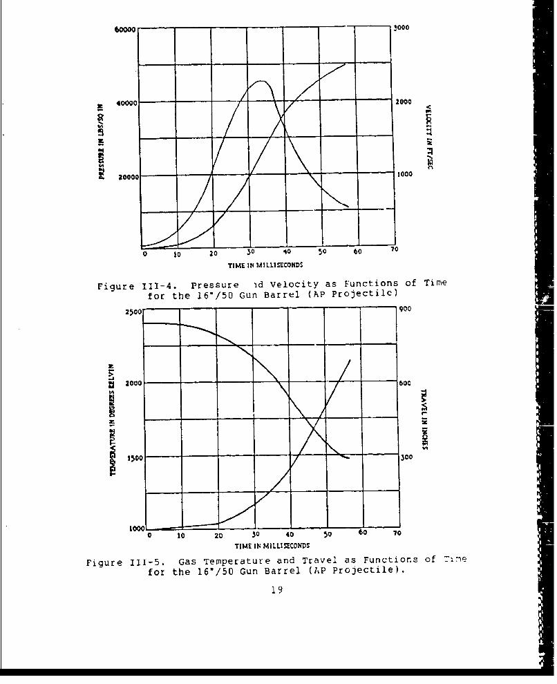
There are two different weights for projectiles being used inthe 16 inch guns. They are the high capacity (Hc) and armorpiercing (AP) projectiles (1900 lbs and 2700 lbs respectively).These projectiles are normally fired with a full charge weight of660 lbs. Since they are lighter, HC projectiles have a highermuzzle velocity than the AP projectiles. Depending on loadingconditions, normal projectile muzzle velocity is around 2500 ft/sfor the AP projectile and 2700 ft/s for the HC projectile. Interiorballistic programs can be used to predict data for variousconditions (see Figures 111-3,4,5). Research is currently underwayon a proposed 13 inch sabot projectile with an estimated weight of1200 lbs and a new propellant charge resulting in increased muzzlevelocity.
Using the same weight of charge, a faster powder burning rateproduces a higher maximum pressure than a slow rate, and reachesthis maximum sooner in the travel of the projectile. Increasing theweight of the charge of a given powder and grain size increases themaximum pressure and causes this maximum to occur earlier in thetravel of the projectile. These increases generally cause avelocity increase depending on gun barrel wear and weight of theprojectile. Erosion of the gun barrel and increasing the weight ofa projectile reduces muzzle velocity.
60000 3000
4000 2 000
z
20000 1000
0 100 200 300 400 500 600 700
TRAVEL IN INCHES
Figure 111-3. Pressure and Velocity as Functions of Travel
for the 16'/50 Gun Barrel (AP Projectile)
18
60000 3000
M40000 2000
S- - o0
20000 1000
0 t0 20 30 40 50 60 70
TIME IN MILLISECONDS
Figure 111-4. pressure Ad Velocity as Functions of Timefor the 16"/50 Gun Barrel (AP Projectile)
2500 - ,900
2000 600
1500 300
IOOOL.[--
0 10 20 30 40 50 60 70
TIME I N MILLISECONDS
Figure 111-5. Gas Temperature and Travel as Functions of Tuine
for the 16"/50 Gun Barrel (AP Projectile).
19
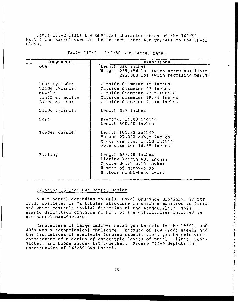
Table 111-2 lists the physical characteristics of the 16"/50Mark 7 Gun Barrel used in the 16-Inch Three Gun Turrets on the BB-61class.
Table 111-2. 16'/50 Gun Barrel Data.
Component DimensionsGun Length 816 inches
Weight 239,156 lbs (with screw box liner)292,000 lbs (with recoiling parts)
Rear cylinder Outside diameter 49 inchesSlide cylinder Outside diameter 23 inchesMuzzle Outside diameter 23.5 inchesLiner at muzzle Outside diameter 18.46 inchesLiner at rear Outside diameter 22.10 inches
Slide cylinder Length 337 inches
Bore Diameter 16.00 inchesLength 800.00 inches
Powder chamber Length 105.82 inchesVolume 27,000 cubic inchesChoke diaTneter 17.50 inchesBore diam?ter 18.35 inches
Rifling Length 682.46 inchesPlating length 690 inchesGroove death 0.15 inchesNumber of grooves 96Uniform right-hand twist
Fvitin, 1-Inch Gun Barrel Design
A gun barrel according to OPlA, Naval Ordnance Glossary, 22 OCT1952, obsolete, is Oa tubular structure in which ammunition is fired Iand which controls initial direction of the projectile.' Thissimple definition contains no hint of the difficulties involved ingun barrel manufacture.
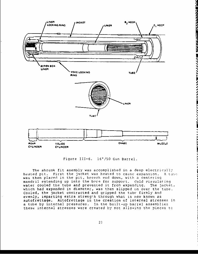
Manufacture of large caliber naval gun barrels in the 1930's and40's was a technological challenge. Because of low grade steels andthe limitations of available forging capabiliLies, gun barrels wereconstructed of a series of concentric layers of metal - liner, tube,jacket, and hoops shrunk fit together. Figure 111-6 depicts theconstruction of 16"/50 Gun Barrel.
I20
LOCINERG MING JAKTLINER 6 OFC1 Hoop
SCREW BOXBOLINER YOKE LOCKING
TUlE
RING
TUBE
REAR I SLIDE CHASE MUZZLE
CYLINDER CYLINDER
Figure 111-6. 16"/50 Gun Barrel.
The shrunk fit asembly was accomplished in a deep electricallyheated pit. First the jacket was heated to cause expansion. A tu!,.was then placed in the pit, breech end down, with a centeringmandril extending up into the bore for support. cold circulatingwater cooled the tube and prevented it from expanding. The jacket,which had expanded in diameter, was then slipped on over the tube.
Cooled, the jacket contracted and gripped the tube firmly andevenly, imparting extra strength through what is now known asautofrettage. Autofrettage is the creation of internal stresses ina tube by internal pressures. In the built-up barrel assembliesthese internal stresses were created by not allowing the pieces tc
21
return to their original diameter after being expapded by heatdurino assembly. Before the assembly process began the outsidediameter of the inside cylinder and the inside diameter of thecylinder being placed over it were machined so that there would bean interference fit after assembly. The addition of hoops on theoutside of the assembly completed the first stage of the gun barrelconstruction. The assembled gun was then ready for conical boringof the tube which preceded the insertion of the liner. In themeantime the liner was turned, bored, measured, and inspected. Thesame process used in the first assembly stage was employed to insertthe liner. The tube with its jacket was placed in the pit, muzzleend down, and expanded under high temperatures. The liner, filledwith water and suspended above the gun, was slowly lowered intoplace. The aun gradually cooled and contracted about the liner.With this process completed, the built-up mass which was to become agun barrel was finished.
Tnis shrink fit assembly technique used to make large calibergun barrels is a very critical process. It is an art requiring awell coordinated crew. The heat input and the flow of the coolingwater had to be controlled exactly to assure the assembly wenttogether properly and as the two mating pieces reached a uniformtemperature mating surfaces did not pull apart longitudinallyweakening the strength of the gun barrel.
Other important operations had to be performed, such asmachining of the bore of the liner to final diameter, and chamberin9 aof th- breech end of the bore for the powder chamber.
7he only remaining operations included machining of the exterior
to final dimensions and machining of the rifling in the liner. Some750 seoarate cuts are required to machine ti rifling in a 16-inchain barrel.
16-Inch Gun Barrel Installation/Exchange
JUSt as ,.nufantul aý 16A-_inoh oun hArrel is considerably more
complex and difficult, the regunning of a 16-inch gun barrel aboarda ship is more difficult than any other gun barrel in the fleettoday.
Before a regunning can be started, shoring must be placedbetween the two decks below the main deck. Then on the top of themain deck shoring must be built up to hold two rails paralleled tothe barrel. Next the barrel is disassembled from the breech andyoke and slowly pulled out of the turret while riding on threespecially made cars on the rails. When the barrel is all the wayout of the turret, it is lifted off of the cars and the new barrelplace4 on the cars and the process reversed.
2?•.1'
S.J
Relining of a 16-Inch Gun Barrel
A 16-inch gun barrel does not have to be scrapped when it isworn out in service because of its built-up type construction.After the barrel is removed from service it is shipped back to amanufacturing facility. There the complete assembly is placed in
the furnace pits used to heat the barrel during assembly. Coolingwater is then piped through the interior of the barrel. While the
assembly is being heated large jacks pull on the liner until it isbroken loose from the assembly. The liner is then removed from the
assembly and a new liner placed into the old assembly. The newassembly is machined internally to become a new gun barrel ready for
proof-firing and issue to the fleet.
New 16-Inch Gun Barrel Design
Because of the superior steels now available and the increased
capabilities of the forging industry, a much simpler 16-inch gin
barrel design is now possible. The new 16-inch gun barrel would be
made from a one piece forging of high strength steel in accordance
with MIL-S-46119 with an elastic limit of 160,000 psi to 180,000 psi
used in all gun barrels currently being manufactured. The monoblock
16-inch gun barrel would have an adapter for interface with the
existing recoil system, slide assembly and yoke assembly, and to
assure proper operation of the turret elevation drive systems.
As an alternative to an all new gun barrel, some addition:0
strength arid wear life can be gained by relining existing wor.
16-inch gun barrels with liners made from MIL-S-46119 steel.
23
IV RELATED PROGRAMS
Three major changes to the 16-inch ammunition used by the BB-61class ships have either been completed or are in the design phase asa rssult of the reactivation program.
To reduce the wear of the gun barrel, which originally had alife of only 300 rounds, a wear reducing jacket is being attached toall full charge propellant bags. The wear reducing agent reducesthe heat input to the barrel which is the major cause of wear of theLarrel.
Tests conducted at the beginning of the battleships reactivationprogram determined that the powder for the 16"/45 guns did notdeteriorate in storage as much as the 16*/50 powder and gave moreconsistent muzzle velocities which meant improved accuracy.Therefore, 16*/45 powder was loaded for use by the battleships whenfiring the 1900 pound projectiles. The heavy 2700 pound armorpiercing projectile can not be fired with the 16'/45 powder becausethe faster burning rate of that powder would result in too high ofpressure inside the gun barrel.
Longer range improvements are also in work for the 16-inch gunsystem. These improvements include 16-inch projectiles, a longerrange 13-inch 5abOL pfojeCt-ilC ard i-provef••. f o ntrol -,stem
components.
24
II
V SUMMARY
All twelve 160/50 turrets on the BB-61 class ships were inexcellent conditions when inspected pricr to reactivation. Thereactivation of these turrets have been accomplished to date with nomajor problems. The biggest effort required to reactivate theturrets have been the cleaning of the preservative from the insideof the hydraulic systems. The equipment had not rusted ordeteriorated since deactivation. Generally a systematic cleaning,reassembling, adjustment and testing was all that was needed toreactivate the turrets.
The 16-inch turret is operated by a 77 man crew who properlytrained can fire two rounds a minute from each of the three guns ina turret. While this firing rate may seem slow compared to moderngun systems, it must be realized that two rounds per minute fro7 t.ethree guns of a turret can put over 16,000 pounds of ordnance on atarget in a minute. A single HC round was able to clear a heli-copter landing zone 200 yards in diameter out of dense, triple-canopy jungle and defoliate trees and undergrowth for another300-400 yards in Vietnam. The rounds created craters 50 feet acrosEand over 20 feet deep. A broadside from an IOWA class ship car,level almost anything standing within a one square mile area. Theseguns were never intended to be fired rapidly but are to be airerdeliberately at targets.
By reactivating the 16-inch turrets the Navy has obtained ahighly capable weapon system which can engage a wide range ofsurface targets in all weather conditions for a long period of timebetter than any other system the Navy has in the Fleet. Even inpeace time the 16-inch turrets on the battleships provide animpressive naval presence.
25
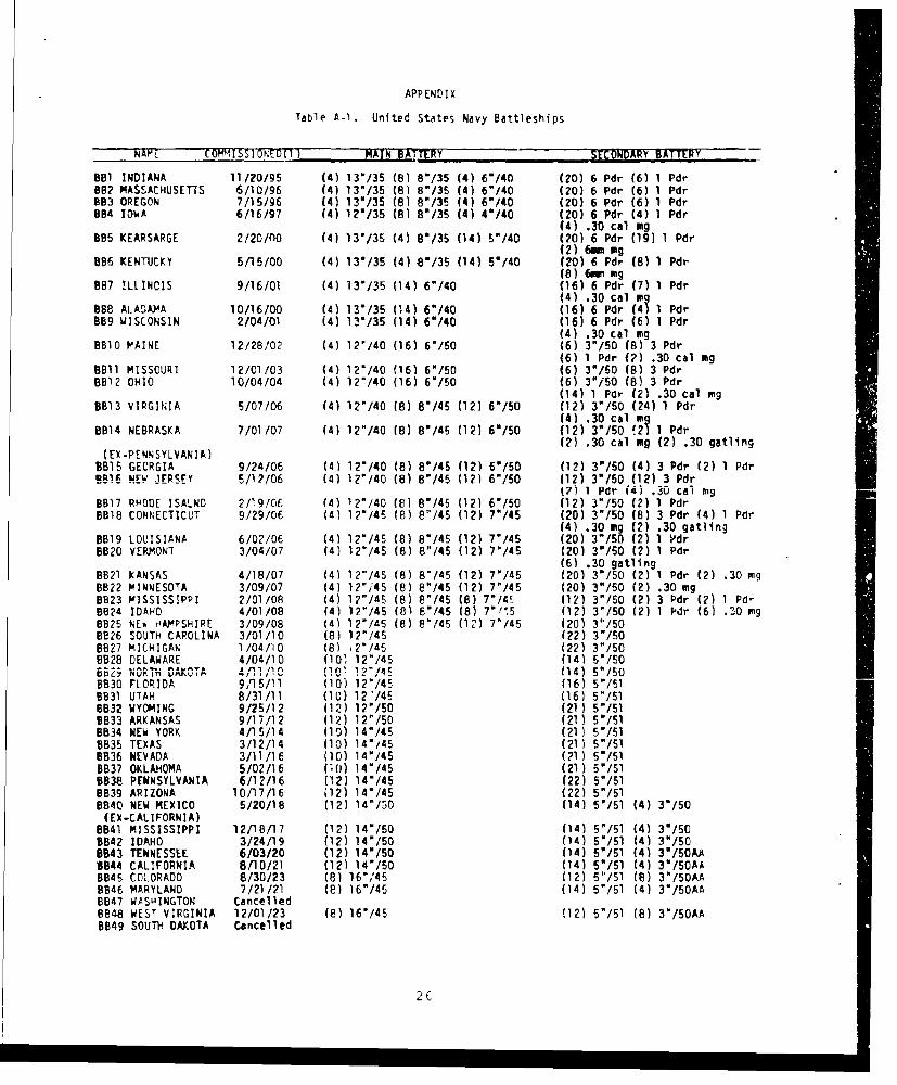
APPENDIX
Table A-1. United States Navy Battleships
NAPE COMMISSIO ED(1) " MAIN BATRLY , SECONDARY BATTERY
BBl INDIANA 11/20/95 (4) 13"/35 (8) 8"/35 (4) 6"/40 (20) 6 Pdr (6) 1 Pdr862 MASSACHUSETTS 6/10/96 (4) 13"/35 (8) 8"/35 (4) 6"/40 (20) 6 Pdr (6) 1 PdrBB3 OREGON 7/15/96 (4) 13'/35 (6) 8"/35 (4) 6"/40 (20) 6 Pdr (6) 1 PdrBB4 IOWA 6/16/97 (4) 12"/35 (8) 8"/35 (4) 4"/40 (20) 6 Pdr (4) 1 Pdr
(4) .30 cal mg885 KEARSARGE 2/20/nO (4) 13'/35 (4) 8"/35 (14) 5"/40 (20) 6 Pdr (19) 1 Pdr
(2) 6m. mg896 KENTUCKY 5/15/00 (4) 13'/35 (4) V/35 (14) 5"/40 (20) 6 Pdr (8) 1 Pdr
(8) 6wu mg8B7 ILLINCIS 9/16/01 (4) 13*/35 (14) 6"/40 (16) 6 Pdr (7) 1 Pdr
(4) .30 cal "gBB8 AiArA)AA 10/16/00 (4) 13'/35 (14) 6"/40 (16) 6 Pdr (4) 1 Pdr889 WISCONSIN 2/04/01 (4) 13*/35 (14) 6"/40 (16) 6 Pdr (6) 1 Pdr
(4) .30 cal wigBBIO PAINE 12/28/02 (4) 12"/40 (16) 6"/50 (6) 3"/50 (8) 3 Pdr
(6) 1 Pdr (2) .30 cal mg8811 MISSOURI 12/01/03 (4) 12'/40 (16) 6"/50 (6) 3"/50 (8) 3 PdrBB12 OHIO 10/04/04 (4) 12"/40 (16) 6"/50 (6) 3"/50 (8) 3 Pdr
(14) 1 Pdr (2) .30 cal mg8813 VIRGINIA 5/07/06 (4) 12"/40 (8) 8"/45 (12) 6*/50 (12) 3"/50 (24) 1 Pdr
(4) .30 cal IgBB14 NEBRASKA 7/01/07 (4) 12"/40 (8) 8'/45 (12) 60/50 (12) 3"/50 f2i 1 Pdr
(2) .30 cal og (2) .30 gatlling(EX-PENNSYLVANIA)
8815 GEORGIA 9/24/06 (4) 12'/40 (8) 8"/45 (12) 6"/50 (12) 3"/50 (4) 3 Pdr (2) 1 PdrW861 NE-J ERSEY 5/12/06 (4) 12"/40 (8) 8B/45 (12) 6-/50 (12) 3"/50 (12) 3 Pdr
(7) 1 Por W4) .30 cai mg8B17 RHODE ISALND 2/19/06 (4) 12'/40 (8) 8"/45 (12) 6"/50 (12) 3"/50 (2) 1 Pdr8818 CONNECTICUT 9/29/06 (4) 12*/45 (8) 8"/45 (12) 7'/45 (20) 3"/50 (8) 3 Pdr (4) 1 Pdr
(4) .30 mg (2) .30 gatlingBB19 LOUISIANA 6/02/06 (41 12"/4S (8) 8"/45 (12) 7"145 (20) 3"/50 (2) 1 Vdr8B20 VERMDNT 3/04/07 (4) 12*/45 (8) 8"45 (12) 7P/45 (20) 3"/50 (2) 1 Pdr
(6) .30 gatlingBB21 KANSAS 4/18/07 (4) 12"/45 (8) 8"/45 (12) 7'/45 (20) 3"/50 (2) 1 Pdr (2) .30 tng8B22 MINNESOTA 3/09/07 (4) 12"i45 (8) 8"/45 (12) 7'/45 (20) 3"/50 (2) .30 mg
BB23 MISSISSIPPI 2/01/08 (4) 12"/45 (8) 8"/45 (8) 7"/4E (12) 3"/50 (2) 3 Pdr (2) 1 Pd-8824 IDAHO 4/01/08 (4) 12"/45 (81 8"/45 (8) 7"'.5 (12) 3"/50 (2) 1 Plr (6) .30 yng8B25 NEo HAMPSHIRE 3/09/08 (4) 12"/45 (8) 8"145 (12) 7"/45 (20) 3"/508826 SOUTH CAROLINA 3/01/10 (8) 12"/45 (22) 3"/50BB27 MICHIGAN 1/04/10 (8) 12"/45 (22) 3"/508B28 DELAWARE 4/04/10 (10, 12"/45 (14) 5"/50H.29...T........ 4,/,1/ (10T 10"/41 (14) 5"/50B830 FLORIDA 9,15/11 (10) 12"/45 (16) 5"/51B831 UTAH 8/31/11 (1U) 12'/45 (161 5"/518B32 WYOMING 9/25/12 (12) 12"/50 (21) S"/518B33 ARKANSAS 9/17/12 (12) 12"/50 (21) 5"/51B834 NEW YORK 4/15/14 (10) 14"/46 (21) 5"/S18B35 TEXAS 3/12/14 (10) 14"/45 (21) 5"/S18836 NEVADA 3/11/16 (10) 140/45 (21) 5"/Sl
BB37 OKLAHOMA 5/02/16 (0) 14"/45 (21) 5"/Sl8838 PENNSYLVANIA 6/12/16 (12) 14"/45 (22) 5"/518B39 ARIZONA 10/17/16 (12) 14'/45 (22) 5'/519B40 NEW MEXICO 5/20/18 (12) 14"/50 (14) 5"/51 (4) 3"/50
(EX-CALIFORNIA)BB41 MISSISSIPPI 12/18/17 (12) 14"/50 (14) 5"/51 (4) 3w/50B842 IDAHO 3/24/19 (12) 14"/50 (14) 5"/51 (4) 3"/508843 TENNESSEE 6/03/20 (12) 14"/50 (14) 5V/51 (4) 3"/50AA8844 CALIFORNIA 8/l0/21 (12) 14"/50 (14) 5"/51 (4) 3"/50AA
B845 COLORADO 8/30/23 (8) 16',45 (12) 5"/51 (8) 3"/50AA8846 MARYLAND 7/21/21 (e) 16"/45 (14) 5-/51 (4) 3"/50AA8847 WASwINGTON Cancelled8948 WEST VIRGINIA 12/01/23 (8) 16"/45 (12) 5"/51 (8) 3"/50AABB49 SOUTH DAKOTA Cancelled
2C
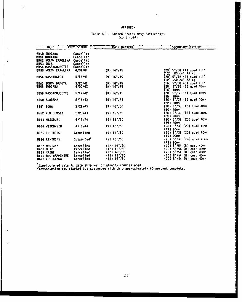
APPENDIX
Table A-1. United States Navy Battleships(cor.tinued)
NAIE COMMISSIONED(1) MAIN BATTERY SECONDARY BATTERY
8850 INDIANA CancelledBB51 MONTANA CancelledBB52 NORTH CAROLINA Cancelled5953 IOWA Cancel ledB354 MASSACHUSETnS CancelledB855 NORTH CAROLINA 4/09/41 (9) 16"/45 (20) 5"/38 (4) quad 1.1"
(12) .50 cal AA mgB856 WASHINGTON 5/15/41 (9) 16"/45 (20) 5V/38 (4) quad 1.1"
(12) .50 cal AA mgBB57 SOUTH DAKOTA 3/20/42 (9) 16'/45 (16) 5V/38 (8) quad 1.1"8858 INDIANA 4/30/42 (9) 16"/45 (20) 5/38 (6) quad 40mn
(16) 20mm5859 MASSACHUSETTS 5/12/42 (9) 16*/45 (20) 5"/38 (6) quad 40CmM
(35) 20mm8860 ALABAMA 8/16/42 (9) 16'/45 (20) V/2S (6) quad 40ram
(22) 20amm8961 IOWA 2/22/43 (9) 16"/50 (20) 5V/38 (15) quad 40mi
(60) 20mm8862 NEW JERSEY 5/23/43 (9) 16"/50 (20) 5"38 (16) quad 40mir
(60) 20mmB863 MISSOURI 6/11/44 (9) 16"/50 (20) 5"/38 (20) quad 40mir
(49) 20m8864 WISCONSIN 4/16/44 (9) 16"/50 (20) 5'/38 (20) quad 40mm
(49) 20amm8865 ILLINOIS Cancelled (9) 16"/50 (20) 5"/38 (20) quad 40mcn(49) 20mm9966 KENTUCKY Suspended2 (9) 16"/50 (20) 5iw3 1201 quad 40,v-
("9) 20m"8967 MONTANA Cancelled (12) 16"/50 (20) 5"/54 (8) quad 40mrrBB68 OHIO Cancelled (12) 16"/50 (20) 5"/54 (0) quad 40Wr6869 MAINE Cancelled (12) 16"/50 (20) 5"/54 (8) quad 40-mrB870 NEW HAMPSHIRE Cancelled (12) 16"/50 (20) 5"/54 (8) quad 40iw8871 LOUISIANA Cancelled (12) 16"/50 (20) 5/54 (8) quad 40mrw
lCo•g•issloned date is date ship was originally comitssioned.
"2 Construction was started but suspendeu with ship approximately 60 percent complete.
'7I


![TRAINING REGULATIONS - Hydraulic excavator... · 2020-01-16 · Heavy -Equipment Operation [Hydraulic Excavator] NC II TRAINING REGULATIONS CONSTRUCTION SECTOR TECH NICAL EDUCATION](https://img.pdfslide.net/doc/110x75/5e5473488400f878c010815b/training-hydraulic-excavator-2020-01-16-heavy-equipment-operation-hydraulic.jpg)