Embed Size (px)
Citation preview
Surface & Coatings Technology 203 (2009) 1494–1501
Contents lists available at ScienceDirect
Surface & Coatings Technology
j ourna l homepage: www.e lsev ie r.com/ locate /sur fcoat
Anodic films containing polyaniline and nanoparticles for corrosion protection ofAA2024T3 aluminium alloy
O. Zubillaga a,⁎, F.J. Cano a, I. Azkarate a, I.S. Molchan b, G.E. Thompson b, P. Skeldon b
a INASMET-Tecnalia, Mikeletegi Pasealekua 2, E-20009 Donostia-San Sebastián, Spainb Corrosion and Protection Centre, School of Materials, The University of Manchester, PO Box 88, Manchester, M60 1QD, UK
⁎ Corresponding author. Tel.: +34 943003700; fax: +3E-mail address: [email protected] (O. Zub
0257-8972/$ – see front matter © 2008 Elsevier B.V. Aldoi:10.1016/j.surfcoat.2008.11.023
a b s t r a c t
a r t i c l e i n f oArticle history:
Anodic alumina films conta Received 17 September 2008Accepted in revised form 24 November 2008Available online 3 December 2008Keywords:AnodisingConducting polymerNanoparticlesCorrosion protectionAA2024 aluminium alloy
ining polyaniline and either TiO2 or ZrO2 nanoparticles were electrochemicallysynthesised on an AA2024T3 aluminium alloy by a single step anodising procedure in an oxalic acidelectrolyte. The morphology and composition of the films were examined by SEM, TEM, GDOES and XPS. Theresultant coatings, of thickness about 2.2 μm, displayed a nanoparticle-rich layer in the near surface-regions,of thickness in the range 100–250 nm. Potentiodynamic polarisation behaviour revealed that the polyanilineand TiO2-containing films on the AA2024T3 aluminium alloy show a passive current density two orders ofmagnitude lower than for films with ZrO2 nanoparticles and films without nanoparticles. The coatings withTiO2 nanoparticles, but without polyaniline, showed intermediate behaviour, with a passive current densityone order of magnitude lower than the coatings with polyaniline and TiO2 nanoparticles. The improvedbarrier protection offered by the TiO2 nanoparticle containing coatings is attributed to the presence of thenanoparticle-rich layer formed on the outer part of the coating that blocks access to the pores of the anodicalumina film.
© 2008 Elsevier B.V. All rights reserved.
1. Introduction
Table 1Nominal chemical composition of the aluminium alloy 2024T3
High strength aluminium alloys, i.e. AA2024T3, are commonlyused in aerospace applications after appropriate corrosion controlmeasures. The corrosion mechanisms of AA2024T3 alloy have beenextensively studied and protection treatments developed [1–6]. Forexample, anodising, with subsequent priming and top coating, iswidely employed. Anodising involves electrochemical formation of aprotective anodic aluminium oxide layer over the macroscopic alloysurface. The growth, composition, morphology and performance ofanodic films have been studied extensively for aluminium and itsalloys [7–12]. Additionally, mechanisms of sealing of porous anodicoxide films by hydrothermal treatment have been reported [11–18].
Anodising in chromic acid has been used extensively in theaerospace industry to provide superior corrosion resistance andadhesion performance compared with anodising in other electrolytes.Further, dichromate sealing of anodic films has been shown to behighly effective for corrosion protection [12,17,18]. Due to thecarcinogenic nature and toxicity of hexavalent chromium species,various alternatives have been developed in recent years to replaceconventional anodising in chromic acid. For example, Mourtalier et al.[17,19,20] studied the incorporation of cerium (IV) andmolybdate ionsas inhibitors in anodic films formed in sulphuric acid media. Yu and
4 943003800.illaga).
l rights reserved.
Cao [21] examined the electrochemical behaviour of an AA2024 alloyafter anodising in sulphuric acid media and sealing in a cerium nitratesolution. Further, Kamada et al. [22,23] studied the incorporation ofoxide nanoparticles into alumina films, with anodic oxidation of thealuminium and electrophoretic deposition of nanoparticles performedin a single step. Alumina films with embedded SiO2 nanoparticlesshowed increased capacitance, and improved corrosion protection ofthe substrate. The surface charge and size of the nanoparticles wereconsidered to be significant in enabling their migration to thesubstrate during anodising, with subsequent incorporation into thepores of the anodic alumina films.
A further approach to provide chromate-free corrosion controlmethods is the use of electroconducting polymers that may beelectropolymerised on aluminium substrates by anodic oxidation.However, porous anodic alumina films readily formed in the acidicsolutions that are commonly used for the synthesis of conductingpolymers. The growth of the anodic film acts as a barrier for electrontransfer and, thus, inhibits the polymerisation process. However,
Element Al Si Fe Cu Mn Mg Zn Ti Cr(wt.%) 90–93 0.50 0.50 3.8–4.9 0.3–0.9 1.2–1.8 0.25 0.15 0.10
[3] Handbook of Aluminum and its Alloys, J.R. Davis (ed.), 2a edición, ASM International,EE.UU. (1994).
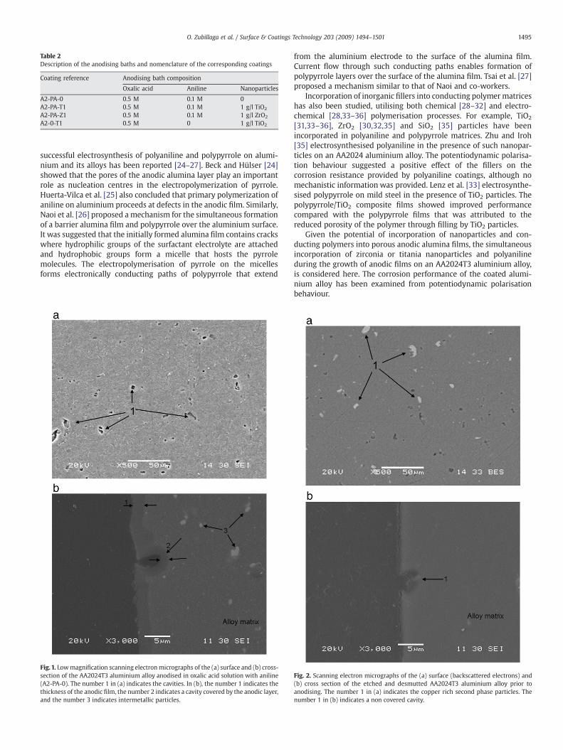
Table 2Description of the anodising baths and nomenclature of the corresponding coatings
Coating reference Anodising bath composition
Oxalic acid Aniline Nanoparticles
A2-PA-0 0.5 M 0.1 M 0A2-PA-T1 0.5 M 0.1 M 1 g/l TiO2
A2-PA-Z1 0.5 M 0.1 M 1 g/l ZrO2
A2-0-T1 0.5 M 0 1 g/l TiO2
1495O. Zubillaga et al. / Surface & Coatings Technology 203 (2009) 1494–1501
successful electrosynthesis of polyaniline and polypyrrole on alumi-nium and its alloys has been reported [24–27]. Beck and Hülser [24]showed that the pores of the anodic alumina layer play an importantrole as nucleation centres in the electropolymerization of pyrrole.Huerta-Vilca et al. [25] also concluded that primary polymerization ofaniline on aluminium proceeds at defects in the anodic film. Similarly,Naoi et al. [26] proposed a mechanism for the simultaneous formationof a barrier alumina film and polypyrrole over the aluminium surface.It was suggested that the initially formed alumina film contains crackswhere hydrophilic groups of the surfactant electrolyte are attachedand hydrophobic groups form a micelle that hosts the pyrrolemolecules. The electropolymerisation of pyrrole on the micellesforms electronically conducting paths of polypyrrole that extend
Fig. 1. Lowmagnification scanning electronmicrographs of the (a) surface and (b) cross-section of the AA2024T3 aluminium alloy anodised in oxalic acid solution with aniline(A2-PA-0). The number 1 in (a) indicates the cavities. In (b), the number 1 indicates thethickness of the anodic film, the number 2 indicates a cavity covered by the anodic layer,and the number 3 indicates intermetallic particles.
from the aluminium electrode to the surface of the alumina film.Current flow through such conducting paths enables formation ofpolypyrrole layers over the surface of the alumina film. Tsai et al. [27]proposed a mechanism similar to that of Naoi and co-workers.
Incorporation of inorganic fillers into conducting polymermatriceshas also been studied, utilising both chemical [28–32] and electro-chemical [28,33–36] polymerisation processes. For example, TiO2
[31,33–36], ZrO2 [30,32,35] and SiO2 [35] particles have beenincorporated in polyaniline and polypyrrole matrices. Zhu and Iroh[35] electrosynthesised polyaniline in the presence of such nanopar-ticles on an AA2024 aluminium alloy. The potentiodynamic polarisa-tion behaviour suggested a positive effect of the fillers on thecorrosion resistance provided by polyaniline coatings, although nomechanistic information was provided. Lenz et al. [33] electrosynthe-sised polypyrrole on mild steel in the presence of TiO2 particles. Thepolypyrrole/TiO2 composite films showed improved performancecompared with the polypyrrole films that was attributed to thereduced porosity of the polymer through filling by TiO2 particles.
Given the potential of incorporation of nanoparticles and con-ducting polymers into porous anodic alumina films, the simultaneousincorporation of zirconia or titania nanoparticles and polyanilineduring the growth of anodic films on an AA2024T3 aluminium alloy,is considered here. The corrosion performance of the coated alumi-nium alloy has been examined from potentiodynamic polarisationbehaviour.
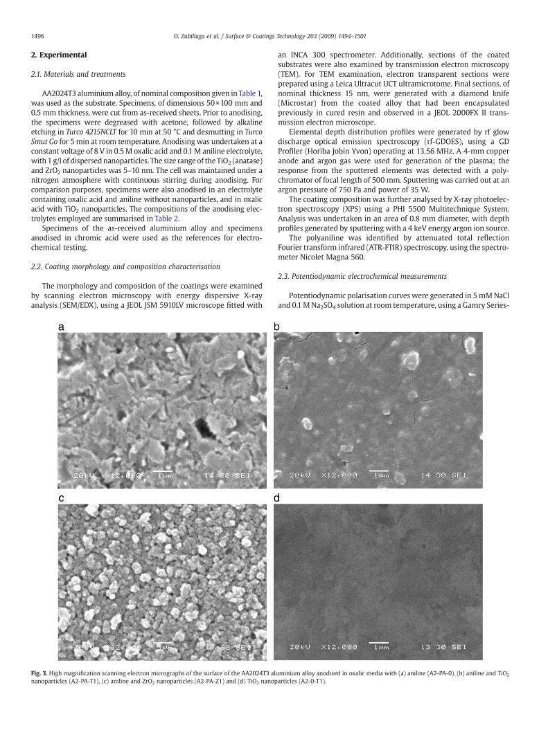
Fig. 2. Scanning electron micrographs of the (a) surface (backscattered electrons) and(b) cross section of the etched and desmutted AA2024T3 aluminium alloy prior toanodising. The number 1 in (a) indicates the copper rich second phase particles. Thenumber 1 in (b) indicates a non covered cavity.
1496 O. Zubillaga et al. / Surface & Coatings Technology 203 (2009) 1494–1501
2. Experimental
2.1. Materials and treatments
AA2024T3 aluminium alloy, of nominal composition given in Table 1,was used as the substrate. Specimens, of dimensions 50×100 mm and0.5 mm thickness, were cut from as-received sheets. Prior to anodising,the specimens were degreased with acetone, followed by alkalineetching in Turco 4215NCLT for 10 min at 50 °C and desmutting in TurcoSmut Go for 5 min at room temperature. Anodising was undertaken at aconstant voltage of 8 V in 0.5M oxalic acid and 0.1M aniline electrolyte,with 1 g/l of dispersednanoparticles. The size range of theTiO2 (anatase)and ZrO2 nanoparticles was 5–10 nm. The cell was maintained under anitrogen atmosphere with continuous stirring during anodising. Forcomparison purposes, specimens were also anodised in an electrolytecontaining oxalic acid and aniline without nanoparticles, and in oxalicacid with TiO2 nanoparticles. The compositions of the anodising elec-trolytes employed are summarised in Table 2.
Specimens of the as-received aluminium alloy and specimensanodised in chromic acid were used as the references for electro-chemical testing.
2.2. Coating morphology and composition characterisation
The morphology and composition of the coatings were examinedby scanning electron microscopy with energy dispersive X-rayanalysis (SEM/EDX), using a JEOL JSM 5910LV microscope fitted with
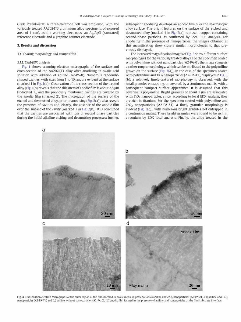
Fig. 3. High magnification scanning electron micrographs of the surface of the AA2024T3 alnanoparticles (A2-PA-T1), (c) aniline and ZrO2 nanoparticles (A2-PA-Z1) and (d) TiO2 nanop
an INCA 300 spectrometer. Additionally, sections of the coatedsubstrates were also examined by transmission electron microscopy(TEM). For TEM examination, electron transparent sections wereprepared using a Leica Ultracut UCT ultramicrotome. Final sections, ofnominal thickness 15 nm, were generated with a diamond knife(Microstar) from the coated alloy that had been encapsulatedpreviously in cured resin and observed in a JEOL 2000FX II trans-mission electron microscope.
Elemental depth distribution profiles were generated by rf glowdischarge optical emission spectroscopy (rf-GDOES), using a GDProfiler (Horiba Jobin Yvon) operating at 13.56 MHz. A 4-mm copperanode and argon gas were used for generation of the plasma; theresponse from the sputtered elements was detected with a poly-chromator of focal length of 500 mm. Sputtering was carried out at anargon pressure of 750 Pa and power of 35 W.
The coating composition was further analysed by X-ray photoelec-tron spectroscopy (XPS) using a PHI 5500 Multitechnique System.Analysis was undertaken in an area of 0.8 mm diameter, with depthprofiles generated by sputtering with a 4 keV energy argon ion source.
The polyaniline was identified by attenuated total reflectionFourier transform infrared (ATR-FTIR) spectroscopy, using the spectro-meter Nicolet Magna 560.
2.3. Potentiodynamic electrochemical measurements
Potentiodynamic polarisation curves were generated in 5mMNaCland 0.1MNa2SO4 solution at room temperature, using a Gamry Series-
uminium alloy anodised in oxalic media with (a) aniline (A2-PA-0), (b) aniline and TiO2
articles (A2-0-T1).
1497O. Zubillaga et al. / Surface & Coatings Technology 203 (2009) 1494–1501
G300 Potentiostat. A three-electrode cell was employed, with thevariously treated AA2024T3 aluminium alloy specimens, of exposedarea of 1 cm2, as the working electrodes, an Ag/AgCl (saturated)reference electrode and a graphite counter electrode.
3. Results and discussion
3.1. Coating morphology and composition
3.1.1. SEM/EDX analysisFig. 1 shows scanning electron micrographs of the surface and
cross-section of the AA2024T3 alloy after anodising in oxalic acidsolution with addition of aniline (A2-PA-0). Numerous randomly-shaped cavities, with sizes from 1 to 10 μm, are evident at the surface(marked 1 in Fig. 1(a)). Observation of the cross-section of the treatedalloy (Fig. 1(b) reveals that the thickness of anodic film is about 2.5 μm(indicated 1), and the previously mentioned cavities are covered bythe anodic film (marked 2). The micrograph of the surface of theetched and desmutted alloy, prior to anodising (Fig. 2(a)), also revealsthe presence of cavities and, clearly, the absence of the anodic filmover the surface of the cavity (marked 1 in Fig. 2(b)). It is concludedthat the cavities are associated with loss of second phase particlesduring the initial alkaline etching and desmutting processes; further,
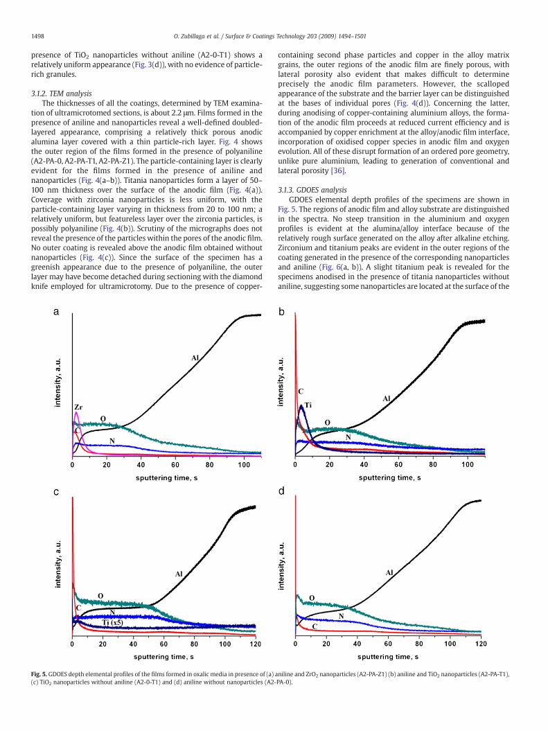
Fig. 4. Transmission electron micrographs of the outer region of the films formed in oxalic mnanoparticles (A2-PA-T1) and (c) aniline without nanoparticles (A2-PA-0); (d) anodic film f
subsequent anodising develops an anodic film over the macroscopicalloy surface. The bright features on the surface of the etched anddesmutted alloy (marked 1 in Fig. 2(a)) represent copper-containingsecond-phase particles, as confirmed by local EDS analysis. Foranodising in the presence of nanoparticles, the images obtained atthis magnification show closely similar morphologies to that pre-viously displayed.
The increasedmagnification images of Fig. 3 show different surfacemorphologies for the variously treated alloys. For the specimen coatedwith polyaniline without nanoparticles (A2-PA-0), the image suggestsa rather rough morphology, which can be attributed to the polyanilinegrown on the surface (Fig. 3(a)). In the case of the specimen coatedwith polyaniline and TiO2 nanoparticles (A2-PA-T1), displayed in Fig. 3(b), a relatively finely-textured morphology is observed, with thesmall granules entrapping, or covered, by a continuous matrix, with aconsequent compact surface appearance. It is assumed that thiscovering is polyaniline. Bright granules of about 1 μm are associatedwith TiO2 nanoparticles, since, according to local EDX analysis, theyare rich in titanium. For the specimen coated with polyaniline andZrO2 nanoparticles (A2-PA-Z1), a finely granular morphology isevident (Fig. 3(c)), with numerous bright granules not entrapped ina continuous matrix. These bright granules were found to be rich inzirconium by EDX local analysis. Finally, the alloy treated in the
edia in presence of (a) aniline and ZrO2 nanoparticles (A2-PA-Z1), (b) aniline and TiO2
ormed in the presence of aniline and nanoparticles at the film/substrate interface.
1498 O. Zubillaga et al. / Surface & Coatings Technology 203 (2009) 1494–1501
presence of TiO2 nanoparticles without aniline (A2-0-T1) shows arelatively uniform appearance (Fig. 3(d)), with no evidence of particle-rich granules.
3.1.2. TEM analysisThe thicknesses of all the coatings, determined by TEM examina-
tion of ultramicrotomed sections, is about 2.2 μm. Films formed in thepresence of aniline and nanoparticles reveal a well-defined doubled-layered appearance, comprising a relatively thick porous anodicalumina layer covered with a thin particle-rich layer. Fig. 4 showsthe outer region of the films formed in the presence of polyaniline(A2-PA-0, A2-PA-T1, A2-PA-Z1). The particle-containing layer is clearlyevident for the films formed in the presence of aniline andnanoparticles (Fig. 4(a–b)). Titania nanoparticles form a layer of 50–100 nm thickness over the surface of the anodic film (Fig. 4(a)).Coverage with zirconia nanoparticles is less uniform, with theparticle-containing layer varying in thickness from 20 to 100 nm; arelatively uniform, but featureless layer over the zirconia particles, ispossibly polyaniline (Fig. 4(b)). Scrutiny of the micrographs does notreveal the presence of the particles within the pores of the anodic film.No outer coating is revealed above the anodic film obtained withoutnanoparticles (Fig. 4(c)). Since the surface of the specimen has agreenish appearance due to the presence of polyaniline, the outerlayer may have become detached during sectioning with the diamondknife employed for ultramicrotomy. Due to the presence of copper-
Fig. 5. GDOES depth elemental profiles of the films formed in oxalic media in presence of (a) a(c) TiO2 nanoparticles without aniline (A2-0-T1) and (d) aniline without nanoparticles (A2-
containing second phase particles and copper in the alloy matrixgrains, the outer regions of the anodic film are finely porous, withlateral porosity also evident that makes difficult to determineprecisely the anodic film parameters. However, the scallopedappearance of the substrate and the barrier layer can be distinguishedat the bases of individual pores (Fig. 4(d)). Concerning the latter,during anodising of copper-containing aluminium alloys, the forma-tion of the anodic film proceeds at reduced current efficiency and isaccompanied by copper enrichment at the alloy/anodic film interface,incorporation of oxidised copper species in anodic film and oxygenevolution. All of these disrupt formation of an ordered pore geometry,unlike pure aluminium, leading to generation of conventional andlateral porosity [36].
3.1.3. GDOES analysisGDOES elemental depth profiles of the specimens are shown in
Fig. 5. The regions of anodic film and alloy substrate are distinguishedin the spectra. No steep transition in the aluminium and oxygenprofiles is evident at the alumina/alloy interface because of therelatively rough surface generated on the alloy after alkaline etching.Zirconium and titanium peaks are evident in the outer regions of thecoating generated in the presence of the corresponding nanoparticlesand aniline (Fig. 6(a, b)). A slight titanium peak is revealed for thespecimens anodised in the presence of titania nanoparticles withoutaniline, suggesting some nanoparticles are located at the surface of the
niline and ZrO2 nanoparticles (A2-PA-Z1) (b) aniline and TiO2 nanoparticles (A2-PA-T1),PA-0).

Fig. 6. XPS depth profiles of the nanoparticle-rich outer layer and adjacent anodised layer recorded for the AA2024T3 alloy anodised in oxalic media with (a) aniline and TiO2
nanoparticles (A2-PA-T1), (b) aniline and ZrO2 nanoparticles (A2-PA-Z1) and (c) TiO2 nanoparticles (A2-0-T1).
Fig. 7. ATR-FTIR spectrum of the A2-PA-0 film.
1499O. Zubillaga et al. / Surface & Coatings Technology 203 (2009) 1494–1501
1500 O. Zubillaga et al. / Surface & Coatings Technology 203 (2009) 1494–1501
porous anodic film (Fig. 6(c)). It is difficult to confirm the presence ofpolyaniline in the anodic film by GDOES from the carbon or nitrogenelemental depth profiles. Concerning carbon, oxalate (and associatedcarbon) species are incorporated in the anodic film formed in oxalicacid during anodising; further, the high carbon content in the outercoating region may be associated with contamination during storageof the specimens. The increased intensity of nitrogen in the anodicfilm region compared with that in the alloy region may result fromdifferent sputtering rates rather the presence of nitrogen species inthe coating. Similar behaviour for nitrogen has been observed forbarrier anodic alumina films on aluminium, where no source ofnitrogen was available during film formation. However, the presenceof polyaniline on the surface of the specimens anodised with aniline,with andwithout nanoparticles, is certainly confirmed by the greenishsurface appearance. The greenish appearance disappears afterremoval of particle-rich regions in the specimens with titania andzirconia nanoparticles, suggesting again that polyaniline is mostlylocated in the outer region of the coating.
3.1.4. XPS analysisThe XPS depth profiles show peaks in the titanium or zirconium
profiles for the appropriate specimens at the commencement ofsputtering, confirming the presence of a nanoparticle-rich layer in thenear-surface regions of the anodic films. The elemental titaniumpercentage at the outer surface is about 30% (Fig. 6(a)), whichdecreases gradually to its background level over a thickness ofapproximately 250–300 nm. In the case of the ZrO2-nanoparticlecontaining coating (Fig. 6(b)), the elemental zirconium percentage atthe outer surface is also about 30%, decreasing gradually over athickness of 200–250 nm. In the case of the film with titaniananoparticles and without polyaniline, titanium was detected at acontent below 1% over the outer 20 nm of analysis (Fig. 6(c)).
3.1.5. ATR-FTIR analysisThe ATR-FTIR spectrum of the A2-PA-0 film is shows in Fig. 7. The
peaks at 1715 cm−1, 1688 cm−1, 1415 cm−1 and 1287 cm−1 are assignedto vibrations of the adsorbed oxalate species [37–40]. The stretchingvibration modes of the benzenoid and quinoid ring of the polyanilineare observed in the spectrum at 1497 cm−1 and 1602 cm−1
respectively [41–44]. The third peak assigned to the polyaniline is
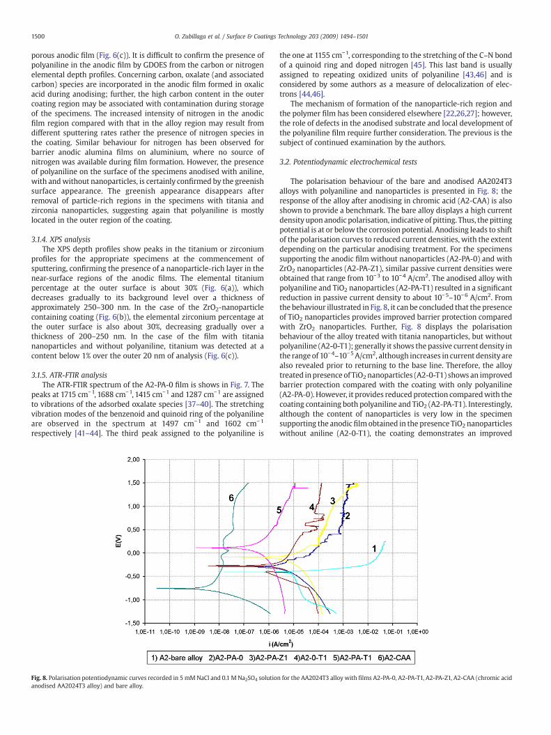
Fig. 8. Polarisation potentiodynamic curves recorded in 5 mMNaCl and 0.1 M Na2SO4 solutioanodised AA2024T3 alloy) and bare alloy.
the one at 1155 cm−1, corresponding to the stretching of the C–N bondof a quinoid ring and doped nitrogen [45]. This last band is usuallyassigned to repeating oxidized units of polyaniline [43,46] and isconsidered by some authors as a measure of delocalization of elec-trons [44,46].
The mechanism of formation of the nanoparticle-rich region andthe polymer film has been considered elsewhere [22,26,27]; however,the role of defects in the anodised substrate and local development ofthe polyaniline film require further consideration. The previous is thesubject of continued examination by the authors.
3.2. Potentiodynamic electrochemical tests
The polarisation behaviour of the bare and anodised AA2024T3alloys with polyaniline and nanoparticles is presented in Fig. 8; theresponse of the alloy after anodising in chromic acid (A2-CAA) is alsoshown to provide a benchmark. The bare alloy displays a high currentdensity upon anodic polarisation, indicative of pitting. Thus, the pittingpotential is at or below the corrosion potential. Anodising leads to shiftof the polarisation curves to reduced current densities, with the extentdepending on the particular anodising treatment. For the specimenssupporting the anodic film without nanoparticles (A2-PA-0) and withZrO2 nanoparticles (A2-PA-Z1), similar passive current densities wereobtained that range from 10−3 to 10−4 A/cm2. The anodised alloy withpolyaniline and TiO2 nanoparticles (A2-PA-T1) resulted in a significantreduction in passive current density to about 10−5–10−6 A/cm2. Fromthe behaviour illustrated in Fig. 8, it can be concluded that the presenceof TiO2 nanoparticles provides improved barrier protection comparedwith ZrO2 nanoparticles. Further, Fig. 8 displays the polarisationbehaviour of the alloy treated with titania nanoparticles, but withoutpolyaniline (A2-0-T1); generally it shows the passive current density inthe rangeof 10−4–10−5 A/cm2, although increases in current densityarealso revealed prior to returning to the base line. Therefore, the alloytreated inpresence of TiO2 nanoparticles (A2-0-T1) shows an improvedbarrier protection compared with the coating with only polyaniline(A2-PA-0). However, it provides reduced protection comparedwith thecoating containing both polyaniline and TiO2 (A2-PA-T1). Interestingly,although the content of nanoparticles is very low in the specimensupporting the anodicfilm obtained in the presence TiO2 nanoparticleswithout aniline (A2-0-T1), the coating demonstrates an improved
n for the AA2024T3 alloy with films A2-PA-0, A2-PA-T1, A2-PA-Z1, A2-CAA (chromic acid
1501O. Zubillaga et al. / Surface & Coatings Technology 203 (2009) 1494–1501
polarisation behaviour in comparedwith that obtained in the presenceof aniline.
The improved performance offered by the polyaniline and TiO2
nanoparticle containing coatings is attributed to the presence of thenanoparticle-rich layer in the near-surface region, which acts as abarrier layer that blocks access to the pores of the anodic alumina film.The effect of blocking pores by TiO2 nanoparticles is further enhancedwhen nanoparticles and polyaniline are combined. The filmwith ZrO2
nanoparticles shows no additional barrier effect in contrast with thosewith TiO2 nanoparticles, resulting in increased passive currentdensities, and demonstrating no significant improvement. For thespecimens anodised in the presence of aniline and nanoparticles, anincrease in corrosion potential is evident compared with the barealloy. This confronts with the behaviour of the alloy after anodisingin chromic acid, where a reduced corrosion potential is displayed. Onthe basis that the anodising treatment acts to limit the anodic sites onthe alloy surface, an additional effect of anodising in chromic acid isthe significant reduction in the cathodic kinetics limiting further thedriving force for corrosion.
4. Conclusions
Anodic alumina films containing polyaniline and TiO2 or ZrO2
nanoparticles were electrochemically synthesised on an AA2024T3aluminium alloy in oxalic acid electrolyte containing dissolved anilineand dispersed nanoparticles. The resultant coatings, with a thicknessof about 2.2 μm, comprise an anodic inner film and an outerpolyaniline and nanoparticle rich, with a thickness in the range of100–250 nm. Anodising with TiO2 nanoparticles and without polyani-line results in incorporation of a significantly reduced amount ofnanoparticles.
The potentiodynamic polarisation testing revealed that the coat-ings with polyaniline and TiO2 nanoparticles provide the bestprotection to the AA2024T3 aluminium alloy, revealing a passivecurrent density two orders of magnitude lower than the films withZrO2 nanoparticles and without nanoparticles. The coatings with TiO2
nanoparticles, but without polyaniline, demonstrate intermediatebehaviour, with a passive current density one order of magnitudehigher than the coatings with polyaniline and TiO2 nanoparticles. Theimproved corrosion protection offered by the anodic coating contain-ing TiO2 nanoparticles is attributed to the presence of the nanopar-ticle-rich layer formed at the outer surface of the anodic coating,which blocks the pores of the anodic alumina film providing improvedbarrier properties.
Acknowledgements
Authors acknowledge the European Commission for the fundingto carry out this work under the project MULTIPROTECT (ContractNo. NMP3-CT-2005-011783).
References
[1] J.R. Davis, Corrosion of Aluminum and Aluminum Alloys, First editionASMInternational, USA, 1999.
[2] C. Blanc, B. Lavella, G. Mankowski, Corros. Sci. 39 (3) (1997) 495.[3] V. Guillaumin, G. Mankowski, Corros. Sci. 41 (1999) 421.[4] P. Campestrini, H. Terryn, J. Vereecken, J.H.W. de Wit, J. Electrochem. Soc. 151 (6)
(2004) B359.[5] P. Campestrini, H. Terryn, J. Vereecken, J.H.W. de Wit, J. Electrochem. Soc. 151 (6)
(2004) B370.[6] M. Kendig, S. Jeanjaquet, R. Addison, J. Waldrop, Surf. Coat. Technol. 140 (2001) 58.[7] A.W. Brace, The technology of anodising aluminium, Third editionInterall S.r.l.,
Italy, 2000.[8] V.P. Parkhutik, Corros. Sci. 26 (4) (1986) 295.[9] H. Habazaki, K. Shimizu, P. Skeldon, G.E. Thompson, G.C.Wood, X. Zhou, Corros. Sci.
39 (4) (1997) 731.[10] M.A. Páez, T.M. Foong, C.T. Ni, G.E. Thompson, K. Shimizu, H. Habazaki, P. Skeldon,
G.C. Wood, Corros. Sci. 38 (1) (1996) 59.[11] A. Bautista, J.A. González, V. López, Surf. Coat. Technol. 154 (2002) 49.[12] V. Moutarlier, M.P. Gigandet, J. Pagetti, B. Normand, Surf. Coat. Technol. 182 (2004)
117.[13] F. Snogan, C. Blanc, G. Mankowski, N. Pébére, Surf. Coat. Technol. 154 (2002) 94.[14] M.J. Bartolomé, V. López, E. Escudero, G. Caruana, J.A. González, Surf. Coat. Technol.
200 (2006) 4530.[15] G.E. Thompson, R.C. Furneaux, G.C. Wood, Trans. Inst. Met. Finish. 53 (1995) 97.[16] Y. Zuo, P.H. Zhao, J.M. Zaho, Surf. Coat. Technol. 166 (2003) 237.[17] V. Moutalier, M.P. Gigandet, L. Ricq, J. Pagetti, Appl. Surf. Sci. 183 (2001) 1.[18] V. Moutalier, M.P. Gigandet, L. Ricq, J. Pagetti, Appl. Surf. Sci. 206 (2003) 237.[19] V. Moutalier, M.P. Gigandet, J. Pagetti, B. Normand, Surf. Coat. Technol. 161 (2002)
267.[20] V. Moutalier, M.P. Gigandet, J. Pagetti, L. Ricq, Surf. Coat. Technol. 173 (2003) 87.[21] X. Yu, C. Cao, Thin Solid Films 423 (2003) 252.[22] K. Kamada, M. Tokutomi, N. Enomoto, J. Hojo, J. Mater. Chem. 15 (2005) 3388.[23] K. Kamada, H. Fukuda, K. Maehara, Y. Yoshida, M. Nakai, S. Hasuo, Y. Matsumoto,
Electrochem. Solid-State Lett. 7 (2004) B24.[24] F. Beck, P. Hülser, J. Electroanal. Chem. 280 (1990) 159.[25] D. Huerta-Vilca, S. Regina de Moraes, A. de Jesus Motheo, Synth. Met. 140 (2004)
23.[26] K. Naoi, M. Takeda, H. Kanno, M. Sakakura, A. Shimada, Electrochim. Acta 45 (2000)
3413.[27] M.L. Tsai, P.J. Chen, J.S. Do, J. Power Sources 133 (2004) 302.[28] R. Gangopadhyay, A. De, Chem. Mater. 12 (2000) 608.[29] D.C. Schnitzler, A.J.G. Zarbin, J. Braz. Chem. Soc. 15 (2004) 378.[30] S. Sinha Ray, M. Biswas, Synth. Met. 108 (2000) 231.[31] K. Gurunathan, D.C. Trivedi, Mater. Lett. 45 (2000) 262.[32] A. Bhattacharya, K.M. Ganguly, A. De, S. Sarkar, Mater. Res. Bull. 31 (5) (1996) 527.[33] D.M. Lenz, C.A. Ferreira, M. Delamar, Synth. Met. 126 (2002) 179.[34] Y. Liu, J. Huang, C. Tsai, T.C. Chuang, C. Wang, Chem. Phys. Lett. 387 (2004) 155.[35] Y. Zhu, J.O. Iroh, J. Adv. Mater. 34 (4) (2002) 16.[36] L. Iglesias-Rubiane, S.J. Garcia-Vergara, P. Skeldon, G.E. Thompson, J. Ferguson, M.
Beneke, Electrochim. Acta 52 (2007) 7148.[37] S.J. Hug, D. Bahnemann, J. Electrón Spectrosc. Relat. Phenom. 150 (2006) 208.[38] K.D. Dobson, A.J. McQuillan, Spectrochim. Acta, Part A 55 (1999) 1395.[39] C.B. Mendive, D.W. Bahnemann, M.A. Blesa, Catal. Today 101 (2005) 237.[40] P.A. Araujo, C.B. Mendive, et al., Colloids Surf., A Physicochem. Eng. Asp. 265 (2005)
73.[41] I. Sedenková, J. Prokes, M. Trchová, J. Stejskal, Polym. Degrad. Stab. 93 (2008) 428.[42] H. Okamoto, T. Kotaka, Polymer 39 (18) (1998) 4349.[43] R. Singh, V. Arora, R.P. Tandon, S. Chandra, N. Kumar, A. Mansingh, Polymer 38 (19)
(1997) 4897.[44] L. Li, G. Yan, J. Wu, X. Yu, Q. Guo, J. Colloid Interface Science 326 (2008) 72.[45] X. Li, D. Wang, et al., Appl. Catal. B, Environ. 81 (2008) 267.[46] H. Zengin, W. Zhou, J. Jin, R. Czerw, D.W. Smith, L. Echegoyen, D.L. Carroll, S.H.
Foulger, J. Ballato, Adv. Mater. 14 (2002) 1480.
![Nanoparticles on the Characteristics of MAO Coatings · MAO, known as anodic spark deposition (ASD) [1] and plasma electrolytic oxidation (PEO) [2], or micro-arc discharge oxidation](https://img.pdfslide.net/doc/110x75/602aebdcfe7fe7035a1882f4/nanoparticles-on-the-characteristics-of-mao-mao-known-as-anodic-spark-deposition.jpg)