Embed Size (px)
Citation preview
HAL Id: tel-00782086https://tel.archives-ouvertes.fr/tel-00782086
Submitted on 29 Jan 2013
HAL is a multi-disciplinary open accessarchive for the deposit and dissemination of sci-entific research documents, whether they are pub-lished or not. The documents may come fromteaching and research institutions in France orabroad, or from public or private research centers.
L’archive ouverte pluridisciplinaire HAL, estdestinée au dépôt et à la diffusion de documentsscientifiques de niveau recherche, publiés ou non,émanant des établissements d’enseignement et derecherche français ou étrangers, des laboratoirespublics ou privés.
Anomalies in relief diffraction gratingsEvgeni Popov
To cite this version:Evgeni Popov. Anomalies in relief diffraction gratings. Optics [physics.optics]. Academie des Sciencesde Bulgarie, 1991. English. <tel-00782086>
INSTITUTE DE PHYSIQUE DES SOLIDES ACADEMIE DES SCIENCES DE BULGARIE
THESE
Pour obtenir le grade de DOCTEUR ès Sciences
délivré par l’Academie des Sciences de Bulgarie
Discipline : Physique de la matière condensée et du rayonnement
présentée et soutenue publiquement par Evgeny POPOV
le 14 Avril 1991 Le directeur et co-directeur de thèse : autodirection Laboratoire d'accueil: Institut de Physique des Solides Membres du jury: I. Lalov P. Simova E. Atanasova E. Leyarovski V. Georgiev
1991
INSTITUTE OF SOLID STATE PHYSICS BULGARIAN ACADEMY OF SCIENCES
EVGENY KONSTANTINOV POPOV
ANOMALIES IN RELIEF DIFFRACTION GRATINGS
SUMMARY of a thesis for awarding a Doctor of Sciences degree
Sofia, 1990
Printed by the Union of the Scientist of Bulgaria, Blvd. Lenin 73, Sofia, Bulgaria,
1990
INTRODUCTION
Devoted ta the memory of
my friend and teacher
Lyuben Mashev
Contrary ta common sense, scientist is usually thrilled with the
ward 'anomal y'. This paradox could easlly be explained - anomaly meana
something abnormal, unexpected, i.e. unpredicted, novel. Wh en R. Wood
in 1902 observed sorne unexpected property of diffraction gratings
diffraction efficiency changes more than 10 times in the spectral
region not ltu·ger than the distance between sodium !ines, he called
thaf"' phenomenon 'anomalous', This term proves ta be sa fascina ting
th~t even when sorne anomalies find their explanation (becorne 'normal'
from a theoretical point of view) phenomena they represent continue to
be called anomalous,
Explained or not, each more or lesa rapid change in diffraction
efficicncy of gratings is called anomaly. Great interest in almost
century lasting investigation of anomalies could find its explanation
in the following ressons:
1. Their ·appearance is connected with sorne physical phenomena that
attract attention by themselves.
2. Hany of the anomafies are connected with surface wave excitation
and could provide information for their properties.
3. For the most of grating applications it is more important to have
smooth, rather than very high diffraction efficiency - anomalies must
be avoided,
4. It appears that in some casee very high efficiency values could be
anomalous-, too, Detailed investigations of anomalies could reSult in
sorne interesting applications,
5, Theory of anomalies provides incomparable stimuli
of recent numerical methode for analysis of light
nlief gratings.
for development
diffraction by
The necessity ,f the thesis is due mainlr to the lack of
detailed investigation of 1!.ll anomalies. In the last years new
anomalies have been discovered that make it possible to develop a new
uriited classification of anomalies and to determine the connections
that exist between them, The Aimft of the investigation when working on
- 2 -
the the sis were:
1. Developing program packages based on the recently published or
original rigorous methods for analysis of light diffraction by relief
gratings, verification of the computer codes and determination of
their efficiency and regions of applic8tion.
2, Theoretical and experimental investigation of some anomalies in
different' types of gratings {metnllic 1 dielectric and multilayered)
and of the possibility of utilizing anomalous properties;
3. Determination_of physical connections between different anomalies
and ressons for their appearance. This was done on two levSls:
a) phenomenological i t ena bled to draw connections between
an?malies:
b) microscopical- what are the properties of electromagnetic'field in
the nenr zone of diffrnction and how its pecu1iB:rities infiuènce the
far-field diffraction efficiency,
The thesis consista of 10 chapters divided in -threè~,,parts; 'The
first IUU:.t. contains three chapters, It deals~with the ~.~ten&'rè:l/"features of light diffraction by relief gratings (statement -Or>,the.:·:problem,
sorne main theorems), histories! review of investigatioris:.:!Jn anomalies
and the ir recent classification. Chapter three contains. a review of
the theoretical methods, including a detailed presentation of the used
in our laboratory rigorous numerica.l method.
Part iHQ presents anomalies in bare metallic gratlngs
resonance ( chspter 5) and non-resonance ( chnpter 4 and 6) à nd some
exsmples o~ their interaction (chspter 7}. It is shawn how sorne
general properties of metallic gratings could be explained from a
microscopical point of view.
analyzes anomalies . in corrugated diel·ectric
wsveguides - whst is the influence of waveguide mode excitation on the
diffraction efficiency without (chapter 8) and with (chapter 10) mode
interactions. -Anomaly in the coefficients of mode coupling (planar
Brewster' s effect} is studied in chapter 10. Non-resonance anomalies
in bsre dielectric gratings 6re discusses in chapter 9.
- 3 - i
PART ONE, UGHT DIFTRACTION BY I?ElJEF GI?ATINGS
CHAPTER ONE: BASIC PROPERTIES OF DIFFRACTION ORATINGS
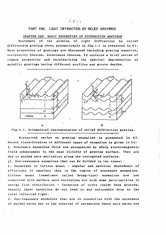
Statement of the problem of light diffraction by relief
diffraction grating shawn schematically in fig,l.l is presented in §1,
Main properties of gratings are discussed including grating equation,
reciprocity theorem, invariance theorem. §2 containa a brief review of
cornmon properties and peculiarities the spectral dependenèies of
metallic gratings having different profiles and groove depths,
• b
Fig.l.l. Schematical representation of relief diffraction gratins.
Historical review on grating anomalies is presented in §3,
Recent classification of different types of anomalies is given in §4:
I· Resonance anomalies which are accompanied by sharp electromagnetic
field enhancement in the near vicinity of grating surface. They are
due to guided wave excitation along the corrugated surfaces.
Il_, Non-resonance anomalies that can be divided in two types:
1. Anomalies in Littrow mount - sngular and spectral dependence of
efficiency is smoother than in the region of resonance anomalies.
Littrow mount {sometimes called Bragg-type) anomalies are not
connected with surface wave excitation but with sorne peculiarities in
energy flow distribution - formation of curls inside deep grooves.
Usually t.hese anomalies do not lead to any noticeable drop in the
total reflected light.
2. Non-resonance anomalies that are in connection with the existence
of guided waves but in the intervnl of parameters where such waves are
- 4 -
forbidden {chapter 5 and 6).
Of course with a suitable choice of conditions it is possible to
have a simultaneous appearance of two or more anomalies, their
interaction and even 'annihilation'.
It is important to note that one and the same phenomenon could
result in different anomalies in different diffraction orders, That is·
why anomalies in the Oth and -lst orders are considered separately in
the corresponding chapters.
CBAPTER TWO: SURFACE WAVES AND RESONANCE ANOMALIES
This chapter explains the mechsnism by which surface wave
·excitation leads to anomalies in the diffraction efficiency, For this
sim a brief review la presented of surface waves that propagate along
plane metal-dielectric boundary and in p1Ul ti laye red pl anar waveguides,
§ 2 co'ntains the so cal led phenomenological approach that representa
surface wave excitation. in corrUgated system by a set of zeros a-z and
pol es aP of the scattering matrix S ( 19 1 20], Its components could be
represented in the resonance anomaly region by the phenomenological
formula:
where a 0 is
and there
the
a 0
a 0
sinus of angle
(2. 1)
of incidence. Without corrugation a~saP
are no anomalies. Existence of grating leads to the
splitting of pole and zeros. Tracing of their trajectOries in the
complex a0
plane as a fonction of groove depth and/or wavelength is a
strong tool for investigation of anomaly connectiQns and oriSin.
When incident wave vector is not perpendicular to the grooves
(conical diffraction mounting), representation (2.1) becomes more
complicated, Using reciprocity theorem it is shown how arbitrary
polarized incident wave can be decomposed into two mU:tually orthogonal
components (in general, elliptically polarized), One Of them (with
amplitude p1 ) is not interacting with the surface !'J:llVe. Thus in the
phenomenological formulae · (2.1) a new slowly varying term is added,
prOpori.iorlal to p1
·,
'i 3 discusses the two main features of mode interaction: 1) i ts
influence on th.e resonance anomalies and how it can be reflected in
the phenomenological formulae; 2) ~nergy transfer between interacting.
œodes 1 variation of their amplitudes in the corrugated region a~d mode
- 5 -
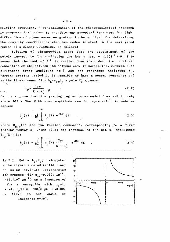
coupling equations. A generalization of the phenomenological approach
is proposed thllt makes it possible any numerical treatment for light
diffraction of plane waves on grating to be utilized for determining
the coupling coefficients· when two modes internet in the corrugated
region of a planar waveguide, as follows:
Solution of eigenproblem means that the determinant of the
rnatrix inverse to the scattering one has a zero - det(S- 1 )=O. This
means that the rank of S- 1 is smaller than its arder, i.e. a linear
connection exista between its columns and, in particular, between j-th
diffracted arder amplitude (b,_,) and the resonance amplJtude h11
.
Varying grating period i t is possible to have a second resonance and
in the linear connect!on bv:::cV/lbp a pole K~ appears:
b==~b v K - KP Il
v Let us suppose that the gratins reg ion is
where L»d. The Jl- th mode ampli tude can
series: ro
bp(X) = J_l BJlf K) eiKx dK
are where Bp,v(K)
grating vector K.
the Fourier components
Using (2.2) the response
is:
'ig.2,1. Ratio b1
/b0
, calculated
y the rigorous metod {solid line)
nd using eq,(2.2) (represented
ith crosses with c01
=0.0201 Pm- 1,
'=41.7107 pm- 1) as a function of
for a wavegu ide
=2.3, n3
=1.6, t=o:3
.\=0.6 pm and
with n1
=1,
prn, h=0.004
angle of
incidence v=30°.
" • u
•uo1
·• ·• ·•
( 2. 2)
extended from x==O ta x=L,
Fourier be represented in
(2, 3)
corresponding ta a fixed
to the set of amplitudes
'"" on • UJIJ
- 6 -
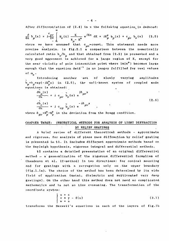
After differentia. tian of {2.-4) in x the folloWing equation, is deduced:
~ b (x) = i~ lB (K) _K __ x Il rr v K - KP
- " (2.5)
where we have nssumed that
precise ~nalysis, In fig.Z.l
cpv~const, This statement needs more
a comparison between the numericnlly
calculated ratio bv/b11
and thnt obtained from (2.2) is presented and a
very good agreement is achieved for a large region of K1 except for
the near vicinity of pole interaction point where Im(aP) becomes large
enough that the equation detS-l is no longer fulfilled for real values
of <10
•
lntroducing nnother
h11 =h11 exp{-iK~x) in (2.5),
eqttations is obtained:
db11
(x)
--ax- = i c bv(x)
"" db J>(x}
--ax- c
"" \J(x)
of slowly varying amplitudes
th• well-known system of coupled mode
e iBIJVX
( 2. 6) - iS pvx
e
\.'he re ô"" =KP -KP is the deviation from the Bragg condition,
" v
CHAPTER THREE: THEORETICAL HETHODS FOR ANALYSIS OF LlG!lT DIFFRACTION
BY RELIEF ORATINGS
A brief review of different theoretice.l methods approxime. te
a.nd rigorous 1 for analysis of plane ~ave diffrac.tion by relief grating
is presented in ~1. It includes diffe~ent approximate roethods based on
the Rayleigh hypothesis, rigorous integral and differentiai methods,
§2 contains a detailed presentation of an original differentia!
method - a· generalization of the rigorous differentia! form~l-ism of
Chandezon et al, (C-method) in two directions: for conical mounting
and for gratings with a corrugation only on the upper boundary
(fig.l,1a). The choice of the method has been determined by its wide
field of application (metal, dielectric and multicoa.ted very deep
gralings), On the other hand this method does not need so complicated
mathemstics and is not so time consuming. The transformation of the
coordinate system:
x y
= z f(x) 1 3.1)
transforma the Maxwell' s equations in each of the layera of fig.lb
- 7 -
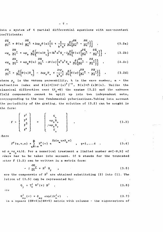
into a system of 4 p.artial differentiai equations with non-constant
coefficients:
:i-)} :i-]}
iwp a [ ("" 811 ]] + k;ln~ iJulc { u) td - ru
(3.2a}
(3.2b)
(3.2c)
(3.2d)
where J-10
is the vacuum permeablli ty, k is the wave number, n - the
refra.ctive index and C(x):::{l+f·(x) 2 r 1 D(x)=f·(x)C(x}. Unlike the
classical diffraction case (IJ0
=:0) the system (3.2.) nnd the unknown
field components cannat be split up into two independent sets,
corresponding ta the two fundamental polarizations.Taking into account
the periodici ty of the grating, the solution of ( 3. 2} ca.n be sought in
the form:
F [ ~ l [
E,
li>p H 0 "
,-w11 H 0 •
E " l
ik(u u+/3 w} • • 0
{ 3. 3)
p=l' ••• 4 (3 .4)
nd a =a +À/d, for a numerical trentment a limited number m~[-N,NJ of • 0
rders ha.s to be taken into account. If G stands for the trunca.ted
~ctar F (3.2) can be written in a matrix form:
. dGJ - 1 ('{V' :::: RJ GJ { 3. 5)
ere the components of RJ are obtained subatituting (2) inta (1). The
lution of (3.5) can be represented by:
( 3. 6)
~re
,l>J (v)= 5 exp(ir~v) (3.7) mp n>p ~·
is a square {8Nt4)x(8N+4} matrix with columns - the eigenvectors of
- 8 -
RJ. rJ are the corresponding eigenvalues and BJ conta.ins the unknown
~mplitudes determined by the boundary and outgoing wave conditions, In
the Ouvw coordinate system the boundaries between the layera are
dafined by v=1J and a connection.between the unknown amplitudes at the
two aides of the J-th boundary is quite simple:
TJ olJJ ( 1 ) BJ = TJ + 1 'l'J + 1 { 1 ) BJ + 1 • ( 3. B} c j c J
Using (3.8) a connection between the amplitudes in the upper and lower
Jlledia can be fou nd, Taking into account the outgoing wave candi ti ons
the system (3,2) is reduced to a more simple linear algebraic system.
The description of 'the system shawn schematically in fig .l.la
needs a complication of field representation in the second region. For
'y<min{f(x)] the field cAn be expanded in plane waves:
av ;J(r)BJ J
ik/J0
z e (3. 9)
where 0 =ô exp( ia x) and "'l' m-p m
;J (y)=ô exp(itJy), x 2 =n3 -a1 . The
uniqueness of the solution in . mp mp .. m ..
1 m
the second region connecta F l y=12
and
B2• The boundary conditions at the flat boundaries y= 1
1, , •• 1..,_
1 make
it possible to express the diffracted waves amplitudes via the
incident ones,
It has been pointed out that the most important criterion of the
quality of a numerical method is its efficiency - ability to deal with
a wide class of gratings in a relatively short computation time 1
rather than its simplicity. It is well known that the computation time
in the matrix operations is proportional to the cube of the matrix
size, so the most important factor becomes the convergence rate with
respect to the truncation pnrameter N. We have made a set of
calculations in arder to perform the limita of method applications for
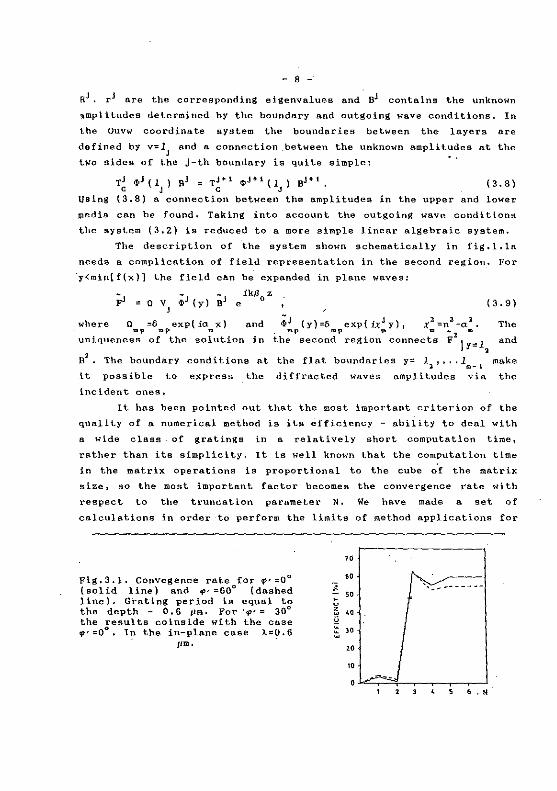
Fig,3.1. Convegence rate for ~·=0° (solid line) and ~- =60° (dnshed line). Grating period is equal to the depth - 0,6 pm. For ''l''= 30° the resulta coinside with the case ~·=0°, In the in-plane case k=O.S
"m,
" "
" "
('v ______ _
---- .H
- 9 -
different types of gro.tings. It happens the.t the saturation value is
obta.ined at one and the same N independant of the angle 'P.' between the
incident wuve vector and the plane perpendicular to the grooves
corresponding to the deviation from the classical diffraction case. As
an example in fig,3.1 the -lst diffraction order efficiency of a bare
sinusoida.l Al grating is shown for three different values of <P': 00 '
30° and 60° far a TH polarized incident light; the convergence is one
and the same for the three cases. That is why in the next examples
only the cl!'tssics.l diffraction case is investigated and the
conclusions are valid for the Chandezon's formulation, too. A
comparison ha.s been made with the well- known Rayle-igh-Fourier (RF)
non-rigoraus method and far metal, dielectric and coated grntings the
foli'owing general conclusions can be drawn:
~·,The results of Wlrgin [67, 6S) conccrning the validity of the RF
nethod for sinusoidnl gratings with depth far exceeding the
.heoretica.l limit are confirmed. On the other hnnd the rigorous nwthod
bath in the conical a.nd classical cases) hns a fe.ster convergence
hich diminishes much alower than that of the RF method - for gratings
r moderate and high depth values (h/d>0.2) the computer time gain
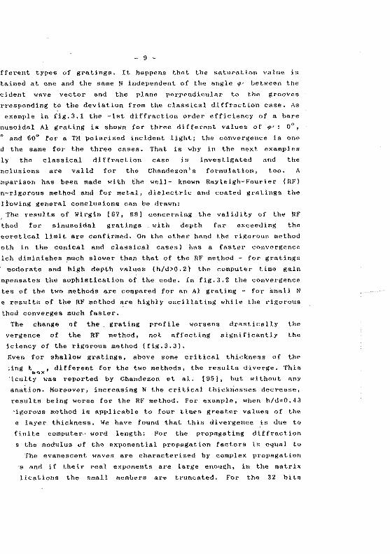
1mpensates the sophistication of the code. In fig.3.2 the convergence
tes of the two methods ar~ compared for an Al gruting - for Srnall N
e results of the RF method are highly oscillating while the rigorous
thod converges much fastcr.
The change of the grating profile worsens drastically the
vergence of the RF method, not affecting significantly the
iciency of the rigoroos methcd (fig.3.3).
Even for shallow grntings, above sorne critical thicl·mes.s of the
·,ing t , different for the two methods, the results diverge. This ... "iculty wa.s reported by Chs.ndezon et al, [95}, but without anY
anatian. Horeover, increa.sing N the critical thickriesses decrense,
results being worse for the RF method. For example, when h/d=0.43
·igorous method is applica.ble to four times greater V8.lues of the
e layer thickness. We ha.ve found that this divergence is due to
fini te computer.• word length: For the propagllting diffraction
s the modulus of the exponential propagation factors is eqUlll to
The evanescent •rHwes are che.rncterized by complex propagation
s and if their real exponents are large enough, in the rnatrix
lications the small members are trunca.ted. for the 32 bits
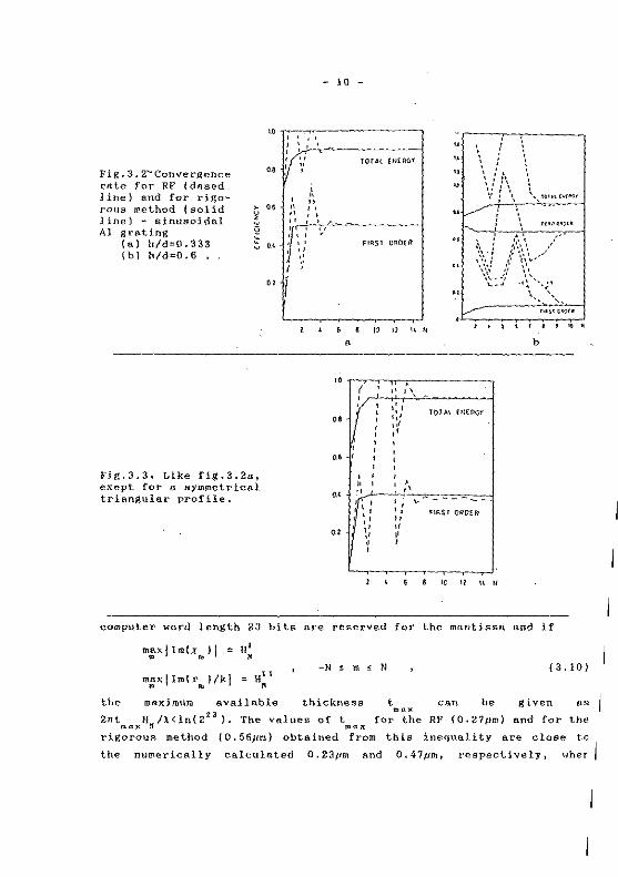
Fig.3.2~Convergence
rate for RF (dased line) and for rigarous method (solid line) - sinusoidal Al grating
(a} h/d"'D.333 (bi h/d=0.6 •
Fig.3.3, Like fig.3.2a 1
exept for a symmetrical triangulnr profile.
- 10 -
" li i-!\ :'--'' .. ~------1 c~ i, ~·
TOTAl E/!fl\C,T_
" " " " lir ' '' "' Il :.i
J '
"
' " " '' ', "
,,
" .. '·' ,,
FIIIST OI!OtR
' ! ,, '\ -(! 1:r
'•' "' ' •'
' ' ., •'
:r:' ' 1 ' '• :· " •' " •' ,, ,, ' '
" ' ' " " ': " ' " ~: \
' ', ·~"' !•1"'' .. ./" ..
..
\ JH~~·~u
1 .~. ', ,-
,•, ' .~ .. ~.\\ __ / '·.·:· ... ·,: .... ~~ .... \·~- -~,' ', '-
'- _.. -·~ ··-.;• \. ',,_
J • \ 1 ' 1 ..
b
.
TOI AL Hl(ll(;r
"liST ()ROU~
" " " u
computer word length 23 bits are reserved for the mantisse. and if
m:xJim(xmll = ll~
m:xl!mfr"')/kj "'H~ 1 -N s m ~ N ( 3. 101
the maximum a.vailable thickness t can be given as .... 2nt H /).<ln(223
), The values of t for the RF (0.27pm) and for the ,.a,.: If "'"'x
rigorous method {0.56pm} obte.ined from this inequnlity are close to
the numerically ca.lculnted 0.23tJm alld 0,47prn, respectively, wher
- 11 -
h/d=0.34 1 for example.
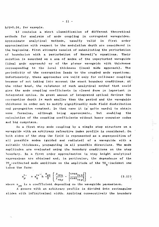
§3 contains a short classification of different theoretical
methods for analysis of mode coupling in corrugated waveguides.
Approximate annlytical methods, usually valid in first arder
approximation with respect to the modulation depth are considered in
the beginning, First attempts consist of substituting the perturbation
of boundaries with a perturbation of Maxwell's equations. Their
solution is searched as a sum of modes of the unperturbed waveguide
(ideal mode approach) or of the planar waveguide with thickness
corresponding to the local thickness (local mOde approach), The
periodlclty of the corrugation leads to the coupled mode equations.
Unfortunately, these approaches are valid only for collinear coupling
because of not taking into account the exact boundary conditions. At
the other ha nd, the existence of such annlytical method that could
give the mode coupling coefficients in closed form is important in
Integrated optics, In great amount of integrated optical deviees the
corrugation depth is much smaller than the period and the waveguide
thickness in order not to modify significantly mode field distribution
and propagation constant. ln that case it is. quite useful to obtain
sorne formulas, although bei.ng approximi:lte, but enabling the
calcula ti on of the coup ling coefficients wi thout heavy computer codes
and big computera.
As a first step mode coupllng by a single step structure on a
waveguide with an arbitrary refractive index profile is considered. On
bath si des of the step the field is represented as a superposition ·of
all possible modes (guided and radiated) of a waveguide with a
suitable thickness, propagating in all possible directions. The mode
amplitudes are evaluated using the boundary conditions on the step
boundnry, In a first order approximation in step height analytical
expressions are obtained and, in particular, the dependeJ,ce of the
TEP-reflected mode amplitude on the amplitude of the TEn-incident
takes the form:
one
( 3. Il)
where sf-IT/ is a coefficient depending on the waveguide parameters,
A groove with an arbitrary profile is divided into rectangular
slides with infinitesimal width. Applying consecutively the boundary
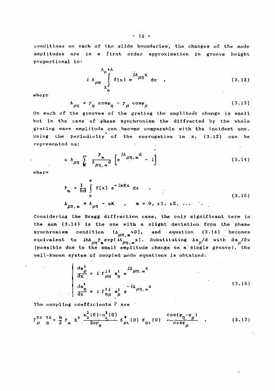
- 12 -
conditions on each of the slide boundaries, the changes of the mode
amplitudes are in a first order approximation in groove height
proportions! to:
( 3. 12)
where
A11
'11 =·r'IJ cosll11
- rJ.I cos~Jl {3.13)
On each of the grooves of the a:rating the amplitude change is small
but in the case of phase synchronism the diffracted by the whole
grating
Using
wave amplitude can
the periodicity• of
become comparable
the corrugation
represented as:
1 iA d 1] h &. Jl'IJ ~ . [e JJ?,,.. -;;------o
Jl'IJ,IIII
where
d
1 • 1 J f(x) -imKx dx li<! e .
0
wi th the incident one.
in x, (3.12) cnn be
( 3.14)
( 3. 15)
rn = O, :tl, t2 1 .. ,
Considering ttie Bragg diffraction case, the only significant term in
the sum {3.14) is the one with a slight deviation from lhe phase
synchroniem condition (AJJ'IJ,m~O), and equation (3.14} becornes
equivalent to iM111
,r,.exp{iAJ11J,.,x}. Substituting AaJl/d with fJaJl/ax
(possible due to the small amplitude change on a· single groove}, the
well-known system of coupled mode equations is obtained:
The coup ling
[TE TE p 0
da' iA x p = 1 r" •' e JliJ,m <IX PO 0
da~ -ill x . i r' J •' e Jl'IJ,a <IX OP p
( 3.16)
coefficients r are
n~ (0)-n: (O) t: ~. (0) 2wp
0 ,.,.
( 3. 17)

- 13 -
rTH TH JI " 1 3. 181
where q~=r~HP- k2n:(O), and t(O) and X(O) are the values of TE and TH
mode eigenfunctions, calculated on the waveguide surface.
The case with a polarization conversion is more complicated due
to the non-orthogonality of the longitudinal and transverse mode
eigenfunctions and a numerical treatment is required. 9 sets of
parameters of a step refractive index waveguide were considered: n1
=1,
n2
=? .. ·62 1 n3
=1.515, t~3, 5 1 10, 15 and 20 11m and n1
=1, n2
=2.234,
n3
=2.216 1 t=6 1 10, 20 and 60 J.lm 1 including mono and multi mode cases
.,( up to 8 modes). Wi thin a 5% relative error the coupling co~fficients
cnn be approximated with the following expression:
rTE TH=hT q 02(0)[--'----'-]e* (O);Jt' (O)sin[V'JI-~ijl (3,19) 11 n lm n 2 0 1(0) n2(0) /iL 'lL cos'n
' ' Formulas (3,17) and (3,18) are valid for an arbitrary refractive index
and groove profiles. (3.19) is valid for an arbitrary grating profile,
too. For the case of normal incidence they coincide with the results
of the local mode approach and of the "growing-wave" analysis of
Stegeman et al. [114]. For oblique incidence, hmo~ever, our results
differ slightly from those of Stegeman et al. by the eosine in the
denomi~ator, responsible for the interaction length l=d/coSf' for one
groove.
In many cases the modulation depth is not very small compared to
the period (e,g. grating in- and output couplers) 1 but not big enough
to,modify significantly waveguide mode structure. When h/ds0.15 it is
possible to use the phenomenological approach. These methods could be
divided into two groups with respect to the field representation:
Based of Rayleigh hypothesis (plane wave expansion)
[111-113]. This is a ·very simple method, but it has two dis~dvantages
- validity only for,step-index waveguides and bad convergence rate for
non-sinusoidal grating profiles,
2. Hodal methods solution of rigorous boundary problem is
searched numerically as a sum over modes of unperturbed waveguide (in
general it can be graded index),
- 14 -
Other two groups of methods could be specified according. to the way
the coupling coefficients are calculated:
1. Numerical determination of mode propagation constant in the
coupling region. After that coupling coefficients are calculated using
the relation r=2klm(aP) [47, 113],
2. Application of the phenomenological approach presented in §3
of Chapter two,
Comparison was made between the resulta obtained using the last
method and using. analytical formulas ( 3.17) (3.19). A very good
coïncidence is observed for three- and multilayered waveguides in the
case of shnllow corrugation when formulas (3,17) - (3,19) are valid.
Al though in the numerical treatment rigorous .electromagnetic
theories can be used, they presume an approximation which is fulfilled
if groove depth is small compared to the waveguide thickness
influence of the corrugation on mode propagation constants away from
phase mntching conditions is negligible. When the grating is deep
enough, mode propagating constants are chnnged significantly even
without mode interaction. Horeover, coupling becomes strong even when
phase matching is not ensured. In that case different modes of the
corrugated waveguide do not correspond at all to the modes of planar
system. The only possibillty is to search for a rigor6us solution for
energy trans fer in different directions in wavegulding layer,
substrate and claddlng [105, 114, 115],
- 15 -
PART TWO, ANOMAUES IN SARE l·1ETALUC GRATINGS
This part of the thesis contains a detailed study of different
anomalies in diffraction characteristics of bare metallic gratings.
Thin dielectric layer on the metallic substrate does not lead to ne\-.'
anomalies but to a slight shift of their position, depth and half
widlh. Thicker layers could support leaky waveguide modes, excitation
of Hhich could lead to appearance of new anomalies, like resonance
anomalies in corrugated dielectric waveguides (Part three). These
anomalies in metallic gratings covered with a dielectric layer ure
studied in details and we should not discuss them.
The follo\oo·ing .I::&!!!..ark has to be mentioned here: Further on
appearance of curis in energy flow dlstribution is discussed in
details, Usually existence of curis in vector field (of a vector A)
means thal rotA...:O. This is not the case with Poynting vector P of
electromagnetic field in lossless media free of charges nnd currents:
rotP,Q. Ry 'curis' for the sake of brevity h'C are naming regions of
closed vector !ines,
CfiAPTER FOUR: LITTROW MOUNT ANOMALIES - PERIODICITY OF
PROPERTIES AS A FUNCTION OF GROOVE DEPTH
It is well-kno1m that the re is a quasi periodici ty of
diffraction efficiency of grating supporling t1w diffraction .orders.
Existence of very hi~l efficiency in Littrow mount is accompanied by a
zero of the zeroth reflected arder, Effort of Hesse! and Oliner [2BJ
to explain this 'anomaly' (called perfect blazing in Littrow mount or
Bragg• type anomal y) br surface wave excitation failed and la ter they
proposed another interpretation - zeroth arder zeros in Littrow mount
are connected with improper poles of the scaltering matrix. These
pales are obtained when incident and reflected waves are exchanged,
i.e. IJOn-physical radiation conditions are implied. It is shown in the
tbesis Uml this correspondence between zeros of the reflected arder
nnd improper pole does not contain any explanation and happens always
Hlwn incident and refJ~cted ~aves arc exchanged:
Nat.hemalically this exchange is expressed as a change of the
sign of incident ~-rave vector compone nt <o' perpendiculnr to the
grating plane. If zero th arder amplitude is zero ( b 1 =0) for o =a2
0 0 0 ,,. i t. h
non-7.ero incident wave (a~:: 1) the.n forma! exchauge of incidelll and
- 16 -
reflected wave (carried out with the change of sign of x0
) means that
the re is a reflected wave without an incident one, i.e. nn
eigensolution exists represented by a pole of the improper scattering
matrix. This fact is of great importance for the results presented in
the next two chapters, where it is shawn that a close connection
èxists between resonance and non-resonance non-Littrow mount
anomalies.
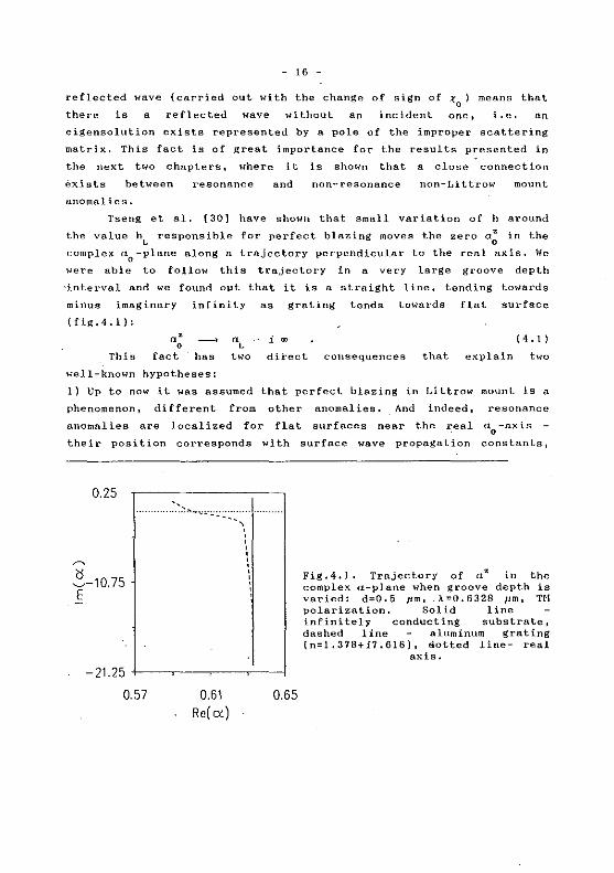
Tseng et al. {30] have shawn that small variation of h around
the value hL responsible for perfect blazing maves the zero a~ in the
complex a0
-plane along a trajectory perpendicular to the real axis, We
were able to follow this trajectory in a very large groove depth
'interval and we found opt that it is a straight line, tending towards
minus imaginary infinity as grating tends towards flat surface
(fig,4.1):
This
a: __. fact has
well-known hypotheses:
i ro
dii'ect
( 4 . 1)
consequences that explain two
1) Up to now it was assumed that perfect blazing in Littrow mount is a
phenomenon, different from other anomalies. And indeed, resonance
anomalies are localized for flat surfaces ne ar the real a0
-axis
their position corresponds with surface wave propagation constants,
0.25
(j ~-10.75 E
-21.25
0.57 0.61 Re( ex)
' ' ' ' ' ' ' ' ' ' ' ' '
0.65
Fig.4.1. Trajectory of a~ in the complex a-plane when groove depth is varied: d=0.5 fim, :\=0.6328 11m, n1 polarization. Solid line infinitely conducting substrate, dashed 1 ine aluminum grating (n=1.37B+i7.616), tlotted line- real
axis.
- 17 -
while the 'starting' point of Littrow mount perfect blazing lies in
- iCll.
2) Littrow mount anomalies appear only in deep gratings, when a: approaches the real axis and has sorne influence on diffraction
effü:iencies.
Increasing the groove depth, a: approaches the real axis with
rate determined by the following connections:
l Re(az) =a
0 L
2" Im(az) f ~ -1 À. 0 - 1
( 4. 2)
where f_1
is the -lst Fourier component of grating profile fonction.
These equations are fulfilled only till the zero is lying away from
the ·real axis. When Im(a~) becomes small enough its decresing rate
depends on the polarization. For a fixed value of h it crosses the
real axis perfect blazing in the -lst arder appears. After that
Im(a~) increases in a positive direction, zeroth arder efficiency is
growing and -lst arder efficiency decreases.
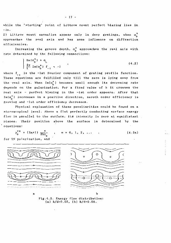
Physical explanation of these peculiarities could be found on a
microscopical leve!. Above a flat perfectly conducting surface energy
flow is parallel to the surface. Its intensity is zero a\:. equidistant
planes. Their position above the surface is determined by the
equations:
{ 2m+l) n 2k-t
0
rn
for TH polarization, and
• b
Fig.4.2. Energy flow distribution: (a) h/d=0.02, (b) h/d=0.08.
(4.3a)
- 18 -
n ~
0
rn 0' 1. 2' 14. 3b)
for TE polerization.
For small corrugation, the li nes {that re present the
cross-S€ction of energy flow surfaces with plane perpendicular to the
grating) in the near vicinity of the surface are parallel to it
(fig.4.2a), Vertical component of Poynting vector PY becomes different
from zero except for the positions above the tops and bottoms of the
grooves. In the thesis it is shawn that each plane, defined by
eq.(4.3) is split into two, the splitting increases with h. Between
each couple of planes Px has a negative sign (fig.4,2b). As a result
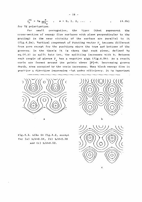
curls are formed around the points where IP!=O. Increasing groove
depth, aren occupied by the curls increases. They black energy flow in
positive x dii'ection increasing -lst order efficiency. It is important
a
Fig.4.3. Like in fig.4.2, except
for (n) h/d=0.24, (b) h/d=0.38
and (cl h/d=0.52.
b
c
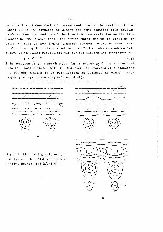
- 19 -
ta note that independent of groove depth value the centers of the
lowest curls are situated at almost the same distance from grating
surface. When the centers of the lowest bottom curls lie on the line
cannecting the groove tops, the entire upper medium is occupied by
curJs the re is now energy trans fer towards reflected wave, i, e,
perfect blazing in Littrow mount occurs. Taking into account eq.4.3 1
groove depth values responsible for perfect blazing are determined by:
h :. TE, TH Yo ( 4.4)
This equation is an approximation, but a rather good one numerical
results almost coincide with it, Horeover, it provides an explanation
1~hy perfect blazing in TE polarization is achieved at almost twice
deeper gratings (compare eq,4,3a and 4.3b).
a
Fig.4.4. Like in fig.4.2, except
for (a) and (b) h/d=0.72 (in non
Littrow mount), (c) h/d=1.44 .
..
·~··· ··.\@)···· b
c
- 20 -
Further increase of groove depth causes bottom curls to go
deeper and deeper. The distance between the centers of bottom and top
curls decreases and they are unfolded energy flow in positive
direction increases. Energy flow distribution becomes more and more
alike the distribution above shallow gratings, but only ÔUtside the
grooves. When ~2y0 the centers of the top and bottom curis lie on one
and the same line (fig.4,4a) and curls above the groove tops
disappear. In that case the grating acta like a plane mirror. Inside
esch groove there is a totally hidden curl that separates energY flow
above the grating from the groove bottoms, These curls are very stable
- changing angle of incidence in a large interval causes no change in
.f.he flow distribution. This property called 'antiblnzing' (118] is
important for sorne effects discussed in the next two chapters.
Increasing. groove depth leads to a repeating of fig.4,2· to
fig.4.4 process, except for the lowest curls Soing deeper and deeper,
"Perfect blazing followed by ·antiblazing etc. could be detected
(fig.4,4c) agnin.
It is shawn in the thesis that when the grating supports a
single order 1 in the near zone curls are formed periodically in the
same manner like in figs. 4.2 4.4. They lead to a periodical
behsvior of the ~ of reflected wave, It must be pointed out that
perfect conductivity is not a. limitation neither of the ·method nor of
the resulta i t is assumed in order to mnke the pic ture of flow
distribution more clea.r as there are no lines fini~hing at the
surf" ace, For finitely conducting gratings the behavior of flow
distribution is almost the same, Horeover, in chapter 9 it is
demonstrated that suc~ formation of curla is typiCal for sorne peculiar
cases of light diffraCtion by dielêctric gratings, too,
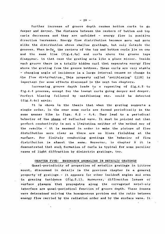
CHAPTER FIVE: RESONANCE ANOMALIES IN HETALLIC GRATINGS
Quasi-periodicity of properties of metallic grati~gs in Littrow
mount 1 discussed in details in the previous chapter is a general
property· of gratings - it 8.ppears for other incident. angles and even
·in grazing incidence (f,ig.5,1), Horeover 1 · diffraction lasses of
surface plaamon that propagates along the corrugated metal-air
interface are quasi-periodical fonction of groove depth. These !osses
were determined" solving the homoSeneous problem and the ratio between
en~rgy flow carried by the radiation" arder and by the surface wave, It
~ u c
1.0
-~. 0.5 iE u
0
0 0.65 h/d
- 21 -
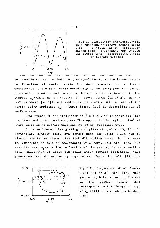
Fig.S.l. Diffraction characteristics as a fonction of groove depth: solid line Littrow mount efficiency, dashed line - efficiency for a=0.99 and dotted line - diffraction !osses
of surface plasmon.
is shawn in the thesis that the quasi-periodicity of the lasses is due
to formation of curls inside the deep grooves. As a direct
consequence, there is a quasi-periodicity of imaginary part of plasmon
propagation constant and loops are formed in its trajectory in the
complex a0
-plane as a function of groove depth (fig. 5. 2), In the
regions where JReaPj<l eigenvalue is transferred into a zero of the
zeroth arder amplitude a~
surface wave.
large lasses lead to delocalization of
Some points of the trajectory of fig,5.2 lead to anomalies that
are discussed in the next chapter. They appear in the regions IImaPI<1
where there is no surface wave and are of non-resonance type.
It is well-known that grating multiplies the pales [19, 20]. In
particular, similar loop~ are formed near the point 1-;\/d due to
plasmon excitation through the +1st diffraction arder. In that case
the existence of pole is accompanied by a zero, When this zero lies
near the real a0
-axis the reflection of the grating is very small -
total absorptio!l of light can occur under certain conditions. This
phenomenon was discovered by Maystre and Petit in 1976 [38] for
0.09
g-0.02 !':
-0.13
0.75
h/d ------7 O._H
1 O.JS2B
cx' "
!.OB
0.90 Re( <X}
1.05
Fig.5.2. Trajectory of aP (heavy
line) and of az (thin line) when
groove depth is increased. The eut
in the complex plane that
corresponds to the change of ~ign
of t0
(121] is presented with dash
li ne.
Bd
4d
0
- 22 -
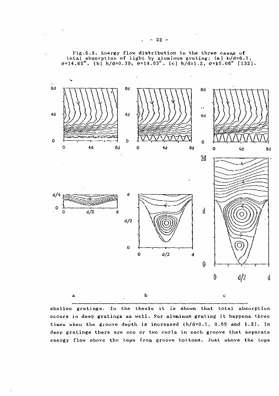
Fig.5.3, Energy flow distribution in the three case.s of total absorption of light -by aluminum gratinS: (a) h/d=O ,1,
9=14.82°, (b) h/d=0.79 1 6=14,93°. (c) h/d=1.2, 9=15.06° [132}.
Bd
4d
0 0 4d Bd 0 4d Bd 0 4d
2d
d~·1~1 9 d
r d 0 d/2 d
d/2 ~-; '\ '/ "". 0
0 d/2 d
0
0 d/2
a b c
Bd
d
shallow gralings, In the thesis it is shawn that total absorption
occurs in deep gratings as well. For aluminum grating it happens three
times when the groove dePth is increased {h/d=O.l, 0.69 and 1,2). In
deep gratings there are one or two curls in each groove that separate
energy flow above the tops from groove bottoms, Just above the tops
' J
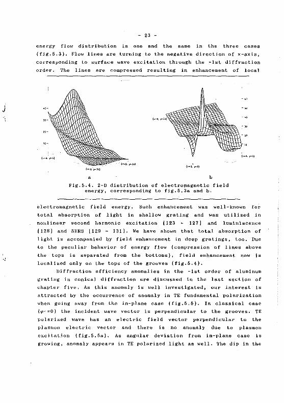
- 23 -
energy flow distribution is one and the same in the three cases
(fig,5,3), Flow lines are turning to the negative direction of x-axis,
corresponding to surface wave excitation through the -lst diffraction
arder. The l ines are compressed resul ting in enhancement of local
a b
Fig.5.4. 2-D distribution of electro~agnetic field energy, corresponding to fig.5,3a and b.
electromagne_tic field energy, Such enhancement was well-known for
total absorption of light in shallow grating and was utilized in
nonl inear second harmonie ex ci tati on ( 123 127] and luminiscence
(128] and SERS [129 - 131). We have shawn that total absorption of
light is accompanied by field enhancement in deep gratings, too, Due
to the pecul iar behavior of energy flow (compression of 1 ines above
the tops is separated from the bot toms), field enhancement now is
localized only on the tops of the grooves (fig.5.4),
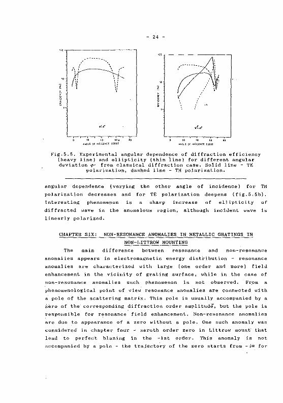
Diffraction efficiency anomalies in the -1st arder of aluminum
graling in conical diffraction are discussed in the last section of
chapter five, As this anomal y is well investigated, our in te rest is
attracted by the occurrence of anomaly in TE fondamental polarization
when goiug away from the in-plane case (fig, 5, 5), In classical case
('{l' =0) the incident wave vector is perpendicular to the grooves. TE
polarized wave has an electric field vector perpendicular to the
p]asmon elect.ric vector and there is no anomaly due to plasmon
excitation (fig.5.5a). As angular deviation from in-plane case is
growing 1 anornaly appears in TE polarized light as well. The dip in the
•vc,------------,
~',o'
lD 10 "• " •..OH Ol ._,,,.,_(( IO{GI
- 24 -
' g '
" "
Fig.5,5. Experimental angular dependence of diffraction efficiency (heavy line) and ellipticity (thin line) for different ~ngular deviation 'P' from classical diffraction case. Solid line - TE
polarization, dashed line - TH polarization.
angular dependence ( varying the other angle of incidence) for TH
polarization decreases and for TE polarization deepens (fig.5.5b),
Interesting phenornenon is a sharp increase of ellipticity of
diffracted wave in the anomalous region, although incident wave is
linearly polarized,
CHAPTER SIX: NON-RESONANCE ANOMALIES IN HETALLIC GRATINGS IN
NON-LITTROW MOUNTING
The main difference between resonance and non-resonance
anomalies appears in electromagnetic energy distl-ibution - resonance
anomalies are characterized with large (one arder and more) field
enhancernent in the vicinity of grating surface, while in the case of
non-resonance anomalies such phenomenon is not observed, From a
phenomenological point of view resonance anomalies are çonnected with
a pole of the scattering rnatrix. This pole is usually accompanied by a
iero of the corresponding diffraction arder amplit\ldè', but the pole is
responsible for resonance field enhancement. Non-resonance anomalies
are due to appearance of a zero without a pole. One such anomaly was
considered in chapter four zeroth arder zero in Littrow mount· that
lead to perfec·t blazing in the -lst orâer. This anomaly is not
accompanied by a pole - the trajectory of the zero starts from -ioo for
- 25 -
flat surface. The anomalies discussed in this section are of another
type - they are also due to a zeroth arder zero without a pole, but
the trajectory of such a zero alternatively consists of pales
(fig.5.2), We should now consequently discuss sorne peculiar points of
this·trajectory. It is obvious that such anomalies appear only for TH
polarization in the case of bare metallic gratings.·
Often diffraction gratings are used in grazing incidence for
improving grating dispersion. Unfortunately as angle of incidence
tends to 90° the zeroth arder efficiency tends to unity and -lst arder
efficiency rapidly decreases, Numerical optimization of blazed and
sinusoïdal aluminum gratings was clone [1391 ând the results could be
surnmarized as follows:
1. Sinusoldal profile is preferable lfhen grating supports two
diffraction orders.
2. Increase of groove density leads to a higher diffraction
efficiency, but shifts the worklng spectral region towards shorter
wavelength and increases sensibility to groove depth values.
3. Diffraction e_fficiency in TH polarizA.tion exceeds more than 10
times the efficiency in TE polarization.
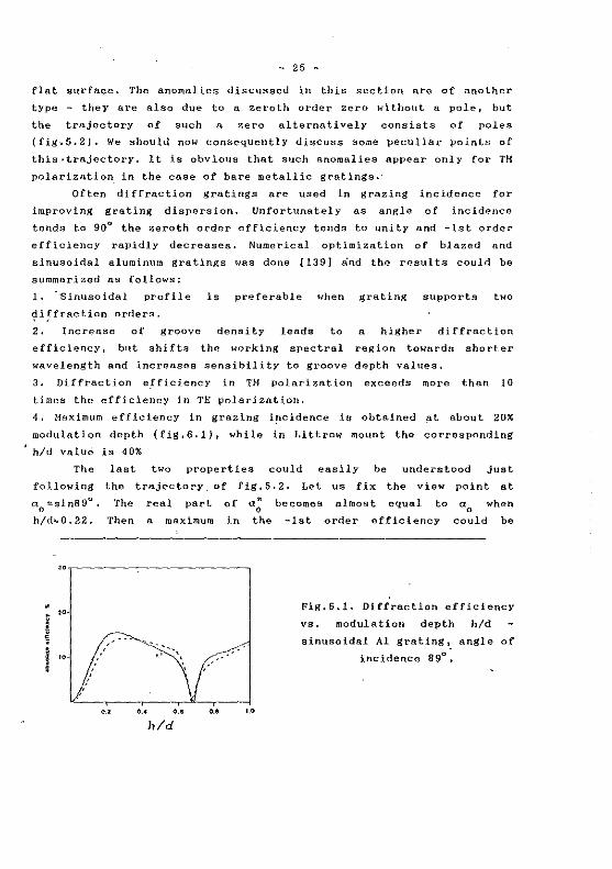
4, Maximum efficiency in grazing i11cidence is obta.ined at about 20%
modulation depth (fig, 6.1), wh ile in Littrow mount the correspondlng
h/d value is 40%
The
following
a0
=sin89°,
h/d .. 0,22.
00
"
i " f " '
last two properties could easily be understood just
the trajectory. of fig.5.2. Let us fix: the view point at
The real part of a' 0
Th en a maximum in the
.. \
,, '·' ... •.. '·'
be cornes al most equal to a wh en 0
-1st order effic!ency could be
Fig.6.1. Diffraction efficiencY
vs, modulation depth h/d
sinusoidal Al grating, angle of
incidence 89°,
- 26 -
expected. Ils value is deterrnined mainly by Im(a~) o.nd Hhep absorption
!osses in the metal are growing Irn{a~) becomes greater and -lst order
efficiency decreases, As far as such o. trajectory (fig.5.2) is typical
only for TM polarizatioJ) and for TE polarization there is no zeroth
arder ;ero lying in the vicinity of a0
, TH -lst arder efficiency is
much higher.
Further increase of h/d rnoves a; a.way from a0
=sin89°, zero th
order amplitude increases (a.s it depends on the difference a0 -a~) and
-lst order efficiency decreases {fig.6.1). Because the trajectory of
the zero a" is nlmost parallel to the real a axis when h/d~o.z, 0 0
groove depth dependence of efficiency is rather smooth. This fa. ct
could be of great pra.ctical interest as it is very difficult to
produce n grating with preliminary fixed groove depth.
Tracing the trajectory \<o'ith increase of groove depth, it crosses
the real nxis when h/d,.0.39. The cross-point a~ 1 corresponds to the
so-called 'perfect blazing in non-Littrow mount' discovered in 1980
[37). \\'e were nble to find its proper exp~anntion (fig,5.2) and to
show why perfect bla.zing in TE polnrization exists only in Littrow
mount. It is interesting to note thal perfect blazing ·in Littrow and
non-Littrow mount are exhibited nt almost one and the same groove
depth values thus angular interval with high diffraction efficiency is
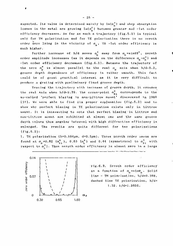
enlarged. The results are quite different for two polarizations
(fig. 6. 2):
1. TH polarization (h::0.194pm, d=O.Srm). Three zeroth order zeros are
found at a0
=0.B2 (a;1
), 0.63 (u1:) and 0.44 (symmetrical to a;
1 with
respect to a1~). Thus zero th arder efficiency is al most zero in a large
0.14 ~ u c 1 ~ u 1
"' " ~
0.07
1' 0
0
l ~ N
0
0.30
1 1 ' j
0.65 1.00
Fig.6,2. Zcroth order efficiency
as a fonction of a =sine . Solid 0 0
line- TH polnri~ation, h/d=0.38B,
dashed line TE polarization, h/d=
1.32. l/d=l.2656.
'
- 27 -
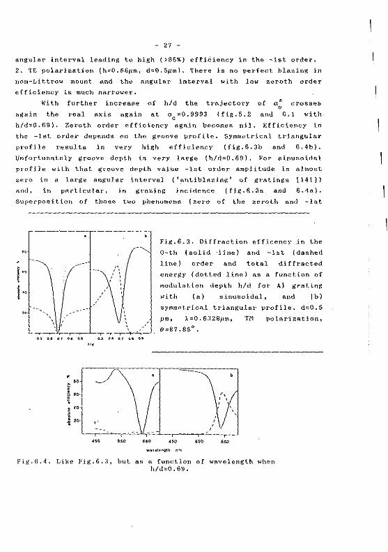
angular interval leading to high ()85%} effièiency in the -lst order.
2. TE polarization (h::o0,661-Jm, d=0.5pml. There is no perfect blazing in
non-Littrow mount and the angular interval with law zeroth order
efficiency is much narrower.
With
agnin the
h/d=0.69).
further increase of h/d the trajectory
real axis again at ac=0.9993 (fig.5.2
Zeroth arder efficiency again becomes nil.
of a; crosses
and 6.1 with
Efficiency in
the -lst order depends on the groove profile. Symmetrical trîangular
profile results in
Unfortunately groove
very
depth
high efficiency (fig.6.3b
is very large (h/d=0.69), For
and 6.4b).
sinusoidal
profile with that groove depth value -lst order amplitude is almost
zero in Il large angular interval ('antiblazing' of gratings [141))
and, in po.rticular, in grazing incidence (fig.6.3a and 6.4~),
Superposition of those two phenomena (zero of the zerot.h and -lst
" '. ' '
,' '
t>• o.• 01 oo •u o.~ o• O_l 11• (IS
'"
•
,.
'" "'
Fig.6.3. Diffraction efficency in the
Q-th 1 sol id ·li ne) and -lst (dashed
li ne) order and total diffracted
energy (dotted line) as a function of
modulation depth h/d for Al gratinS
with (a) sinusoïdal, and (b)
syrnmetrical triangular profile. d=0.5
pm, l=0.632Bjlm, polnrization,
9=87.85°.
Fig.6.4. Likc Fig,6.3, but as a function of wavelength when h/d=0.69.
- 28 -
arder amplitudes) lead to almost total absorption of incident light by
a grating supporting two diffraction orders. lt appears when the
trajectory of a~ in fig.5.2 lies to the left of the eut and there is
no pole. 'l'hat is why there is no field enhancement - this anomaly is
of non-resonance type. Contrary to the cases of total absorption
discussed in Chapter 5 now there is no surface wave excitation and
energy flow lines are not compression of flow lines near the grating
surface.
CHAPTER SEVEN: ANOMALIES INTERACTION IN HETALLIC GRATINGS
This chapter deals with the influence of simultaneous
,appearance of two anoma.lies on the diffraction characteristics. It is
"''ell known that interaction of eigensolutions lead to splitting and
repelling of trajectories of the cor;esponding eigenvalues due to
orthogonality requirements. Such a behnvior is characteristic not only
for the pales of the sco.ttering matrix, but of zeroth reflected arder
r.eros as well, as shawn in §1. The reason is that these zeros are in a
peculiar manner eigenvalues 1 but of the non-physical problem (Chapter
four). Such an interaction between the trajectories of the zeros is
guite important, as far as in many of the anomalies the influence of
fhe zeros is greater than tho.t of the pales.
Simulta.neous excitation of two opposite~y propag·a.ting S\trface
plasmons along shallow gratings and its influence on anomalies in
reflectivity is discussed in §2. Energy transfer bet~een· the two
,urface waves leads to a sharp increase of imaginary parts of their
propagation constants. The pole maves away from the real axis and
surface wa.ve excitation becomes more difficult and anoma1y dip in the
reflectivity becomes less noticeable
corresponding to the interaction region
w-mini gap is formed.
in thespectral interval
the so-called forbidden
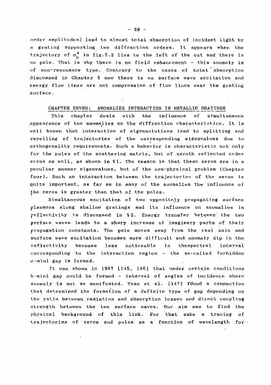
It wa.s shawn in 1987 [145, 146) that under certa.in conditions
k-mini gap conld be formed - interval of angles of incidence where
anomaly is ·not so ma.nifested. Tran et al. [147] fcJund a connection
that determined the forma. lion of a defini te type of gap depending on
the ratio between radiation and o.bsorpt.ion lasses and direct coupling
strength between the two surface wnves, Our aim was to find the
physica.l background of this link. For that sake a tra.cing of
t.rajectories of ·zeros and pol es as a function of wavelength for
- 29 -
0.01
~---~-~-*-~~K---*---U\)._..,lll_
.. ~ •• - - a 0 - - ~ w ••
~ w ~ - -. - -~o~-~- -l'f --~--x---~- __ ,..
-0.01
-0.045 0 Re( <X)
0.045 Fig. 7. l a) Pole (dashed
' -· ' '"
~.
.. ;.. lfO
'"
lines) and zero {solid line}
trajectories aS a function
of wavelength (shown in nm),
Sînusoidal grating, h=0.06
pm. b) Corresponding wave
length - angle of incidence
de};lendence of reflectivity.
b
fferent groove depth values and profiles is presented ne.a.r normal
~idence. Coupling between incident and surface waves ~s direct
)rough the :!:lst f·~urier components of grating profile f±1
), Coupling
ween oppositely propagating surface plasmons is of two types:
ect (carried out through the second Fourier components of the
file f±l' if any) and indirect (through 2f±i J. We are dealing with
- 30 -
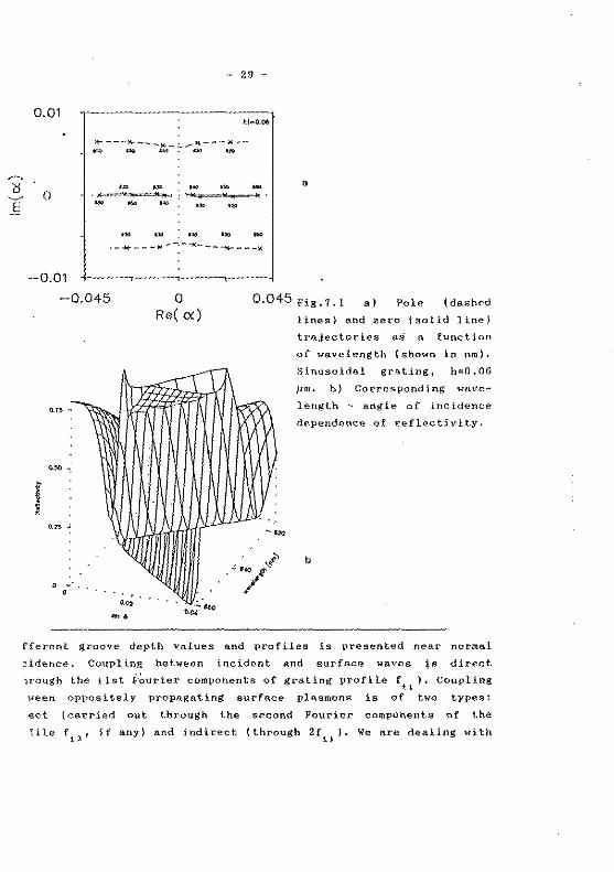
nluminum grating with period d=0.63 11m and profile function:
h, 2n h, . ['" ( !!s)] f{x)=zsin(a x) + 2 Hn d x + q q=O, 1 ( 7. 1)
If q=O ..... then f(x) is anti symmetrical, and if q=l symmetrical. At
first h2
is nil and coupling between incident and surface \;aves is
much stronger than between the surface waves, provided the grating is
shallow, Thus the repelling of trajectories of the poles lfig.7.ln) is
determined predomina.ntly by radiation and diffraction !osses, but not
b
Fig.7.2. Like fig.?.l, except fo profile given by eq. {7,1) with h
2=0,02 jJm.
0.021
0
-0.021
-0.04 0 Re( ex )
0.04
A111l_~ n. ('r~ \1htfr .,~
f ~ nzo;-:
~
.- ~20 ,, ' - 1/
- tl~o '-t
_,./ 0.02
'" • '"" '"
- 31 -
by a plasmon coupling even near normal incidence, Similar behavior
have the zeros except for the groove depth value h1
=0.06 pm. Then
their trajectories are lying near the real axis and in the vicinity of
a0
=0 their separation becomes so small that even weak indirect
coupling leads to the repelling: angular interval around a0
=0 exists
without real zeros, the value of minimum in the reflectivity increases
and k-mini gap is formed (fig.7,lb),
It has to be pointed out that existence of forbidden gap for the
anomnly in the reflectivity in this case does not correspond to a
forbidden gap in the surface plasmon propagating ·constant aP - pole
trajectories do not exhibi t any noticeable pecul iari ti es, Th us i t
could be risky to determine the values of real and imaginary part of
aP from experimental results for position, half width and minimum
va]\le of the reflectivity dip.
When direct coupling between surface "'aves is greater (h1 i!!"O)
repelling of the pole trajectories appears (fig,7.2a), practically
independent on the strength of indirect coupling, In agreement with
general theoretical principles, strong interaction between zeros could
be found 1 too. In the vicinity of a0
=0 trajectories of the zeros
approach the trajectories of the poles and mutual annihilation leads
lo a formation of spectral interval without anomalies w-mini gap
region appears (fig.7.2b). A peculiar mechanism of transition between
two types of gaps with the increase of h2
is discussed in the thesis.
Anomal y interactions in deep metal! ic gratings is analyzed in
§ 3. For shnllow grooves repelling of trajectories could be noticed
only in the ne ar vicini ty of the ir "intersection" points. For deep
gratings interaction region is much larger. It is shown in the thesis
how different types of coupling between poles and zeros determines
short- and long-wavelength limits of different anomalies:
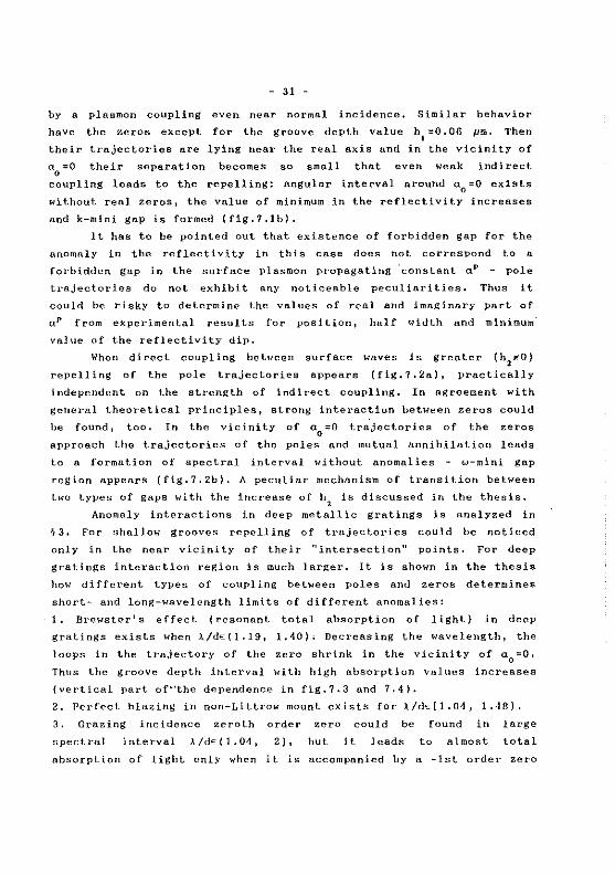
1, Brewster's effect (resonant total absorption of light} in deep
gratings exists when J../dE:(1.19, 1.40); Decreasing the wavelength, the
loops in the trajectory of the zero shrink in the vicinity of a0
=0,
Thus the groove depth interval with high absorption values increases
(vertical part of•'the dependence in fig. 7. 3 and 7. 4).
2. Perfect blazing in non-Littrow mount exists for J../d~[l.04, 1.48).
3, Grazing incidence zero th arder zero could be found in large
spectral interval À/dE(l.04, 2), but it leads to almost total
absorption of light only when it is accompanied by a -lst order zero
- 32 -
.... ------------,
,,
'~»>»==~====~~~====~====~'" -\t<'>;'"'"'"')
• b
Fig, 7, 3. Spectral dependence of groove .- depth values (a) and angul/;\ deviation from -lst order eut-off (h), corresponding to total ligl
absorption in shallow and deep aluminum grating,
(for aluminum sinusoidal grating it hnppens when À/d=1.2656~
- 33 -
PART THRΠANOMAUES IN DIEUECTRIC GRATINGS
CHAPTER EIGHT: RESONANCE ANOMALIES IN CORRUGATED OPTICAL
PLANAR WAVEGUIDES
· In multilayered dielectric gratings resonance anomalies are due
to guided wave excitation. Two are the main differences with bare
metallic gratings:
1. Corrugated waveguides can support bath TH and TE modes thus
resonance anomalies appear in bath polarizations.
2, Huch smaller value of !osses in optlcal dielectric waveguides
compared to metallic substrate enables the existence of pole aP to
mnnifest itself rather more noticeably - anomalies consist of peaks
and~~dips, contrar:{ to resonance anomalies in metallic gratings where
~h~se peaks could not be detected or are rather weak.
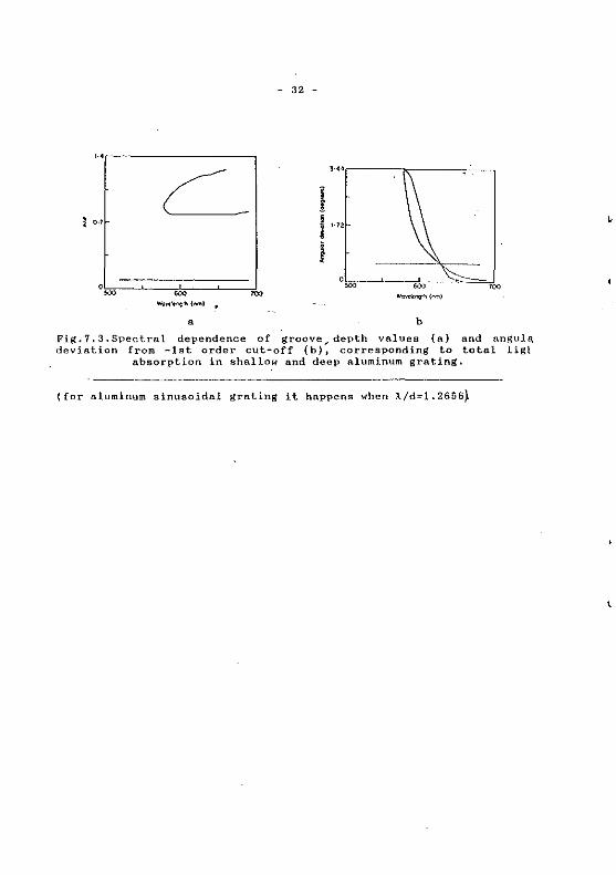
Fig.8.1. Reflectivity in conical
mounting of corrugated wavefuide,
n1
=n3
=1,
h=0.04pm,
n2
=2.3, t=O.lJlm, d=0.3pm,
l=0.6J1m, unpolarized
light.
..
'"
The peak is mu~h more pronounces when it is accompanied by a low
valued background. Host peculiar is the behavior of reflectivity
(fig.8.1), Two cases are discussed in the thesis in details - grating
supporting only the zeroth orders in the cladding and in the
substrate, and having more diffraction orders. Phenomenological
approach makes it possible to draw sorne general rules connecting
symmetry of the system wi th the main characteristics of. anomal y,
provided only the ~ieroth orders are propag11ting:
(a) symmetry with respect to horizontal axis (e,g, symmetrical
waveguide with anti-symmetrical groove profile on upper and lower
boundary) - reflectivity minimum is always zero •
.(.hl .R.S.:~M~.e.t.rt" l.'J..tb respect to vertical plane ( e. g, asymmetrical
- 34 -
waveguide with symmetrical corrugation) - reflectivity maximum reaches
100%, at !east theoretically.
(c) symmetry with respect to horizontal plane (it is difficult to
produce such a waveguide) - reflectivity changes from 0 to lOO% in the
anomalous,region.
Of course, these conclusions are valid only for lossless waveguides
and for plane incident wave.
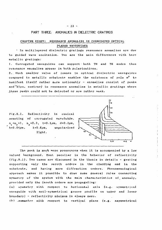
§2 presents experimental results of resonance anomaly in graded
index waveguide. After a grating with 0.3 /JID period was recorded
interferometrically ill a layer of positive photoresist Shipley AZ1350 1
il was transferred into the glass substrate using ion-bearn milling.
Honomode waveguide was made in the corrugated substrate using ion
exchange in molten AgN03
• Angular and spectral dependencies of
reflectivity in the region of waveguide ~ode excitation are shawn in
fig.8.2, Half width of the maximum is about 3 nm - much narrower than
the other tunable reflection optical filters.
If the period of the grating is lan~er and higher orders are
propagating 1 the ru les that are connec ting the properties of anomal y
with symmetry of the system are valid only for shallow grooves, A
demonstration of this fact is presented in §3 of chapter 8. It is
... ,----------~
'"
a
Fig,8.2. Angular {a) dielectric grating,
"
'"' "" "" ."'"""'"'''
b
and spectral (b) dependance of reflectivity of Dashed line without waveguide, solid line
after the ion-exchange.
•
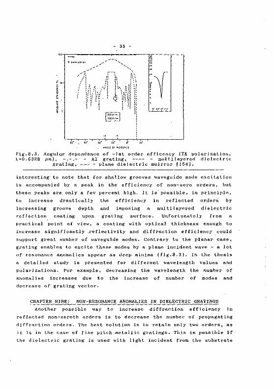
Fig.8.3. :\=0.6328
- 35 -
"'1-=~-------------.--------------r,r------.----,
ü
:: ·~ ' ' " ' • l '
~ ,,,.,,.,,.,,
.,. ,.
~· ~·· , ... ~
., .. . ,.
Angulur dependence of -lst arder efficency (TE polnrization, pm). - -.- Al grating, multilayered dielectric
grating, ----plane dielectric muirror [154].
interesting to note that for shallow grooves waveguide mode excitation
is accompanied by a peak in the efficiency of non-zero orders, but
these peaks are only a few percent high, It is" possible, in principle,
to increase drastically the efficiency in reflected orders by
increasing groove depth and imposing a multilayered dielectric
reflection con ting upon grating surf6ce. Unfortunately from a
practical point of view, a coating with optical thickness enough to
increase significantly .reflectivity and diffraction efficiency could
support great number of waveguide mo.des. Contrary ta the pl anar case,
grating enables ta excite these modes by a plane incident wave - a lot
of resonance anomalies appear as deep minima (fig.8.3). In the thesis
a detailed study is presented for different wavelength values and
polarizations. For example, decreasing the wavelength the number of
anomalies increases due to the increase of number of modes and
decrease of grating vector.
CHAPTER NINE: NON-RESONANCE ANOHALIES IN DIELECTRIC GRATINGS
Another pos~ible way to increase diffraction efficiency in
reflected non-zeroth orders is to decrease the number of propagating
diffraction orders. The best solution is to retain only two orders, as
it is in the case of fine pitch metallic gratings, This is possible if
the dielectric grating is used with light incident from the substrate
- 36 -.
side under the angle higher than the critical one for total internai
reflection. Provided the period is small enough, there .is no
propagating order in air and in the substrate only two orders exist.
Like metallic gratings supporting two orders, highest diffraction
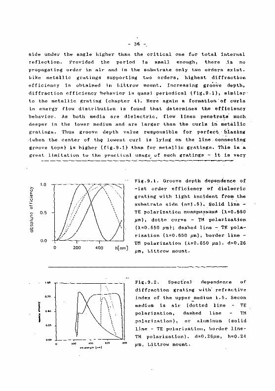
efficiency is obtained in Liltrow mount, Incrensing groove depth 1
diffraction efficiency behnvior is quasi periodical (fig.9.1) 1 similar·
to the metallic grating (chapter 4), Here again a formation'of curls
in energy flow distribution is found that determines the efficiency
behavior. As bath media are dielectric, flow lines penetrate. much
deeper in the lower medium and are larger than the curls 1n metàllic
gra.tings, Thus groove depth value responsible for perfect biazing
.(when the center of th~ lowest curl is lying on the line. connecting
groove tops) is higher (fig.9.1) than for metallic gratings, This is a
grent limitation to the prnctical usage ... of such gratings - it is very
~ u < ru .~
• ru
3 0 ~ D 0
1.0
0.5
/ /'' 0.0 .
0 200 400 h(nm]
·~ ,-------~----,
., L~ i ...
Fig. 9.1. Groove depth depe_ndence of
-lst arder efficiency of dielecric
grating with light incident fro~ the
substrate side (n=1.5)', Solid line
TE pole.rization nonflpll?SUHA . ().=0. 550
Jlm), dot te curve - TH polarization
().=0.550 J,lm); dashed line -.TE pola
rization 0.=0, 650 Jlm), border li ne -
nt polarization (;\.=0.650 pm). d=0.26
pm 1 Littrow mount.
Fig,9.2. Spectral· dependence of
diffraction grating with. refractive
index of the upper~medium 1.5. Secon
medium is air (dotted line TE
polarization 1 dashed li ne TM
polarization), or aluminllm (sol id
line - TE polarization, border line
TM. polarization), d=O. 26pm, h=O. 21
Jlm, Littrow mount.
- 37 -
difficult to manufacture grating with small period (d~0.25 Jlm) and
high modulation depth (h/d-..1). The main advantage lies in the fact
that here absolutg efficiency could reach 100% value - lasses are much
lower than in metallic gratings,
Spectral dependence of efficiency in Littrow mount is presented
in fig,9.2 for a fixed groove depth value. It looks like efficienèY in
TE polarization for metallic gratings and this could easily be
understood taking into account that much broader maximum for TH
polarization 'of metallic grating is due to the existence of
non-Littrow perfect blazing (see chapter 6), This phenomenon is
connected in a peculiar manner with existence of surface plasmon on
bare plane metal-air interface. As far as auch surface waves could not
prof:ia.gate along the interface between two dielectrics, non-Littrow
perfect blazing is not detected in fig.9,2 for the case of dielectric
grat.tng,
CHAPTER TEN: ANOMALIES AND HODE INTERACTION IN CORRUGATED
PLANAR WAVEGUIDES
This chapter presents results on two aspects of mode coupling in
corrugated planar waveguides:
1. Influence of simultaneous excitation of more than one mode on the
resonance anomalies,
2. Brewster's effect in corrugated waveguides anomaly in the
coupling coefficients of mode interaction in the corrugated region of
a planar waveguide.
For multilayered planar waveguide it is possible to have
differently polarized modes with equivalent propagation constants,
provided the parameters are properly chosen, In §1 this possibility is
utilized to obtain resonance anomalies in the reflectivity for the two
fundamental polarizations important when working in unpolarized
.light.
If phase conditions for mode excitation are satisfied near
normal incidence, then two oppositely propagating modes ar~ excited
simultaneously. Tt:ls mounting enables to use the narrow band
reflection filter (chapter 8) dlrectly as a selectable mirror (for
example 1 in laser resonators). Anomaly 'interaction leads to appearance
of two peaks. At a certain set of parameters annihilation of pales and
zeros happens, like formation of ~-minigap in metallic gratings.
- 38 -
Fortinately, for symmetrica.l corruga.tion profile only Q.ne peak is
formed in spectral dependence of the reflectivity,
Brewster' s effect in corruge.ted pl anar wnveguides is discussed
in ~ 3, When TE modes are coupled in a corrugnted region of a planar
waveguide)- at a given angle between their directions of propagation
the coupling vanishes. This phenomenon ha.s been known for yea.rs, but
there is nor proper understanding, neither a common opinion on this
angle value.
The form of the angular dependencies in {3.17)- {3.19) hns two
direct consequences:
(i) co- and contra-linenr int~ractions are cnrried out with a
polarization conservation, and
(ii) if the angle between the directions of propagation is equal to
n/2 the coupling between TE modes vanishes. From eq. (3.17) it follows
tllftt the effect is valid for bath the coupling of modes with the snme,
and wilh different orders, Furthermore, even on a single, step boundary
(eq.(3.11)) TE mode coupling vanishes as. the angular difference
becomes 90°, As far as the existence of grating leads to n
constructive {or destructive) interference between the· diffracted on
each groove modes, it is obvious that in the case of the zero coupling
on a single boundnry no interaction would appea.r throughout the whole
corrugated region.
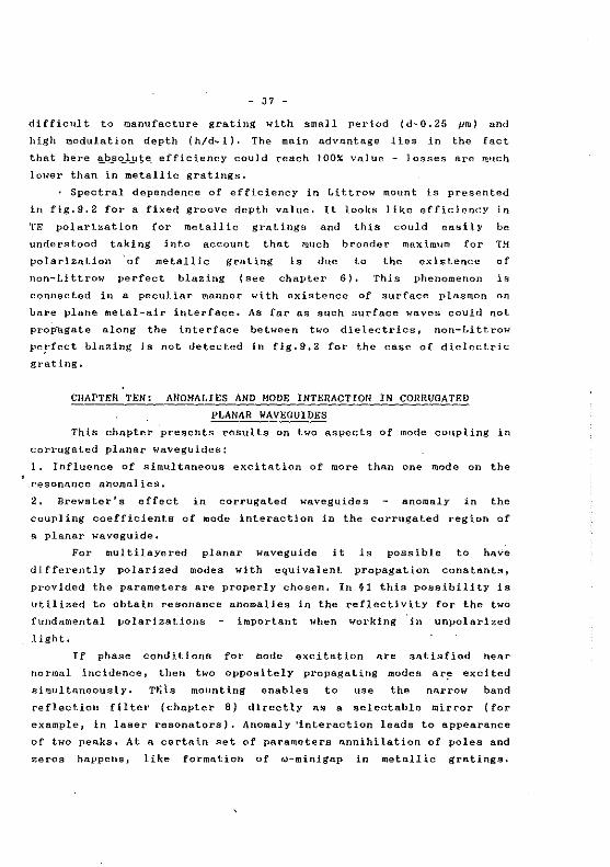
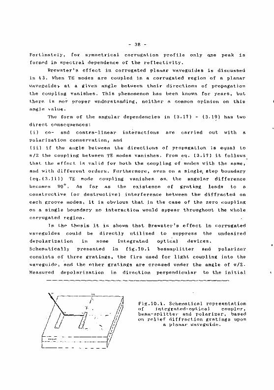
ln the thesis it is shawn thnt Brewster's effect in corrugated
.,..·nveguides could be direct! y ut il ized to suppress the undesired
depolarization
Schematically
in sorne
presented in
integrated optica.l deviees.
fig.lO.l beamsplitter and polarizer
consista of three gratings, the firs used for light coupling into the
waveguide, and the other gratings are croased under the angle. of n/2.
}lensured depolarizntion in dit·ection perpendiculnr to the initial
Fig,lQ.l. Schematical rept'e~>ntation
of integrated-optical coupler, beam-spl i tter nnd polnrizer, based on relief di {fraction gratings upon
a planar waveguide.
- 39 -
direction of propagation is lesa than 1~ only TE TH mode
conversion is observed 1 although mode propagation constants are almost
one and the same for the two polarization and phase conditions are
satisfied for excitation of bath modes.
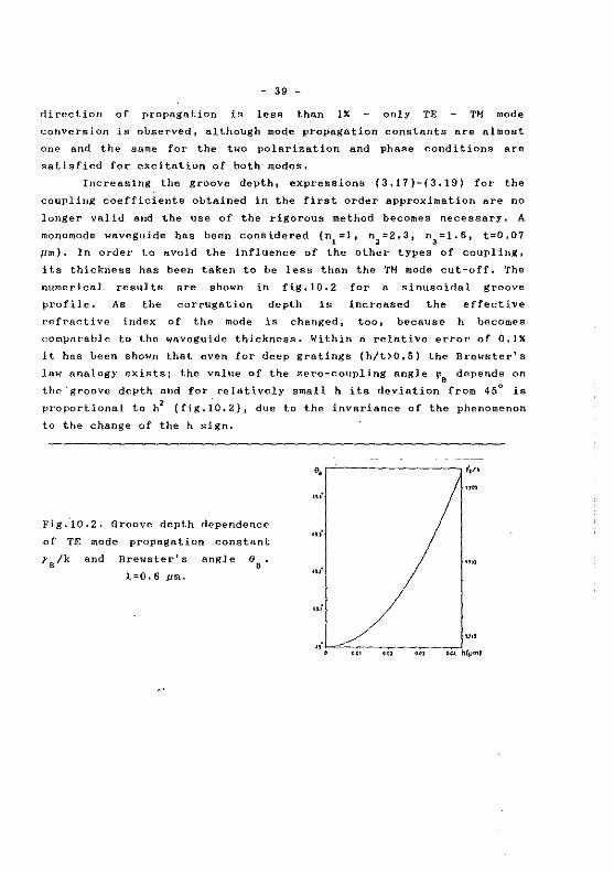
Increasing the groove depth, expressions (3,17)-(3.19) for the
coupling coefficients obtained in the first arder approximation are no
longer valid and the use of the rigorous method becornes necessary. A
rnonornode waveguide bas been considered (n1
=1, n2
=2.3, n3=1.6, t=0,07
jlm). In arder to avold the influence of the other types of coupling,
its thickness bas been taken to be less than the TH mode eut-off, The
numerical resulta are shawn in fig,l0.2 for a sinusoidal groove
profile. As the corrugation depth ls increased the effective
refracti ve index of the mode is changed 1 too, because h be cornes
comparable to the waveguide thickness. Within a relative error of O. lX
it has been shawn that even for deep gratings (h/t>0.5) the Brewster's
law analogy exista; the value of the zero-coupling angle ~8 depends on
the·groove depth and for relatively small h its deviation from 45° la
proportional to h 2 (fig.l0.2), due to the invariance of the phenomenon
to the change of the h sign,
Fig.10.2. Groove depth dependence
of TE mode propagation constant
r8 /k and Brewster' a angle 68
.
l.=O. 6 JI m.
""
•u·
...
""
- 40 -
CONCLUSION
The present thesis is devoted to theoretical and experimental
investigations on diffraction grating anomalies. Hain resulta of the
thesis could be grouped in the following directions:
I. Sorne new anomalies in diffraction efficiency of metallic and
dielectric relief gratings are predicted theoretically and confirmed
experimentally, as follows:
1. Resonance total absorption of light in deep metallic gratings
supporting a single propagating arder.
2. ·Non-resonance total absorption of lhtht by metallic gratings
,with two propagating orders.
3. 'Antiblazing' of metallic gratings - diffraction efficiency
of a deep metallic grating is almost zero in the entire angula.r
interval, provided it is zero in Littro~ mount.
4, Total deloca.lization of Bt1rface plasmon on corrugated
meta.f-a.ir interface when radiation (diffraction) !osses are high
then eigensolution of the system is not existing,
5. Resonance anomal y in the reflectivity of corrugated
waveguides,
6. 'Perfect blazing' for bare dielectric gratin_gs when light is
incident from the substrate side.
Sorne possibili-ties for utilization of these effects are discussed,
II. Connections are revealed that exist between these r\.ew anomalies
and already known on es 1 as well as between known but unidenti fied
anomalies { 'perfect blazing' in Littrow and nof!-Littrow mount and
Brewster's effect in shallow metallic gratings), Determination of such
connections enables to identify different anomalies, i.e. t.o link them
with (or to distinguish them definitely from) some phenomena on flat
surfaces (waveguide modes in optical waveguides- and surface plasmon
wave on metal-air interface).
III. Phy_sical reasons for appearance of anomalies _Jlre found in the
behavior of electromagnetic field characteristics in the vicinity of
grating sUrface and their influence on the far-field parameters. It is
shown that curls are formed in energy flow distribution . At a given
groove depth v~lue the lowest curls are t·otally hidden inside the
grooves and energy flow above the groove top is similar to the flow
above flat surface - quasi-periodicity of phases and efficiencies of
•
- 41 -
the propagating orders and of the diffraction losses of surface wave is induced.
The results presented in the thesis are published in the following papers: 1) L. L. Konstantinov, I. Z. Kostadinov and E. K. Popov: "Photoelectricity of AgI Under SubBandgap Illumination," Sol. St. Ionics 8, 127 (1983) 2) L. Mashev and E. Popov: "Diffraction efficiency anomalies of multilayer dielectric grating," Opt. Commun. 51, 131 (1984) 3) L. Mashev, S. Tonchev and E. Popov: "Two Dimensional Grating Beam Splitter and Polarizer," Bulg. J. Phys. 12, 297 (1985) 4) E. Popov and L. Mashev: "Dispersion Characteristics of Multilayered Waveguides," Opt. Commun. 52, 393 (1985) 5) L. Mashev and E. Popov: "Zero Order Anomaly of Dielectric Coated Grating," Opt. Commun. 55, 377 (1985) 6) E. Popov and L. Mashev: "Analysis of Mode Coupling in Planar Optical Waveguides," Opt. Acta 32, 265 (1985) 7) E. Popov and L. Mashev: "The Determination of Mode Coupling Coefficients," Opt. Acta 32, 635 (1985) 8) E. Popov and L. Mashev: "Convergence of Rayleigh Fourier Method and Rigorous Differential Method for Relief Diffraction Gratings," Opt. Acta 33, 593 (1986) 9) E. Popov, L. Mashev and D. Maystre: "Theoretical Study of the Anomalies of Coated Dielectric Gratings," Opt. Acta 33, 607 (1986) 10) E. Popov and L. Mashev: "Conical Diffraction Mounting: Generalization of a Rigorous Differential Method," J. Optics 17, 175 (1986) 11) E. Popov and L. Mashev: "Diffraction Anomalies of Coated Dielectric Gratings in Conical Diffraction Mounting," Opt. Commun. 59, 323 (1986) 12) E. Popov and L. Mashev: "Rigorous Electromagnetic Treatment of Planar Corrugated Waveguides," J. Opt. Commun. 7, 127 (1986) 13) G. A. Golubenko, A. S. Svakhin, V. A. Sychugov, A. V. Tischenko, E. Popov and L. Mashev: "Diffraction Characteristics of Planar Corrugated Waveguides," J. Opt. Quant. Electr. 18, 123 (1986) 14) E. Popov and L. Mashev: "Convergence of Rayleigh Fourier method and rigorous differential method for relief diffraction gratings nonsinusoidal profile," J. Mod. Opt. 34, 155 (1987) 15) L. Mashev and E. Popov: "Reflection gratings in conical diffraction mounting," J. Opt. (Paris) 18, 3 (1987) 16) E. Popov and L. Mashev: "Diffraction from planar corrugated waveguides at normal incidence," Opt. Commun. 61, 176 (1987) 17) L. Mashev and E. Popov: "Phenomenological approach to the resonance anomalies in relief diffraction gratings," Bulg. J. Phys. 14, 342 (1987) 18) L. Mashev and E. Popov: "Numerical Optimization of holographic diffraction grating efficiency," Bulg. J. Phys. 14, 549 (1987) 19) L. B. Mashev, E. K. Popov and E. G. Loewen: "Asymmetrical trapezoidal grating efficiency," Appl. Opt. 26, 2864 (1988) 20) L. B. Mashev, E. K. Popov and E. G. Loewen: "Total absorption of light by a sinusoidal grating near grazing incidence," Appl. Opt. 27, 152 (1988) 21) L. B. Mashev, E. K. Popov and E. G. Loewen: "Optimization of the grating efficiency in grazing incidence," Appl. Opt. 26, 4738 (1987)
- 42 -
22) E. Popov, L. Mashev and D. Maystre: "Backside diffraction by relief gratigs," Opt. Commun. 65, 97 (1988) 23) L. Mashev, E. Popov and D. Maystre: "'Antiblazing' effect in gratings," Opt. Commun. 67, 5, 321 (1988) 24) I. Savatinova, S. Tonchev, E. Popov and L. Mashev: "Electrically induced strip waveguide modes," Opt. Commun. 67, 4, 261 (1988) 25) E. Popov and L. Tsonev: "Electromagnetic field enhancement in deep metallic gratings," Opt. Commun. 69, 193 (1989) 26) E. Popov: "Total absorption of light in metallic gratings: a comparative analysis of spectral dependence for shallow and deep grooves," J. Mod. Opt. 36, 5, 669-674 (1989) 27) L. Mashev, E. Popov and E. Loewen: "Brewster effect for deep metallic gratings," Appl. Opt. 28, 2538-2541 (1989) 28) E. Popov, L. Mashev and E. Loewen: "Total absorption of light by metallic grating in grazing incidence a connection in the complex plane with other anomalies," Appl. Opt. 28, 5, 970-975 (1989) 29) L. Mashev and E. Popov: "Anomalies in metallic diffraction gratings," J. Opt. Soc. Am. 6, 10, 1561-1567 (1989) 30) E. Popov: "Plasmon interactions in metallic gratings: and k minigaps and their connection with poles and zeros," Surf. Sci. 222, 517-529 (1989) 31) E. Popov, L. Tsonev, and D. Maystre: "Gratings - general properties in Littrow mount and energy flow distribution," J. Mod. Opt. 37, 3, 367-377 (1990) 32) E. Popov, L. Tsonev, and D. Maystre: "Losses of plasmon surface wave on metallic grating," J. Mod. Opt. 37, 3, 379-387 (1990) 33) E. Popov and L. Tsonev: "Total absorption of light by metallic gratings and energy flow distribution," Surf. Sci. 230, 290-294 (1990) 34) E. Popov, L. Tsonev, E. Loewen and E. Alipieva: "Spectral behavior of anomalies in deep metallic gratings," J. Opt. Soc. Am. A 7, 1730-1735 (1990) 35) E. Loewen, E. Popov, L. Tsonev and J. Hoose: "Experimental study of local and integral efficiency behavior of a concave holographic diffraction grating," J. Opt. Soc. Am. A 7, 1764-1769 (1990) Patents: E. Popov and L. Mashev: "Method for selective reflectance," Bulgarian patent No 69561 36) L. Mashev, E. Popov, G. Zartov, R. Peeva and K. Panajotov: "Multilayered dielectric diffraction grating," Bulgarian patent No 64731
- 43 -
REFERENCES 1
1. R.Petit (ed, ): in Electromagnetic Theory of Gratings, (SpringerVerlng, Berlin, Heidelberg, New York), 1980, ch.!.
la.R.Petit(ed.}: Electromagnetic Theor:r of Gratinl!s (Springer Verlag, Berlin, Heidelberg, New York) 1980.
2. H.C.Hutley: DiffrB.ction Gratings (Academie Press, London, New York) 1982,
3. W,Werner: Appl.Opt.l6 1 2078 (1977), 4. M.Neviere 1 D.Haystre and W.R.J{unter: J.Opt.Soc.Am.68, 1106
(1978). 5. H.Neviere, P.Vincent and D.Haystre: Appl,Opt.17 1 843 (1978), 6. P.Vincent, H.Neviere and D.Haystre: Nucl,Instr.Heth.152, 123
(1978). 7, P.Vincent, H.Neviere and D.Haystre: Appl.Opt.18 1 1780 (1979), 8. G.H.Spencer and H.V.R,K.Hurty: J.Opt.Soc.Am.52, 672 (1962), 9, A.EopH H a,Bonb!fl! ÛCHOBbl oOTifi<H, HaYKa, 1973,
10. E.G,Loewen: Diffraction Gratings, Ruled and Holographie, in Appl.Opt. and Opt.Eng., vol.IX, ch.2.
11, P,Vincent and H.Neviere: Opt.Acta 26, 889 (1979), 12. R.Petit and D.Haystre: Rev.Phys.Appl.7 1 427 (1972). 13. D.Haystre and R,Petit: J.Spectr.Soc.Jpn.23, suppl., 61 (1974). 14, R.W.Wood: Phil.Hag,4, 396-402 (1902}, 15. V.Twersky: IRE Trans. Antennas Propagat. AP-4, 330-345 (1956), 16; V,Twersky: J.Res.Nat.Bur.Stand.64D, 715-730 (1960), 17. R.F~Hillar: Can.J.Phys,39, 81-103 (1961), · 18. R.F.Hillar: Can,J,Phys,39, 104-118 {1961). 19. H. Neviere: "The homogeneous problem" 1 Ch. 5
Theory of Gratings, ed. Petit ( Springer-Verlag, New York), 1980.
of Electromsgnetic Berlin, Heidelberg,
20. D.Haystre: "General study of grating anomalies fro·m electromagnetic surface modes", ch,l7 of Electromagnetic Surface Modes, ed. Boardman (Wiley 1 New York}, 1982.
21. Lord Rayleigh: Proc,Roy,Soc.(London) A79, 399 (1907). 22. Lord Rayleigh: Phil.Hag,6th ser.14, 60-65 (1907). 23, R.W.Wood: Phis.Rev 48, 928-936 (1935). 24. C,H.Palmer Jr.: J.Opt.Soc.Am.42 1 269-276 (1952), 25, J.E.Stewart and W,S,Gallaway: Appl.Opt.1, 421-429 {1962), 26. A.E.Siegman and P.H.Fauchet: IEEE J.Quant.Elactron. QE-22, 8,
1384-1402 ( 1986). 27. U.Fano: J,Opt.Soc.Am.31, 213-221 (1941). 28. A.Hessel and A.A.Oliner: Appl.Opt.4, 1275-1297 (1965), 29, A.Hessel and A.A.Oliner: Opt.Commun.59, 327-330 (1986), 30, D.Y.Tseng, A.Hessel and A.A.Oliner: U,R.S.J, Symposium on
Electromagnetic Waves, Alta Freq, 38 special issue, p.82-88 (1969). 31. A.Wirgin and R.Deleuil: J.Qpt.S6c.Am.59, 1348-1357 {1969). 32. H.A.Kalhor and A.R.Neureuther: J.Opt.Soc.Am.63, 1412 (1973). 33, A.Hessel, J.Schmoys and D.Y.Tseng:J.Opt.Soc.Am.65,380-384 (1975), 34. J,L.Roumiguieres 1 D.Haystre and R.Petit: J.Opt.Soc.Am.66, 8,
772-775 ( 1976). 35, D.Hay-stre, H.'éadilhac and J.Chandezon: Opt.Acta 28, 457 {1981). 36, D,Hay-stre and M.Cadilhac: Radio Sci.l6 1 6, 1003-1008 (1981), 37, H.Breidne and D.Haystre: Proc, SPlE Periodic Structures,
Remark: This is a list of ali the refernces cited in the thesis, but not only in the summary.
- 44 -
Gratings, Haire Patterns and Diffraction Phenomena vol.240 1 165, (1980). 38. D.Haystre "and R.Petit: Opt.Commun.17, 196-200 (1976), 39. H.C.Hutley and D.Haystre: Opt,Commun.19 431 (1976). 40, A.A.Haradudin and A.Wirgin: Surf.Sci.162, 980-984 (1985). 40a.A.IHrgin and A.A.Haradudin: ·Progress Surf.Sci.22 1 1, 1:-99 (1986), 41. A.A.Haradudin: Proc.ISCHP(Varna'BO, Bulgaria}, 1, 11-399 {1981), 42. T.Tamir (ed. ): Integrated Optics (Springer, Berlin), 1975. 43. A. W. Snyder and J. D. Love: Optical Waveguide Theory ( Chapman and
Hall, London), 1983. 44. H.Kogelnik: in Integrat_ed Optics 1 Springer 1 1975 1 ed.T.Tamir 1
ch.2. 45. D.Harcuse: Theory of Dielectric Optical Waveguides (Academie, New
York), 1975. 46. E.Popov and L.Hashev: Opt.Commun.59, 323 (1986), 47, A,Yariv: IEEE J.Quant.Electron.QE-9, 919 (1973). 48. E.Popov and L,Hashev: J,Opt.Commun.7 1 127 (1986), 49. E.Popov and L.Hash~v: Opt.Commun.61, 176 (1987). 50. D.Maystre: in Progress in Optics ~~I, ed.E.Wolf, Elsevier, 1984,
ch.l. 51. R.Petit: Rev.Opt.42, 263 {i963). 52, R.Petit: Rev.Opt.45 1 249 (1966), 53; W.C.Heecham: J.Appl.Phys.27 1 361 (1956), 54. -H.Ikino and K.Yasuura: IEEE Trans.Antennas Propag.AP-21, 657
( 1973). 55. R.F.Hillar: Radio Sci.8, 785 (1973), 56, H.Ikino and K.Yasuura: IEEE Trans.Antennas Propag.AP-24, 884
(1976), 57. H.Cadilhac: in Electromagnetic Theory of Gratings, Springer,
1980, ed.R.Petit, ch.2, 58, J.P.Hug~nin, R.Petit and H.Cadilhac: J,Qpt.Soc.Am.71, 5, 593
(1981). 59. R.Petit and H.Cadilhac: C.R.Acad.Sci.262, 468 {1966), 60, R.F.Hillaf.: Proc.Cambridge Philos.Soc.69, 175 (1971). 61. R.F.Hillar: Proc.Cambridge Philos.Soc.69, 217 (1971). 62. H.Neviere and M.Cadilhac: Opt.Commun.2 1 235 (1970), ' 63. P.H.Van den Berg and J.T.Fokkema: J.Opt.Soc.Am.69, 27 (19.79). 64, A.Wirgin: C.R.Acad.Sci.B288, 179 (1979). 65. A.Wirgin: C.R.Acad.Sci.B289, 273 (1979), 66. A.Wirgin: C.R.Acad.Sci.A289, 259 (1979), 67. A.Wirgin: Opt.Acta 27, 1671 (1980). 68. A. Wirgin: Opt.Acta 28, 1377 {1981). 69. D.Agassi and T.George: Phys.Rev.B33, 2393 (1986), 70. P.H.Van den Berg: J.Opt.Soc Am.71, 1224 (1981_) •
. 71. R.Petit and H.Cadilhac: C.R.Acad.Sci.259 1 2077 (1964), 72. A.Wirgin: Rev.Opt.9, 499 (1964}. 73. J.L.Uretsky: Ann.Phys.33, 400 (1965). 74. J.Pavageatl 1 R.Eido and H,Kobeisse: C,R,Acad.Sci._?64 1 424 (1967). 75. A.Wirgin: Rev.Cethedec 5, 131 (1968), 76. A.Neureuther and K.Zaki: Alta Freq,38, 282 (1969),
.77, P:H.Van den Berg: Appl.Sci.Res.24i 261 (1971). 78. G.Dumery and P.Filippi: C.R.Acad.Sci.270, 137 (1970), 79. D.Maystre: in Electromsgnetic Theory of Grstings, Springer, 1980,
ed.R.Petit, ch.3. 80. D.Haystre: ·apt.Commun.6, 50 (1972), 81, D.Haystre: Opt.Commun.8, 216 (1973), 82. ·D;Haystre: J.Opt.Soc,Am.68, 490 (1978).
- 45 -
83. D.Haystre: Opt.Commun,26 1 127 {1978). 84. L.C.Botten: Opt.Acta 25, 481 {1978), 85. L.C.Botten: J,Qpt.11, 161 (1980), 86. P. Vincent~ in Electromagnetic Theory of Gratings, Springer, 1980,
ed.R,Petit, ch.4. ' 87. H.K.Hoaveni, JI,A.Kalhor and A.Afrashten: Comput.and Electr.Eng.2,
266 !1975);. 88, R.Petit~ Rev,Opt,45, 353 (1966), 89, H,Neviere, P.Vincent and R.Petit: Nouv.Rev.Opt.5, 65 (1974). 90. K,C,Chang,V.Shan.and T.Tamir: J.Opt.Soc.Am.70, 804 (1980). 91. H.G.Moharam and T;K.Gaylord: J.Opt.Soc.Am.72, 1385 (1982). 92. T.K.Gaylord and H.Q.Hoharam: Proc,IEEE 73, 894 (1985). 93. H.Neviere, G,Cerutti-Haori and H.Cadilhac: Opt.Commun.3, 48
( !971). 94, J,Chandezon, D.Haystre and G.Raoult: J,Opt.ll, 235 {1980). 95, J.Chandezon, H.Dupuis, G,Corhet and D.Haystre: J.Opt.Soc.Am.72,
839 (1981). 96. E.Popov and L.Hashev: J.Optics 17, 175 (1986) 97}• W, S. Do rn and HcCracken: Numerical Hetods wi th FORTRAN VI case
studies, Wiley, New York, 1972. ,98, B,N,Parlett: The Symmetric Eigenvalue Problem, Prentice-Hall, 1980,
99. E.Popov and L.Hashev: Opt.Acta 33, 593 (1986), 100. E.Popov and L.Hashev: J,Hod.Opt.34, 155 (1987), 101. K.Wagatsuma, H.Sakaki and S.Saito~ IEEE J.Quant.Electr.QE-15, 632 (1979). 102. A.W.Snyder: J.Opt.Soc.Am.62, 1267 (1972). 103. K.K.Swidzinskij: Kwant.Elektr.7, 1914 (1980), 104. D.Maystre and H.Neviere: J,Optics 8, 165 (1977). 105. S.T.Peng, T.Tamir, H.L.Bertoni: IEEE Trans.MTT, HTT-23, 123 (1975). 106. D.G.Hall: Opt.Lett.S, 315 (1980), 107, S.T,Peng and A.A.Oliner: IEEE Trans.HTT, HTT-29 1 843 (1981), 108, S.T,Peng and A.A.01iner: IEEE Trans.HTT, MTT-29 1 855 (1981), 109. E,Popov and L.Hashev: Opt,Acta 32, 265 (1985). 110. E.Popov and L.Hashev: Opt,Acta 32, 635 (1985), 111. E.Popov and L.Hashev: Opt,Commun.52, 393 (1985), 112. A,Yariv and H.Nakamura: IEEE J,Quant.Electr.QE-13, 233 (1977), 113. K.Yasumoto and H.Hurayama: Technical Report CSCE-86-A02, Fukuoka, Japan ( 1986). 114. G.I.Stegeman, D,sarid, J,J,Burke and D.G.Hall: J,Opt.Soc.Am.71, 1497 (1981). 115. E.Popov, L.Tsonev 1 and D.Maystre: J,Hod.Opt.37, 379 (1990). 116, E.Popov, L.Tsonev, and D.Maystre: J,Hod.Opt.37, 367 (1990), 117. J.V.Hajnal: Proc,R.Soc.Lond,A414, 447-468 {1987), 118. E.Popov, L.Hashev and D.Maystre: Opt.Acta 33 1 607 (1986), 119. J.R.Andrewartha, J,R.Fox: and I.J,Wilson: Opt.Acta 26, 1 1 69-89 (1979). 120. J.R.Andrewartha, J,R,Fox and I.J.Wilson: Opt.Acta 26, 2, 197-209 (1979). . 121. E.Popov, L.Has.hev and E.Loewen: Appl.Opt.28, 970 (1989), 122. D.Haystre and H.Neviere: J,Opt.B, 165 (1977), 123. D.Haystre, H,Neviere, R.Reinisch and J,L,Coutaz: J,Qpt.Soc, Amer.B5 338 (1988), 124. H.Neviere and R.Reinish: J.Phys,(Paris) 44 1 suppl.12 1 Cl0-359 (1983). 125. R. Reinisch, G. Chartier, H .Neviere, M. C. Hutley, G. Claus a,
- 46 -
J.P.Galaup and J.F.Eloy, J,de Physique-Lett.44 Ll007 (1983,). 126. J.L,Coutaz: J.Opt.Soc,Amer.B4, 105 (1987), 127. H.Neviere, H.Akhouayri, P.Vincent and R.Reinisch: Proc. Soc, Photo-Opt. Instrum, Eng. 815 1 146 (1987), 128. J.L.Coutaz and R.Reinisch: Solid St.Commun.56, 545 (1985). 129. K.Hetcalfe and R.Hester: Chem.Phys.Lett:94, 411 (1983). 130, M.Y~mashita and H.Tsuji: J,Phys.Soc.Jap.52 2462 (1983), 131. R.Renisch and M. Neviere: Opt,Engng.20 1 629 (1981), 132. L.Hashev, E.Popov and E.Loewen: Appl.Opt.28, 2538-2541 (1989), 133. E.Popov and L.Tsonev: Surf,Sci., to be published. 134. E.Popov and L.Tsonev: Opt.Commun.69, 193 (1989), 135, L.Hashev: Relief holographie diffraction gratings, PhD thesis, Sofia, 1985, 136, L.Hashev 137, L.Hashev 138. B.Racz 1
( 1981).
and s.Tonchev: Appl.Phys.A26, 143 and E.Popov: J.Opt.l8, 3 (1987), Zs.Bor, S.Szatmari and Q,Szabo:
(1981).
Opt.Commun.366, 399
139, L.B.Mashev 1 E.K.Popov and E.G.Loewen: Appl.Opt.26, 4738 {1987), 140. L.Hashev 1 E.Popov and E.Loewen: Appl.Opt.27 1 152 (1988), 141, L.Hashev, E.Popov and D.Haystre: Opt.Commun.67, 321 (1988). 142. E.Popov, L.Tsonev; E.Loewen, and E.Alipieva:. J.Opt,Soc.Am., to be. published. 143, F.Toigo, A.Harvin, V.Celli and N.R.Hills: Phys.Rev.B15, 5618 ( 197 7 ) • 144. N.E,Glass, H.G.Weber and D.L.Hills: Phy,s.Rev.B29 1 -6548 (1984). 145. D.Heitmann, N.Kroo, Ch.Schulz and zs.Szentirmay: Phys.Rev.B35, 2660 ( 1987). 146. II.Jonsson, J,H,Weare, T.H.Ellis and G.Scoles: Surf.Sci.180, 353 ( 1987). 147. P.Tran, V,Celli and A.A.Hsradudin: Opt.Lett.13, 530 {1988). 148. E.Popov: Surf,Sci.222, 517 (1989), 149. I.A.Avrutskii, G,A.Golubenko, V,A.Sychugov, and A.V.Tischenko: K1~ant.Elektr.13, 1629 (1986). 150. E.Popov: J.Mod,Opt,36 1 669 (1989). 151. L.Mashev and E.Popov: J.Opt.Soc.Am.6, 10 1 1561-1567 (1989), 152. L.Hashev and E.Popov: Opt,Commun.55, 377 (1985), 153, G.Haas and R.E.Thun (eds, ): Physics of Thin Films, Advances in Research and Development, vol.2, ch.6 1 (Academie Press, New York and London) 1 1964. 154, L.Hashev and E.Popov: Opt.Commun.51, 131 (1984), 155. G.A.Golubenko, A.S.Svakhin, V.A.Sychugov, A.V.Tischenko 1 E.Popov and L.Hashev: J,Opt.Quant.Electr.18 1 123 {1986), 156. E.Popov, L.Hashev and D.Haystre: Opt.Commun.65, 97 (1988), 157, E.Popov and L,Tsonev: unpublished. 158, R.C.Enger and s.K.Case: J.Opt,Soc.Am.73 1 1113 (1983). 159, K.Yokomori: Appl.Opt.23, 2303 {1984). 160. P. Y eh: Optical wa\•es in laye red media, Wiley series in Pure and Applied Optics {Wiley, New York), 1988. 161. I.A.Avrutskii, V.P.Duraev, E.T.Nedelin, A.M.Prohorov, A.S.Svakhin, V.A.Sychugov and V.A.Tisschenko: K\~ant.Elektr,15, 569 (1988). 162. W.A.Sychugow, A.W.Tishchenko ( 1979).
A.A.Hakimo\.'! Pisma JTF 5.
163. L.Hashev 1 S.Tonchev 164, G.Korn and T.Korn:
and F.,Popov: Bulg.J.Phys.l2, 297 !1985), Hathematical llandbook ( HcGra.w-H i 11 Book
New York), 1968.
937
Co,


![[PPT]Diffraction gratings - Welcome | Biomedical Optics …bol.egr.uh.edu/.../bol/files/files/Diffraction_gratings.ppt · Web viewDiffraction gratings By M. Ravi Kiran Introduction](https://img.pdfslide.net/doc/110x75/5ac864db7f8b9a6b578c1399/pptdiffraction-gratings-welcome-biomedical-optics-bolegruhedubolfilesfilesdiffraction.jpg)