Embed Size (px)
Citation preview
ANSI/APCO Public Safety Grade Site Hardening Requirements
APCO ANS 2.106.1-2019
2
Copyright ©2019 APCO International | All Rights Reserved
TABLE OF CONTENTS
ACKNOWLEDGMENTS .......................................................................................................................................................... 3
FOREWORD ......................................................................................................................................................................... 5
EXECUTIVE SUMMARY ......................................................................................................................................................... 6
ENVIRONMENTAL EVENTS ................................................................................................................................................... 8
2.1 SEISMIC EVENTS .............................................................................................................................................................. 8
2.2 LAND WILDFIRES ........................................................................................................................................................... 10
2.3 FLOODING ................................................................................................................................................................... 12
2.4 WIND EVENTS .............................................................................................................................................................. 14
2.5 ICE STORMS ................................................................................................................................................................. 16
2.6 GRID FAILURES ............................................................................................................................................................. 18
2.7 GEOGRAPHICAL SPECIFIC EVENTS ..................................................................................................................................... 19
2.8 OVERRIDING PERSONNEL CONSIDERATIONS ........................................................................................................................ 20
PUBLIC SAFETY GRADE SITE REQUIREMENTS ..................................................................................................................... 21
3.1 GENERAL REQUIREMENTS ............................................................................................................................................... 21
3.2 PHYSICAL SECURITIES ..................................................................................................................................................... 22
3.3 ANTENNA SUPPORT STRUCTURE ....................................................................................................................................... 34
3.4 LIGHTNING PROTECTION AND GROUNDING ........................................................................................................................ 36
3.5 EQUIPMENT ENCLOSURES ............................................................................................................................................... 39
3.6 ENVIRONMENTAL AND CLIMATE CONTROL ......................................................................................................................... 41
3.7 POWER ....................................................................................................................................................................... 41
APPENDIX A: ...................................................................................................................................................................... 57
EXISTING SITE HARDENING STANDARDS............................................................................................................................ 57
ACRONYMS AND ABBREVIATIONS ..................................................................................................................................... 58
NOTES ............................................................................................................................................................................... 59
APCO AMERICAN NATIONAL STANDARDS ........................................................................................................................................... 60
3
Copyright ©2019 APCO International | All Rights Reserved
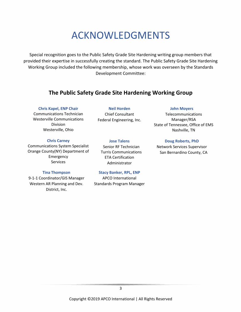
ACKNOWLEDGMENTS
Special recognition goes to the Public Safety Grade Site Hardening writing group members that
provided their expertise in successfully creating the standard. The Public Safety Grade Site Hardening
Working Group included the following membership, whose work was overseen by the Standards
Development Committee:
The Public Safety Grade Site Hardening Working Group
Chris Kapel, ENP Chair Communications Technician Westerville Communications
Division Westerville, Ohio
Neil Horden
Chief Consultant
Federal Engineering, Inc.
John Moyers
Telecommunications Manager/RSA
State of Tennessee, Office of EMS Nashville, TN
Chris Carney
Communications System Specialist Orange County(NY) Department of
Emergency Services
Jose Talens
Senior RF Technician Turris Communications
ETA Certification
Administrator
Doug Roberts, PhD
Network Services Supervisor
San Bernardino County, CA
Tina Thompson
9-1-1 Coordinator/GIS Manager
Western AR Planning and Dev.
District, Inc.
Stacy Banker, RPL, ENP
APCO International
Standards Program Manager

4
Copyright ©2019 APCO International | All Rights Reserved
APCO Standards Development Committee
Daniel Morelos Tucson Airport Authority
Arizona
Karen Allen SRP Security Services
Phoenix, Arizona
Sherry Taylor Indianapolis Fire Department
Communications Division, Indiana
Bradford S. Smith Framingham Fire Department
Massachusetts
Judith Weshinskey-Price Pinellas County Regional 9-1-1
Largo, Florida
Bud Hicks, ENP Grundy County 911
Morris, Illinois
Rick Thomas, RPL Apex, North Carolina
Kim Ostin
Sterling Heights Police Dept. (Ret) Sterling Heights, MI
Stephen Ashurkoff, ENP
General Dynamics IT
Stacy Banker, RPL, ENP Standards Program Manager
APCO International
Jackie Pace Redwood City, California
Nathan McClure, ENP
Past APCO International President AECOM, Retired
Stephen Devine
FirstNet
James Leyerle, ENP OnStar, Retired
Nicola Tidey, RPL, ENP
Mission Critical Partners College Station, Pennsylvania
Monica Lynn DELTAWRX
Woodland Hills, California

5
Copyright ©2019 APCO International | All Rights Reserved
FOREWORD
ISBN: 978-1-943877-30-0
©2017; all rights reserved
APCO International
351 N. Williamson Blvd. Daytona Beach, FL 32114
APCO International is the world's largest organization of public safety communications
professionals. It serves the needs of public safety communications practitioners worldwide, and the
welfare of the public, by providing complete expertise, professional development, technical
assistance, advocacy, and outreach.
The 2018-2019 APCO International Executive Board:
Holly Wayt, President
Tracey Hilburn, First Vice President
Margie Moulin, Second Vice President
Martha Carter, Immediate Past President
Derek Poarch, Ex-Officio
APCO International standards are developed by APCO committees, projects, task forces, writing
groups, and collaborative efforts with other organizations coordinated through the APCO
International Standards Development Committee (SDC). Members of the committees are not
necessarily members of APCO. Members of the SDC are not required to be APCO members. All
members of APCO's committees, projects, and task forces are subject matter experts who volunteer
and are not compensated by APCO. APCO standards activities are supported by the Communications
Center & 9-1-1 Services Department of APCO International.
For more information regarding APCO International and APCO standards please visit:
www.apcointl.org
https://www.apcointl.org/standards.html
6
Copyright ©2019 APCO International | All Rights Reserved
Chapter 1
EXECUTIVE SUMMARY This standard is a comprehensive analysis of site hardening requirements and was compiled by the Association of Public Safety Communications Officials (APCO) International. The American National Standards Institute (ANSI) approved this standard on June 11, 2019. The original APCO Report, created by the Broadband Committee, has been edited here to match the formatting of the National Public Safety Telecommunications Council (NPSTC) report. This work represents site requirements with the specific future intention to establish “hardening” standards, which create public safety grade sites. The requirements in this document have been developed by a subcommittee of the APCO Broadband Committee representing government communications system operators, communications systems vendors, representatives from commercial service provider Land Mobile Radio (LMR) professionals, and broadband industry consultants.
This standard represents public safety requirements regarding various characteristics to make mission critical communications network sites sufficiently robust to meet the service availability requirements of public safety. In other words, what it takes to make network sites “public safety grade” or the extent to which they are “hardened.” The document is intended to assist public safety communications network builders with the guidelines necessary to build hardened public safety grade networks. This document addresses hardening for wireless transmission and reception sites. Specifically, it addresses the hardening requirements to provide the appropriate site conditions and characteristics for wireless system electronics (e.g., transmitters and receivers) and wireless passive components (e.g., coaxial cables and antennas). These sites need to withstand the onslaught of natural or manmade conditions and consider the distinct requirements for different geographic locations of the United States, including their likelihood to be subject to severe storms, earthquakes, tornadoes, and other disasters.
For the purposes of this document, wireless transmission and reception sites shall be defined as the location where fixed base station, transmitter, or receiver equipment is installed for any of the FCC services used by, or in support of, Public Safety agencies. This includes the Land Mobile Radio (LMR) Service, cellular communications service, 700 MHz Service, Advanced Wireless Service (AWS), Broadband Personal Communications Service (PCS), Specialized Mobile Radio (SMR) Service and/or Nationwide Public Safety Broadband Network (NPSBN). Wireless transmission and reception sites include facilities without a shelter structure utilizing ground/slab or tower mounted equipment, facilities including a shelter structure specifically designed to house transmitter or receiver equipment (typically unoccupied), or facilities where equipment is located within a shelter and structure co-located with occupied space, whether such space is communications related such as a dispatch center or PSAP, or space partly or wholly used for other than communications related activities. To the greatest extent practical, the term “wireless transmission and reception site” refers only the portions of a shared shelter/structure that house the base station, transmitter, or receiver equipment.
For the purposes of this standard, a site is made up of many pieces of equipment that should include,
but are not limited to:
7
Copyright ©2019 APCO International | All Rights Reserved
Wireless network equipment: transmitters, receivers, and associated electronics
System interconnection and/or backhaul network equipment: microwave transmitters, receivers,
associated electronics, optical fiber equipment, and other equipment, or systems providing
similar functionality.
Wireless Network (non-transmission or reception) equipment - wireless network computing and
control equipment. Examples of this include network routers, network switches, database and
applications servers, and other system electronics (often referred to as system core equipment).
Equipment enclosure - a structure used to house communications equipment (examples would
be buildings, equipment shelters, or outdoor cabinets).
Environmental support - environmental control systems to include heating and cooling of the
equipment enclosure.
Commercial and redundant power systems
Antenna structures - structures to support communications site apparatus above the ground.
This includes mounts, and all associated hardware included as well as feed lines.
Antennas, mounts and all associated hardware are included.
Physical security - fences, walls, or other means to protect the site to ensure that the resource
remains operational and functioning.
The high cost associated with meeting these requirements may not be feasible at all sites. The parties
shall consider the importance of the site, be it a site that aggregates substantial traffic or the criticality
of a facility it serves, against the cost to achieve these requirements. In some cases, sites lack the space
or other constraints to meet some of these requirements at any cost. At the same time, the risk of failure
shall also be assessed for the site. For example, if the risk is high that commercial power will fail, backup
power sources become more critical and worth the investment. Power failures represent one of the
most common causes for outage in communication networks. Therefore, redundant power solutions are
a critical element in achieving Public Safety Grade (PSG) system availability. This underscores the need
to assess the cost of each requirement against risk and the likelihood of that risk. It is important to note
that the risk factors shall address not only the likelihood of an event that causes unavailable
communications, it shall also address the impact of lack of communications. When a risk factor protects
against ice storms, it shall also assess the impact of loss of public safety communication in dealing with
the ice storm.
In summary, what you will find in this document is a practical and feasible source of information that
you can use at current and future site locations. This resource was developed and vetted by industry
leading professionals that fully understand what it takes to make your site locations resilient enough to
keep networks functioning under some of the more trying circumstances.
8
Copyright ©2019 APCO International | All Rights Reserved
Chapter Two
ENVIRONMENTAL EVENTS
SCOPE Environmental events shall be considered during the design, construction, and ongoing operations of a
PSG system. There are many variations that shall be addressed to ensure that the system can withstand
situations that may be local or regional in nature. Depending on their location, some facilities and sites
shall guard against flooding and earthquakes but not against freezing ice storms. Other areas might
require protection from tornado force winds. Each geographic area should be considered unique.
Environmental risk factors are grouped into seven specific “force of nature” threat categories that may
compromise the sustainability of a mission critical communications network. The following section
identifies and explains the risk factors, analyzes the nature of the risk, and provides recommendations
to manage the risk. The section is organized by threat type, including the impact to communication sites
as well as recommendations to protect against each event. These recommendations are captured as best
practices in the requirements section that follows. It should be noted that lightning protection is covered
in this document.
Animals may also cause problems that disrupt critical infrastructure. Care should be given to protect
facilities and infrastructure against this potential cause of damage.
2.1 Seismic Events
Seismic events include earthquakes and related events, including mudslides and landslides
caused by natural or manmade circumstances.
2.1.1 Seismic Events Analysis
Historically, the risk of earthquakes has been tied to geographical areas, typically
California. In the last few years, earthquakes have also struck and impacted other areas of
the country, well beyond California. Not all earthquakes are created the same. Much of
the damage potential from earthquakes to communication network facilities and
equipment can be gauged by the type of soil the network installation rests on. Soil
compaction may positively or negatively affect how a facility and equipment “rides out”
the event.
Ground shaking is the most common hazard of earthquakes. Violent shaking, along with
asymmetrical settling of soil beneath a communication structure, can cause an otherwise
sturdy structure to be damaged or destroyed. Buildings or radio towers located near a
fault are subject to the effects of ground displacement. Ground displacement occurs when
9
Copyright ©2019 APCO International | All Rights Reserved
soil “tears” causing the ground to move in a different direction on either side of the fault.
Buildings or towers built upon a fault can easily be destroyed during a seismic event. The
San Andreas Fault Line, which runs through a large part of California, and the New Madrid
Fault Line which bisects the states of Illinois, Indiana, Missouri, Arkansas, Kentucky, and
Mississippi, are both capable of producing significant magnitude earthquakes and ground
displacement.
In recent times, a threat similar to earthquakes, but much more localized has been
experienced in the southeast portion of the country. Sinkholes, or areas where unstable
land had depressed or shifted in some way, would be a network threat both to buildings,
towers, and utility connections. Sinkholes are a specific example of a greater phenomenon
known as soil liquefaction. Soil liquefaction occurs when previously stable soil becomes
fluid, often because of vibrations caused by earthquakes. The risk of liquefaction is more
probable on sandy type soil which resides over a high-water table. Soil liquefaction may
be correlated because of an earthquake but there are also examples of liquefaction
occurring outside of a seismic event.
Virtually every major earthquake includes liquefaction. Earthen dams and buildings built
over reclaimed land would be at a higher risk for damage or destruction resulting from
liquefaction.
2.1.2 Seismic Event Recommendations
The potential for network damage, destruction, or interruption resulting from earth
movement can be managed, and thus the site hardened through a two-part process. First,
a network designer should evaluate the site location and quantify the overall risk of an
earthquake or soil liquefaction at that location, along with understanding the potential
intensity of land movement that may be encountered during an event. Resources to
complete this analysis include United States Geological Survey (USGS) seismic charts, soil
composition, and stability studies, along with an understanding of prior land uses at that
site. The second part of the process is to employ facility construction and equipment
installation processes that will allow the network installation some level of resiliency
against the potential damage of seismic motion. These measures may state upsizing of
structural members that are subject to shearing forces, the use of base isolation
techniques, or a minor adjustment in site location to take advantage of more stable soil.
Typically, local building codes in areas with a high likelihood of seismic activity will require
protection against earthquakes. However, historical events have shown that areas
outside the active seismic areas are also susceptible and should be considered.
10
Copyright ©2019 APCO International | All Rights Reserved
2.2 Land Wildfires
Land Wildfires are those that typically burn in remote areas with forested or grassy regions. These
fires are typically fast moving and may be fed by high winds which can disrupt electric
transmission lines.
2.2.1 Land Wildfires Analysis
Land Wildfires happen not only in forest areas but also in the urban interface transition
areas. Urban interface areas form the boundaries between the primitive forests and more
developed or improved populated areas. Wild land fires represent a threat to site
equipment buildings, outdoor equipment cabinets, and, to a degree, radio towers. While
it stands to reason that network components in direct contact with flames is a major
threat to network survivability, the indirect heat transfers from a closely burning fire is
equally hazardous to network survivability. Land Wildfires frequently are fast moving,
very hot, and will burn anything that is made of combustible materials. An example of
heat damage is from the 2003 Old Fire in the San Bernardino National Forest- an
automobile caught in the fire had the aluminum engine block completely melted. In the
same fire, LMR site buildings with wood frame roof and composite roofing shingles had
the entire roof burned causing damage to the equipment housed inside in addition to the
building itself. A few years later, during a wild land fire in 2009 burning in Los Angeles
County, a public safety site burned because it had an older building made of combustible
material. The building had been covered in foam with a fire barrier but winter ice damage
had exposed the wood in the building’s roof. This allowed embers to gather and collect,
and then ignite the rooftop and burn the building sometime after the fire had passed by.
Wild land fires can pose a serious risk to communications sites and to outdoor equipment
not housed in shelters. Communications buildings and shelters provide an extra layer of
protection, in some cases sacrificial, to prevent damage from direct fire impingement or
radiant heat transfer.
Terrain can also play a large role in influencing the damage potential of a wild land fire.
Site installations at the top of a canyon—especially in line with the canyon floor—will be
subject to some of the greatest heating potential as a fire progresses up a canyon from a
lower elevation. This heat can actually melt radio tower feed lines and antenna systems.
Prevailing winds can also influence a wild land fire’s direction of travel. Lastly the
concentration of vegetation and its proximity to a communications site is also a factor
that can place a network at risk.
2.2.2 Land Wildfires Recommendations
The threat of a wild land fire can be managed through a combination of calculated siting,
the utilization of fire resistive construction materials and techniques. The Agency Having
11
Copyright ©2019 APCO International | All Rights Reserved
Jurisdiction (AHJ) should develop and implement a plan for proactive site area
maintenance, which will provide crucial for the affected areas. Site locations should be
chosen with respect for natural fire behavior in each area. The AHJ should consult with
fire protection experts with a localized knowledge base to analyze and rank the relative
fire safety of a location. AHJs should avoid site options where heat is focused or burning
debris is more likely. AHJs should consider more desirable site locations that include
options with easy vehicular ingress and egress, are close to fire roads and nearby water
supply. Firefighters triage areas that are within or threatened by a burning wildfire, and
will favor protecting buildings and structures that offer the maximum return on their
firefighting efforts while minimizing the risk to their personal safety.
Site structures should be constructed with an emphasis on their resistivity to damage
from direct and indirect heating. Buildings constructed in areas with a high likelihood for
wild land fire threats shall be constructed using non-combustible and self-extinguishing
materials to provide maximum protection from heat. Techniques or protective measures
should be considered and employed to prevent the fire from “extending” into the building
on combustible cabling or antenna feed line jackets or sheathing. Architectural features
that will better shield the building from the collection of heat and embers should be a
high priority in development. Steel towers, while likely able to survive heating, play host
to rather fragile network appliances such as antennas or microwave dishes, feed lines,
and sometimes outdoor radio equipment that is attached to the tower. Plumes of radiant
heat or blowing embers can easily melt items and equipment on towers, rendering them
useless at the onset of fire encroachment. Any active radio equipment mounted on tower
structures or antennae support structures should be protected from heat damage from a
fire that burns over the installation.
Equipment housed in outside cabinets shall be protected from heat to minimize damage
if the cabinet and site are burned over. Only metal non-combustible tower structures
should be used. Wooden poles should not be used for a mission critical installation.
A routine schedule of preventative site maintenance should be developed and kept as a
high priority in site operation. Site maintenance tactics can begin with pre-emergent
weed and brush control. Scheduled brush clearance and removal of debris from the site
should occur at regular intervals. A periodic inspection of building safety features should
also be on a site maintenance schedule. While local regulation may differ, a basic standard
is to remove and haul away combustible materials for a minimum distance of 30 feet
around a structure. Reducing fuel from 30 to100 feet away from the structure provides
additional protection during a wildfire (NFPA 1144 Wildfire Checklist). These practices
lead to a communications installation that is highly defendable during a wild land fire
threat.
12
Copyright ©2019 APCO International | All Rights Reserved
2.3 Flooding
Flooding stems from unwanted or uncontrolled water intrusion caused by natural or manmade
events that create a barrier to sustained network operations.
2.3.1 Flooding Analysis
Floods are caused when more water flows through the hydrological system than can be
absorbed or drawn off through natural process including absorption and evaporation. The
hydrological system is the continuous cycle of evaporation of the ocean waters that create
rain and eventual drainage back into the ocean.
Quantities of rain exceeding more than 1 inch per hour will begin to cause pooling of
water, which may eventually lead to flooding. Flooding is categorized into five different
types, generally correlating to where the flood is physically occurring. The types of
flooding are (1) flash floods, (2) coastal floods, (3) urban floods, (4) river floods, (5)
ponding. Flash floods are terrain driven and would be prevalent in areas of steep slopes
that rapidly concentrate and funnel water and debris along a natural drainage path.
Coastal floods occur when the sea, typically from a hurricane’s storm surge, distributes
the water inland, beyond the typical shoreline. Urban floods occur in developed areas,
resulting from natural causes such as poor drainage after a heavy rain or from manmade
circumstances such as a damaged water main or a failed water pumping or draining
system. River floods occur when rivers or lakes overflow their boundaries and flood the
surrounding area. Finally, ponding floods result from extended rainfall over relatively flat
land that cannot dissipate the water fast enough. This type of flooding is limited to very
shallow water depths, such as an inch or so.
Flooding can interrupt service from a communications facility from the obvious effect of
water inundation that causes equipment malfunction or destruction, to less obvious
causes such a power grid or fiber transport systems interruption caused by flooded
conduits and switch boxes. In severe floods, buildings can be washed away by the force
and speed of the water current. Similarly, structural foundations for buildings or radio
towers can be undercut by moving water which may cause the foundation to erode or
lose its stability, ultimately leading to a massive foundation failure and building/tower
collapse.
Flooding may also cause communications sites to become inaccessible for an extended
period, making it difficult or impossible for personnel to reach the site and conduct repairs
or service emergency power generators. Flooding is ultimately a self-limiting
phenomenon.
Floodwaters will recede, be absorbed, or evaporate. A good quantity of historical flood
information has been collected across the United States. Historical flooding trends,
13
Copyright ©2019 APCO International | All Rights Reserved
coupled with Doppler radar tracking of storms, allows virtually street-by-street
monitoring of storms and their intensity of flood-caused damage. A transient weather
pattern known as El Nino periodically affects the southwest and southeast portions of the
United States. During times of El Nino, very wet winters can be expected in these regions
of the country. Urban flooding may result from higher rainfall over developed areas
during El Nino weather activity.
2.3.2 Flooding Recommendations
Protecting Public Safety network facilities and equipment begins first with proper siting
of the network node. Avoiding areas with a history of flooding activity is certainly the best
way to protect a communications installation from flood damage. The AHJ should seek
assistance from local hydrological experts and other knowledgeable sources can identify
areas that may have flooded on a prior occasion. These same resources, along with
historical flooding records or estimates of probable flood areas can assist with evaluating
the relative risk of flood impact on a specific parcel of land. Areas that may be more
susceptible to flood water accumulation may have a lower land elevation than the
surrounding grade. Areas that are highly developed or improved, such as areas with a
proliferation of cement and pavement that seals the ground from absorbing and
dissipating water can also be at a higher risk for flood accumulation and damage and thus
might want to be avoided. Site locations or terrain that does not allow gravity to drain
runoff, or that requires mechanical pumping action to remove water accumulations
should be avoided as well.
As a more direct means of protecting a communications network installation from flood
damage or water intrusion, architectural and civil features such as installing deeper
footings or piers, elevating the building or tower foundation significantly above grade, or
installing drainage features such as culverts or water bars that surround the location
should be evaluated. In flood prone areas, the object of flood management is to isolate
the installation from the rapidly rising flood water and enable water to move away from
the area at a speed or intensity that will not damage the structures.
When evaluating the possibility of flood damage to a communications site and network,
the concept of generational floods, for lack of a more descriptive term, is important to
understand. Irregular or rare flooding events are known as 50, 100, or even 500-year
flooding events.
These events will produce a magnitude of flood and damage much higher than what can
be expected compared to a typical flood profile in an area. An important concept is
realizing that the interval of generational flooding events is random. It is very possible to
have a devastating 100-year flood, 2 years in a row. Furthermore, it is likely that 100-year
14
Copyright ©2019 APCO International | All Rights Reserved
flooding will occur somewhere in the United States in any one year but there is no way to
predict where.
2.4 Wind Events
Wind events, for this document, are classified as abnormally high wind speeds within a given
area. Common causes of the increased wind speeds can be attributed to storms, such as a
tornado or hurricane, or temperature gradients produced where high pressure and low pressure
converges and creates wind. The influence of terrain and temperature difference, such as found
in mountainous areas or along coastal areas, could all produce wind speeds that can accelerate
the potential for compromise or damage to a network facility.
2.4.1 Wind Event Analysis
The impact of wind on network facilities needs to be thought of and analyzed with three
general types of wind: long duration, squalls, and gusts. Each of these winds can affect
the stability of network operations in different ways. Long duration winds are those types
of winds and speeds that occur over an extended or up to a nearly continuous period.
Long duration winds can range in intensity from gentle breezes to devastating hurricanes.
Squalls are winds that last for several minutes and can be expected during thunder and
hailstorms, and are found within tornados. Squalls are responsible for wind shear, where
accompanying up and downdrafts can subject small geographical areas to extreme wind
velocities. Gusts are very short duration winds. The American Meteorological Society
(AMS) defines a wind gust as a sudden brief increase in the speed of the wind. Wind
events of any speed may ultimately create a negative impact on a network facility or
component. These can be through direct impacts such as broken or twisted antenna
equipment on towers or failed rooftops on buildings, or, for example, indirect or
consequential damage caused by a tree blowing over onto a building or tower and causing
damage. Another indirect impact of long duration winds can be the erosive damage of
exposed equipment caused by the frequent blowing of sand or debris. Amplified wind
speeds found in squalls or gusts may stress the structural capability of antennas and
dishes including their mounts, transmission lines, or even the tower itself. The effects of
these conditions may result in service interruption caused by a loss of antenna alignment
all the way to a tower member failure or outright collapse. Long duration winds, even at
velocities that are not reasonably believed to be cause damage, can set up mechanical
oscillations or vibrations that can cause equipment on the tower, including the tower
proper, to become loose or mechanically unstable. Exaggerated wind speeds caused by
squalls or gusts, or more broadly, hurricanes and tornados, obviously pose a lethal threat
to a communications network installation. The Enhanced Fujita Scale1 matches wind
speed against the intensity of damage. Wind speeds greater than 65 MPH are predicted
1 Stormfax Weather Almanac, Enhanced Fujita Tornado Scale (EF scale),http://stormfax.com/fujitaenhanced.htm
15
Copyright ©2019 APCO International | All Rights Reserved
to cause minor damage to structures. When 166 MPH wind speeds are realized, extreme
damage results, with total structural destruction occurring at 200 MPH.
The Federal Emergency Management Agency (FEMA) denotes four wind speed zones in
the United States, ranging from 130 to 250 MPH.2 FEMA predicts the strongest winds in
the mid United States. Wind speeds are influenced not only by weather but also terrain.
Wind speeds increase as wind travels through narrowing terrain, especially as they travel
downhill. In California, regional down canyon winds known as Santa Ana or Sundowners
develop in response to seasonal climatic changes. The National Weather Service (NWS)
defines these winds as strong down slope winds that blow through the mountain passes.
These winds easily exceed 40 MPH. In December 2011, Santa Ana wind speeds in the
Mammoth Mountain area of California were measured at 150 MPH.3It is important to
realize the potential of localized wind events and how they can be detrimental to network
operations.
2.4.2 Wind Event Recommendations
Protecting a network installation from the effects of strong winds begins with developing
an estimate of the probable wind velocity then building in a safety measure to allow the
installation to survive a significantly larger wind velocity. The TIA-222 standard provides
a basic wind speed as a starting point in radio tower engineering. Due diligence in this
matter also requires an analysis of terrain and topography as variable factors to further
develop the maximum wind potential. Local meteorological experts can be of great
assistance in developing “spot” prediction for wind speed. Moving beyond statistical
velocity predictions, actual site location will measure largely in securing a
communications installation from damaging winds. An awareness of what might fall on
the installation or be blown into it, either during a gust or over an extended period is of
value. This includes being cognizant of nearby trees, power poles, or other buildings that
could fail in some way and damage the communications site. Communications
installations located on mountain ridge tops or at the base of canyons can be expected to
sustain more exposure to higher speed winds than a site in a flat area. Communications
installations along the Gulf Coast and in the Tornado Alley areas of the United States will
require more structural hardening than required in most other areas. Antennas and other
equipment chosen for radio tower installation shall be mechanically acceptable for the
chosen level of wind resistance.
2 FEMA, Wind Zones in the United States, https://www.fema.gov/media-library-data/20130726-1501-20490-5921/fema_p85_apndx_g.pdf 3 Matt Stevens, “Santa Ana Winds: Gusts top 150 mph at Mammoth Mountain”, Los Angeles Times, December 2, 2011 http://latimesblogs.latimes.com/lanow/2011/12/wind-gusts-top-150-miles-per-hour-at-mammoth-mountain.html
16
Copyright ©2019 APCO International | All Rights Reserved
Supplemental bracing and anchoring shall be installed to insure tower and attachment
survivability during an extreme wind event. Buildings will need to employ architectural
and structural features that will lower their resistance to wind and allow impacts from
flying debris while minimizing damage. Building features that trap wind should not be
allowed. Extremely strong winds can create positive and negative pressure differentials
within a building and the structure shall be able to manage these differences without
losing integrity or failing. The potential for the extra damage of driving wind accompanied
by rain or hail shall also be considered when developing communications sites that shall
be resilient to natural forces.
2.5 Ice Storms
Ice storms include freezing conditions as well as precipitation of frozen hail.
2.5.1 Ice Storms Analysis
Ice storms can negatively impact network reliability and sustainability through several
different courses. An ice storm can affect both urban and rural areas alike. Predictions are
for at least one major ice storm a year in the continental United States. While freezing
rain and the resulting ice storm can occur anywhere, generally the Northeast and Midwest
areas of the country are more likely to produce an event.
Ice storms are created by rain that falls when the temperature is below freezing. When
the rain hits the ground, trees, power lines, or radio towers, it immediately freezes. Ice
storms occur when a convergence of warm and moist air from a higher altitude releases
its moisture through lower level, yet freezing air, which cools the rain. When the rain hits
any object that is already at or below a freezing temperature, it immediately forms ice on
the object. Over time, this ice will build a thick coating, adding a significant amount of
mass and weight to the object.
The thick coating of ice can be detrimental to communication site installations in many
ways. The ice can create difficulties in accessing the site due to dangerous road and travel
conditions, especially in mountain sites.
Power line spans that carry ice may break and fall, interrupting power to the site. Besides
a loss of power to the installation, there remains a formidable personnel safety issue due
to exposed wires on the ground.
Closer to the site, trees or limbs that have accumulated ice may strain and break under
the added weight, fall, and damage equipment or power lines. Depending upon the
communications network site location, standing water around the building or tower may
have frozen, making it dangerous to traverse.
17
Copyright ©2019 APCO International | All Rights Reserved
On the site facility itself, gates and locks may be frozen in position, preventing immediate
access and requiring a thawing process to make them operable once again. The feed lines
and antennas on a radio tower, in addition to the radio tower itself, will also harbor ice
attachment. Ice forming on antenna systems may seriously disrupt the radiation pattern,
causing poor radio coverage in otherwise acceptable radio signal coverage areas. The
extra weight of the ice can cause the antenna mounts, and sometimes even the tower
masse to fail, causing a catastrophic network outage.
As tower ice begins to release, falling ice can be of sufficient weight and velocity to
damage antennas, feed lines, and even building rooftops when it impacts those objects.
Damage to feed lines and antenna equipment can render the installation useless until
repairs are completed.
2.5.2 Ice Storm Recommendations
As with most environmental catastrophes, there is no way to prevent an occurrence.
Efforts shall be aimed at protecting the communications network installation from the
effects of ice storms by proactively working to configure the facility to avoid the
consequential damage of freezing rain.
At ground level, sites should have proper drainage to avoid pools of frozen drainage
water. Site managers should consider techniques to ensure that site or building access is
available in a frozen environment. Building entrances and gates should be located on
southern exposures, and combination locks should be favored over keyed locks that may
be frozen deep within ice.
Network facilities including buildings and radio towers should be located so that ice-laden
trees will not fall on facility equipment. It may be appropriate to consider specifying trees
and vegetation that are resistant to ice storm damage. Where practical, from the point of
demarcation with the utility power, power lines should be routed underground to better
protect them.
Radio towers shall be constructed to accommodate the icing without impact to their
strength or load carrying capacity. Tower attachments including antennas and feed lines
shall be properly secured to tower members for assured survivability. Towers shall be
engineered to protect attached components by deflecting and dispersing falling ice.
Towers shall also be placed or sited with consideration given to spacing between other
buildings so that falling ice does not unnecessarily affect adjacent facilities. While often
taken for granted, proper weatherproofing of electrical components on a tower shall be
ensured to prevent water intrusion resulting in signal loss or damage from expanding ice.
In geographical regions that are known to be impacted by ice storms, the use of heated
antenna or microwave dish assemblies to prevent the formation of ice and thus
preserving radiated signal characteristics should be considered.
18
Copyright ©2019 APCO International | All Rights Reserved
The ongoing ability to access network sites in ice prone regions is a consideration. It is
frequently necessary, especially in mountainous areas, to utilize specialized equipment
access and enter a frozen site. Resources such as road graders, snow cats, and, in some
instances, helicopters will be required to transport personnel and equipment to the site
for emergency repairs. Utilizing standing, in-place agreements to access this type of
specialized equipment on a prioritized basis is an important consideration.
2.6 Grid Failures
Power outages stem from loss of primary commercial electrical power.
2.6.1 Grid Failure Analysis
The electrical service for a network site is served by the local electrical utility through
aerial or underground transmission lines that connect back into a series of higher voltage
lines, electrical substations, and, ultimately, all the way back to an electrical power
generating facility such as a hydroelectric plant, a wind farm, nuclear plant, or a
conventional steam generating plant. The term grid is a subjective descriptor. It does not
necessarily imply an order of fault tolerance or redundancy. Redundancy occurs when the
aerial or underground transmission lines can be switched over to and then be fed from a
different substation. This level of redundancy protects more against a substation failure,
as opposed to a transmission line failure. A grid failure, or better described as an outage
affecting multiple customers, can be the result of weather, excessive power demand, or
electrical utility equipment failure. A grid failure can also be caused by an accident or
sabotage that damages the electrical service network.
Protecting a network installation requires a strategy that does not rely on grid or electrical
network power to sustain operations. The loss of grid power, especially after damaging
weather, can last beyond hours into days and weeks.
2.6.2 Grid Failure Recommendations
The potential impact of grid failures on network installations are best managed by
ensuring a source of redundant power is available with sufficient endurance to remain
operational until normal grid operation is restored. Most grid outages will be unexpected.
In some cases, grid outages may be scheduled and pre-announced when they are a
necessary part of electrical network construction or during times when load shedding is
forecasted to occur as a management tactic during periods of extreme demand.
Assuring that critical network sites maintain an adequate battery supply and emergency
power generating equipment is vitally important as the first step in protection. Depending
on the criticality of the facility, a site location that affords electrical service from multiple
substations will provide a higher level of redundancy. Frequently electrical utility
19
Copyright ©2019 APCO International | All Rights Reserved
companies maintain notification lists for their mission critical or high consumption
customers. Operators of critical facilities are well served by ensuring that they receive
such information and can implement response procedures in the event of a predicted or
actual grid failure or outage. Extended grid failures will tax emergency power backup
systems.
Competition for refueling services and emergency mechanical experts to repair a failed
generator or switch gear system can be expected to be high in an impacted area. Multiple
days of operational sustainability relying only on fuel stored on site is recommended to
manage the risk of network outage resulting from refueling delays. Redundant generators
should be indicated for high operational priority sites. Selecting generator fuel options
that best match product that is locally and readily available and easy and safe to transport
is recommended. In this instance, transporting liquefied propane into a wildfire area
might present a greater hazard than transporting diesel to refuel a generator. The ability
to preconfigure a network site to allow the connection of trailer-mounted, portable
generators as a tertiary power option can provide value to a network operator.
2.7 Geographical Specific Events
This is an open-ended topic and is ultimately defined by localized situations and conditions but is
designed to note very specific risks to networks that might include the risk of extreme
temperatures, caustic atmospheric conditions, and radio frequency emissions that exceed
regulatory exposure levels.
2.7.1 Geographical Specific Events Analysis
Certain network installations should be in areas where there are extremely high or low
temperature extremes. An example of these types of locations are high-elevation
mountains, especially in the Rocky Mountain areas where blizzards are commonplace,
and where sub-freezing temperatures nearing -70°F may be experienced, and, conversely,
extremely hot areas, such as areas in the Sonoran Desert in the states of California and
Arizona, where temperatures can exceed 125°F. Extreme temperature environments will
stress the ability of a building and its climatic control systems to provide a stable
temperature to support proper network equipment operation.
There are also locations where the site soil is rich with chemicals or may be more acidic
than most areas, to the point that the air tends to be corrosive. Areas where the mining
of earth materials occurs may exhibit this condition. While the corrosive environment is
not a threat to humans, network equipment installed and operated in that environment—
both in buildings and on radio towers—risk early failure due to damage from the
destructive forces of corrosion.
20
Copyright ©2019 APCO International | All Rights Reserved
A survey of the local environment should be conducted to identify and assess the risk
from other geographical specific events that might be present.
2.7.2 Geographic Specific Events Recommendations
Ensuring network survivability in extremely hot or cold climates centers relies on
insulating the electronic equipment from temperature extremes. A combination of a well-
insulated building and redundant climate control equipment is required to ensure a
properly regulate environmental temperature in network equipment rooms. Thermally
specified construction materials and the use of heat reflective or heat absorbent building
colors can help in controlling building temperatures.
Frequently, radio communications installations are physically co-located with other
similar installations. Each installation that emits radio signals will contribute a share to
the ambient RF (Radio Frequency) signal level as measured on radio towers, within
buildings, and around the exterior areas used for vehicular parking and work staging
points. The Federal Communications Commission (FCC), through their Office of
Engineering and Technology (OET), in Bulletin OET-65, have set forth a scale of maximum
RF signal level that both professionals and the public may be legally exposed to.4Absent
the impractical solution of turning an entire communications site complex off for
servicing, site locations exceeding these maximum levels require a site-specific plan to
allow safe occupancy of the site by service and support personnel or they may impact the
feasibility of adding more wireless transmissions to a site altogether.
2.8 Overriding Personnel Considerations
A network failure caused by environmental events inevitably places technical personnel in a
position of elevated risk during their response to and while working to correct the failure. It is
important to identify the risk to personnel and then define and implement an appropriate risk
management plan to ensure a high margin of safety during these low frequency, high-risk
responses. In the event of a network failure or outage during or after an environmental event,
technical, or support personnel may need to enter an area that others are in the process of or
have already vacated to benefit their own safety. A multitude of hazards will likely exist, and an
orientation to and understanding of those hazards needs to be communicated to maximize
personnel safety and security.
4 FCC, Evaluating Compliance with FCC Guidelines for Human Exposure to Radiofrequency Electromagnetic Fields,
http://transition.fcc.gov/Bureaus/Engineering_Technology/Documents/bulletins/oet65/oet65.pdf
21
Copyright ©2019 APCO International | All Rights Reserved
Chapter Three
PUBLIC SAFETY GRADE SITE REQUIREMENTS
SCOPE The following sections provide the detailed requirements for establishing PSG communications sites.
The requirements are organized by functional area.
3.1 General Requirements
The following requirements are general in nature and apply across all requirements sections:
3.1.1 Public safety communications sites shall adhere to all legally applicable local and national standards and practices as defined by local and state building, electrical, fire and other applicable codes.
3.1.2 In the case where legally applicable codes differ from the standards, practices, and other requirements within this document, the more stringent or rigorous requirements shall apply.
3.1.3 In the case where the legally applicable codes conflict with the requirements within this document, the legally applicable code shall apply.
3.1.4 In the case where the legally applicable codes conflict with the requirements within this document, the site designer/developer should attempt to meet the intent of the requirements of this document without violating the legally applicable code requirement. Alternatively, the site designer/developer may attempt to gain an exemption or waiver of the legally applicable code requirement.
3.1.5 If the referenced standards (e.g. TIA 222) are updated or amended, the newest revision shall apply unless otherwise noted. However, sites should only have to comply with the most current standard at the time of construction or site modification. 5
3.1.6 Test procedures should be established for all systems to verify performance on a routine basis.
5 These requirements to are not meant to imply that the system builders and operators must constantly upgrade their facilities to meet these requirements as these requirements or their underlying references to other standards/specifications change. These requirements are intended to dictate build or retrofit requirements in general.
22
Copyright ©2019 APCO International | All Rights Reserved
3.2 Physical Securities
The overall intent of this section is to provide physical security requirements for public safety
communication sites. The physical security of the public safety sites is critical to protecting
emergency responders and our communities to ensure that this vital resource is operational and
functioning at the highest level in the greatest time of need.
The scope of this physical security section is to address manmade events (e.g., attacks), as
opposed to natural events. Hardening against natural events is covered by other sections of this
document. The principal assets that need to be secured are the physical elements comprising a
public safety radio communications site, excluding the electronics (i.e., hardware, firmware, and
software) and backhaul components. This section considers elements of physical security
including asset protection, threat assessment, threat detection, and threat containment. Threats
include theft, vandalism, and malicious intent to impair the assets and/or the system. These
requirements do not consider operational aspects of physical security, such as asset recovery,
event data collection, post-event analysis, and practice/process improvement.
Risks do not apply equally to different site types. As an example, sites in rural areas are more
susceptible to gunfire and sites mounted on other facilities may be more susceptible to an
external facility fire. Pole-mounted cabinet sites will have a very different threat profile than full
stand-alone shelters. Additionally, the total network impact shall be considered with “multi-
function” sites, such as master sites, transport aggregation/hub sites, and shared LMR/LTE (Land
Mobile Radio/Long-Term Evolution) sites requiring greater protection and hardening than minor
fill-in coverage sites. As such, any prioritization of physical security controls or resources should
consider the larger impact to multi-function sites. The site shall also be secured from ground level
to a minimum of eight feet.
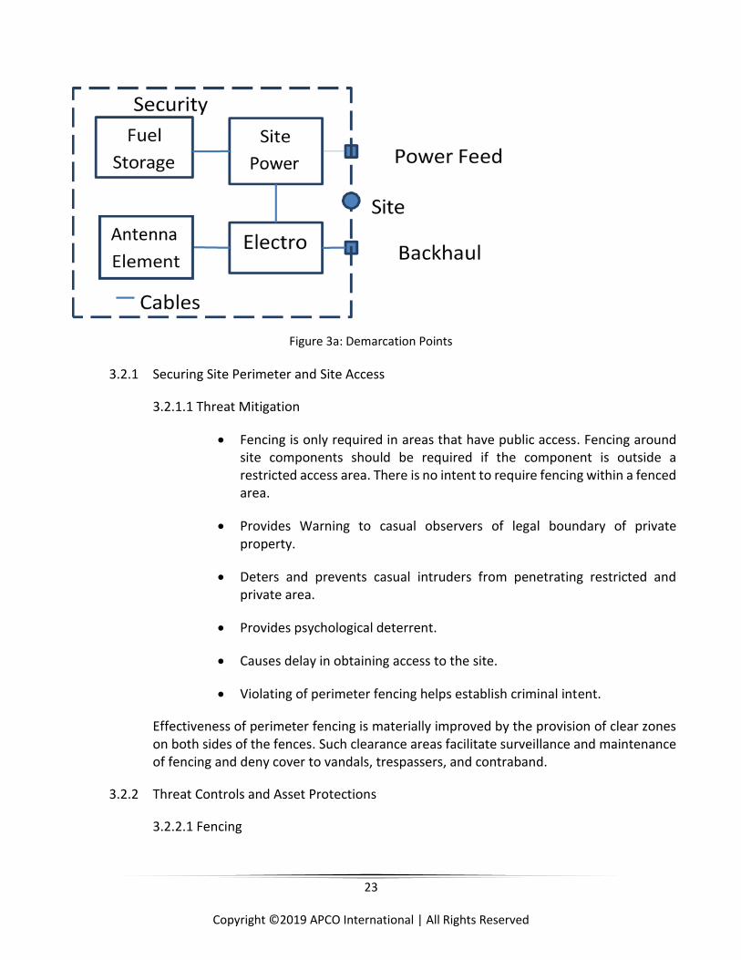
Demarcation points in text are identified to delineate assets that are within scope of the physical
security subsection. Assets and associated demarcation points are identified in the following
illustration:
23
Copyright ©2019 APCO International | All Rights Reserved
Figure 3a: Demarcation Points
3.2.1 Securing Site Perimeter and Site Access
3.2.1.1 Threat Mitigation
Fencing is only required in areas that have public access. Fencing around site components should be required if the component is outside a restricted access area. There is no intent to require fencing within a fenced area.
Provides Warning to casual observers of legal boundary of private property.
Deters and prevents casual intruders from penetrating restricted and private area.
Provides psychological deterrent.
Causes delay in obtaining access to the site.
Violating of perimeter fencing helps establish criminal intent.
Effectiveness of perimeter fencing is materially improved by the provision of clear zones on both sides of the fences. Such clearance areas facilitate surveillance and maintenance of fencing and deny cover to vandals, trespassers, and contraband.
3.2.2 Threat Controls and Asset Protections
3.2.2.1 Fencing
24
Copyright ©2019 APCO International | All Rights Reserved
Fencing shall be required around site components unless they are restricted from public access (e.g. located on locked roof top or within a secured compound).
Chain link fence fabric shall be constructed from minimum 9-gauge galvanized material with 1290 foot pounds of tensile strength.
Chain link fence fabric should have a mesh size of 1 inch with anti-cut, anti-climb material. No more than 2-inch mesh should be used as smaller mesh is more difficult to climb.
Chain link fence bottom shall be buried to reduce penetration at the base.
Chain link fence fabric shall have a minimum height of 8 feet (7 feet high with 1 foot of barbed at the top to discourage climbing).
Chain link fence fabric top section should include razor wire or 1-foot width of 3-strand, 4 barbed (12 gauge or better barbed wire) angled outward at 45 degrees.
Chain link fence frame shall consist of line posts, end posts, corner posts, gateposts, and if required - top, mid, bottom or brace rail.
Chain link fence frame shall have a minimum of Schedule 40 pipe of welded pipe and should be used with a minimum diameter of 2.875 inches.
Chain link fence frame shall be designed such that posts, bracing, and all other structural members are to be placed on the secure-side of the fencing.
Chain link fence frame should include the top rail secured to the fence fabric.
Chain link fence frame should consider weather and wind load when determining frame construction.
If a chain link fence cannot be used (e.g., due to design ordnances), then an 8-foot high non-scalable wall should be installed.
3.2.2.2 Gates
Gates shall be similar to or made of higher quality than the fence.
• Gates shall provide limited access for intruders while providing safe
passage for operators.
25
Copyright ©2019 APCO International | All Rights Reserved
• Gates should be securely and robustly lockable with a latch (e.g. using a ½-
inch casehardened steel chain and a padlock with a ½-inch casehardened
shackle and casehardened shell, electronic lock).
3.2.2.3 Clear Zones and Access
Clear zones (e.g., 3-foot min) should be designed for deterrence, detection of intruders and for defensible space to protect against wild land fire.
Clear zones should be free of climbable objects, trees, or utility poles abutting the fence line or areas for stackable crates, pallets, storage containers, or other materials.
Vehicles should be prevented from parking along the fence.
Landscaping within the clear zone should be minimized or eliminated to reduce potential hidden masking locations for persons, objects, fence damage, and vandalism.
3.2.2.4 Signage
• Signage should contain warnings and shall meet all local, state, and federal
regulations. This is to not only deter crime but to help in showing criminal
intent.
• Signage should not indicate site ownership or operational purpose. The
intent is to avoid governmental targeting.
• Signage should be installed at 50-foot intervals maximum.
• Signage should be 5 feet above the ground.
• Warning signs shall meet or exceed industry standard signage.
3.3 Antenna Structures
3.3.1 Threat Scenarios
The following scenarios could threaten the availability and/or integrity of antenna supporting structures or the site itself:
3.3.1.1 Removal or damage of structural steel components.
3.3.1.2 Removal or damage to guy wires.
3.3.1.3 Removal or damage to guy wire turnbuckles.
26
Copyright ©2019 APCO International | All Rights Reserved
3.3.1.4 Removal or damage of the grounding system.
3.3.2 Threat Assessments
The impact of any of the listed scenarios could cause the structure to degrade or collapse
which would cause complete operation of the site to fail. Because of the severity of
impact to the site, and the time to restore the structure, all identified threats should have
controls and protections in place.
3.3.3 Threat Controls and Asset Protections
3.3.3.1 The antenna supporting structure shall be protected with perimeter fencing per section 3.2.2.1.
3.3.3.2 The guy wire anchor shall be protected with perimeter fencing per section 3.2.2.1.
3.3.3.3 The guy wire turnbuckles shall be protected with safeties installed to protect them from being turned out.
3.3.4 Access points (e.g. gates and doors) shall be secured at all times.
3.3.4.1 Detection methods (e.g. video surveillance, ground bar disconnection alarm) should be deployed (e.g. if site is located in an area where higher than normal risk of vandalism is anticipated).
3.3.4.2 Motion sensing lighting should be installed at the base of the structure.
3.3.4.3 Protection and security of transmission lines and cables runs (e.g. anti-climb gates, underground runs, conduit encasement, and tower encasement) should be provided up to 12 feet above ground or roof grade.
3.4 Demarcation Points
3.4.1 Threat Scenarios
3.4.1.1 The following scenarios could threaten the availability and/or integrity of utility transformers, electrical meters, electrical disconnects, and telephone junction boxes, causing site to lose utility power or connectivity:
Removal or damage to the site’s electrical meters.
Damage or manipulation of the site’s electrical disconnects.
Damage to the site’s utility transformers.
Removal or damage to the site’s telephone junction boxes.
27
Copyright ©2019 APCO International | All Rights Reserved
3.4.2 Threat Assessments
The impact of the following scenarios could cause the site to lose utility power, and/or
communications. Loss of utility power would require the site to run off its back-up power
supply. Loss of communication may deliver the site inoperable. Because of the severity
of the impact to the site, and the time restore the effected components; all identified
threats should have controls and protections in place.
3.4.3 Threat Controls and Asset Protections
3.4.3.1 The site’s electrical meter shall be protected with perimeter fencing per section 3.2.2.1.
3.4.3.2 The site’s electrical disconnect(s) shall be protected with perimeter fencing per section 3.2.2.1
3.4.3.3 The site’s electrical disconnects shall be secured/locked to prevent the manipulation of disconnect if allowed.
3.4.3.4 The site’s utility transformer shall be protected from vehicle collision.
3.4.3.5 The site’s telephone junction boxes shall be protected from vehicle collision.
3.4.4 Access points (e.g. gates and doors) shall be secured at all times.
3.4.4.1 Sites electrical pedestal/meters shall be included within a fenced area of the site or within another secured area.
3.5 Cables, Wires, and Feed lines
3.5.1 Threat Scenarios
3.5.1.1 The following scenarios could threaten the availability of site operation if utility feeds, telephone lines, or antenna lines are made inoperable.
Damage to the site’s electrical feeds.
Damage to the site’s telephone lines.
Damage to the site’s antenna lines.
28
Copyright ©2019 APCO International | All Rights Reserved
3.5.2 Threat Assessments
The impact of any of the listed scenarios could cause the site to lose utility power, and /
or communications. Loss of utility power would require site to run off its back-up power
supply. Loss of communication may deliver the site inoperable. Because of the severity of
impact to the site, and the time to restore the effected components, all identified threats
should have controls and protections in place.
3.5.3 Threat Controls and Asset Protections
3.5.3.1 The site’s utility feed should be buried to prevent damage or disconnection of service.
3.5.3.2 The site’s telephone line(s) should be buried to prevent damage or disconnection of service.
3.5.3.3 The site’s antenna feed lines shall be secured behind the fencing.
3.5.3.4 The site’s antenna feed lines should be secured “inside” the tower structure when possible (e.g. within a monopole or inside the lattice members).
3.5.3.5 Shelter cable access ports (e.g. for power cables and antenna feed lines) should be protected from external fire ingress into the shelter.
3.5.3.6 If transmission lines or cables are installed above ground and environmental conditions require an ice bridge, then the site’s antenna feed lines and cables shall be secured to the underneath of an “ice bridge” in all cases to protect the lines (e.g. from ice or dropped tools).
3.5.3.7 Access gates, door, and other access points shall always be secured.
3.6 On-Site Fuel Storage
3.6.1 Threat Scenarios
3.6.1.1 The following scenarios could threaten the availability and/or integrity of the on-site fuel storage, or the site itself.
Malicious fuel ignition.
Accidental fuel ignition during maintenance and check or refill.
Malicious fuel theft.
Malicious fuel leak and/or loss.
29
Copyright ©2019 APCO International | All Rights Reserved
Accidental fuel leak and/or loss during maintenance check or refill.
3.6.1.2 Malicious fuel contamination.
3.6.1.3 Accidental fuel contamination during maintenance check or refill.
3.6.2 Threat Assessments
High-risk threats are fuel ignition and fuel theft. The moderate risk threats are fuel contamination and fuel leak and/or fuel loss. None of the identified threats are classified as low risk.
These risks apply equally to various site types, such as shelters, ground-based enclosures, tower-mounted electronics, and rooftop sites. However, there will be larger network impacts to “multi-function” sites, such as master sites, transport aggregation/hub sites, and shared LMR/LTE sites. As such, any prioritization of physical security controls or resources should consider the larger impact to multi-
3.6.3 Threat Controls
The security controls and protections for each scenario identified in the threat
assessments are recommended in this section.
3.6.3.1 Fuel tanks shall be protected from vehicular collisions (e.g. with peripheral bollards).
3.6.3.2 Bury or encase fuel tanks. Fuel tanks should be buried or encased in concrete materials (e.g. concrete masonry units). Either method should be designed by a licensed engineer or architect, follow local codes and ordinances, and account for substructures. Burial substructure considerations include local soil composition, stability, and drainage. Encasement substructure considerations include slab, footings, and roof load-bearing capability.
3.6.3.3 Secure access to fuel fill/drain ports. Fuel fill ports and drain ports (if applicable) shall be access controlled. Access controls should be provided by other physical site security controls (e.g. site perimeter fencing).
3.6.3.4 Secure access to vent ports. Fuel tank vent ports (if applicable) should be protected such that only air or fuel-vapor can pass through the vent port (e.g., per Uniform Fire Codes). Access controls should be provided by specific port controls (e.g., multi-layer mesh shields). A less secure alternative should be provided by other physical site security controls (e.g., site perimeter fencing).
30
Copyright ©2019 APCO International | All Rights Reserved
3.6.3.5 Secure Site Access. The site shall be access controlled. See Securing Site Perimeter and Site Access, section 3.2.1, of this document. Site access authorizations should be role-based and adhere to minimum privilege principles. This principle ensures that access privileges are segmented according to the role or function, and that minimum privileges are granted in accordance with the need to perform a role or function.
3.6.3.6 Each fuel tank should be equipped with a fuel level sensor. The fuel level sensor should be integrated into the site monitoring system so that fuel levels can be remotely monitored from the network operating center (NOC) or systems operating center (SOC). A low fuel level alarm should be implemented in the site monitoring system so that the fuel level can be remotely monitored from the NOC/SOC.
3.6.3.7 Each fuel tank should be equipped with fuel fill/drain port open/closed sensors. The fuel fill/drain port open/closed sensors should be integrated into the site monitoring system so that fuel port open/closed status can be remotely monitored from the NOC/SOC. A port open alarm should be enabled in the NOC/SOC alarm system.
3.6.3.8 The site generator should be equipped with a failed start sensor. The failed start sensor should be integrated into the site monitoring system so that the generator start status can be remotely monitored from the NOC/SOC. A failed start alarm should be enabled in the NOC/SOC alarm system.
3.6.3.9 The site should be equipped with one or more remote cameras. The field of view for one or more of the remote camera(s) should include the fuel storage tank location. The remote camera(s) video feed should be monitored from the NOC/SOC.
3.6.3.10 The site should be equipped with a remote video recording system. The video recording should be motion triggered or triggered from the NOC (Network Operations Center)/SOC (System Operations Center).
3.6.3.11 The site should be equipped with a local site audible siren. The audible siren should also have capability to be remotely activated/deactivated from the NOC/SOC.
3.7 On-Site Generator, Battery Plant, and Other Power Sources
3.7.1 Threat Scenarios
The following scenarios could threaten the availability of site operation if the on-site
generator, battery plant, or other power sources are made inoperable.
31
Copyright ©2019 APCO International | All Rights Reserved
3.7.1.1 Malicious damage to the site’s generator.
3.7.1.2 Accidental damage to the site’s generator.
3.7.1.3 Malicious damage to the site’s battery plant.
3.7.1.4 Accidental damage to the site’s battery plant.
3.7.1.5 Malicious damage to the site’s alternative power sources.
3.7.1.6 Accidental damage to the site’s alternative sources (i.e. solar power).
3.7.2 Threat Assessments
The on-site generator, battery plant, and other alternative power sources represent the
back-up power necessary to keep the site operating should the main utility power be
interrupted. The impact of any of the listed scenarios, in conjunction with an interruption
of utility power could cause the site to shut down completely with a total loss of
communications. Because of the severity of impact to the site, and the time to restore
the effected components, all identified threats should have controls and protections in
place. The specific nature of the protections afforded to the power sources will depend
upon their location within the site.
Separate protection mechanisms, e.g., video surveillance, are not required if the power
sources are protected by the same mechanisms used for the shelter or other components
in the site.
3.7.3 Threat Controls and Asset Protections
3.7.3.1 Access to the on-site generator shall be limited to authorized personnel.
3.7.3.2 Generator shall be completely enclosed in an enclosure with access limited to authorized personnel.
3.7.3.3 Batteries shall be completely enclosed in a secure cabinet or structure enclosure with access limited to authorize personnel.
3.7.3.4 Batteries and battery connections shall be protected from accidental contact. (e.g., where tools and other conductive materials cannot accidently be dropped on them).
3.7.3.5 Alternative power sources such as solar panels shall be installed in secured locations out of reach to unauthorized persons.
32
Copyright ©2019 APCO International | All Rights Reserved
3.7.3.6 Alternative power sources such as solar panels should be protected from regionally defined hazards and debris (e.g., falling objects from the on-site tower).
3.7.3.7 Video surveillance of on-site generator should be installed. In a high-risk area, video surveillance shall be installed.
3.7.3.8 Generator open door sensors shall be installed.
3.7.3.9 Access to on-site generator should have a capability to remotely manage access authentication.
3.7.3.10 Access to site’s battery plant should have a capability to remotely manage access authentication.
3.7.3.11 Video surveillance of on-site alternative power sources such as solar panels shall be installed.
3.8 Securing On-Site Electronics Shelters and Enclosures
3.8.1 Threat Scenarios
The following scenarios can threaten the availability and/or integrity of the shelters and
enclosures, or the site itself:
3.8.1.1 Compromised access: Unauthorized access, malicious access, accidental unsecured site.
3.8.1.2 Physical attack: Manual (tools), firearms, vehicle.
3.8.1.3 Fire: Malicious fire.
3.8.2 Threat Assessments
The specific nature of the protections afforded to the on-site electronics shelters and
enclosures will depend upon their location within the site. Separate protection
mechanisms, e.g., video surveillance, are not required if the shelters and enclosures are
protected by the same mechanisms used elsewhere in the site, e.g., if the site is physically
located on a fire station staffed 24x7 with existing video surveillance and similar
mechanisms.
Requirements for Securing On-Site Electronics Shelters and Enclosures
3.8.2.1 Bollards should be installed around the site perimeter and/or around site components, which are susceptible to vehicular collision (e.g., fuel tanks).
33
Copyright ©2019 APCO International | All Rights Reserved
3.8.2.2 Gate alarm system should be implemented.
3.8.2.3 Door alarm system shall be implemented.
3.8.2.4 Door lock status/operation monitor system shall be implemented, where feasible.
3.8.2.5 Security / tamper-proof hardware shall be used.
3.8.2.6 Self-closing doors shall be used.
3.8.2.7 Motion detector system shall be implemented in high-risk areas as well within the protected compound.
3.8.2.8 Video monitoring system (Interior/Exterior) shall be implemented with digital-video- recording systems.
3.8.2.9 All alarms and monitoring tools shall be connected and monitored by a NOC or SOC.
3.8.2.10 Smoke/fire alarm system shall be implemented and monitored for shelters.
3.8.2.11 Bullet-resistant materials and hardware should be used.
3.8.2.12 Audible intrusion siren should be implemented.
3.8.2.13 Attack, Detection, Response, and Recovery
3.8.2.14 The site should be equipped with one or more remote cameras. The field of view for one or more of the remote camera(s) should include the exterior of the shelter/site, including typical access gate and door and any vulnerable access or hazard views. The field of view for one or more of the remote camera(s) should include the interior of the shelter/site, including the interior of the door and sufficient view of overall interior.
3.8.2.15 The remote camera(s) video feed should be monitored (or monitor capable) from the NOC/SOC and/or local law enforcement if applicable.
3.8.2.16 The site should be equipped with a remote video recording system. The video recording should be motion/event triggered or triggered from NOC/SOC. Use of constant or loop recording should be considered.
3.8.2.17 The site should be equipped with local site audible alarm. The audible alarm should be triggered from the NOC/SOC.
34
Copyright ©2019 APCO International | All Rights Reserved
3.9 Antenna Support Structure
These antenna support structure requirements address the necessary steps to provide reliable
and robust structures to support communications site apparatus above ground level. This
generally includes antennas and associated radio frequency cables, but can also include tower
mounted equipment such as low noise amplifiers.
3.9.1 New Antenna Supporting Structure Design
This section will provide requirements for new antenna supporting structure design.
Additional or future loading of such new antenna supporting structure is not a
consideration of this section but should be determined by the new antenna structure
owner(s) as required. Please note that exposure and topographic categories for each new
structure will be determined based on the interpretation of the location of the new
antenna supporting structure by the design engineer and structure owner(s).
3.9.1.1 The design of all new antenna support structures shall comply with the most current revision of ANSI/TIA-222, Class III.
3.9.1.2 All newly constructed antenna structures shall comply with all applicable local, county, state, or federal jurisdictional requirements. Antenna support structures should be elevated if practical to preclude water damage if located within 100 and 500-year flood plains.
3.9.1.3 The most current version of ANSI/TIA-222 specification contains new parameters that significantly affect the magnitude of wind, ice, and earthquake loading for class III structures. Loadings are increased for structures of public safety Class III classification compared to Class II structures by 15 percent for wind, 25 percent for ice, and 50 percent for earthquakes. The earthquake requirements are confined to regions defined as having high seismic activity and are clearly identified in the standard. These requirements do not preclude applicable local, county, state, or federal jurisdictional requirements. Prior to construction of any new antenna structures full compliance with all applicable building standards and zoning laws shall be verified.
3.9.2 Existing Antenna Supporting Structures
This section will provide requirements for the structural analysis and potential upgrades
of existing antenna supporting structures. A rigorous structural analysis for each existing
antenna supporting structure is required prior to the installation of new antennas unless
the installation of the new antennas has been determined to fall within the current
version of ANSI/TIA-222. This determination should be made by the engineer performing
the rigorous structural analysis. Please note that exposure and topographic categories for
35
Copyright ©2019 APCO International | All Rights Reserved
each existing antenna supporting structure will be determined based on the
interpretation of location of the existing antenna supporting structure by the engineer
performing the rigorous structural analysis and structure owner(s).
3.9.2.1 A rigorous structural analysis shall be required for each existing antenna supporting structure prior to the installation of new antennas, lines, or appurtenances unless the installation of such items has been determined to fall within the most recent version of ANSI/TIA-222 (including all amendments). This determination shall be made by towers owner and properly licensed Professional Engineer (PE) or Structural Engineer (SE) performing the structural analysis. The determination should be in writing and signed off by the tower owner as well as signed and sealed by the jurisdictionally licensed PE or SE who performed the analysis.
3.9.2.2 All existing antenna support structures shall be compliant with the most recent version of ANSI/TIA-222 Class II.
3.9.2.3 All existing antenna support structures should be compliant with the most recent version of ANSI/TIA-222 Class III.
3.9.2.4 All existing antenna support structures which require upgrades or modifications shall comply with the most recent version of ANSI/TIA-222 and ANSI/TIA-1019A.
3.9.2.5 Towers types include self-support, guyed or monopole.
3.9.2.6 ANSI/TIA-222 shall govern the structural analysis requirements for modifications and upgrades. While previous revisions of ANSI/TIA-222 allowed the use of existing tower structures, all modifications and upgrades moving forward shall follow the most current version of ANSI/TIA-222 and ANSI/TIA-1019A.Ensuring the structural integrity after modifications and upgrades (or no overstress beyond the safety factor of the original design parameters) of the existing antenna support structure and its foundation are paramount to verify before utilizing it. Additionally, ensuring that existing antenna support structure (after modifications and upgrades) meet the twist and sway specifications (thus the five or six nines reliability and/or availability) of the intended end user are of the utmost concern before utilizing it.
3.9.3 Other Existing Antenna Supporting Structures
This section will provide requirements for the structural analysis and potential upgrades
of other existing antenna supporting structures. A rigorous structural analysis for each
existing antenna supporting structure is required prior to the installation of new antennas
unless the installation of the new antennas has been determined to fall within the most
recent version of ANSI/TIA-222. This determination should be made by the engineer
36
Copyright ©2019 APCO International | All Rights Reserved
performing the rigorous structural analysis. Please note that exposure and topographic
categories for each existing antenna supporting structure will be determined based on
the interpretation of location of the existing antenna supporting structure by the engineer
performing the rigorous structural analysis and structure owner(s).
3.9.3.1 All other antenna supporting structure types shall comply with the most current revision of ANSI/TIA-222, Class II for structural analysis and ANSI/TIA-1019A for all upgrades and modifications.
3.9.3.2 All other antenna support structure types should comply with the most current revision of ANSI/TIA-222, Class III for structural analysis as applicable for all upgrades and modifications.
3.9.3.3 All existing antenna support structures which require upgrades or modifications shall comply with the most current revision of ANSI/TIA-222 and ANSI/TIA-1019A.
3.9.4 Other Structures (e.g. billboards, specialty)
Use of antenna support structures that cannot be designed to or comply with the most
current revision of ANSI/TIA-222 and do not meet twist and sway requirements of the end
user are discouraged.
3.10 Lightning Protection, Electromagnetic Pulse (EMP) Protection and Grounding
This section will provide requirements for lightning protection, EMP6 and grounding, both
external and internal, which when implemented will be considered PSG for this category. To
disperse lightning and EMP energy into the earth without causing dangerous over-voltage, the
shape and dimensions of the grounding (earthing) electrode system are more important than a
specific resistance value of the grounding electrode system. However, a low resistance and low
impedance grounding electrode system is recommended (IEC 61024-1-2). Attempts should be
made to reduce the grounding electrode system resistance to the lowest practical value (MIL-
HDBK- 419A). Refer to Motorola R56 grounding guidelines.
3.10.1 A “single point” grounding concept is required. This includes a single ground point located at all the outside shelter or equipment room penetrations [RF, AC (Alternate Current) power, generator, GPS (Global Position Satellite), tower light controllers, equipment and phone lines]. This design will affect the overall equipment layout. DC (Direct Current) power systems should also logically be located close to this ground point. Though this uses up some wall and floor space, it permits the systematic growth of communications equipment outward.
6 Latest version of the National Coordinating Center for Communications (NCC) Electromagnetic Pulse (EMP) Protection and resilience Guidelines for Critical Infrastructure and Equipment.
37
Copyright ©2019 APCO International | All Rights Reserved
3.10.2 External grounding shall be a common grounding system, which complies with National Electric Code (NEC).
3.10.3 Sites shall achieve a grounding (earthing) electrode system resistance not to exceed 5 ohms.
3.10.4 The sites should achieve a grounding (earthing) electrode system resistance of 1 ohm.
3.10.5 Sites in high lightning prone geographical areas, and sites normally occupied (such as dispatch centers), should include enhancements to the grounding electrode system per the most current version of ANSI T1.334.
3.10.6 Grounding electrode system enhancements should include installation of radial grounding conductors, installation of concrete encased electrodes in new construction, and installation of longer ground rods.
3.10.7 Lightning and EMP arrestor and surge protection systems shall be compliant with the latest revision of NFPA-780, UL-1449, and UL-96A.
3.10.8 Power surge protection devices (SPDs) shall alert the operator or user when they are no longer fully functional.
3.10.9 RF SPDs shall be replaced per the manufacturer’s recommendations or, if feasible, shall alert the operator or user when they are no longer fully functional.
3.10.10 Spare power, RF, and data SPDs should be kept on hand, both to help ensure quick replacement of existing SPDs when needed and to help recover from systemic failures.
3.10.11 SPDs should be EMP rated protecting against rise times as fast as 10 nanoseconds (ns).
3.10.12 More critical installations should ensure that the SPD EMP testing is per International Electrotechnical Commission (IEC) EMP and IEMI protection standards or per Military Standards such as MIL-STD-188-125-1 or MIL-HDBK-423.
3.10.13 All outdoor cables containing metal shall be shielded with the shielding properly grounded (double shielding is preferred).
3.10.14 For data cables, fiber optic cables without metal are preferred, particularly for lengths over 100 m.
3.10.15 Spare equipment should be stored in an EMP resilient area with all cables disconnected where feasible.
38
Copyright ©2019 APCO International | All Rights Reserved
3.10.16 All cable tray sections shall be electrically bonded together by an approve method and connected to the building ground system. The cable tray system shall be grounded to the room single point ground position MGB (Master Ground Bar) only.
3.10.17 Grounding electrodes, conductors, connection devices, and bus bars shall be listed (UL 467 or equivalent) and installed in compliance with current industry standards and best practices.
3.10.18 External grounding conductors shall be #2 AWG (American Wire Gauge) or coarser, bare, solid, tinned copper.
3.10.19 The radio facility shall comply with NFPA 70, NFPA 780 and Motorola R56.
3.10.20 Newly constructed radio facilities shall incorporate a concrete encased electrode (Ufer) in the footer of the building as an integral part of the buildings common grounding electrode system. (NFPA 70 and NFPA 780).
3.10.21 The facility shall have an intersystem bonding termination (IBT) external to enclosures at the electrical service-entrance equipment or metering equipment enclosure and at the disconnecting means for any additional buildings or structures. (NFPA 70 Bonding for Other Systems)
3.10.22 The facility shall have a master ground bus bar (MGB) installed within 24 inches of the RF cable entrance to serve as the single point internal ground and provide a convenient grounding location for RF SPD. (NFPA 70 Bonding for Other Systems)
3.10.23 The master ground bus bar shall be bonded to the common external grounding system and when located more than 20 feet away from the MGB shall be bonded to the common external grounding system. A subsystem ground bus bar shall be installed within 24 inches below each secondary RF cable entrance to provide a grounding point for RF cable surge protection devices.
3.10.24 The subsystem ground bus bar shall be bonded to the master ground bus bar and grounded to the common external grounding system.
3.10.25 For new single-story building construction, vertical structural steel members shall be “effectively” bonded to a concrete encased electrode. (NFPA 70).
3.10.26 A telecommunications master ground bus bar Telecommunications Master Ground Bus Bar shall be installed near the primary telecommunications service- entrance. The Telecommunications Master Ground Bus Bar should be in the primary telecommunications equipment room where the telecommunication service-entrance is established separate from the electrical service-entrance.
39
Copyright ©2019 APCO International | All Rights Reserved
3.10.27 All incoming telecommunication cables, including paired-conductors and optical fiber cable at the telecommunications service-entrance shall be grounded to the common building grounding system.
3.10.28 Each SPD for telephone circuits, data circuits, and control circuits shall be connected to the single point ground with a #6 AWG or coarser grounding conductor using UL 467-listed (or equivalent) grounding connectors. The size of the bonding conductor shall be based on distance (reference Motorola R56).
3.10.29 Lightning protection systems should be installed where required by NFPA 780 or local regulations.
3.10.30 If it is determined that a lightning protection system is not necessary, a written document prepared by a qualified engineer justifying why a lightning protection system is not necessary shall be prepared. This document shall specifically address the exposure criteria provided below and include appropriate references, results from soil resistivity testing, and elevation measurements used to justify not installing a lightning protection system.
3.10.31 Building ground rings and tower ground rings shall be bonded together in at least two points using a main sized ground electrode conductor #2 AWG or coarser, bare, solid, tinned or un-tinned, copper conductor with conductors physically separated to the extent practical. Only tinned conductors and components should be used on exterior grounding systems. All buried connections to the ground rings shall be exothermically welded.
3.11 Equipment Enclosures
This section will provide requirements for the use and potential upgrades of communications
equipment shelters and cabinets which, when implemented, will be considered PSG for this
category. A shelter is defined as a structure used to house communications equipment, which is
large enough to allow physical entry by one or more support personnel. A cabinet is defined as
a structure used to house communications equipment which is not designed for, or large enough
to, allow entry by one or more personnel.
3.11.1 Shelter Requirements
3.11.1.1 Shelter walls, roof, and doors shall at a minimum have a 150 MPH static wind rating in accordance with the latest revision of ASCE-7.
3.11.1.2 State wind loads requirements shall meet or exceed the requirements of latest revision of ASCE-7.
40
Copyright ©2019 APCO International | All Rights Reserved
3.11.1.3 All shelters shall have their interior climate conditions monitored and/or alarmed. Low and high temperature and humidity set points shall be established and monitored.
3.11.1.4 Shelters shall be constructed using fire resistant materials designed to keep critical components to below 125°F to maintain operational serviceability for at least 2 hours and at a minimum meet the latest revision of NFPA 76.
3.11.1.5 Equipment enclosures attached to shelters shall meet NEMA (Association of Electrical Equipment and Medical Engineering Imaging Manufacturers) 4 and 4x standards as described in the latest version of NEMA 250. Shelter weather proofing at a minimum shall provide protection against the ingress of solid foreign objects (dirt) and protection from the harmful effects on the equipment due to the ingress of water (rain, sleet, snow).
3.11.1.6 Shelter walls, roof, and doors shall at a minimum meet the latest revision of UL-752 bullet resistance level four testing criteria.
3.11.1.7 Shelters shall be elevated to preclude water damage if located within the 100 and 500-year flood plains or other areas prone to flooding.
3.11.2 Cabinets Requirements
3.11.2.1 All cabinets shall be equipped with a temperature sensing and alarm system, which should be capable of remote monitoring.
3.11.2.2 Cabinet walls, roof and doors shall at a minimum have a 150-mph static wind rating in accordance with the latest revision of ASCE-7. Regions with greater wind requirements, in accordance with latest revision of ASCE-7, shall apply to shelters located within those regions.
3.11.2.3 Cabinets should be constructed using fire resistant materials designed to keep critical electrical circuits to below 125 degrees Fahrenheit to maintain operational serviceability for at least 2 hours and at a minimum meet the latest version NFPA 76.
3.11.2.4 Cabinets shall meet NEMA 4 and 4x standards as described in the latest version of NEMA 250. Weather proofing at a minimum shall provide protection against the ingress of solid foreign objects (dirt) and protection from the harmful effects on the equipment due to the ingress of water (rain, sleet, snow) and will be undamaged by the formation of external ice.
3.11.2.5 Cabinet walls, roof, and doors should, at a minimum, meet UL 752 bullet resistance level 4 testing criteria where circumstances and risks warrant.

41
Copyright ©2019 APCO International | All Rights Reserved
3.11.2.6 Cabinets shall be elevated to preclude water damage if located within the 100 and 500-year flood plains or other areas prone to flooding.
3.12 Environmental and Climate Control
This section will provide minimum design requirements for the use and potential upgrades of
environmental control systems to include heating and cooling of any structure or enclosure
which, when implemented, will be considered PSG for this category.
3.12.1 Climate control systems shall be able to maintain an optimum operating temperature and humidity level consistent with manufacturer specifications, peak performance and long-term reliability of all equipment and batteries installed within an enclosure.
3.12.2 The AHJ shall comply with all codes and regulations concerning the use of wet cell batteries.
3.12.3 Climate control systems shall be designed and sized to environmentally control the space inside the enclosure to minimally accommodate the peak heat load of the components inside the enclosure as well as the peak load presented by the external environment surrounding the enclosure.
3.12.4 Diversity and design of climate control systems should allow for backup to the primary system(s).
3.13 Power
Clean, reliable electrical power is paramount to communications sites. Availability of power to
communications equipment is the fundamental limiting factor regarding the in-service state of
the equipment. The causes of loss in commercial power can vary from natural events such as ice
storms and high winds to manmade failures such as overload of the power grid. When failures
occur, they often persist for several hours or days until downed lines can be restored. With some
natural disasters (e.g., hurricanes) or manmade events (e.g., high altitude EMP attack), the
outages could occur for weeks or even months. As a result, communications systems, to be highly
resilient, shall have immediate and long-term backup sources. The power systems themselves
shall include redundant components to protect against failures and cybersecurity attacks as well
as include components that protect the power systems from upstream power system
deficiencies.
3.13.1 General Electrical Requirements
Each site has different levels of criticality that would affect the operations of the network.
Each site shall be addressed individually based on its network operation and ability to
provide users continuous and reliable connectivity and data throughput. Every site layout
42
Copyright ©2019 APCO International | All Rights Reserved
shall identify and rectify any single point(s) of failure that would interrupt service affect
site availability.
3.13.1.1 AC (alternating current) power systems shall be designed installed and maintained adhering to the current NFPA 70/NEC codes and/or local jurisdictional codes utilizing the most stringent.
3.13.1.2 Future expansion of the site shall be considered during the electrical systems design.
3.13.1.3 Operating loads shall not be more than 80% of the electrical systems capacity.
3.13.1.4 The current edition of NFPA or the local jurisdiction’s code, whichever is more stringent shall be considered for circuit/feeder design and conductor selections.
3.13.1.5 At all sites, there is either, or both, a main service disconnect and a fused disconnect. A main service disconnect should be located at a meter location away from the building. A main disconnect located within the shelter, equipment room, or area should be fed by a feeder circuit originating at a main service disconnect located in an electrical room in a different location in the building or even a separate building. Typically, the neutral and ground conductors are bonded in the main service disconnect. When the main service disconnect is located remotely from the equipment room or area, a separately derived system should be installed in the equipment room. See current edition of NFPA 70 for additional information. One of the reasons for the separately derived system is to reestablish the neutral/ground bond, thereby improving the effectiveness of normal mode suppression. See figure 3b below within this section.
3.13.1.6 Circuit breakers shall be sized to protect the conductor attached to them and not the load (current edition of NFPA 70).
3.13.1.7 A panel schedule shall be filled out (current edition of NFPA 70).
3.13.1.8 All branch conductors shall be copper to reduce corrosion and impedance due to dissimilar materials.
3.13.1.9 Branch conductors shall have an allowable ampacity equal or greater to the non-continuous load plus 125% of the continuous load (current edition of NFPA 70).
3.13.1.10 Alternating Current Equipment Ground (ACEG) shall be sized according to NFPA 70 (see figure 3b).
43
Copyright ©2019 APCO International | All Rights Reserved
3.13.1.11 Extension cords shall not be used to power permanent equipment.
3.13.1.12 All interior surface mounted building wiring shall be in electrical metallic tubing (EMT) or raceways (current edition of NFPA 70).
3.13.1.13 Conduit shall not be used as the AC equipment ground conductor.
3.13.1.14 An Over Current Protection Device (OCPD) shall always be installed before all other panels and equipment, including a generator transfer switch.
3.13.1.15 The following are required thresholds when testing AC power quality in most single-phase and three-phase configurations (current version of IEEE STD 1100). The actual thresholds used shall be based on the installation requirements of the connected equipment, as the connected equipment should have more stringent requirements. See current version of IEEE STD 1159 for additional information.
Phase Voltage Testing Thresholds
Frequency Deviation shall not exceed ± 0.5 Hz
High Frequency Noise shall not exceed approximately 1% of the phase-neutral voltage
Voltage Sags shall be less than –10% of nominal supply voltage (108 V for a 120 VAC circuit)
Voltage Swells shall not exceed +5% of nominal supply voltage (126 V for a 120 VAC circuit)
Transients should not exceed approximately 100 V over the nominal phase- neutral voltage
Distortion shall not be more than 5% Total Harmonic Distortion (THD) – the voltage distortion level at which loads may be affected
Neutral-ground Voltage Testing Thresholds
High Frequency Noise shall not exceed 2-3 peak volts
Voltage Swells shall not exceed 1% to 2.5% of nominal phase-neutral voltage
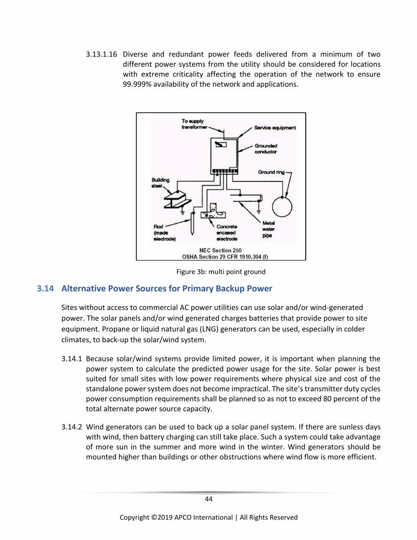
44
Copyright ©2019 APCO International | All Rights Reserved
3.13.1.16 Diverse and redundant power feeds delivered from a minimum of two different power systems from the utility should be considered for locations with extreme criticality affecting the operation of the network to ensure 99.999% availability of the network and applications.
Figure 3b: multi point ground
3.14 Alternative Power Sources for Primary Backup Power
Sites without access to commercial AC power utilities can use solar and/or wind-generated
power. The solar panels and/or wind generated charges batteries that provide power to site
equipment. Propane or liquid natural gas (LNG) generators can be used, especially in colder
climates, to back-up the solar/wind system.
3.14.1 Because solar/wind systems provide limited power, it is important when planning the power system to calculate the predicted power usage for the site. Solar power is best suited for small sites with low power requirements where physical size and cost of the standalone power system does not become impractical. The site’s transmitter duty cycles power consumption requirements shall be planned so as not to exceed 80 percent of the total alternate power source capacity.
3.14.2 Wind generators can be used to back up a solar panel system. If there are sunless days with wind, then battery charging can still take place. Such a system could take advantage of more sun in the summer and more wind in the winter. Wind generators should be mounted higher than buildings or other obstructions where wind flow is more efficient.
45
Copyright ©2019 APCO International | All Rights Reserved
3.14.3 Hydrogen fuel cells are a potentially viable option for backup power, particularly in the telecommunications sector. Traditional backup power technologies use batteries and generators that operate on diesel, propane, or gasoline. Most backup-power communications and control systems use a combination of generators and batteries to provide redundancy and avoid service disruptions. Although these systems are reliable and well established, growing concerns about batteries and generators are motivating many customers to seek alternatives that provide high reliability and durability at reasonable cost. Compared with batteries, fuel cells offer longer continuous runtime and greater durability in harsh outdoor environments. With fewer moving parts, they require less maintenance than generators or batteries. They can also be monitored remotely, reducing maintenance time. Compared with generators, fuel cells are quieter and have no harmful emissions. On a lifecycle basis, fuel cells can offer significant cost savings over both battery-generator systems and battery-only systems when shorter runtime capabilities of up to 72 hours are sufficient (fuel cell system costs for longer runtimes can be higher than incumbent technologies due to the cost of hydrogen storage tank rentals).
3.14.4 Solar or wind system battery storage shall be designed to supply adequate power to the site for sites without an additional alternative source (e.g., generator) of power to replace the primary power generation to deliver 99.999% availability given the expected weather conditions (i.e., as a function of the expected availability of sun and wind resources).
3.14.5 Solar panels shall be oversized by minimum 10% of calculated load.
3.14.6 The electronics within both solar and wind systems shall follow the guidelines under the “Lightning and EMP Protection and Grounding” section in this document. This includes providing lightning and EMP surge protection to all electrical components.
3.15 Long Term Back-Up Power
There are many long term fixed and mobile backup power sources. This section addresses these
units and fuel types available.
3.15.1 Each site shall have a backup power generation with a power supply duration sized to power the site until it can be refueled to maintain 99.999% availability. Fuel supply shall have a minimum reserve of 72 hours before being refueled (NFPA 1221).
3.15.2 The fuel source for the generator shall be chosen to provide reliable generator operation given the site’s climate and other environmental factors.
3.15.3 Fixed generators with onsite fuel storage shall have an adequately sized storage to allow for the unit to operate at full load for the longest expected runtime given distance from supplies and the potential for transportation disruption during a disaster or power outage. Fuel supply shall have a minimum reserve of 72 hours before being refueled (NFPA 1221).
46
Copyright ©2019 APCO International | All Rights Reserved
3.15.4 System(s) shall have adequate capacity to carry ALL loads at full capacity when sizing the long-term power source equipment.
3.15.5 System(s) should have adequate capacity to carry ALL loads at full capacity plus 30% expansion factor when sizing the long-term power source equipment.
3.15.6 When sizing long-term power source equipment, derating per manufacturer’s specifications shall be calculated for altitude, installation location, voltage/phase configuration, and fuel and load type.
3.15.7 Based on the environmental characteristics of a site, generators and fuel storage shall be in an area protecting them from flooding and should address other physical hazards as follows: blowing derbies, falling ice, and frequent extreme weather.
3.15.8 In areas prone to seismic activity fuel lines and connections shall meet local seismic codes for the fuel type utilized.
3.15.9 Generators shall be monitored for alarms as stated in NFPA 110 for a level 1 generator. There shall be a low-level coolant trouble alarm before unit shutdown on low coolant.
3.15.10 The capability to view oil pressure and engine temperature shall be installed on the generator.
3.15.11 Voltage, amperage, and frequency meter(s) shall be installed either at the generator, transfer switch or both.
3.15.12 Any additional alarms or indicators should be considered to provide early detection of impending issues. A fail to transfer alarm should be considered to indicate the generator is running however it is not powering the load.
3.15.13 Engine, stator, control panel, and battery heaters should also be considered on the location of the unit.
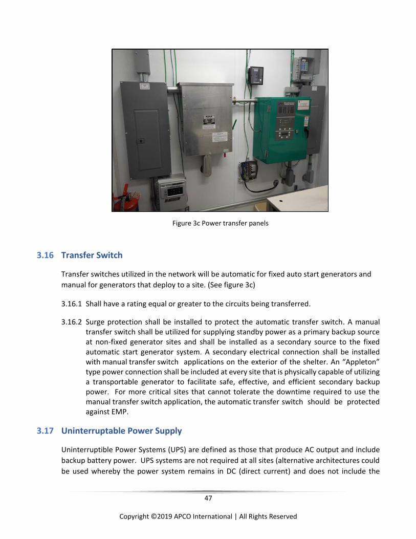
47
Copyright ©2019 APCO International | All Rights Reserved
Figure 3c Power transfer panels
3.16 Transfer Switch
Transfer switches utilized in the network will be automatic for fixed auto start generators and
manual for generators that deploy to a site. (See figure 3c)
3.16.1 Shall have a rating equal or greater to the circuits being transferred.
3.16.2 Surge protection shall be installed to protect the automatic transfer switch. A manual transfer switch shall be utilized for supplying standby power as a primary backup source at non-fixed generator sites and shall be installed as a secondary source to the fixed automatic start generator system. A secondary electrical connection shall be installed with manual transfer switch applications on the exterior of the shelter. An “Appleton” type power connection shall be included at every site that is physically capable of utilizing a transportable generator to facilitate safe, effective, and efficient secondary backup power. For more critical sites that cannot tolerate the downtime required to use the manual transfer switch application, the automatic transfer switch should be protected against EMP.
3.17 Uninterruptable Power Supply
Uninterruptible Power Systems (UPS) are defined as those that produce AC output and include
backup battery power. UPS systems are not required at all sites (alternative architectures could
be used whereby the power system remains in DC (direct current) and does not include the
48
Copyright ©2019 APCO International | All Rights Reserved
additional conversion back to AC. When employed, the following requirements define public
safety grade sites. UPS systems are typically intended to provide short-term power to specific
loads when there are transient disruptions or short-term power outages. UPS system(s) are
typically intended to provide transition power between power loss and generator online.
3.17.1 When utilizing a UPS system(s), two distinct power panels shall be utilized, an equipment panel (UPS panel board) and utility power panel.
3.17.2 UPS system shall deliver a true sinusoidal output.
3.17.3 Since UPS systems are typically used for “short-term” operation backup time is usually less than what a rectifier system typically is designed for. The unit(s) ability to perform in an “extended run-time” scenario should be considered in the design.
3.17.4 The UPS shall be capable of dry contact alarms as well as SNMP (Simple Network Management Tool) to identify the following alarm conditions: minor, running on inverter, pre-low battery, pre-low runtime, internal temperature, major, low battery, and low runtime. At a minimum minor and major shall be available.
3.17.5 Recharge time for a fully discharged battery array shall be no more than 12-16 hours for sealed lead acid.
3.17.6 A bypass shall be installed for UPS systems in the event of equipment failure, such that power maybe restored to the system(s) by bypassing the equipment. A make-before-break shall be utilized unless it is not approved by UPS manufacturer due to power configuration.
3.18 Rectifier System
The following section addresses the rectifier requirements for PSG sites. These requirements
apply to “DC only” sites, whereby a UPS is not used. In other words, these requirements apply in
those situations where AC is converted to DC by the Rectifier System and the power is not
inverted back to AC to power the electronic systems. These rectifier requirements do not apply
to the rectifiers that would be part of a UPS system.
3.18.1 DC equipment shall be powered via n+ 1 redundant rectifier whereby one additional rectifier beyond the required number to meet the load is included.
3.18.2 UL-listed general use or battery cable shall be used in DC systems.
3.18.3 Overcurrent protection shall be 50% larger than calculated load but not larger than the conductors rating. Conductors shall be based on their calculated load requirements and current carrying capacity.
49
Copyright ©2019 APCO International | All Rights Reserved
3.18.4 DC systems incorporating a battery backup shall be equipped with a Low Voltage Load Disconnect (LVLD). A Low Voltage Battery Disconnect (LVBD) shall not replace or be substituted for the LVLD.
3.18.5 The rectifier system shall be capable of dry contact alarms and/ or SNMP to identify the following alarm conditions: over and under charging alarms.
3.19 Batteries
These battery requirements do not apply in situations where a UPS is used. They apply in
situations when power is converted to DC via a rectifier system and it remains in DC to power the
electronic systems. Batteries that are used fall into two categories: flooded cell (wet) and valve
regulated (sealed). Wet cell batteries pose a greater hazard vs. sealed batteries due to hydrogen
gas being emitted during operation. Sealed Absorbed Glass Mat (AGM) batteries are preferred.
If wet cell batteries are utilized, then the following shall be addressed.
3.19.1 Battery system shall be designed to allow technicians to respond to the site after an outage. Running on battery operation at 100% load shall be utilized for calculating the runtime to maintain 99.999% availability when designing the battery system. Systems are typically designed for a technician response of 2 hours for urban locations, 4 hours or more for rural location and 8 hours are typical for private cellular carriers.
3.19.2 Batteries having been discharged bellow full charge shall be fully recharged within 24 hours.
3.20 Grounding Requirements
Master Ground Bus (MGB) shall be the focal point for all grounds systems of the building or
cabinet(s). Connections to the MGB shall be arranged utilizing the configuration in the figure
below within this section (figure 3d).
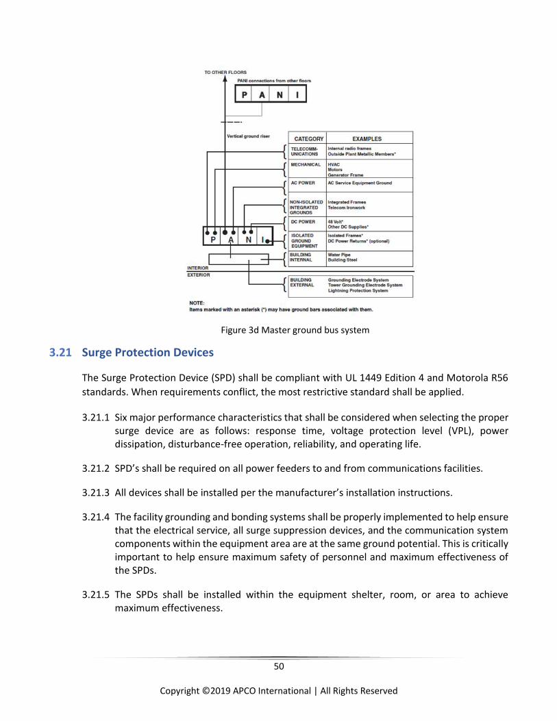
50
Copyright ©2019 APCO International | All Rights Reserved
Figure 3d Master ground bus system
3.21 Surge Protection Devices
The Surge Protection Device (SPD) shall be compliant with UL 1449 Edition 4 and Motorola R56
standards. When requirements conflict, the most restrictive standard shall be applied.
3.21.1 Six major performance characteristics that shall be considered when selecting the proper surge device are as follows: response time, voltage protection level (VPL), power dissipation, disturbance-free operation, reliability, and operating life.
3.21.2 SPD’s shall be required on all power feeders to and from communications facilities.
3.21.3 All devices shall be installed per the manufacturer’s installation instructions.
3.21.4 The facility grounding and bonding systems shall be properly implemented to help ensure that the electrical service, all surge suppression devices, and the communication system components within the equipment area are at the same ground potential. This is critically important to help ensure maximum safety of personnel and maximum effectiveness of the SPDs.
3.21.5 The SPDs shall be installed within the equipment shelter, room, or area to achieve maximum effectiveness.
51
Copyright ©2019 APCO International | All Rights Reserved
3.21.6 Installation at locations away from the equipment area shall NOT be performed, as it reduces the effectiveness of the SPD.
3.21.7 SPD’s shall be mounted as closely as possible to point of protection. Lead lengths shall be as short as possible and direct to avoid an increase in a suppressor’s response time and protection level.
3.21.8 Multiple surge protection devices shall be installed to reduce transient overvoltage. The SPD shall include a set of form “C” dry contacts, rated at a minimum of 250 VAC, and a minimum of 2.0 amperes, with a power factor of 1.0, for remote alarm reporting capability. This set of contacts shall operate when there is an input power failure or the integrity of any module has been compromised. This contact set shall be isolated from the AC power circuitry to safeguard the alarm circuit or reporting device should there be a catastrophic event. Connection to the remote monitoring contacts of the SPD shall utilize 0.34 mm2 (#22 AWG) or coarser conductors.
3.21.9 All sites shall have a Type 1 SPD that provides protection for the service entrance, and all branch panel locations within the same equipment room. If a generator and transfer switch is used, a Type 2 SPD shall be installed on the panel board before the transfer switch and a Type 1 SPD shall be installed on the panel board after the transfer switch.
3.21.10 Type 3 SPD’s shall be utilized when equipment is at greater than 10 conductor feet from the panel board.
3.22 Types 1, 2, and 3 Surge Protection Devices
The following requirements provide the unique requirements for Type 1, Type 2, and Type 3
Surge Protection Devices. These requirements are provided courtesy of Motorola Solutions, Inc.
(figure 3e).
3.22.1 Type 1
3.22.1.1 Type 1 SPD provides protection for the service entrance, and all branch panel locations within the same equipment room. The requirements are as follows:
3.22.1.2 The SPD shall be a permanently connected, one-port, or parallel configuration.
3.22.1.3 The suppression components shall be voltage-limiting type. Voltage switching components shall not be utilized as a suppression element in the SPD.
3.22.1.4 All suppression modules shall be installed from each phase conductor to the neutral conductor (L-N, Normal Mode).

52
Copyright ©2019 APCO International | All Rights Reserved
3.22.1.5 Suppression modules or devices of any type shall NOT be connected between any phase conductor and the equipment grounding conductor or ground (L-G, Common Mode Neutral to Ground).
3.22.1.6 The primary module(s) shall consist of a SAD module(s) providing 20KA per phase, per polarity, minimum energy absorption.
3.22.1.7 The secondary module(s) shall consist of a Metal Oxide Varistor (MOV) module(s), with sufficient energy handling capability to meet the maximum discharge current requirement of 160 kA per mode.
3.22.1.8 SPD shall be properly selected based on the operating voltage and number of phases of the circuits to be protected.
3.22.1.9 Each module or subassembly shall be modular in design to allow for easy field replacement.
3.22.1.10 The SPD shall use integral over-current protective devices and the SPD shall have a short circuit current rating of 25,000 amperes or larger, as defined by UL 1449, second edition, Section 39.
3.22.1.11 The SPD shall have a nominal discharge current of 10,000 amperes, as defined, and tested by IEEE (IEEE C62.45) waveform characteristics (Category C high 10 kA 6kV minimum) SPD tested in accordance with IEEE C62.45.
3.22.1.12 The SPD shall have a voltage protection level (at the nominal discharge current of 10,000 amperes) of 600 Vpk or less from each phase-to-neutral mode, when tested in accordance with IEEE C62.45-2002. Test points are measured using specified conductor size at a distance of 150 mm (6 in.) outside of the enclosure.
3.22.1.13 The SPD shall have a Suppressed Voltage Rating (SVR) of 330 Vpk, as determined by testing in accordance with the most recent edition of UL 1449.
3.22.1.14 The SPD shall have a maximum discharge current of 160 kA per mode, as tested in accordance with IEC 61643-1.
3.22.1.15 The enclosure rating of the SPD shall be NEMA 4.
3.22.1.16 The maximum dimensions of the enclosure shall be 406 mm × 406 mm × 228 mm (16 in. × 16 in. × 9 in.) for single-phase, 3W+G configurations, and 508 mm × 508 mm × 228 mm (20 in. × 20 in. × 9 in.) for three-phase wye.
3.22.1.17 4W+G configurations. The maximum weight of the SPD shall be 13.6kg (30 lb.), and 18 kg (40 lb.) respectively.
53
Copyright ©2019 APCO International | All Rights Reserved
3.22.1.18 The environmental parameters of the SPD shall be as follows: Operating temperature range: -40 °C to +65 °C ( -40F to 146F)
3.22.1.19 Storage temperature range: -40 °C to +65 °C (-40F to 146F)
3.22.1.20 Operating humidity range: 0-95%, non-condensing
3.22.1.21 Altitude range: -152.4 m to 4572 m (-500 ft. to +15,000 ft.)
3.22.1.22 Connection to the SPD shall be conducted with a wire range of 16 mm2 csa (#6 AWG) or coarser.
3.22.1.23 Per NFPA 70, the conductor size shall match the breaker size.
3.22.1.24 Each SPD shall have indicator lamps on or visible from the front of the device showing that power is applied and that the protection integrity has not been compromised.
3.22.1.25 The SPD shall be UL 1449, 2nd Edition listed, and tested to clause 7.10. A test report from a Nationally Recognized Testing Laboratory (NRTL), NAVLAP or A2LA, or a Certified UL client testing data laboratory detailing the procedures used, and the results obtained shall be made available.
3.22.2 Type 2
Type 2 SPDs provide protection for the service entrance locations within the same equipment room. The requirements are as follows:
3.22.2.1 The device shall consist of primary modules using MOV technology.
3.22.2.2 The SPD shall be a permanently connected, one-port or parallel configuration.
3.22.2.3 The suppression components shall be voltage-limiting type. Voltage switching components shall not be utilized as a suppression element in the SPD.
3.22.2.4 All suppression modules shall be installed from each phase conductor to the neutral conductor (L-N, Normal Mode).
3.22.2.5 Suppression modules or devices of any type shall NOT be connected between any phase conductor and the equipment grounding conductor or ground (L-G, Common Mode Neutral to Ground).
3.22.2.6 The primary module(s) shall consist of a Metal Oxide Varistor (MOV) module(s), with sufficient energy handling capability to meet the maximum discharge current requirement of 160kA per mode.
54
Copyright ©2019 APCO International | All Rights Reserved
3.22.2.7 The minimum pulse life or durability requirements and the voltage protection level shall be as specified in Table 7-4 for the respective Maximum Continuous Operating Voltage (MCOV) listed.
3.22.2.8 SPD shall be properly selected based on the operating voltage and number of phases of the circuits to be protected.
3.22.2.9 Each module or subassembly shall be modular in design to allow for easy field replacement.
3.22.2.10 The SPD shall use integral over-current protective devices, and the SPD shall have a short circuit current rating of 25,000 amperes or larger, as defined by the most recent version of UL 1449.
3.22.2.11 The SPD shall have a nominal discharge current of 10,000 amperes, as defined, and tested by IEEE C62.45.2-2002 waveform characteristics (Category C high 10 kA 6 kV minimum) SPD tested in accordance with IEEE C62.45-2002.
3.22.2.12 The SPD shall have a voltage protection level (at the nominal discharge current of 10,000 amperes) of 800Vpk or less from each phase-to-neutral mode, when tested in accordance with IEEE C62.45-2002. Test points are measured using specified conductor size at a distance of 150 mm (6 in.) outside of the enclosure.
3.22.2.13 The SPD shall have a Suppressed Voltage Rating (SVR) of 400 Vpk, as determined by testing in accordance with UL 1449, Second Edition and Section 34.
3.22.2.14 The enclosure rating of the SPD shall be NEMA 4. The maximum dimensions of the enclosure shall be 406 mm × 406 mm × 228 mm (16 in. × 16 in. × 9 in.) for single-phase, 3W+G configurations, and 508 mm × 508 mm × 228 mm (20 in. × 20 in. × 9 in.) for three-phase wye, 4W+G configurations. The maximum weight of the SPD shall be 13.6 kg (30 lb.), and 18 kg (40 lb.) respectively.
3.22.2.15 The environmental parameters of the SPD shall be as follows: Operating temperature range: -40 °C to +65 °C (-40F to 149F)
3.22.2.16 Storage temperature range: -40 °C to +65 °C (-40f to 146F)
3.22.2.17 Operating humidity range: 0-95%, non-condensing
3.22.2.18 Altitude range: -152.4 m to 4572 m (-500 ft. to +15,000 ft.)
3.22.2.19 Connection to the SPD shall be conducted with a wire range of 16 mm2 csa (#6 AWG) per NFPA, the conductor size shall match the breaker size.

55
Copyright ©2019 APCO International | All Rights Reserved
3.22.2.20 Each SPD shall have indicator lamps on or visible from the front of the device showing that power is applied and that the protection integrity has not been compromised.
3.22.2.21 The SPD shall be UL 1449, 2nd Edition listed, and tested to clause 7.10. A test report from a Nationally Recognized Testing Laboratory (NRTL), NAVLAP or A2LA, or a Certified UL client testing data laboratory detailing the procedures used, and the results obtained shall be made upon request.
3.22.3 Type 3
Individual equipment SPDs are available in many varieties (Figure 7e). These may be wire-
in receptacle outlet replacement types, plug-in adapters, or receptacle outlet panels or
strips. General requirements are as follows:
3.22.3.1 All individual equipment devices shall provide Normal Mode (L-N) circuit protection.
3.22.3.2 Common Mode (L-G) circuit protection shall NOT be permitted.
3.22.3.3 Individual devices with the plug manufactured as a combined part of the device shall be designed to be plugged into a single simplex receptacle outlet and shall incorporate a single simplex receptacle outlet for the load connection. Individual plug-in units with a duplex receptacle outlet shall NOT be used.
3.22.3.4 Multi-receptacle outlet strip devices, if used, shall incorporate an independent ground point on the exterior of the device. This attachment point or stud shall be suitable for attachment of a lug sized for a 16 mm2 csa (#6 AWG) conductor.
3.22.3.5 Multi-receptacle device housings, if used, shall be metallic and shall be provided with mounting ears, tabs, or brackets. Devices may be suitable for standard EIA 483 mm (19 in.) rack mounting.
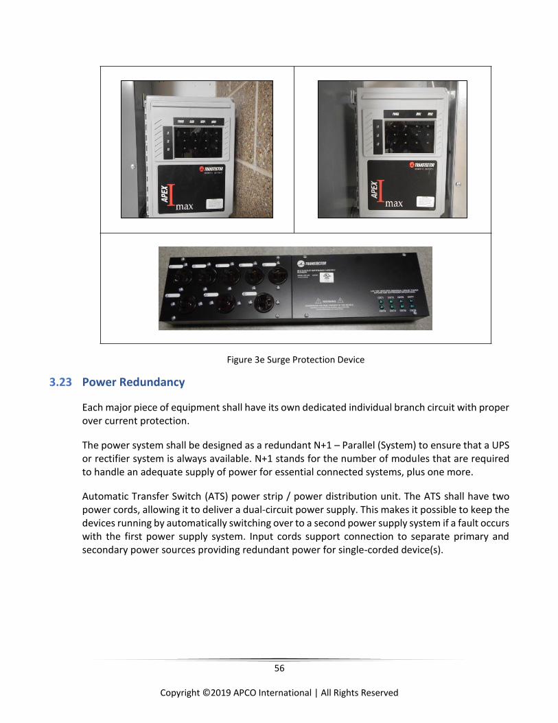
56
Copyright ©2019 APCO International | All Rights Reserved
Figure 3e Surge Protection Device
3.23 Power Redundancy
Each major piece of equipment shall have its own dedicated individual branch circuit with proper over current protection.
The power system shall be designed as a redundant N+1 – Parallel (System) to ensure that a UPS or rectifier system is always available. N+1 stands for the number of modules that are required to handle an adequate supply of power for essential connected systems, plus one more.
Automatic Transfer Switch (ATS) power strip / power distribution unit. The ATS shall have two power cords, allowing it to deliver a dual-circuit power supply. This makes it possible to keep the devices running by automatically switching over to a second power supply system if a fault occurs with the first power supply system. Input cords support connection to separate primary and secondary power sources providing redundant power for single-corded device(s).
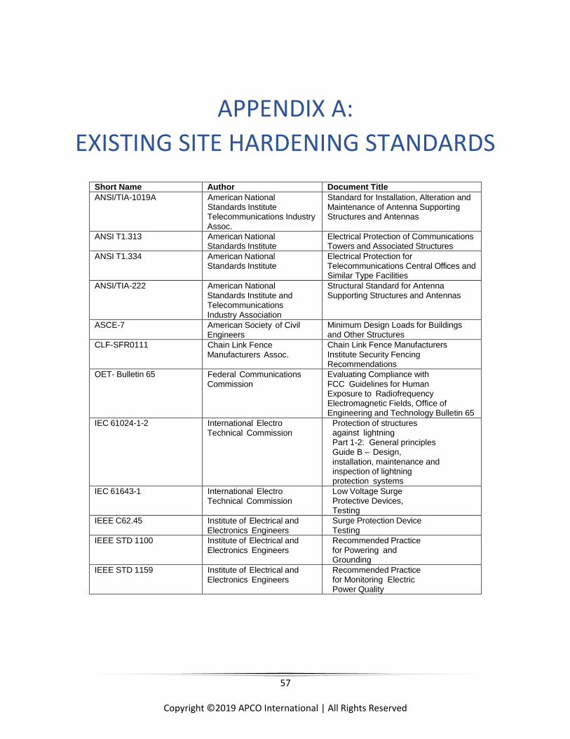
57
Copyright ©2019 APCO International | All Rights Reserved
APPENDIX A:
EXISTING SITE HARDENING STANDARDS
Short Name Author Document Title
ANSI/TIA-1019A American National Standards Institute Telecommunications Industry Assoc.
Standard for Installation, Alteration and Maintenance of Antenna Supporting Structures and Antennas
ANSI T1.313 American National Standards Institute
Electrical Protection of Communications Towers and Associated Structures
ANSI T1.334 American National Standards Institute
Electrical Protection for Telecommunications Central Offices and Similar Type Facilities
ANSI/TIA-222 American National Standards Institute and Telecommunications Industry Association
Structural Standard for Antenna Supporting Structures and Antennas
ASCE-7 American Society of Civil Engineers
Minimum Design Loads for Buildings and Other Structures
CLF-SFR0111 Chain Link Fence Manufacturers Assoc.
Chain Link Fence Manufacturers Institute Security Fencing Recommendations
OET- Bulletin 65 Federal Communications Commission
Evaluating Compliance with FCC Guidelines for Human Exposure to Radiofrequency Electromagnetic Fields, Office of Engineering and Technology Bulletin 65
IEC 61024-1-2 International Electro Technical Commission
Protection of structures against lightning Part 1-2: General principles Guide B – Design, installation, maintenance and inspection of lightning protection systems
IEC 61643-1 International Electro Technical Commission
Low Voltage Surge Protective Devices, Testing
IEEE C62.45 Institute of Electrical and Electronics Engineers
Surge Protection Device Testing
IEEE STD 1100 Institute of Electrical and Electronics Engineers
Recommended Practice for Powering and Grounding
IEEE STD 1159 Institute of Electrical and Electronics Engineers
Recommended Practice for Monitoring Electric Power Quality
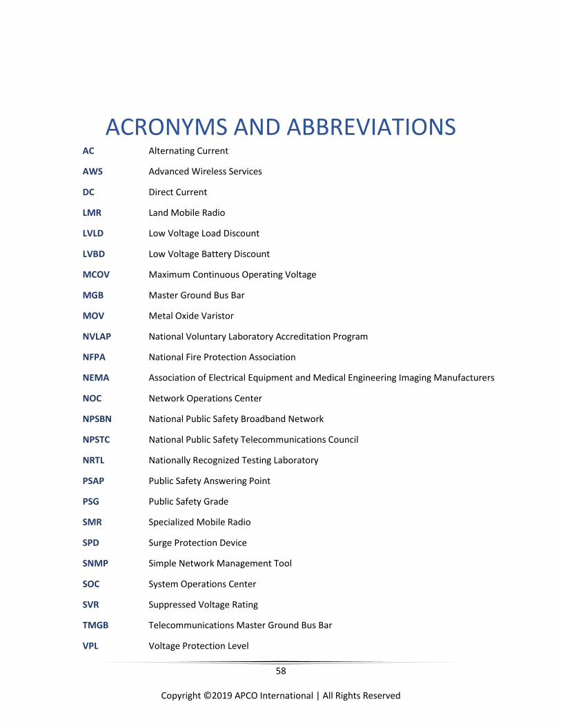
58
Copyright ©2019 APCO International | All Rights Reserved
ACRONYMS AND ABBREVIATIONS AC Alternating Current
AWS Advanced Wireless Services
DC Direct Current
LMR Land Mobile Radio
LVLD Low Voltage Load Discount
LVBD Low Voltage Battery Discount
MCOV Maximum Continuous Operating Voltage
MGB Master Ground Bus Bar
MOV Metal Oxide Varistor
NVLAP National Voluntary Laboratory Accreditation Program
NFPA National Fire Protection Association
NEMA Association of Electrical Equipment and Medical Engineering Imaging Manufacturers
NOC Network Operations Center
NPSBN National Public Safety Broadband Network
NPSTC National Public Safety Telecommunications Council
NRTL Nationally Recognized Testing Laboratory
PSAP Public Safety Answering Point
PSG Public Safety Grade
SMR Specialized Mobile Radio
SPD Surge Protection Device
SNMP Simple Network Management Tool
SOC System Operations Center
SVR Suppressed Voltage Rating
TMGB Telecommunications Master Ground Bus Bar
VPL Voltage Protection Level

59
Copyright ©2019 APCO International | All Rights Reserved
NOTES

60
Copyright ©2019 APCO International | All Rights Reserved
APCO American National Standards
APCO American National Standards (ANS) are voluntary consensus standards. Use of any APCO standard is
voluntary. All standards are subject to change. APCO ANS are required to be reviewed no later than every five
years. The designation of an APCO standard should be reviewed to ensure you have the latest edition of an APCO
standard, for example:
APCO ANS 3.101.1-2007 = 1- Operations, 2- Technical, 3-Training
APCO ANS 3.101.1-2007 = Unique number identifying the standard
APCO ANS 3.101.1-2007 = The edition of the standard, which will increase after each revision
APCO ANS 3.101.1-2007 = The year the standard was approved and published, which may change after each
revision.
The latest edition of an APCO standard cancels and replaces older versions of the APCO standard. Comments
regarding APCO standards are accepted any time and can be submitted to [email protected], if the
comment includes a recommended change, it is requested to accompany the change with supporting material. If
you have a question regarding any portion of the standard, including interpretation, APCO will respond to your
request following its policies and procedures. ANSI does not interpret APCO standards; they will forward the
request to APCO.
APCO International adheres to ANSI's Patent Policy. Neither APCO nor ANSI is responsible for identifying patents
for which a license may be required by an American National Standard or for conducting inquiries into the legal
validity or scope of any patents brought to their attention.
No position is taken with respect to the existence or validity of any patent rights within this standard. APCO is the
sole entity that may authorize the use of trademarks, certification marks, or other designations to indicate
compliance with this standard.
Permission must be obtained to reproduce any portion of this standard and can be obtained by contacting APCO
International's Communications Center & 9-1-1 Services Department. Requests for information, interpretations,
and/or comments on any APCO standards should be submitted in writing addressed to:
APCO Standards Program Manager, Communications Center & 9-1-1 Services APCO International 351 N. Williamson Blvd Daytona Beach, FL 32114 USA [email protected]

61
Copyright ©2019 APCO International | All Rights Reserved