Embed Size (px)
Citation preview
CHAPTER 23 ALTERNATING CURRENT
CIRCUITS
ANSWERS TO FOCUS ON CONCEPTS QUESTIONS
1. (d) According to 2rms
/P V R (Equation 20.15c), the average power is proportional to the
square of the rms voltage. Tripling the voltage causes the power to increase by a factor of
32 = 9.
2. Irms = 1.9 A
3. (b) The current Irms through a capacitor depends inversely on the capacitive reactance XC,
as expressed by the relation Irms = Vrms/ XC (Equation 23.1). The capacitive reactance
becomes infinitely large as the frequency goes to zero (see Equation 23.2), so the current
goes to zero.
4. (e) According to C1/ 2X f C (Equation 23.2) and
L2X f L (Equation 23.4),
doubling the frequency f causes XC to decrease by a factor of 2 and XL to increase by a
factor of 2.
5. Irms = 1.3 A
6. (a) The component of the phasor along the vertical axis is V0 sin 2 f t (see the drawing that
accompanies this problem), which is the instantaneous value of the voltage.
7. (b) The instantaneous value of the voltage is the component of the phasor that lies along the
vertical axis (see Sections 23.1 and 23.2). This vertical component is greatest in B and least
in A, so the ranking is (largest to smallest) B, C, A.
8. (d) In a resistor the voltage and current are in phase. This means that the two phasors are
colinear.
9. (c) Power is dissipated by the resistor, as discussed in Section 20.5. On the other hand, the
average power dissipated by a capacitor is zero (see Section 23.1).
10. Irms = 2.00 A
11. (a) When the rms voltage across the inductor is greater than that across the capacitor, the
voltage across the RCL combination leads the current (see Section 23.3).
1178 ALTERNATING CURRENT CIRCUITS
12. (d) Since Irms= Vrms/Z (Equation 23.6), the current is a maximum when the impedance Z is a
minimum. The impedance is 22
L CZ R X X (Equation 23.7), and it has a
minimum value when XC = XL = 50 .
13. (c) The inductor has a very small reactance at low frequencies and behaves as if it were
replaced by a wire with no resistance. Therefore, the circuit behaves as two resistors, R1 and
R2, connected in parallel. The inductor has a very large reactance at high frequencies and
behaves as if it were cut out of the circuit, leaving a gap in the connecting wires. The circuit
behaves as a single resistance R2 connected across the generator. The situation at low
frequency gives rise to the largest possible current, because the effective resistance of the
parallel combination is smaller than the resistance R2.
14. (a) The capacitor has a very small reactance at high frequencies and behaves as if it were
replaced by a wire with no resistance. Therefore, the circuit behaves as two resistors, R1 and
R2, connected in parallel. The capacitor has a very large reactance at low frequencies and
behaves as if it were cut out of the circuit, leaving a gap in the connecting wires. Therefore,
the circuit behaves as a single resistor R1 connected across the generator. The situation at
high frequencies gives rise to the largest possible current, because the effective resistance of
the parallel combination is smaller than the resistance R1.
15. (e) At low frequencies, the capacitor has a very large reactance. In the series circuit, this
large reactance gives rise to a large impedance and, hence, a small current. The parallel
circuit has the larger current, because current can flow through the inductor, which has a
small reactance at low frequencies.
16. (b) The resonant frequency f0 is given by 0
1
2f
LC (Equation 23.10). It depends only
on C and L, and not on R.
17. f0 = 1.3 103 Hz
18. (d) The resonant frequency f0 is given by 0
1
2f
LC (Equation 23.10). When a second
capacitor is added in parallel, the equivalent capacitance increases (see Section 20.12).
Therefore, the resonant frequency decreases.

Chapter 23 Problems 1179
CHAPTER 23 ALTERNATING
CURRENT CIRCUITS
PROBLEMS
1. SSM REASONING As the frequency f of the generator increases, the capacitive
reactance XC of the capacitor decreases, according to C
1
2X
f C (Equation 23.2), where
C is the capacitance of the capacitor. The decreasing capacitive reactance leads to an
increasing rms current Irms, as we see from rmsrms
C
VI
X (Equation 23.1), where Vrms is the
constant rms voltage across the capacitor. We know that Vrms is constant, because it is equal
to the constant rms generator voltage. The fuse is connected in series with the capacitor, so
both have the same current Irms. We will use Equations 23.1 and 23.2 to determine the
frequency f at which the rms current is 15.0 A.
SOLUTION Solving Equation 23.2 for f, we obtain
C
1
2f
C X (1)
In terms of the rms current and voltage, Equation 23.1 gives the capacitive reactance as
rmsC
rms
VX
I . Substituting this relation into Equation (1) yields
rms
6C rmsrms
rms
1 1 15.0 A9470 Hz
2 2 2 63.0 10 F 4.00 V2
If
C X CVVC
I
2. REASONING When two capacitors of capacitance C are connected in parallel, their
equivalent capacitance CP is given by P
2C C C C (Equation 20.18). We will find the
capacitive reactance XC of the equivalent capacitance from CP
1
2X
f C (Equation 23.2).
Because the capacitors are the only devices connected to the generator, the rms voltage Vrms
across the capacitors is equal to the rms voltage of the generator. Therefore, the capacitive
reactance XC is related to the rms voltage of the generator and the rms current Irms in the
circuit by rms rms C
V I X (Equation 23.1).
1180 ALTERNATING CURRENT CIRCUITS
SOLUTION Substituting CP = 2C into C
P
1
2X
f C (Equation 23.2) and solving for C,
we obtain
C
P C
1 1 1 1 or
2 2 2 4 4X C
f C f C fC fX (1)
Solving rms rms C
V I X (Equation 23.1) for XC yields rmsC
rms
VX
I . Substituting this result
into Equation (1), we obtain
7rms
rmsC rms
rms
1 1 0.16 A 8.7 10 F
4 4 4 610 Hz 24 V4
IC
VfX fVf
I
3. REASONING The reactance XC of a capacitor is given as C
1
2X
f C (Equation 23.2),
where f is the frequency of the ac current and C is the capacitance of the capacitor. We note
that XC is inversely proportional to f for a given value of C. Therefore, we will be able to
solve this problem by applying Equation 23.2 twice, once for each value of the frequency
and each time with the same value of the capacitance.
SOLUTION Applying Equation 23.2 for each value of the frequency, we obtain
C, 870 C, 460870 460
1 1 and
2 2X X
f C f C
Dividing the equation on the left by the equation on the right and noting that the unknown
capacitance C is eliminated algebraically, we find that
C, 870 870 460
C, 460 870
460
1
2
1
2
X f C f
X f
f C
Solving for the reactance at a frequency of 870 Hz gives
460C, 870 C, 460
870
460 Hz68 36
870 Hz
fX X
f
4. REASONING The rms voltage Vrms and current Irms in a capacitor are related according to
rms rms CV I X (Equation 23.1). XC is the capacitive reactance C
1
2X
f C
(Equation 23.2), where f is the frequency in hertz (Hz) and C is the capacitance of the
capacitor. We will apply these equations to the capacitor when connected to each of the
Chapter 23 Problems 1181
generators. Although we are not given a value for the capacitance, we will see that it is
eliminated algebraically from the calculation.
SOLUTION Substituting Equation 23.2 for the capacitive reactance into Equation 23.1, we
obtain
rms rms C rms
1
2V I X I
f C
(1)
Applying Equation (1) to the capacitor when connected to generator 1 and generator 2, we
have
rms rms rms rms1 1 2 21 2
1 1 and
2 2V I V I
f C f C
Dividing the equation on the right by the equation on the left, we note that the capacitance C
is eliminated algebraically and find that
rms rms 2 rms 1 rms 12 2 2 2
rms rms 1 2 rms 2 rms1 1 1 1
/ 2 2
/ 2 2
V I f C I f C I f
V I f C f C I f I
(2)
Solving Equation (2) for the voltage of the second generator gives
3 3rms rms 11 2
rms 3 322 rms 1
2.0 V 85 10 A 3.4 10 Hz3.3 V
5.0 10 Hz 35 10 A
V I fV
f I
5. SSM REASONING The rms current in a capacitor is Irms
= Vrms
/XC, according to
Equation 23.1. The capacitive reactance is XC = 1/(2 f C), according to Equation 23.2. For
the first capacitor, we use C = C1 in these expressions. For the two capacitors in parallel, we
use C = CP, where C
P is the equivalent capacitance from Equation 20.18 (C
P = C
1 + C
2).
Taking the difference between the currents and using the given data, we can obtain the
desired value for C2. The capacitance C
1 is unknown, but it will be eliminated algebraically
from the calculation.
SOLUTION Using Equations 23.1 and 23.2, we find that the current in a capacitor is
IV
X
V
f CV f C
rms
rms
C
rms
rms
1 22
/ b g
Applying this result to the first capacitor and the parallel combination of the two capacitors,
we obtain
I V f C I V f C C1 rms
Single capacitor
Combination rms
Parallel combination
and 2 21 1 2
c h
Subtracting I
1 from I
Combination, reveals that
1182 ALTERNATING CURRENT CIRCUITS
I I V f C C V f C V f CCombination 1 rms rms rms
2 2 21 2 1 2
c h Solving for C
2 gives
CI I
V f2
6
2
0 18
2 4402 7 10
Combination 1
rms
A
24 V Hz F
..b g b g
6. REASONING The rms current in the circuit is given by Irms
= Vrms
/XC (Equation 23.1),
where Vrms
is the rms voltage of the generator, and XC = 1/(2 f C) is the capacitive
reactance (see Equation 23.2). For a given voltage, smaller reactances lead to greater
currents.
When two capacitors are connected in parallel, the equivalent capacitance CP is given by
CP = C
1 + C
2 (Equation 20.18), where C
1 and C
2 are the individual capacitances. Therefore,
CP is greater than either C
1 or C
2. Thus, when the capacitors are connected in parallel, the
greater capacitance leads to a smaller reactance (C is in the denominator in Equation 23.2),
which in turn leads to a greater current. As a result, the current delivered by the generator
increases when the second capacitor is connected in parallel with the first capacitor.
The capacitance of a parallel plate capacitor is given by C = 0A/d (Equation 19.10), where
is the dielectric constant of the material between the plates, 0 is the permittivity of free
space, A is the area of each plate, and d is the separation between the plates. When the
capacitor is empty, = 1, so that C = Cempty
. Thus, the capacitance increases when the
dielectric material is inserted.
SOLUTION Using Equation 23.1 to express the current as Irms
= Vrms
/XC and Equation 23.2
to express the capacitive reactance as XC = 1/(2 f C), we have for the current that
IV
X
V
f CV f C
rms
rms
C
rms
rms
1 22
/ b g
Applying this result to the case where the empty capacitor C
1 is connected alone to the
generator and to the case where the “full” capacitor C2 (which contains the dielectric
material) is connected in parallel with C1, we obtain
1 1 2
1, rms rms 1 P, rms rms P
alone and in parallel
2 and 2
C C C
I V f C I V f C
Dividing the two expressions gives
I
I
V f C
V f C
C
C
P PP, rms
1, rms
rms
rms
2
21 1

Chapter 23 Problems 1183
According to Equation 20.18, the equivalent capacitance of the two capacitors in parallel is
CP = C
1 + C
2, so that the result for the current ratio becomes
I
I
C C
C
C
C
P, rms
1, rms
1 2
1
2
1
1
Since the capacitance of a filled capacitor is given by Equation 19.10 as C =
0A/d, we find
that
I
I
A d
A d
P, rms
1, rms
1 10
0
/
/
Solving for IP, rms
gives
I IP, rms 1, rms
A A 1 0 22 1 4 2 1 1b gb gb g. . .
7. REASONING The capacitance C is related to the capacitive reactance XC and the
frequency f via Equation 23.2 as C = 1/(2fXC). The capacitive reactance, in turn is related
to the rms-voltage Vrms
and the rms-current Irms
by XC = V
rms/I
rms (see Equation 23.1). Thus,
the capacitance can be written as C = Irms
/(2fVrms
). The magnitude of the maximum charge
q on one plate of the capacitor is, from Equation 19.8, the product of the capacitance C and
the peak voltage V.
SOLUTION
a. Recall that the rms-voltage Vrms
is related to the peak voltage V by Vrms
= V
2. The
capacitance is, then,
CI
f V F
HGIKJ rms
rms2
A
2 HzV
2
F
3 0
750140
6 4 10 6.
.
b g
b. The maximum charge on one plate of the capacitor is
q CV 6 4 10 140 9 0 106 4. .F V Cc hb g
8. REASONING AND SOLUTION Equations 23.1 and 23.2 indicate that the rms current in a
capacitor is I V X /C
, where V is the rms voltage and X f CC1 2/ b g. Therefore, the
current is I V f C 2 . For a single capacitor C C1, and we have
I V f C 2
1
For two capacitors in series, Equation 20.19 indicates that the equivalent capacitance can be

1184 ALTERNATING CURRENT CIRCUITS
obtained from C C C–1 –1 –1 1 2
, which can be solved to show that C C C C C 1 2 1 2
/c h.
The total series current is, then,
I V f C V fC C
C Cseries
FHG
IKJ2 2 1 2
1 2
The series current is one-third of the current I. It follows, therefore, that
I
I
V fC C
C C
V f C
C
C C
C
C
series or
FHG
IKJ
2
2
1
32
1 2
1 2
1
2
1 2
1
2
For two capacitors in parallel, Equation 20.18 indicates that the equivalent capacitance is
C C C 1 2
. The total current in this case is
I V f C V f C Cparallel
2 21 2
c h The ratio of I
parallel to the current I in the single capacitor is
I
I
V f C C
V f C
C C
C
C
C
parallel 3
2
2
21 1
1
2
1 2
1
1 2
1
2
1
c h
9. SSM REASONING The rms current can be calculated from Equation 23.3,
I V Xrms rms L
/ , provided that the inductive reactance is obtained first. Then the peak value
of the current I0 supplied by the generator can be calculated from the rms current I
rms by
using Equation 20.12, I I0
2rms
.
SOLUTION At the frequency of f 620 Hz , we find, using Equations 23.4 and 23.3, that
X f LL
Hz)(8.2 2 2 620 10 ( –3 H) = 32
IV
Xrms
rms
L
10.0 V
32 A
0 31.
Therefore, from Equation 20.12, we find that the peak value I
0 of the current supplied by the
generator must be
I I0 2 2 0.31 A 0.44 A
rms b g
10. REASONING The rms voltage Vrms and current Irms in an inductor are related according to
rms rms LV I X (Equation 23.3). XL is the capacitive reactance L 2X f L
(Equation 23.4), where f is the frequency in hertz (Hz) and L is the inductance of the
inductor. Since we have values for Vrms, f, and L, we can use these equations to calculate
the unknown current Irms.
Chapter 23 Problems 1185
SOLUTION Substituting Equation 23.4 for the inductive reactance into Equation 23.3, we
obtain
rms rms L rms2V I X I f L (1)
Solving Equation (1) for Irms, we find that
rmsrms rms rms
55 V2 or 0.17 A
2 2 650 Hz 0.080 H
VV I f L I
f L
11. REASONING The rms voltage Vrms across the inductor is given by
rms rms LV I X (Equation 23.3), where Irms is the rms current in the circuit, and XL is the
inductive reactance. The inductor is the only circuit element connected to the generator, so
the rms voltage across the inductor is equal to the rms generator voltage: Vrms = 15.0 V.
SOLUTION Solving Equation 23.3 for XL, we obtain
rmsL
rms
15.0 V24.6
0.610 A
VX
I
12. REASONING The inductance L of the inductor determines its inductive reactance XL
according to L
2X fL (Equation 23.4), where f is the frequency of the generator. When
the inductor is connected to the terminals of the generator, the rms voltage Vrms of the
generator drives an rms current Irms that depends upon the inductive reactance via
rmsL
rms
VX
I (Equation 23.3). We note that the generator frequency is given in kHz, where
1 kHz = 103 Hz, and the rms current is given in mA, where 1 mA = 10−3 A.
SOLUTION Solving L
2X fL (Equation 23.4) for L yields
L
2
XL
f (2)
Substituting rmsL
rms
VX
I (Equation 23.3) into Equation (1), we find that
rms
rms rmsL
3 3rms
39 V0.020 H
2 2 2 2 7.5 10 Hz 42 10 A
V
I VXL
f f fI
1186 ALTERNATING CURRENT CIRCUITS
13. REASONING Since the capacitor and the inductor are connected in parallel, the voltage
across each of these elements is the same or V VL C . Using Equations 23.3 and 23.1,
respectively, this becomes I X I Xrms L rms C
. Since the currents in the inductor and
capacitor are equal, this relation simplifies to X XL C . Therefore, we can find the value
of the inductance by equating the expressions (Equations 23.4 and 23.2) for the inductive
reactance and the capacitive reactance, and solving for L.
SOLUTION Since X XL C , we have
21
2
f L
f C
Therefore, the value of the inductance is
Lf C
1
4
1
4 60.0 100 176
2 2 2 ( ( H = 176 mH
Hz) 40.0 F)2 –6.
14. REASONING The current in L1 is given by Equation 23.3 as I
rms = V
rms/X
L, where
XL = 2 f L
1 (Equation 23.4) is the inductive reactance of L
1. This current does not depend in
any way on L2 and exists whether or not L
2 is present.
The current delivered to the parallel combination is the sum of the currents delivered to each
inductance and is, therefore, greater than either individual current. The current in L2 is given
by Irms
= Vrms
/XL (Equation 23.3), where X
L = 2 f L
2 is the inductive reactance of L
2
according to Equation 23.4. This current does not depend in any way on L1 and exists
whether or not L1 is present.
SOLUTION Using Equation 23.3 to express the current as Irms
= Vrms
/XL and Equation 23.4
to express the inductive reactance as XL = 2 f L, we have for the current that
IV
X
V
f Lrms
rms
L
rms 2
Applying this result to the case where L
1 or L
2 is connected alone to the generator, we obtain
IV
X
V
f LI
V
X
V
f L
L L
1, rms
rms
L
rms
alone
2, rms
rms
L
rms
alone1 2
and 2 2
1 2
The current delivered to L
1 alone is
IV
f L1, rms
rms V
Hz H A
2
240
2 2200 6 0 102 9
13 b gc h.
.
Chapter 23 Problems 1187
The current delivered to the parallel combination of L1 and L
2 is the sum of that delivered
individually to each inductor and is
I I IV
f L
V
f L
V
f L LP, rms 1, rms 2, rms
rms rms rms
V
Hz H H A
FHG
IKJ
FHG
IKJ
2 2 2
1 1
240
2 2200
1
6 0 10
1
9 0 104 8
1 2 1 2
3 3
b g . ..
15. SSM REASONING
a. The inductive reactance XL depends on the frequency f of the current and the inductance
L through the relation XL = 2 f L ( Equation 23.4). This equation can be used directly to
find the frequency of the current.
b. The capacitive reactance XC depends on the frequency f of the current and the capacitance
C through the relation XC = 1/(2 f C ) ( Equation 23.2). By setting XC = XL as specified in
the problem statement, the capacitance can be found.
c. Since the inductive reactance is directly proportional to the frequency, tripling the
frequency triples the inductive reactance.
d. The capacitive reactance is inversely proportional to the frequency, so tripling the
frequency reduces the capacitive reactance by a factor of one-third.
SOLUTION a. The frequency of the current is
34L
3
2.10 101.11 10 Hz
2 2 30.0 10 H
Xf
L
(23.4)
b. The capacitance is
9
4 3C
1 16.83 10 F
2 2 1.11 10 Hz 2.10 10C
f X
(23.2)
c. Since XL = 2 f L , tripling the frequency f causes XL to also triple:
3 3L
= 3 2.10 10 = 6.30 10X
d. Since XC = 1/(2 f C ) , tripling the frequency f causes XC to decrease by a factor of 3:
3 21C 3
= 2.10 10 = 7.00 10X
1188 ALTERNATING CURRENT CIRCUITS
16. REASONING AND SOLUTION Equations 23.3 and 23.4 indicate that the rms current in a
single inductance L1 is I
1 = V/X
L1, where V is the rms voltage and X
L1 = 2fL
1. Therefore,
the current is I V f L1 1
2 / c h. Similarly, the current in the second inductor connected
across the terminals of the generator is I V f L2 2
2 / c h. The total current delivered by
the generator is the sum of these two values:
I I IV
f L
V
f Ltotal
1 2
1 22 2
But this same total current is delivered to the single inductance L, so it also follows that
I V f Ltotal
/ 2b g. Equating the two expressions for Itotal
shows that
V
f L
V
f L
V
f L L L L2 2 2
1 1 1
1 2 1 2
or
Using this result, we determine the value of L as follows:
1 1 1 0 030 0 060
0 030 0 0601 2
1 2
1 2L L L
LL L
L L
or
H H
H H0 020 H
. .
. .
b gb g.
17. SSM REASONING The voltage supplied by the generator can be found from Equation
23.6, V I Zrms rms
. The value of Irms
is given in the problem statement, so we must obtain
the impedance of the circuit.
SOLUTION The impedance of the circuit is, according to Equation 23.7,
Z R X X 2 2 2275 3 60 10( – ) .L C
2 2( ) (648 – 415 )
The rms voltage of the generator is
V I Zrms rms
A ) = 83.9 V ( . )( .0 233 3 60 102
18. REASONING As discussed in Section 23.3, the power factor is
22
L C
cosR
R X X
, where R is the resistance, XL is the inductive reactance, and XC
is the capacitive reactance of the circuit. The inductive reactance is given by L 2X f L
(Equation 23.4), where f is the frequency in hertz (Hz) and L is the inductance. The
capacitive reactance is given by C
1
2X
f C (Equation 23.2), where C is the capacitance.
Chapter 23 Problems 1189
SOLUTION Using Equation 23.4 and Equation 23.2 to substitute for the reactances, we
find that the power factor is
2 222L C
2
2 3
6
cos
12
2
47.0
147.0 2 2550 Hz 4.00 10 H
2 2550 Hz 2.00 10 F
0.819
R R
R X XR f L
f C
19. SSM REASONING We can use the equations for a series RCL circuit to solve this
problem provided that we set C 0 X since there is no capacitor in the circuit. The
current in the circuit can be found from Equation 23.6, rms rms
V I Z , once the impedance of
the circuit has been obtained. Equation 23.8, L C
tan ( ) /X X R , can then be used (with
C0X ) to find the phase angle between the current and the voltage.
SOLUTION The inductive reactance is (Equation 23.4)
L2 2 106 Hz 0.200 H 133X f L
The impedance of the circuit is
2 2 2 2 2 2L C L
( – ) (215 ) (133 ) 253 Z R X X R X
a. The current through each circuit element is, using Equation 23.6,
rmsrms
234 V0.925 A
Z 253
VI
b. The phase angle between the current and the voltage is, according to Equation 23.8 (with
C0X ),
–1L C L 133 tan = 0.619 or tan (0.619) 31.8
215
X X X
R R
1190 ALTERNATING CURRENT CIRCUITS
20. REASONING The phase angle is given by tan = (XL – X
C)/R (Equation 23.8). When a
series circuit contains only a resistor and a capacitor, the inductive reactance XL is zero, and
the phase angle is negative, signifying that the current leads the voltage of the generator.
The impedance is given by Equation 23.7 with XL = 0 , or Z R X 2
C
2 . Since the
phase angle and the impedance Z are given, we can use these relations to find the
resistance R and XC.
SOLUTION Since the phase angle is negative, we can conclude that only a resistor and a
capacitor are present. Using Equations 23.8, then, we have
tan tan . .
X
RX R RC
C or 75 0 3 73b g
According to Equation 23.7, the impedance is
Z R X 192 2C
2
Substituting XC = 3.73R into this expression for Z gives
192 3 73 192
192
14 949 7
2 2 2
2
R R
R
.
..
b g b g
b g
= 14.9 R or 14.9 R2 2
Using the fact that X
C = 3.73 R, we obtain
X
C = 3.73 (49.7 ) = 185
21. REASONING For a series RCL circuit the total impedance Z and the phase angle are
given by
22 L C
L C (23.7) tan (23.8)
X XZ R X X
R
where R is the resistance, XL is the inductive reactance, and XC is the capacitive reactance.
In the present case, there is no capacitance, so that C
0 X . Therefore, these equations
simplify to the following:
2 2 LL
(1) tan (2)X
Z R XR
We are given neither R nor XL. However, we do know the current and voltage when only
the resistor is connected and can determine R from these values using rms
rms
VR
I
(Equation 20.14). In addition, we know the current and voltage when only the inductor is
Chapter 23 Problems 1191
connected and can determine XL from these values using rmsL
rms
VX
I (Equation 23.3). Since
the generator frequency is fixed, this value for XL also applies for the series combination of
the resistor and the inductor.
SOLUTION With only the resistor connected, Equation 20.14 indicates that the resistance
is
rms
rms
112 V224
0.500 A
VR
I
With only the inductor connected, Equation 23.3 indicates that the inductive reactance is
2rmsL
rms
112 V2.80 10
0.400 A
VX
I
a. Using these values for R and XL in Equations (1) and (2), we find that the impedance is
222 2 2
L 224 2.80 10 359 Z R X
b. The phase angle between the current and the voltage of the generator is
21 1L L 2.80 10
tan or tan tan 51.3224
X X
R R
22. REASONING Since, on the average, only the resistor consumes power, the average power
dissipated in the circuit is 2rms
P I R (Equation 20.15b), where Irms is the rms current and R
is the resistance. The current is related to the voltage V of the generator and the impedance Z
of the circuit by rms rms
/I V Z (Equation 23.6). Thus, the average power can be written as
2 2/P V R Z . The impedance of the circuit is (see Equation 23.7) 22
L CZ R X X
2 2C
R X , since there is no inductor in the circuit. Therefore, the expression for the
average power becomes 2 2
2 2 2C
V R V RP
Z R X
SOLUTION The capacitive reactance is
C 6
1 12400
2 2 60.0 Hz 1.1 10 FX
f C
(23.2)
The average power dissipated is
1192 ALTERNATING CURRENT CIRCUITS
22
2 2 2 2C
120 V 2700 3.0 W
2700 2400
V RP
R X
23. REASONING From Figure 23.11 we see that V V V V0
2 2
L C R
2c h . Since VL = 0 V
(L = 0 H), and we know V0 and V
R, we can use this equation to find V
C.
SOLUTION Solving the equation above for VC gives
V V VC R
2 V V V 0
2 2 245 24 38b g b g
24. REASONING The rms current Irms in the circuit in part c of the drawing is equal to the
rms voltage Vrms divided by the impedance Z or
rmsrms
VI
Z (Equation 23.6). The impedance
Z of a series RC circuit is given by Equation 23.7 with XL = 0 , since there is no
inductance in the circuit; 2 2C
Z R X The resistance R is known and the capacitive
reactance XC can be obtained from the relation XC = 1/(2 f C) (Equation 23.2), where C is
the capacitance and f is the frequency. The capacitance, however, is related to the time
constant of the circuit in part a of the drawing. The time constant of an RC circuit is the
time for the capacitor to lose 63.2% of its initial charge (see the discussion in Section
20.13), and it is equal to the product of the resistance R and the capacitance C; RC
(Equation 20.21).
SOLUTION Substituting 2 2C
Z R X into rmsrms
VI
Z gives
rms rmsrms 2 2
C
V VI
Z R X
(1)
Substituting XC = 1/(2 f C) (Equation 23.2) into Equation (1) allows us to write the rms
current in the circuit in part c of the drawing as follows:
Substituting C = R (Equation 20.21) into Equation (1), we arrive at an expression for the
rms current:
rms rmsrms 2 2 2
2C 1
2
V VI
R XR
f C

Chapter 23 Problems 1193
25. SSM REASONING We can use the equations for a series RCL circuit to solve this
problem, provided that we set XL 0 since there is no inductance in the circuit. Thus,
according to Equations 23.6 and 23.7, the current in the circuit is I V R Xrms rms C
/ 2 2 .
When the frequency f is very large, the capacitive reactance is zero, or XC 0 , in which
case the current becomes I f V Rrms rms
large( ) / . When the current Irms
in the circuit is
one-half the value of I frms
large )( that exists when the frequency is very large, we have
rms
rms
1
(large ) 2
I
I f
We can use these expressions to write the ratio above in terms of the resistance and the
capacitive reactance. Once the capacitive reactance is known, the frequency can be
determined.
SOLUTION The ratio of the currents is
I
I f
V R X
V R
R
R X
R
R X
Crms
rms
rms
rms C Clarge
or( )
/
/
2 2
2 2
2
2 2
1
2
1
4
Taking the reciprocal of this result gives
R X
R
X
R
2 2
2
2
24 1 4
C Cor
Therefore,
X
R
C 3
According to Equation 23.2, X f CC1 2/ b g, so it follows that
X
R
f C
R
C 1 2
3/ b g
Thus, we find that
rms rmsrms
2 22 2
22
4
1
2 2
24 V0.78 A
18 18
2 380 Hz 3.0 10 s
V VI
RR R
f C f
1194 ALTERNATING CURRENT CIRCUITS
fRC
1
2 3
1
2 85 3 b gc h4.0 10 F270 Hz
–6
26. REASONING For a series RCL circuit the total impedance Z and the phase angle are
given by
22 L C
L C (23.7) tan (23.8)
X XZ R X X
R
where R is the resistance, XL is the inductive reactance, and XC is the capacitive reactance.
In the present case, there is no inductance, so L
0 X . Therefore, these equations
simplify to the following:
2 2 CC
(1) tan (2)X
Z R XR
Values are given for Z and , so we can solve for R and XC.
SOLUTION Using the value given for the phase angle in Equation (2), we find that
CC
tan tan 9.80 0.173 or 0.173 (3)X
X RR
Substituting this result for XC into Equation (1) gives
2 22 2 2
C0.173 1 0.173Z R X R R R
Solving for R reveals that
2
2 2
4.50 10 443
1 0.173 1 0.173
ZR
Using this value for R in Equation (3), we find that
C0.173 0.173 443 76.6 X R
27. REASONING The instantaneous value of the generator voltage is V(t) = V0 sin 2 ft, where
V0 is the peak voltage and f is the frequency. We will see that the inductive reactance is
greater than the capacitive reactance, XL > X
C, so that the current in the circuit lags the
voltage by /2 radians, or 90. Thus, the current in the circuit obeys the relation
I(t) = I0 sin (2 ft 2), where I
0 is the peak current.
SOLUTION
a. The instantaneous value of the voltage at a time of 1.20 10–4
s is

Chapter 23 Problems 1195
3 40
( ) sin 2 32.0 V sin 2 1.50 10 Hz 1.20 10 s 29.0 VV t V f t
Note: When evaluating the sine function in the expression above, be sure to set your
calculator to the radian mode.
b. The inductive and capacitive reactances are
3 3L
2 2 1.50 10 Hz 7.20 10 H 67.9X f L (23.4)
C 3 6
1 116.1
2 2 1.50 10 Hz 6.60 10 FX
f C
(23.2)
Since XL is greater than X
C, the current lags the voltage by /2 radians. Thus, the
instantaneous current in the circuit is I(t) = I0 sin (2 ft /2), where I
0 = V
0/Z. The
impedance Z of the circuit is
2 2 22
L C0 67.9 16.1 51.8Z R X X (23.7)
The instantaneous current is
0 12
3 4 12
sin 2
32.0 Vsin 2 1.50 10 Hz 1.20 10 s 0.263 A
51.8
VI f t
Z
28. REASONING The rms voltages across the inductor L and the capacitor C are given,
respectively, by L, rms rms L
V I X (Equation 23.3) and C, rms rms C
V I X (Equation 23.1),
where Irms is the rms current in the circuit, L
2X f L (Equation 23.4) is the inductive
reactance of the inductor, and C
1
2X
f C (Equation 23.2) is the capacitive reactance of
the capacitor. We know the frequency f of the generator, but we are not given the rms
current in the circuit. We will make use of Equations 23.3 and 23.1 to eliminate the
unknown current Irms, and then solve for the rms voltage across the inductor.
SOLUTION Solving Equation 23.1 for Irms gives C, rms
rmsC
VI
X . Substituting this relation
into Equation 23.3, we obtain
C, rms L
L, rms rms LC
V XV I X
X (1)
1196 ALTERNATING CURRENT CIRCUITS
Substituting Equations 23.2 and 23.4 for the reactances into Equation (1) yields
2C, rms L C, rms
L, rms C, rmsC
22
1
2
V X V f LV V f LC
X
f C
Therefore, when the rms voltage across the capacitor is VC, rms = 2.20 V, the rms voltage
across the inductor is
2
L, rms C, rms
2 3 6L, rms
2
2.20 V 2 375 Hz 84.0 10 H 5.80 10 F 5.95 V
V V f LC
V
29. REASONING A resistance R and an inductance L are connected in series to the generator,
but there is no capacitance in the circuit. Therefore, the impedance Z of the circuit is given
by 22
L CZ R X X (Equation 23.7), where XL is the inductive reactance of the
inductor, and the capacitive reactance XC is zero:
22 2 2
L L0 or R X Z R X Z (1)
The impedance Z is related to the rms current Irms and the rms generator voltage Vrms by
rms rmsV I Z (Equation 23.6). The rms voltage VL, rms across the inductor is given by
L, rms
rmsL
VI
X (Equation 23.3). We will determine the inductive reactance from the
generator frequency f and the inductance by means of L
2X f L (Equation 23.4).
SOLUTION Solving rms rms
V I Z (Equation 23.6) for Z, we obtain
rms
rms
VZ
I (2)
Substituting Equation (2) into Equation (1) yields
2 2 rmsL
rms
VR X
I (3)
Substituting L, rms
rmsL
VI
X (Equation 23.3) into Equation (3), we obtain
2 2 2 2rms rms LL L
L, rms L, rms
L
= or V V X
R X R XV V
X
(4)

Chapter 23 Problems 1197
Squaring both sides of Equation (4) and solving for R2, we find that
2 22
2 2 2 2 2 2rms L rms L rms2
L, rms L, rms L, rms
or or 1L L L
V X V X VR X R X R X
V V V
(5)
Taking the square root of both sides of Equation (5) yields
2
rmsL 2
L, rms
1V
R XV
(6)
Substituting
L2X f L (Equation 23.4) into Equation (6), we obtain the resistance R:
22rms2 2
L, rms
8.0 V2 1 2 130 Hz 0.032 H 1 76
2.6 V
VR f L
V
30. REASONING The inductance L and the capacitance C of a series RCL circuit determine
the resonant frequency f0 according to
0
1
2f
LC (23.10)
As we see from Equation 23.10, the smaller the inductance L, the larger the resonant
frequency, and the larger the inductance, the smaller the resonant frequency. Therefore, in
part (a) we will use the largest frequency to determine the minimum inductance, and in part
(b) we will use the smallest frequency to find the maximum inductance. We note that
1 MHz = 1×10⁶ Hz.
SOLUTION a. Squaring both sides of Equation 23.10 and solving for L, we obtain
20 2 2 2
0
1 1 or
4 4f L
LC f C (1)
The minimum inductance is obtained when the resonant frequency is greatest, so Equation
(1) gives
5
22 6 11
11.7 10 H
4 9.0 10 Hz 1.8 10 F
L
b. Using Equation (1) once more, this time with the smallest resonant frequency, yields the
maximum inductance:
5
22 6 11
18.8 10 H
4 4.0 10 Hz 1.8 10 F
L
1198 ALTERNATING CURRENT CIRCUITS
31. SSM REASONING The resonant frequency f0 of a series RCL circuit depends on the
inductance L and capacitance C through the relation 0
1
2f
LC (Equation 23.10). Since
all the variables are known except L, we can use this relation to find the inductance.
SOLUTION Solving Equation 23.10 for the inductance gives
5
2 2 22 3 9
0
1 12.7 10 H
4 4 690 10 Hz 2.0 10 F
Lf C
32. REASONING The average power P dissipated in the circuit is rms rms
cosP I V
(Equation 23.9), where Vrms is rms voltage of the generator, Irms is the rms current in the
circuit, and cos ϕ is the power factor. The angle ϕ is the angle between the current and
voltage phasors and can be determined from L Ctan /X X R (Equation 23.8), where
XL is the inductive reactance, XC is the capacitive reactance, and R is the resistance of the
circuit. In Equation 23.9, we have a value for the average power P , the current Irms and we
can obtain a value for the angle ϕ from Equation 23.8 and the fact that the circuit is at
resonance. Therefore, Equation 23.9 can be used to determine the voltage Vrms.
SOLUTION Solving Equation 23.9 for the voltage, we have
rms rms rmsrms
cos or cos
PP I V V
I
(1)
At resonance in a series RCL circuit we know that L CX X . Therefore, Equation 23.8
becomes
1L C 0.00tan 0.00 or tan 0.00 0.00
X X
R R
With this value for ϕ Equation (1) reveals that
rmsrms
65.0 W123 V
cos 0.530 A cos0.00
PV
I
33. SSM REASONING The current in an RCL circuit is given by Equation 23.6,
I V Zrms rms
/ , where the impedance Z of the circuit is given by Equation 23.7 as
Z R X X 2 2( )L C
. The current is a maximum when the impedance is a minimum for
a given generator voltage. The minimum impedance occurs when the frequency is f0,
corresponding to the condition that X XL C , or 2 1 2
0 0 f L f C / ( ) . Solving for the
frequency f0, called the resonant frequency, we find that
Chapter 23 Problems 1199
fLC
0
1
2
Note that the resonant frequency depends on the inductance and the capacitance, but does
not depend on the resistance.
SOLUTION a. The frequency at which the current is a maximum is
fLC
0
1
2
1
2 17 0 10 10
( . –3 –6 H)( F)12.0352 Hz
b. The maximum value of the current occurs when f f0. This occurs when X X
L C , so
that Z R . Therefore, according to Equation 23.6, we have
IV
Z
V
Rrms
rms rms 155 V
10.0 15.5 A
34. REASONING The resonant frequency is given by Equation 23.10 as f LC0
1 2 / d i
and is inversely proportional to the square root of the circuit capacitance C. Therefore, to
reduce the resonant frequency, it is necessary to increase the circuit capacitance. The
equivalent capacitance CP of two capacitors in parallel is CP = C
1 + C
2 (Equation 20.18),
which is greater than either capacitance individually. Therefore, to increase the circuit
capacitance, C2 should be added in parallel with C
1.
SOLUTION The initial resonant frequency is f01
. The resonant frequency that results after
C2 is added in parallel with C
1 is f
0P. Using Equation 23.10, we can express both of these
frequencies as follows:
fLC
fLC
01
1
0
1
2
1
2
and
P
P
Here, C
P is the equivalent parallel capacitance. Dividing the expression for f
01 by the
expression for f0P
yields
f
f
LC
LC
C
C
01
0
1
1
1 2
1 2P P
P /
/
d id i
According to Equation 20.18, the equivalent capacitance is C
P = C
1 + C
2, so that this
frequency ratio becomes
f
f
C C
C
C
C
01
0
1 2
1
2
1
1P

1200 ALTERNATING CURRENT CIRCUITS
Squaring both sides of this result and solving for C2, we find
2
01 2
0P 1
2 201
2 10P
1
7.30 kHz1 2.60 F 1 1.8 F
5.60 kHz
f C
f C
fC C
f
35. REASONING As discussed in Section 23.4, a RCL series circuit is at resonance when the
current is a maximum and the impedance Z of the circuit is a minimum. This happens when
the inductive reactance XL equals the capacitive reactance XC. When XL = XC, the
impedance of the circuit (see Equation 23.7) becomes 22
L CZ R X X R , so the
impedance is due solely to the resistance R. The average power dissipated in the circuit is 2
rms/P V R (Equation 20.15c). This relation can be used to find the power when the
variable resistor is set to another value.
SOLUTION The average power 1
P dissipated when the resistance is R1 = 175 is
21 rms 1
/P V R . Likewise, the average power 2
P dissipated when the resistance is R2 = 562
is 22 rms 2
/P V R . Solving the first equation for 2rms
V and substituting the result into the
second equation gives
2rms 1 1
22 2
2.6 W 175 0.81 W
562
V P RP
R R
36. REASONING The resonant frequency of an RCL circuit is given by
0
1
2f
LC (Equation 23.10), where L is inductance and C is the capacitance. Because
only the inductance of this circuit changes, from L1 = 7.0 mH to L2 = 1.5 mH, we obtain the
initial and final resonant frequencies from Equation 23.10:
01 02
1 2
1 1 and
2 2f f
L C L C (1)
We will solve the first of Equations (1) for the capacitance C, and substitute the result into
the second of Equations (1).
SOLUTION Squaring both sides of the first of Equations (1) and solving for C, we obtain
2
01 2 2
1 01 1
1 1 or
2 2f C
L C f L (2)
Chapter 23 Problems 1201
Substituting Equation (2) into the second of Equations (1) yields
02
22 2
01 1
21 1
2 12
2
fL C
Lf L
01
2
f
101
22
1
Lf
LL
L
(3)
In Equation (3) the initial resonant frequency is multiplied by the square root of the ratio of
the inductances, so that if we express the initial resonant frequency in kHz, the final
resonant frequency will also be expressed in kHz, as requested. Similarly, we do not need to
convert the inductances from millihenries to henries, since their units will cancel out. From
Equation (3), then, the final resonant frequency of the circuit is
102 01
2
7.0 mH1.3 kHz 2.8 kHz
1.5 mH
Lf f
L
37. REASONING Since the resonant frequency f0 is known, we may use Equation 23.10,
fLC
0
1
2
to find the inductance L, provided the capacitance C can be determined. The
capacitance can be found by using the definitions of capacitive and inductive reactances.
SOLUTION
a. Solving Equation 23.10 for the inductance, we have
Lf C
1
4 2
0
2 (1)
where f
0 is the resonant frequency. From Equations 23. 2 and 23.4, the capacitive and
inductive reactances are
Xf C
X f LC L
and 1
22
where f is any frequency. Solving the first of these equations for f, substituting the result
into the second equation, and solving for C yields CL
X X
L C
. Substituting this result into
Equation (1) above and solving for L gives
Lf
X X 1
2
1
2 150030 0 5 0 1 3 10
0
3
L C HzHb gb gb g. . .
b. The capacitance is
CL
X X
L C
HF
1 3 10
30 0 5 08 7 10
3
6.
. ..
b gb g
1202 ALTERNATING CURRENT CIRCUITS
38. REASONING The inductive reactance XL is given by L 2X f L (Equation 23.4), where
f is the nonresonant frequency in hertz (Hz) and L is the inductance. The capacitive
reactance XC is given by C
1
2X
f C (Equation 23.2), where C is the capacitance. The
resonant frequency f0 is 0
1
2f
LC (23.10). From the values given for the ratio
L
C
5.36X
X
and the resonant frequency 0
225 Hzf we will determine the nonresonant
frequency f.
SOLUTION Using Equation 23.4 for XL and Equation 23.2 for XC, we can write the ratio of
the two reactances as follows:
2 2L
C
24
1/ 2
X f Lf LC
X f C
(1)
Solving Equation (1) for the nonresonant frequency f shows that
2 2L L L2
C C C
Resonantfrequency
1 14 or
24
X X Xf LC f
X X X LCLC
(2)
We note in Equation (2) that the term in parentheses is the resonant frequency f0 as given by
Equation 23.10, so that we have
L0
C
5.36 225 Hz 521 HzX
f fX
39. SSM REASONING AND SOLUTION At the resonant frequency f0, we have
C f L 1 4 2
0
2/ ( ) . We want to determine some series combination of capacitors whose
equivalent capacitance Cs is such that f f
0 03 . Thus,
FHG
IKJC
f L f L f LC
s
1
4
1
4 3
1
9
1
4
1
92
0
2 2
0
2 2
0
2 ( )
The equivalent capacitance of a series combination of capacitors is 1 1 1
1 2/ / / ... C C C
s
If we require that all the capacitors have the same capacitance C, the equivalent capacitance
is
1 1 1
C C C
n
Cs
where n is the total number of identical capacitors. Using the result above, we find that
Chapter 23 Problems 1203
1 1
19
C C
n
Cn
s
or = 9
Therefore, the number of additional capacitors that must be inserted in series in the circuit
so that the frequency triples is n n 1 8 .
40. REASONING
a. When a capacitor stores charge, it also stores electrical energy. The energy stored by the
capacitor can be expressed as Energy = 212
/q C , according to Equation 19.11c.
b. There is no resistance in the circuit, so no energy is lost as it shuttles back and forth
between the capacitor and the inductor. The energy removed from the capacitor when it is
completely discharged is 212
/q C . This energy is gained by the inductor. The energy
stored by an inductor is given by Energy = 212
LI (Equation 22.10), where L is the
inductance and I is the current. The maximum energy stored by the inductor is 21max2
LI ,
where Imax is the maximum current in the inductor.
SOLUTION a. The electrical energy stored in the fully charged capacitor is
2
6261 1
2 2 6
2.90 10 CEnergy = 1.17 10 J
3.60 10 F
q
C
(19.11c)
b. Since the energy stored by the capacitor is equal to the maximum energy stored by the
inductor, we can write
2
21 1max max2 2
Energy storedby inductorEnergy stored
by capacitor
or q q
LI IC LC
The maximum current in the inductor is
63
max3 6
2.90 10 C5.58 10 A
75.0 10 H 3.60 10 F
qI
LC

1204 ALTERNATING CURRENT CIRCUITS
41. REASONING We will find the desired percentage from the ratio B A/L L . The beat
frequency that is heard is 0B 0A
f f , and the resonant frequencies are 0B B1/ 2f L C
and 0A A1/ 2f L C , according to Equation 23.10. By expressing the beat frequency in
terms of these expressions, we will be able to obtain B A/L L .
SOLUTION Using Equation 23.10 to express each resonant frequency, we find that the
beat frequency is
0B 0AB A
1 1
2 2f f
L C L C
Factoring out the term A1/ 2 L C gives
B A A0B 0A
B BA A A
A
1
21 1 11 1 1
12 2 2
2
L C L Lf f
L LL C L C L C
L C
Note that LB is greater than LA, so that A B/ 1L L is a negative quantity. Therefore, we
have written A
B
1L
L as A
B
1L
L
. Solving for A B/L L , we obtain
0B 0AA
B A
11/ 2
f fL
L L C
Remembering that 0A A1/ 2f L C , we see that this result becomes
2
0B 0A 0B 0AA A
B 0A B 0A
1 or 1f f f fL L
L f L f
Taking the reciprocal of this expression reveals that
B2 2
A0B 0A
0A
1 11.024
7.30 kHz11 630.0 kHz
L
L f f
f
Thus, the percentage increase of LB is 1.024 1.000 100% 2.4% .
Chapter 23 Problems 1205
42. REASONING AND SOLUTION The current in an RCL-circuit is
IV
R X X
2 2
L Cc h
Rearranging terms
(XL X
C)2 = (V/I)
2 R
2
Using Equations 23.2 and 23.4 for XC and X
L, respectively, we obtain
22
221 26.0 V2 108 149
2 0.141 A
Vf L R
f C I
Multiplying by f leads to
2f 2
L (149 )f 1/(2C) = 0
or
2f 2
(5.42 10–3
H) (149 )f 1/[(2 (0.200 10–6
F)] = 0
We can solve this quadratic equation for the frequencies. We obtain
f1
3 33 11 10 7 50 10 . .Hz and f Hz2
43. SSM REASONING The voltage across the capacitor reaches its maximum instantaneous
value when the generator voltage reaches its maximum instantaneous value. The maximum
value of the capacitor voltage first occurs one-fourth of the way, or one-quarter of a period,
through a complete cycle (see the voltage curve in Figure 23.4).
SOLUTION The period of the generator is T f 1/ 1/ (5.00 Hz) = 0.200 s . Therefore,
the least amount of time that passes before the instantaneous voltage across the capacitor
reaches its maximum value is 1
4
1
40 200 10T ( . s) = 5.00 –2 s .
44. REASONING The average power dissipated is that dissipated in the resistor and is
P I Rrms
2 , according to Equation 20.15b. We are given the current Irms
but need to find the
resistance R. Since the inductive reactance XL is known, we can find the resistance from the
impedance, which is Z R X 2
L
2 , according to Equation 23.7. Since the voltage and the
current are known, we can obtain the impedance from Equation 23.6 as Z = Vrms
/Irms
.
SOLUTION From Equation 23.7, we can determine the resistance as R Z X 2
L
2 .
With this expression for the resistance, Equation 20.15b for the power becomes
1206 ALTERNATING CURRENT CIRCUITS
P I R I Z X rms
2
rms
2
L
22 Using Equation 23.6 to express the impedance, we obtain the following value for the
dissipated power
P I Z X IV
IX
FHG
IKJ
FHG
IKJ
rms
2
L
2
rms
2 rms
rms
L
2
A V
A W
2
2
22
21 75
115
1 7552 0 123.
..b g b g
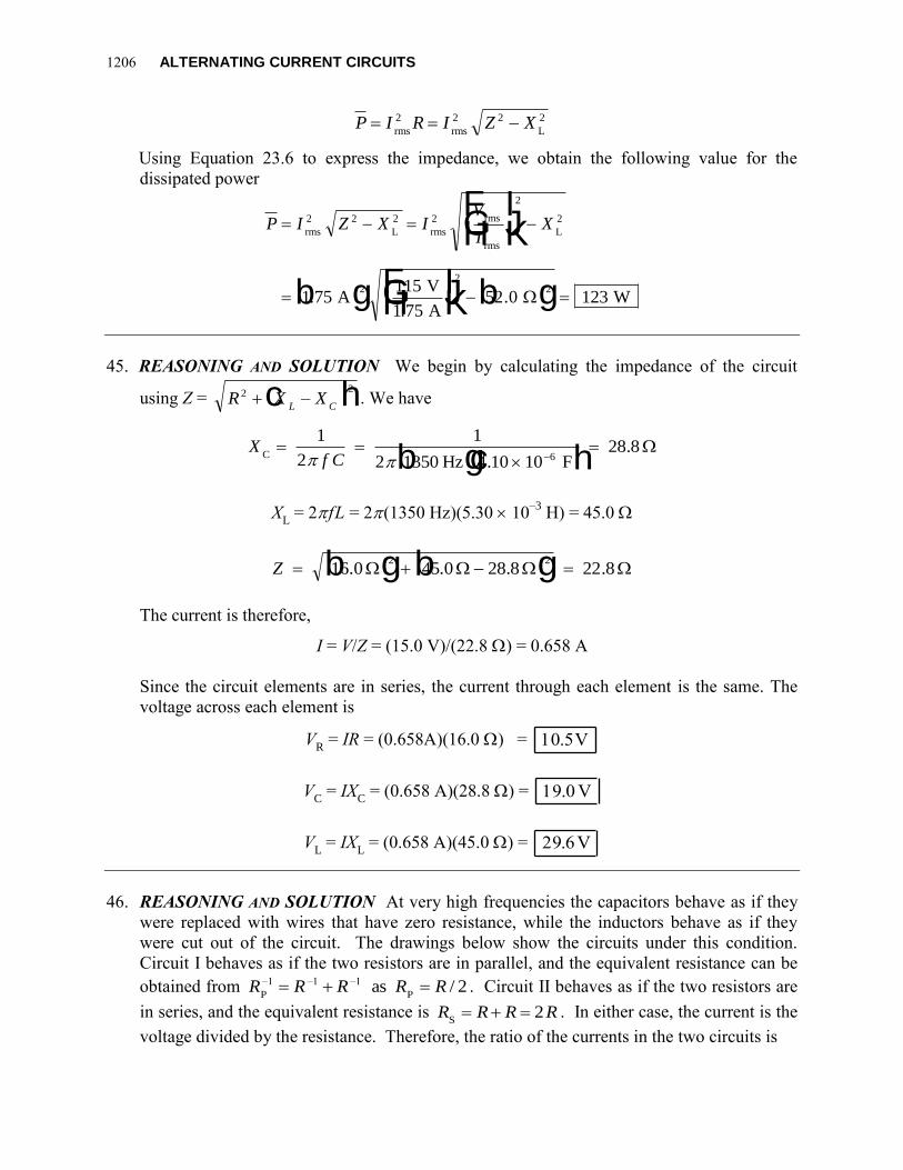
45. REASONING AND SOLUTION We begin by calculating the impedance of the circuit
using Z = R X XL C
2 2 –c h. We have
Xf CC
Hz F
1
2
1
2 1350 4 10 1028 8
6 b gc h..
XL = 2fL = 2(1350 Hz)(5.30 10
–3 H) = 45.0
Z 16 0 45 0 28 8 22 82 2
. . . . b g b g
The current is therefore,
I = V/Z = (15.0 V)/(22.8 ) = 0.658 A
Since the circuit elements are in series, the current through each element is the same. The
voltage across each element is
VR = IR = (0.658A)(16.0 ) = 10.5V
VC = IX
C = (0.658 A)(28.8 ) = 19.0 V
VL = IX
L = (0.658 A)(45.0 ) = 29.6V
46. REASONING AND SOLUTION At very high frequencies the capacitors behave as if they
were replaced with wires that have zero resistance, while the inductors behave as if they
were cut out of the circuit. The drawings below show the circuits under this condition.
Circuit I behaves as if the two resistors are in parallel, and the equivalent resistance can be
obtained from R R R R RP P
as–1 –1 –1 / 2 . Circuit II behaves as if the two resistors are
in series, and the equivalent resistance is R R R RS 2 . In either case, the current is the
voltage divided by the resistance. Therefore, the ratio of the currents in the two circuits is
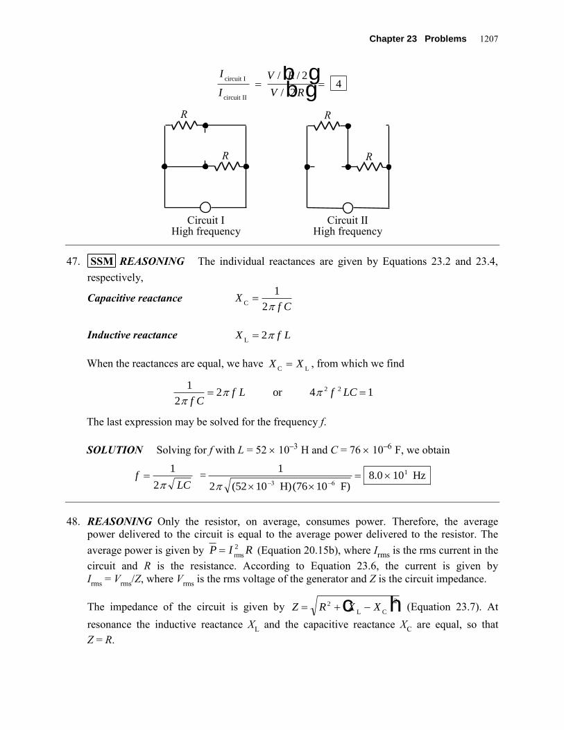
Chapter 23 Problems 1207
I
I
V R
V R
circuit I
circuit II
4 / /
/
2
2
b gb g
47. SSM REASONING The individual reactances are given by Equations 23.2 and 23.4,
respectively,
Capacitive reactance Xf CC
1
2
Inductive reactance X f LL 2
When the reactances are equal, we have X XC L , from which we find
1
22 12
f Cf L f LC or 4 2
The last expression may be solved for the frequency f.
SOLUTION Solving for f with L = 52 10 H and C = 76 10 F, we obtain
fLC
1
2
1
2 10 =
(52 (76 10 F)8.0 10 Hz
–6
1
–3 H)
48. REASONING Only the resistor, on average, consumes power. Therefore, the average
power delivered to the circuit is equal to the average power delivered to the resistor. The
average power is given by P I Rrms
2 (Equation 20.15b), where Irms is the rms current in the
circuit and R is the resistance. According to Equation 23.6, the current is given by
Irms
= Vrms
/Z, where Vrms
is the rms voltage of the generator and Z is the circuit impedance.
The impedance of the circuit is given by Z R X X 2 2
L Cc h (Equation 23.7). At
resonance the inductive reactance XL and the capacitive reactance X
C are equal, so that
Z = R.
R
R R
R
Circuit I High frequency
Circuit II High frequency
1208 ALTERNATING CURRENT CIRCUITS
SOLUTION Substituting Irms
= Vrms
/Z into P I Rrms
2 , the average power delivered to the
cricuit can be written as 2
2 rmsrms
VP I R R
Z
(1)
Substituting Z = R into Equation (1) yields
2 2 22
rms rms rms 3.0 V0.098 W
92
V V VP R R
Z R R
49. REASONING The rms current in an inductor is Irms
= Vrms
/XL, according to Equation 23.3.
The inductive reactance is XL = 2 f L, according to Equation 23.4. Applying these
expressions to both generators will allow us to obtain the desired current.
SOLUTION Using Equations 23.3 and 23.4, we find that the current in an inductor is
IV
X
V
f Lrms
rms
L
rms 2
Applying this result to the two generators gives
IV
f LI
V
f L1
rms
Generator 1
2
rms
Generator 2
and 2 2
1 2
Dividing the equation for generator 2 by the equation for generator 1, we obtain
I
I
V
f L
V
f L
f
fI I
f
f
2
1
2
1
1
2
2 1
1
2
2
2
0 30
rms
rms
or A1.5 kHz
6.0 kHz0.075 A
.b g
50. REASONING To find the frequency at which the current is one-half its value at zero
frequency, we first determine the value of the current when f = 0 Hz. We note that at zero
frequency the reactive inductance is zero (XL = 0 ), since XL = 2 f L (Equation 23.4). The
current at zero frequency is 0rms
I = Vrms/R (Equation 20.14), since the inductor does not play
a role in determining the current at this frequency. When the frequency is not zero, the
current is given by rms
I = Vrms/Z (Equation 23.6), where Z is the impedance of the circuit.
Chapter 23 Problems 1209
These last two relations will allow us to find the frequency at which the current is one-half
its value at zero frequency.
SOLUTION We are given that 01rms rms2
I I , so
rms rms1 or Z = 2
Z 2
V VR
R
Since the impedance of the circuit is 2 2L
Z R X (Equation 23.7) and XL = 2 f L
(Equation 23.4), the relation Z = 2R becomes
22 2 2R f L R
Solving for the frequency gives
3
3
3 16 31.1 10 Hz
2 2 4.0 10 H
Rf
L
51. SSM REASONING Since we know the values of the resonant frequency of the circuit,
the capacitance, and the generator voltage, we can find the value of the inductance from
Equation 23.10, the expression for the resonant frequency. The resistance can be found from
energy considerations at resonance; the power factor is given by cos , where the phase
angle is given by Equation 23.8, tan ( – ) / X X RL C
.
SOLUTION a. Solving Equation 23.10 for the inductance L, we find that
Lf C
1
4
1
4 10 1010
2
0
2 2 (1.30 (2.94
3 2 –6
–3
Hz) 5.10 F) H
b. At resonance, f f0, and the current is a maximum. This occurs when X X
L C , so
that Z R . Thus, the average power P provided by the generator is P V Rrms
2 / , and
solving for R we find
RV
P rms
2 2(11.0 V)
25.0 W4.84
c. When the generator frequency is 2.31 kHz, the individual reactances are
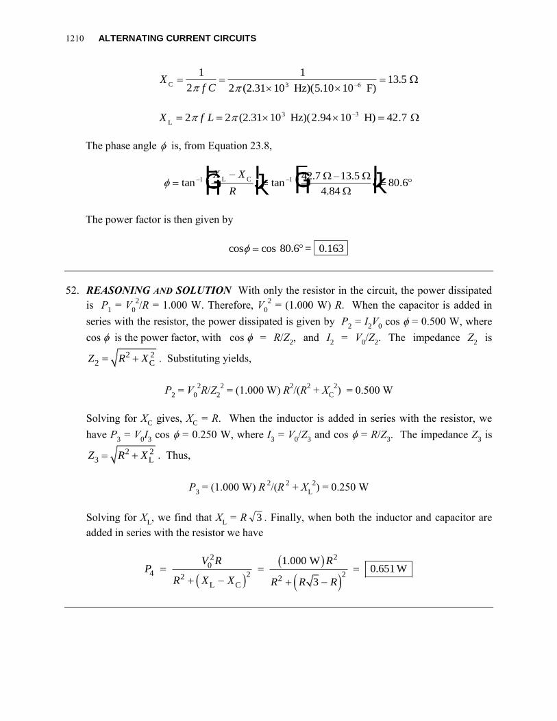
1210 ALTERNATING CURRENT CIRCUITS
Xf CC
(2.31 5
1
2
1
2 10 1013 5
3 –6 Hz)( .10 F).
X f LL
(2.31 2 2 10 2 10 42 7 3 –3 Hz)( .94 H) .
The phase angle is, from Equation 23.8,
FHG
IKJ
FHG
IKJ tan
–tan .–1 –1
X X
R
L C 42.7 –13.5
4.84
80 6
The power factor is then given by
cos cos 80.6 = 0.163
52. REASONING AND SOLUTION With only the resistor in the circuit, the power dissipated
is P1 = V
0
2/R = 1.000 W. Therefore, V
0
2 = (1.000 W) R. When the capacitor is added in
series with the resistor, the power dissipated is given by P2 = I
2V
0 cos = 0.500 W, where
cos is the power factor, with cos = R/Z2, and I
2 = V
0/Z
2. The impedance Z
2 is
2 22 C
Z R X . Substituting yields,
P2 = V
0
2R/Z
2
2 = (1.000 W) R
2/(R
2 + X
C
2) = 0.500 W
Solving for XC gives, X
C = R. When the inductor is added in series with the resistor, we
have P3 = V
0I3 cos = 0.250 W, where I
3 = V
0/Z
3 and cos = R/Z
3. The impedance Z
3 is
2 23 L
Z R X . Thus,
P3 = (1.000 W) R
2/(R
2 + X
L
2) = 0.250 W
Solving for XL, we find that X
L = R 3 . Finally, when both the inductor and capacitor are
added in series with the resistor we have
2 20
4 2 22 2L C
1.000 W0.651 W
3
V R RP
R X X R R R