Embed Size (px)
Citation preview

ANSYS Design Modeler and Meshing Tutorial:A Simple Duct Mesh
R1.00
Arpan R. SinghScott J. Ormiston
Department of Mechanical EngineeringUniversity of Manitoba
Canada
2019-09-10
University of Manitoba R1.00 Page 1 of 8

ANSYS DesignModeller and Meshing Tutorial: A Simple Duct Mesh 2019-09-10
1 IntroductionThis tutorial covers the steps neccessary to create a simple rectangular duct mesh using ANSYS Work-bench. The geometry has lengths of Lx = 2.0 [m], Ly = 0.2 [m], and Lz = 0.3 [m]. The geometry of thedomain is created in ANSYS DesignModeler. A uniform orthogonal mesh is then created in the domainusing ANSYS Meshing. The completed mesh is saved as file that is used in another tutorial: ANSYSCFX Tutorial: Laminar Flow in a Rectangular Duct.
2 Geometry1. Launch ANSYS Workbench.
2. At the top of the Workbench window, click File → Save As...Select an appropriate location for this project and set the file name to duct.Click Save.
3. In the Toolbox pane on the left side of the window, expand Component Systems if it has not alreadybeen expanded, then double click Geometry.The Project Schematic pane will have a new object named Geometry. Rename the label at thebottom of the object to “duct”. The screen should look similar to Figure 1.
Figure 1: How the Workbench window should appear at the end of Step 3 of Geometry
4. Right-click cell A2 (Labelled Geometry ?) in the newly shown Geometry object.In the new context menu, click New DesignModeler Geometry... A new DesignModeler window willlaunch as shown in Figure 2.
University of Manitoba R1.00 Page 2 of 8
ANSYS DesignModeller and Meshing Tutorial: A Simple Duct Mesh 2019-09-10
Figure 2: A new DesignModeler window
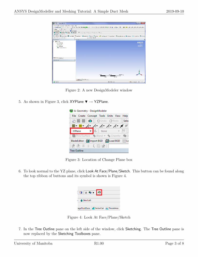
5. As shown in Figure 3, click XYPlane H → YZPlane.
Figure 3: Location of Change Plane box
6. To look normal to the YZ plane, click Look At Face/Plane/Sketch. This button can be found alongthe top ribbon of buttons and its symbol is shown is Figure 4.
Figure 4: Look At Face/Plane/Sketch
7. In the Tree Outline pane on the left side of the window, click Sketching. The Tree Outline pane isnow replaced by the Sketching Toolboxes pane.
University of Manitoba R1.00 Page 3 of 8
ANSYS DesignModeller and Meshing Tutorial: A Simple Duct Mesh 2019-09-10
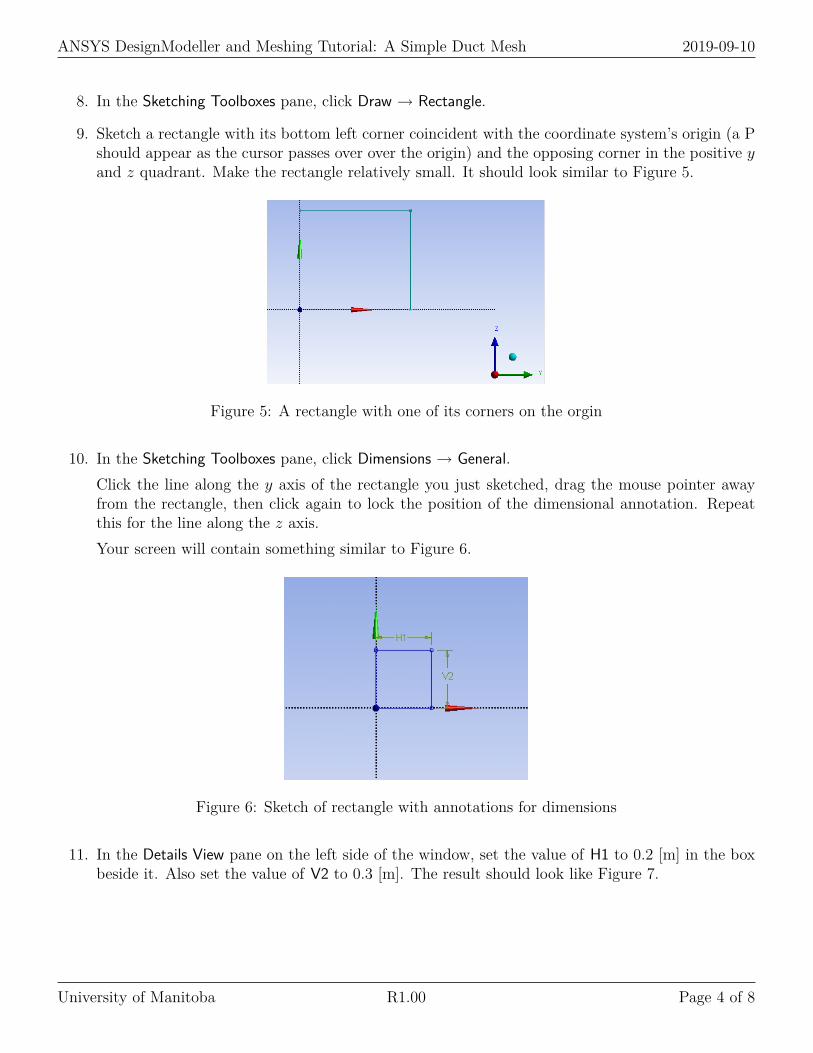
8. In the Sketching Toolboxes pane, click Draw → Rectangle.
9. Sketch a rectangle with its bottom left corner coincident with the coordinate system’s origin (a Pshould appear as the cursor passes over over the origin) and the opposing corner in the positive yand z quadrant. Make the rectangle relatively small. It should look similar to Figure 5.
Figure 5: A rectangle with one of its corners on the orgin
10. In the Sketching Toolboxes pane, click Dimensions → General.Click the line along the y axis of the rectangle you just sketched, drag the mouse pointer awayfrom the rectangle, then click again to lock the position of the dimensional annotation. Repeatthis for the line along the z axis.Your screen will contain something similar to Figure 6.
Figure 6: Sketch of rectangle with annotations for dimensions
11. In the Details View pane on the left side of the window, set the value of H1 to 0.2 [m] in the boxbeside it. Also set the value of V2 to 0.3 [m]. The result should look like Figure 7.
University of Manitoba R1.00 Page 4 of 8
ANSYS DesignModeller and Meshing Tutorial: A Simple Duct Mesh 2019-09-10
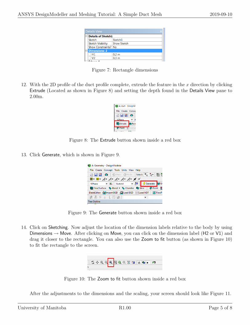
Figure 7: Rectangle dimensions
12. With the 2D profile of the duct profile complete, extrude the feature in the x direction by clickingExtrude (Located as shown in Figure 8) and setting the depth found in the Details View pane to2.00m.
Figure 8: The Extrude button shown inside a red box
13. Click Generate, which is shown in Figure 9.
Figure 9: The Generate button shown inside a red box
14. Click on Sketching. Now adjust the location of the dimension labels relative to the body by usingDimensions → Move. After clicking on Move, you can click on the dimension label (H2 or V1) anddrag it closer to the rectangle. You can also use the Zoom to fit button (as shown in Figure 10)to fit the rectangle to the screen.
Figure 10: The Zoom to fit button shown inside a red box
After the adjustments to the dimensions and the scaling, your screen should look like Figure 11.
University of Manitoba R1.00 Page 5 of 8

ANSYS DesignModeller and Meshing Tutorial: A Simple Duct Mesh 2019-09-10
Figure 11: The adjusted view of the rectangle and dimension labels
15. Click on ISO in the top ribbon of buttons (seen to the right of Zoom to fit in Figure 10). Thescreen should look like Figure 12.
Figure 12: Isometric view of the geometry
16. Now, assign names to all the faces of the domain. This steps involves selecting and generatinga face, followed by naming the face. To select the face, click on the Select Face button in thetop ribbon of buttons (the location is shown in Figure 13). If this button is greyed-out, click onModeling in the bottom of the Sketching Toolbox panel.
Figure 13: Face button
University of Manitoba R1.00 Page 6 of 8
ANSYS DesignModeller and Meshing Tutorial: A Simple Duct Mesh 2019-09-10
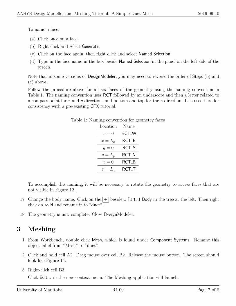
To name a face:
(a) Click once on a face.(b) Right click and select Generate.(c) Click on the face again, then right click and select Named Selection.(d) Type in the face name in the box beside Named Selection in the panel on the left side of the
screen.
Note that in some versions of DesignModeler, you may need to reverse the order of Steps (b) and(c) above.Follow the procedure above for all six faces of the geometry using the naming convention inTable 1. The naming convention uses RCT followed by an underscore and then a letter related toa compass point for x and y directions and bottom and top for the z direction. It is used here forconsistency with a pre-existing CFX tutorial.
Table 1: Naming convention for geometry facesLocation Namex = 0 RCT Wx = Lx RCT Ey = 0 RCT Sy = Ly RCT Nz = 0 RCT Bz = Lz RCT T
To accomplish this naming, it will be necessary to rotate the geometry to access faces that arenot visible in Figure 12.
17. Change the body name. Click on the + beside 1 Part, 1 Body in the tree at the left. Then rightclick on solid and rename it to “duct”.
18. The geometry is now complete. Close DesignModeler.
3 Meshing1. From Workbench, double click Mesh, which is found under Component Systems. Rename this
object label from “Mesh” to “duct”.
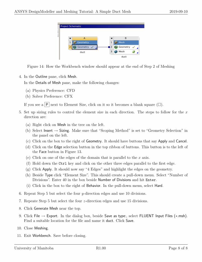
2. Click and hold cell A2. Drag mouse over cell B2. Release the mouse button. The screen shouldlook like Figure 14.
3. Right-click cell B3.Click Edit... in the new context menu. The Meshing application will launch.
University of Manitoba R1.00 Page 7 of 8
ANSYS DesignModeller and Meshing Tutorial: A Simple Duct Mesh 2019-09-10
Figure 14: How the Workbench window should appear at the end of Step 2 of Meshing
4. In the Outline pane, click Mesh.In the Details of Mesh pane, make the following changes:
(a) Physics Preference: CFD(b) Solver Preference: CFX
If you see a P next to Element Size, click on it so it becomes a blank square (�).
5. Set up sizing rules to control the element size in each direction. The steps to follow for the xdirection are:
(a) Right click on Mesh in the tree on the left.(b) Select Insert → Sizing. Make sure that “Scoping Method” is set to “Geometry Selection” in
the panel on the left.(c) Click on the box to the right of Geometry. It should have buttons that say Apply and Cancel.(d) Click on the Edge selection button in the top ribbon of buttons. This button is to the left of
the Face button in Figure 13.(e) Click on one of the edges of the domain that is parallel to the x axis.(f) Hold down the Ctrl key and click on the other three edges parallel to the first edge.(g) Click Apply. It should now say “4 Edges” and highlight the edges on the geometry.(h) Beside Type click “Element Size”. This should create a pull-down menu. Select “Number of
Divisions”. Enter 40 in the box beside Number of Divisions and hit Enter.(i) Click in the box to the right of Behavior. In the pull-down menu, select Hard.
6. Repeat Step 5 but select the four y-direction edges and use 10 divisions.
7. Repeate Step 5 but select the four z-direction edges and use 15 divisions.
8. Click Generate Mesh near the top.
9. Click File → Export. In the dialog box, beside Save as type:, select FLUENT Input Files (∗.msh).Find a suitable location for the file and name it duct. Click Save.
10. Close Meshing.
11. Exit Workbench. Save before closing.
University of Manitoba R1.00 Page 8 of 8