Embed Size (px)
Citation preview

ANTARIS small windturbines

2
The advantages of the ANTARIS Small Wind Turbines
- For exposed wind sites optionally with various rotor diameters (2.35 – 6.50 m)
- Low-noise blade profile
- For grid connected, heating systems and as battery charger
- Storm protection with helicopter function and electronic braking
- Easy to install
Data SheetsANTARIS small wind turbines 2.5 kW - 12.0 kW
General information on the ANTARIS Wind Power System
The ANTARIS wind turbine is a wind power system which is ideal for inland sites.
It was developed especially for grid feed-in, charging batteries (24 V DC / 48 V DC etc.) and for the support of heating systems.
As a result of the robust design the ANTARIS is also suitable for exposed wind sites, optionally with various rotor diameters (2.35 – 6.50 m). The manually la-minated rotor blades benefit from a computer-designed aerodynamic profile. Needless to say that each blade is dynamically and statically balanced and has an identification number and documentation.
To facilitate easy installation we set the focus on enabling fast setup and ma-nual installation of the turbine. Due to the robust design the ANTARIS is ext-remely efficient and for the base installation has a very attractive price. Here, special attention should be put on the excellent starting behaviour, which at a wind velocity below 2.8 m/sec. operates at a very low noise (43 – 49 dB). This means that the system can also be set up in housing areas.
Grid-connected operation requiers the Smart!wind and PowerOne inverter with characteristics matched to the ANTARIS and local wind conditions. The grid-connected inverters feature an according declaration of conformity and are registered for the grid-feed-in mode, the ENS are already integrated!
If the ANTARIS is used in heating applications a control cabinet with control electronics is used for the optimum wind characteristic management in con-junction to a heating rod with 6000 Watt!
-Example-
Example: ANTARIS 2.5 kW - 3.5 kW
Example: ANTARIS 5.5 kW - 10.0 kW

3
Alternator Turbine DataType 3-phasig
permanent magnetType Grid connected
heating systemEfficiency 92% Speed range 0 rpm – 600 rpmNominal capacity 3.0 kW Working range 130 rpm – 400 rpmMaximum capacity 4.5 kW Engagement speed 2.8 m/sNominal voltage 350 VAC Storm safety 13.0 m/sProtection class IP56 Max. wind velocity 58 m/s
Mechanical Data Storm ProtectionRepeller diameter 3.00 m (2.35 m) Automatic system Helicopter position, bra-
king resistance, electro-magnetic brake (optional)
Sweep area 7.065 m² (4.335 m²) Manually Short-circuit braking, braking resistance
Rotor blades 3 piece carbon / glass fibreRotor blade protection UV-, chemistry and
temperature resistantTurbine material High-temperature
galvanizedColour RAL 9010Total weight 95 kg
Standard norms and certificates:CE-DIN EN 60204-1
DIN VDE 0113 T 1DIN EN 12100
DIN EN 418Accident prevention regulation
BGV A3 (VBG4) accordinglyIEC 61400-2
ANTARIS 2.5 kW
Turbine characteristic ANTARIS 2.5 kW

4
Alternator Turbine DataType 3-phase
permanent magnetType Grid connected
heating systemEfficiency 92% Speed range 0 rpm – 600 rpmNominal capacity 3.7 kW Working range 115 rpm – 430 rpmMaximum capacity 7.5 kW Engagement speed 2.8 m/sNominal voltage 350 VAC Storm safety 13.0 m/sProtection class IP56 Max. wind velocity 58 m/s
Mechanical Data Storm ProtectionRepeller diameter 3.5 m (3.0 m) Automatic system Helicopter position, bra-
king resistance, electro-magnetic brake (optional)
Sweep area 9.61 m² (7.06 m²) Manually Short-circuit braking, bra-king resistance
Rotor blades 3 piece carbon / glass fibreRotor blade protection UV-, chemistry and
temperature resistantTurbine material High-temperature
galvanizedColour RAL 9010Total weight 105 kg
Standard norms and certificates:CE-DIN EN 60204-1
DIN VDE 0113 T 1DIN EN 12100
DIN EN 418Accident prevention regulation
BGV A3 (VBG4) accordinglyIEC 61400-2
ANTARIS 3.5 kW
Turbine characteristic ANTARIS 3.5 kW

5
Alternator Turbine DataType 3-phase
permanent magnetType Grid connected
heating systemEfficiency 92% Speed range 0 rpm – 350 rpmNominal capacity 5.5 kW Working range 75 rpm –300 rpmMaximum capacity 9.5 kW Engagement speed 2.8 m/sNominal voltage 350 VAC Storm safety 13.0 m/sProtection class IP56 Max. wind velocity 58 m/s
Mechanical Data Storm ProtectionRepeller diameter 4.0 m (3.5 m) Automatic system Helicopter position, bra-
king resistance, electro-magnetic brake (optional)
Sweep area 12.65 m² (9.61 m²) Manually Short-circuit braking, bra-king resistance
Rotor blades 3 piece carbon / glass fibreRotor blade protection UV-, chemistry and
temperature resistantTurbine material High-temperature
galvanizedColour RAL 9010Total weight 165 kg
Standard norms and certificates:CE-DIN EN 60204-1
DIN VDE 0113 T 1DIN EN 12100
DIN EN 418Accident prevention regulation
BGV A3 (VBG4) accordinglyIEC 61400-2
ANTARIS 5.5 kW
Turbine characteristic ANTARIS 5.5 kW
6
Alternator Turbine DataType 3-phase
permanent magnetType Grid connected
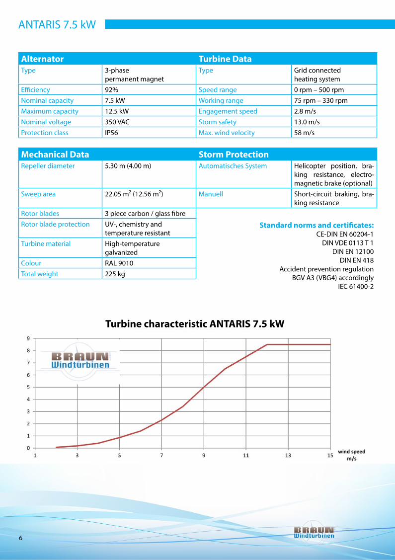
heating systemEfficiency 92% Speed range 0 rpm – 500 rpmNominal capacity 7.5 kW Working range 75 rpm – 330 rpmMaximum capacity 12.5 kW Engagement speed 2.8 m/sNominal voltage 350 VAC Storm safety 13.0 m/sProtection class IP56 Max. wind velocity 58 m/s
Mechanical Data Storm ProtectionRepeller diameter 5.30 m (4.00 m) Automatisches System Helicopter position, bra-
king resistance, electro-magnetic brake (optional)
Sweep area 22.05 m² (12.56 m²) Manuell Short-circuit braking, bra-king resistance
Rotor blades 3 piece carbon / glass fibreRotor blade protection UV-, chemistry and
temperature resistantTurbine material High-temperature
galvanizedColour RAL 9010Total weight 225 kg
Standard norms and certificates:CE-DIN EN 60204-1
DIN VDE 0113 T 1DIN EN 12100
DIN EN 418Accident prevention regulation
BGV A3 (VBG4) accordinglyIEC 61400-2
ANTARIS 7.5 kW
Turbine characteristic ANTARIS 7.5 kW

7
Alternator Turbine DataType 3-phase
permanent magnetType Grid connected
heating systemEfficiency 92% Speed range 0 rpm – 300 rpmNominal capacity 12.0 kW Working range 60 rpm – 250 rpmMaximum capacity 18.5 kW Engagement speed 2.2 m/sNominal voltage 350 VAC Storm safety 12.0 m/sProtection class IP56 Max. wind velocity 58 m/s
Mechanical Data Storm ProtectionRepeller diameter 6.50 m (5.30 m) Automatic system Helicopter position, bra-
king resistance, electro-magnetic brake (optional)
Sweep area 33.16 m² (22.05 m²) Manually Short-circuit braking, bra-king resistance
Rotor blades 3 piece carbon / glass fibreRotor blade protection UV-, chemistry and
temperature resistantTurbine material High-temperature
galvanizedColour RAL 9010Total weight 450 kg
Standard norms and certificates:CE-DIN EN 60204-1
DIN VDE 0113 T 1DIN EN 12100
DIN EN 418Accident prevention regulation
BGV A3 (VBG4) accordinglyIEC 61400-2
ANTARIS 12 kW
Turbine characteristic ANTARIS 12 kW

The small-wind turbine ANTARIS 7.5 kW is a small-wind turbine with horizontal rotor axis for generation of electric energy (see picture 1). The rotor, from wind direction, here is located before the mast (upwind arrangement). Three glass-fibre/carbon-fibre rotor blades directly drive a permanent magnet activated three-phase alternator. The generated electricity is directed to the tower base via vertically arranged ring wheels and a flexible cable. A wind vane orients the turbine according to the wind conditions. The ANTARIS features a flange at the swivel due to which it is possible to set up the turbi-ne on various mast systems. At a certain wind velocity the rotor tilts upwards into the helicopter position and with this limits the power by decreasing the circular area.
Building specificationon the example of an ANTARIS 7.5 kW Small Wind Turbine
Picture 1: ANTARIS 7.5 kW
Listing of single components
Tilting element with Azimuth swivel
- Power transmission through ring wheels, through this no twisting of cable is possible- Bearing parts are made from high temperature galvanized steel- Bolted connections made from stainless steel- Wind vane made from weatherproof HDPE (see picture 2 and 3)- Storm safety through tilting upwards of the rotor into the helicopter position (see picture 3.1)
Picture 2: Gondola housing
Picture 3: Spinner
Picture 3.1: Tilting element with alternator
8

9
Alternator CK 11.0, 160 M (see picture 4)
- Permanent magnet with rotor, brushless, gearless, maintenance-free- High efficiency through strong permanent magnets (NdFeBo magnets, 150° temperature resistant) - 3-phase current- Separator rectifier- Direction of rotation in any way- Voltage 0 – 100 Volt- Loading start at approx 75 rpm- Power min. 8500 Watt (100% overload resistant)- Rampant output curve by increase number of revolutions- Weight: approx. 87 kg- Aluminium case, foot mounting- Protection mode IP56
Picture 4: CK11 Alternator
Electronic control of the WKA 1-phase(see picture 5)
- Control electronics with voltage monitoring- Connections / plugs protected against polarity reversal - 3-phase alternator monitoring- Emergency stop switch- Reset switch- Rectifier, voltage display, …- 1 piece 7.0 braking resistance (dump load)
Redundant braking systems of the turbine:- Helicopter position- Electronic voltage monitoring- Short-circuit switch (eddy current brake) for shut-off of the turbine during maintenance
Picture 5: Upper left: control cabinet, right-side: Windy Boy from the company SMA, bottom: braking resistance
Rotor (see picture 6)
- Hub connection with aluminium flange and VA-pressure disc- Stainless steel bolt connections- 3 Rotor blades made from glass-fibre/ carbon-fibre laminate - Aerodynamic profile- Noise minimizing through winglets on the rotor tips as well as additional turbulators- Ø 5,30 m efficient circular area- Weight of single blade: approx. 9.3 kg- Dynamically and statically balanced- Rotation direction front ‘left’- Speed max. 300 rpm- GFK spinner cap- Rotor colour ‘white’
Picture 6: Aluminium shaft with VA pressure disc

Inverter / Grid feed-in
Picture 7
10
Pipe-, lattice- or tilt masts
- According to the customer needs pipe or lattice masts with stability declarations are available (see pictures 9 and 10)- Up to 12 m there is also the possibility to use the pipe masts as tilt masts- Hydraulics on request
Smart Power Electronics - Smart!wind (see picture 7.1)
- Inverter with integrated grid monitoring- Through the optimized turbine characteristic the wind turbine load is optimized according to the wind velocity (see picture 8).- Including display and optional interface for reading data
ABB - PowerOne (see picture 8)for ANTARIS 2.5 - 3.5 kW
The PVI-3.0/3.6/4.2-TL-W wind inverter is equipped with the proven high-quality technology of ABB. The PVI wind inverter does not have a transformer and features a unique combination of high efficiency, in-stallation friendly design and a very wide range for the initial voltage through which a high energy harvest is gained. The high control speed and the precise tracking algorithm for the power characteristic allow to adapt the characteristic to the according turbine locations in an opti-mum way.
Picture 8
Smar
t!w
ind
Power O
ne

11
Lattice mastsfor ANTARIS wind power plants from 2.5 kW to 12.0 kW
Picture 9: Lattice masts (from 12 m to 24 m)
Pipe mastsfor ANTARIS wind power plants from 2.5 kW to 12.0 kW
Picture 10: Pipe masts from the company SAW
7 m 9,20 m 12 m 15 m 18 m 21 m 24 m
12 m lattice mast 15 m lattice mast 18 m lattice mast 21 m lattice mast 24 m lattice mast1 x 3 m + 1 x 6 m 2 x 6 m lattice 1 x 3 m + 2 x 6 m 3 x 6 m lattice 3 x 6 m + 3 mlattice + 3 m pipe + 3 m pipe lattice + 3 m pipe + 3 m pipe lattice + 3 m pipe

12
Installation and operation manualFor small-wind turbines (KWEA)
These manual should be used together with the manual of the grid-feed-in inverter, the commissioning and main-tenance obligations book, the documentation for the mast, possibly constraints due to building permissions and further technical documents related to this turbine.
Subject to technical modifications related to technical progress. The most current version is available under: www.braun-windturbinen.com
Some activities can only be performed by an electrician. For all further steps on the turbine we recommend the trainings offered by us or our partners. Simply contact us!
Small-wind turbines for feed-in to the individual home grid for optimizing home requirements, grid feed-in into to the public grid and feed-in into island grid. The turbine is suitable for wind zone III according to DIN EN 61400-2 for an annual mean of wind velocity on shaft level (vave) of 7.5 m/s. Usage for other applications as well as offshore, in extreme altitudes, at danger through ice, earthquake and storm areas, in regions with tropical hurricanes, is not allowed. Extended versions of the KWEA can be issued by the manufacturer on demand. The turbine is delivered together with an optimized grid-feed-in inverter and suitable braking resistances; modifications to the system have to be discussed and released by the manufacturer. Modifications to the system without written agreement from the manufacturer lead to the loss of warranty claims and to termination of the conformity agreement.
ANTARIS small-wind turbines are industrially manufactured using the utmost modern technologies and corrosion resistant materials and fulfill the according EU standards. They are almost maintenance free and function reliably for many years.
Field of application

13
Safety instructionsWarning! Take care of the safety instructions
On planning the location, the installation and operation of the wind small turbine, security has to be put in first place. For the single use case consider all valid security and accident prevention regulations! The small wind turbine should only be set up at locations were risks to humans and the environment can be excluded!For your own safety use suitable tools to prevent falling from the mast during installation and maintenance.
- Install the turbine with utmost caution; take care that during installation nobody is close to the mast!- Install the wind turbine only during mild- or no-wind conditions and in ice free and dry weather. - When working on the turbine block the rotor blades by short-circuit of the alternator or tie the blades to the mast. Fast-running rotor blades can reach very high velocities at the blade tip and are of great danger when touched!- During electric installation note that the alternator already at low speed generates a high voltage and therefore only install when the rotor is blocked. - Install the rotor blades only after complete electric installation!- Use the sufficiently dimensioned cables to prevent heating and possibly cable fire. Sufficiently secure all feed lines. No fuse shall be installed between alternator and main switch, as well as between main switch and grid-feed-in inverter. - Consider the DIN VDE 0100 ‘Regulations for the installation of strong currency plants up to 1000 Volt- Consider that falling parts (e.g. ice when frosty, loose or damaged rotor blades) can be hurled long distances at fast rotation. - At strong vibrations reduce the alternator speed and prior to restart remove imbalances (e.g. ice), long-term vibrations can lead to early material fatigue and can lead to complete damage through break-down of the turbine. - Reduce the speed in case of storm forecasts during extreme wind velocities.
Scope of supply – Components of the small wind turbineWhen unpacking please check the completeness and integrity of all single components.Apart from this manual the following components are included:
- 1 alternator feed line (only by using slip rings)- 1 piece grid feed-in inverter Smart!wind SW7.5 or SW-10- 1 piece braking resistance with 6 kW and 18 Ohm for the Antaris 7.5 kW- 2 pieces braking resistance with 6 kW and 25 Ohm for the Antaris 12.0 kW- 1 piece of this manual- 1 piece installation and maintenance obligation book
- 1 piece steel console with alternator and Azimuth bearing, pre-assembled- 1 piece wind vane- 1 piece square pipe as wind vane cantilever- 1 piece gondola housing- 1 piece spinner cap- 1 piece rotor hub- 1 piece pressure disc for rotor blades- 15 screws M8x100 with self-securing nuts and shims- 6 screws M4x15 for spinner fixation- 3 rotor blades

14
OperationThe rotor blades are mounted to the alternator and through their rotation convert the kinetic energy of the wind into rotation energy. The alternator converts this into electric energy which is transferred to the connection point with the main switch via the alternator feed. During operation the alternator feed is twis-ted through the directional tracking and has to be untwisted regularly as far as there are no slip rings in the Azimuth bearing.The alternator provides a variable voltage and frequency depending on the respective rotor speed. This is at first commutated by the grid feed-in inverter and then increased in order to be feed into the home-/public-/island net. The wind vane independently aligns the turbine to the wind.
Safety installations At storm the turbine independently tilts upwards into the helicopter position and with this decreases the target for the wind and limits the energy intake through the wind. This braking system is also effective when no load is connected to the alternator. On reaching the warning speed the turbine speed is reduced through additional usage of braking resistance via the inverter. On reaching the error speed the turbine speed is reduced until stop of the turbine. The reset happens automatically after 2 hours. With the key switch on the mains inverter the turbine speed is reduced through the braking resistances. After speed reduction the alternator can be short-circuited via the main switch directly on the mast.
With short-circuit the braking force on the alternator is that large that the rotor even during strong storms cannot rev up. The main switch with the alternator short circuit shall only be used at low rotor speed, at first reduce speed via the key switch. Should speed reduction via the key switch on the mains inverter should not be possible, use the main switch during period of shortly lower wind velo city if possible. If during a strong storm after a maximum of 2 minutes it is not possible to reduce the rotor to a lower speed via the main switch turn the switch off to avoid a burn-through of the alternator. After 30 minutes cool-down time again reduce speed.
Circuit diagram for island operation
• Independent energy supply• Freely selectable energy sources• Free adaption to local conditions

15
Circuit diagram for parallel operation to the grid
Circuit diagram for heating operationANTARIS
wind turbine
Heating cartridge
Buffer storage
Solar-ther-mal system
Photovoltaic
Direct current
Alternating current
Public net
Direct currentAlternating current
Alternating current
Mains inverterControl unit

16
Choice of location for setupThe energy to be taken from the wind increases by the cube of the wind velocity. This means that doubling the wind velocity will eightfold the energy harvest. For threefold, the power of the wind increases to the 27-fold! Therefore it is important to find the optimum location with good wind conditions for the wind power plant.
InstallationPlease read the entire installation instructions prior to planning the setup date and then individually plan the steps according to the local possibilities and conditions.The installation can easily be performed with a car mounted crane or from a lifting platform. If this is not possible, you can place the turbine on the mast with a wrecking crane with a guide pulley or hoist mounted to the mast top. If there is no possibility to use a crane or lifting platform you can also use a foldable mast. Alternatively a pipe mast which can be mounted lying on the ground and set up using a tilting mast. For some screws self-securing nuts with a plastic insert are used. These nuts can only be used once! If used more than once they lose their self-securing properties and therefore display a se-curity risk: Therefore, only use new nuts with undamaged plastic insert and without visible imprint of the thread. For the stainless screws only use stainless shims and stainless nuts as well as suitable tools.
Work on the electric installation shall only be performed by an electrician. Mounting the plant is easy, however should only be done by people with according experience. For the installation, in prin-ciple, you only require standard tools and a torque wrench. The underground cable from the main switch at the bottom of the mast is not within the scope of supply. You can take the required spanner openings and tightening moments for the screws of the mast from its documentation. In most ca-ses, freestanding masts are used. After the mast has been screwed to the fundament the machine support, the generator and the rotor are mounted on to the mast in this order. If a lifting platform is available for reasons of maximum load the machine support and generator should be mounted sepa-rately. With a crane the weight is not of concern and generator and machine support should be bol-ted together on the ground. Alternatively, the entire plant can be mounted to the mast when it is not yet standing (without repeller blades and gondola case) and can be pulled up or folded up together with the mast. Please select an according order for the local conditions. The following pictures from several projects give you some hints for the various possibilities. The commissioning and maintenan-ce obligations booklet contains a checklist which needs to be followed through prior to the first start.
Turbulence range

17
The energy to be taken from the wind increases by the cube of the wind velocity. This means that doubling the wind velocity will eightfold the energy harvest. For threefold, the power of the wind increases to the 27-fold! Therefore it is important to find the optimum location with good wind conditions for the wind power plant.
Picture 1: Freestanding mast readily mounted Picture 2: Installation of the lower flange (anchorage) into the fundament with the inner empty conduit for the generator connecting cable
The mast is grounded via a grounding strap. Also connect the fundament reinforcement with the screws in the fundament or via a separate groun-ding with the mast. In case of insecure grounding conditions the grounding resistance should be checked through a measurement and has to be reche-cked regularly. Prior to mounting the mast and to starting the plant the fun-dament has to harden fully. For this, depending on the additions in the concrete and the weather conditions several weeks can be necessary. For this also see installation instructions of the mast.
Picture 3: Ready fundament with the screws for the mast and the empty conduit for the generator connection
1. Fundament

18
The underground cable to the inverter should be pulled through the empty conduit prior to the mast and should reach approx. 3 m out of the fundament. Prior to mounting the mast to the fundament, the free end is pulled through the mast and the mounting opening from the bottom and secured against feedback. The freestanding mast is bolted to the fundament and balanced perpendicularly according to separate installation instructions.
2. The Mast
The generator connecting cable is pulled through the mast from the top prior to mounting the wind energy system. The flange of the plant is placed on the mast flange and installed with 8 high-strength screws M16, security shims and nuts. Use the supplied galvanized screws from the strength class 10.9 and the according pressure re-sistant shims and nuts, also from strength class 10. Self-securing nuts with plastic insert or spring rings are not suitable. The nuts are greased with molybdenum disulphide or similar are tightened equally with 250 Nm. After this you cover the generator with the case (large opening at the front) and bolt it to the ground plate of the tilting device. The generator with the azimuth swivel has to move freely into all directions. Balance the generator exactly perpendicularly.
3. Mounting the azimuth swivel with alternator and case
Picture 4: Machine gondola bolted to the mast while on the ground
The wind vane is bolted to the fixed part via a rectan-gular pipe. The wind vane is bolted to the screw with 4 screws M8x70 with shims and self-securing nuts.
4. Mounting the wind vane
Picture 5: Pipe to the wind vane screwed to machine sup-port. The 4 screws M12 are tightened with 50 Nm.

19
Mount the rotor blades to the alumi-nium hub. Take care that the hollow side of the blades is placed towards the front (into wind direction). Now bolt the blades lightly with the sup-plied screws. Adjust the blades so that the blade tips all have the same distances to each other. Now tighten the screws.
5. Mounting of the rotor blades and the spinner
Picture 6: Mounting of the rotor blades with 15 screws M8, shims and self-securing nuts between the hub on the generator shaft and pressure disc. The rotation direction on looking at the rotor is to the right. The reinforced rounded edge (leading edge) of the rotor blade cuts the wind. Evenly tighten the nuts according to the maintenance booklet with 15 Nm with a tightening wrench.
Picture 7: Pre-mounted rotor
The wind vane is mounted to the freestanding part of the machine support via a rectangular pipe. The wind vane is bolted to the pipe with 4 screws M8x7ß with shims and self-securing nuts.
Picture 8: Separate mounting of the machine support and ro-tor onto a freestanding mast with crane and lifting platform. On sufficient ultimate load of the lifting platform the parts can also be transported to the top of the mast separately.

The generator is connected to the mains inverter via a 3-core cable NYY-O 3x4.0 mm at up to 30 m cable length or NYY-O 3x6.0 at up to 80m cable length from the main switch (construction side). No safety switch or other separation switch shall be built into this connection. The generator case is connected to the mast and grounded together with the mast. A connection between the grounding of the mast with the grounding of the mains inverter is not recommended. The securing of the net connection is perfor-med according to the operation instructions of the mains inverter and the local conditions.
6. Electric connection
The mains inverter is supplied readily calibrated. First, execute the checks from the commissioning and maintenance booklet and check the electrical connection. First switch the main switch to OFF (AUS) (generator short circuit) and release if necessary the fixed rotor blade. The key switch on the mains inverter needs to be on Off. The first start of the rotor should take place in low wind conditions. Switch the main switch of the plant to Ein, after that switch the key switch to Ein and ob-serve the operation of the rotor. Now immediately test the braking with the key switch. If the key switch is set to OFF (AUS) the plant speed is reduced. If this is not the case immediately set the main switch on the mast to OFF (AUS).
7. Initial start-up
20
Picture 9: Overview electric circuit diagram
Ground generator together with the mast
1x 18 Ohm for the Antaris 6.5 kW2x 25 Ohm for the Antaris 12.0 kW
Braking resistance 6kW 25 Ohm
Braking resistance 6kW 18 Ohm or 25 OhmSmart!wind
SW-7.5 or SW-10
Key switch
3x4m
m2
sola
r cab
le
5x 2.5mm2 at short cable length
Net connection according to local conditions
Max. of 3 m cable length each

21
Technical DataWind grade according to EN IEC 61400-2:2006 IIIAnnual mean of the wind velocity on hub level (vave) 7,5 m/sReference velocity mean over 10 minutes (vref ) 37,5 m/sTurbulence intensity (I15) 0,18
Start speed 2,1 m/sStorm safety above 12… 13 m/s
Wind velocity above 20 m/s according to this happen for more than 33 hours within a year, above 25 m/s only for 1.4 hours per year.
Picture 10: Calculated frequency distribution of the wind velocity for grade III according to the Rayleigh distribution
Components: Manually laminated profile from glass and carbon fibre, dynamically and statically balan-ced, hub connection with aluminium flange and pressure disc. GFK spinner cap.
Number of rotor blades 3Rotation direction rightRotor area at 5.3 m diameter 22.1 m2 Weight per rotor blade 9.3 kg Weight per rotor hub 5kgRotor area at 6.5 m diameter 33.2 kg Weight per rotor blade 14 kg Weight per rotor hub 15 kg
Rotor
Rated power (Antaris 7.5 kW) 7.500 WRated power (Antaris 12.0 kW) 12.000 WMaximum power (Antaris 7.5 kW) 12.500 WMaximum power (Antaris 12.0 kW) 18.000 WRated speed (Antaris 7.5 kW) 330 min-1
Rated speed (Antaris 12.0 kW) 250 min-1
Weight (Antaris 7.5 kW) 87 kgWeight (Antaris 12.0 kW) 150 kgRated voltage 350 VAC
Alternator
Machine support with wind vane and without generator and rotor
Weight (Antaris 7.5 kW) 108 kgWeight (Antaris 12.0 kW) 235 kg
Total system on the mast
Weight (Antaris 7.5 kW) 225 kgWeight (Antaris 12.0 kW) 450 kg
rate
/ fr
eque
ncy
speed

22
Power characteristicsA
NTA
RIS
7.5
kWA
NTA
RIS
12.0
kW
Via Smart Power Electronics Smart!wind SW-7.5 and SW-10
Grid connection 400 Vconductor-conductorPhase number 3Output power, maximum (Antaris 7.5 kW) 7.500 WOutput power, maximum (Antaris 10.0 kW) 10.000 WOutput current, nominal value (Antaris 6.5 kW) 0…11 AOutput current, nominal value (Antaris 9.5 kW) 0…16 AOutput frequency, nominal value 50 HzOutput frequency, allowed range 47,5 … 51,5 HzSeparation concept without transformer, no galvanic separationGrid- / system security – ENS VDE AR-N 4105
Grid feed-in
Temperature: -30 … +55 °CSuitable for ice disposition: on request
Further environment conditions
Turbine characteristic ANTARIS 7.5 kW
Turbine characteristic ANTARIS 12.0 kW

23
Maintenance
In order to ensure safe operation for several years it is necessary to check the wind turbine in re-gular maintenance intervals. The maintenance work is described in the commissioning and main-tenance obligations booklet. The work needs to be documented. Preprints are available in the appendix of the maintenance obligations booklet or under www.braun-windturbinen.com.
Warranty
ANTARIS wind turbines are continuously developed and improved on behalf of technical pro-gress. Should your device however show a defect within the warranty time please refer to the spe-cialist dealer from which you purchased the plant. The claim for warranty is not valid, if the commis-sioning and regular maintenance have not been performed and documented according to the commissioning and maintenance obligations booklet. The mandatory transfer of the commissioning protocol happens via E-Mail to [email protected], via fax +49 (0)2747 / 914053 or per post.
The warranty period for ANTARIS wind turbines with inverter is 24 months, starting from the day of com-mission or 30 months starting from the day of delivery.
Warranty period
Your ANTARIS wind turbine has warranty related to material errors. This warranty does not include the accessories kit or other further parts of the plant from repairs. The warranty is invalid in case of improper use and improper installation.
Limited warranty
The warranty is only valid if the commissioning protocol has been filled out correctly and sent to us. The warranty includes the exchange of defect parts in the factory in case of damages that are not related to improper use. The parts need to be sent to the factory for repairmen or replacement. The buyer is respon-sible for shipping costs.
The warranty does not include costs for transport. Wind power plants that are excluded from warranty are also repaired and sent back. For this repairmen costs will be charged.
Warranty conditions

Inha
lt, B
ilder
& T
exte
: BR
AUN
Win
dtu
rbin
en G
mb
H |
Des
ign,
La
yout
& P
rint:
mob
ucon
.de