Embed Size (px)
Citation preview

Antenna Pointing Guide
1039429-0001
Revision B
September 10, 2013
11717 Exploration Lane, Germantown, MD 20876
Phone (301) 428-5500 Fax (301) 428-1868/2830

Copyright © 2013 Hughes Network Systems, LLC
All rights reserved. This publication and its contents are proprietary to Hughes Network Systems, LLC. No part of this publication may be reproduced in any form or by any means without the written permission of Hughes Network Systems, LLC, 11717 Exploration Lane, Germantown, Maryland 20876.
Hughes Network Systems, LLC has made every effort to ensure the correctness and completeness of the material in this document. Hughes Network Systems, LLC shall not be liable for errors contained herein. The information in this document is subject to change without notice. Hughes Network Systems, LLC makes no warranty of any kind with regard to this material, including, but not limited to, the implied warranties of merchantability and fitness for a particular purpose.
Trademarks
HUGHES and Hughes Network Systems are trademarks of Hughes Network Systems, LLC. All other trademarks are the property of their respective owners.

Contents
1039429-0001 Revision B 3
Contents Contents ................................................................................................. 3
Understanding safety alert messages .................................................... 5 Messages concerning personal injury .................................................................... 5 Messages concerning property damage ................................................................ 5 Safety symbols ....................................................................................................... 6
Additional symbols ........................................................................................... 6
Chapter 1 Introduction ........................................................................................... 7 Scope and audience ............................................................................................... 7 Related instructions ............................................................................................... 7 Antenna pointing overview ................................................................................... 7
Pointing tools and user interfaces .................................................................... 7 Pointing tools .................................................................................................... 8 Entering installation parameters ...................................................................... 9
Chapter 2 Pointing antenna using the DAPT2 ....................................................... 11 Prerequisites ........................................................................................................ 11
Entering installation parameters .................................................................... 11 Pointing ................................................................................................................ 14 Registration .......................................................................................................... 17 Troubleshooting ................................................................................................... 19
Chapter 3 Pointing the antenna using wireless device ......................................... 21 Prerequisites ........................................................................................................ 21
Setting up the Wi-Fi device ............................................................................. 21 Point and activate terminal with wireless device ........................................... 22
Acronyms .............................................................................................. 27 Index .................................................................................................... 27


Understanding safety alert messages
1039429-0001 Revision B 5
Understanding safety alert messages Safety alert messages call attention to potential safety hazards and tell you how to avoid them. These messages are identified by the signal words DANGER, WARNING, CAUTION, or NOTICE, as illustrated below. To avoid possible property damage, personal injury, or in some cases possible death, read and comply with all safety alert messages.
Messages concerning personal injury The signal words DANGER, WARNING, and CAUTION indicate hazards that could result in personal injury or in some cases death, as explained below. Each of these signal words indicates the severity of the potential hazard.
DANGER indicates a potentially hazardous situation which, if not avoided, will result in death or serious injury.
WARNING indicates a potentially hazardous situation which, if not avoided, could result in death or serious injury.
CAUTION indicates a potentially hazardous situation which, if not avoided, could result in minor or moderate injury.
Messages concerning property damage A NOTICE concerns property damage only.
NOTICE is used for advisory messages concerning possible property damage, product damage or malfunction, data loss, or other unwanted results—but not personal injury.

6 Understanding safety alert messages
1039429-0001 Revision B
Safety symbols The generic safety alert symbol
calls attention to a potential personal injury hazard. It appears next to the DANGER, WARNING, and CAUTION signal words as part of the signal word label. Other symbols may appear next to DANGER, WARNING, or CAUTION to indicate a specific type of hazard (for example, fire or electric shock). If other hazard symbols are used in this document they are identified in this section.
Additional symbols
This document uses the following hazard symbols:
Indicates a safety message that concerns a potential electric
shock hazard.
Indicates a safety message that concerns a potentially
hazardous situation in which you could fall.
Indicates a safety message that concerns a possible fire hazard.
Indicates a safety message that concerns radio frequency (RF)
energy.

Chapter 1 • Introduction
1039429-0001 Revision B 7
Chapter 1
Introduction
Scope and audience This document explains how to point JUPITER system antennas. This document is written for professional installers who have experience with installing and pointing satellite antennas.
Related instructions This pointing guide discusses the antenna pointing only. For antenna installation and mechanical adjustments on the antenna, see the specific installation guide for the antenna you are installing. A Ka-band radio assembly must be installed with the antenna before pointing.
Antenna pointing overview The antenna pointing procedure is a critical part of the JUPITER antenna installation process. If the satellite antenna is not properly pointed toward the satellite, it cannot communicate with the satellite to its full capacity, resulting in a degradation of system performance.
The basic requirement when pointing a JUPITER antenna is to accurately aim the antenna at the satellite to within 0.2 dB maximum loss of reception and 0.45 dB maximum loss of transmission. The JUPITER system uses a narrow Ka-band beam which can be sensitive to pointing errors; therefore, it is critical that the antenna is pointed properly and accurately.
To accurately point the antenna, follow the procedures in this manual exactly as they are written.
The antenna pointing process is divided into three tasks:
Entering installation parameters Pointing Registration
Under normal conditions and circumstances, a single professional installer can perform this process alone.
Pointing tools and user interfaces
Antenna pointing requires the use of several tools, as described in the following sections.

8 Chapter 1 • Introduction
1039429-0001 Revision B
Global Positioning System (GPS) receiver
Use a GPS receiver (not supplied) to determine the exact latitude and longitude coordinates of the antenna site. These coordinates are used to determine the correct azimuth and elevation information for the antenna to point at the satellite.
Your GPS receiver must be accurate to within 15 m. Most commercially available receivers meet this requirement. Units employing Wide-Area Augmentation System (WAAS) technology provide accuracy to 3 m.
The GPS must display latitude and longitude information in the format
DD MM.mmm
where DD = degrees, MM = minutes, and mmm = fractional minutes
The unit must display fractional minutes to three significant digits.
Local User Interface (LUI)
The LUI is the satellite modem interface. It is used to enter installation parameters required for pointing the antenna. The LUI also displays the beacon signal strength for monitoring purposes. To access the LUI, you must first connect your laptop to the indoor unit (satellite modem), then you will use a standard Internet browser (Internet Explorer version 8 or higher, Mozilla Firefox 3.6 or higher, and Google Chrome version 17 or higher) to navigate to the LUI. See Entering installation parameters on page 9 for the exact procedure.
Pointing tools
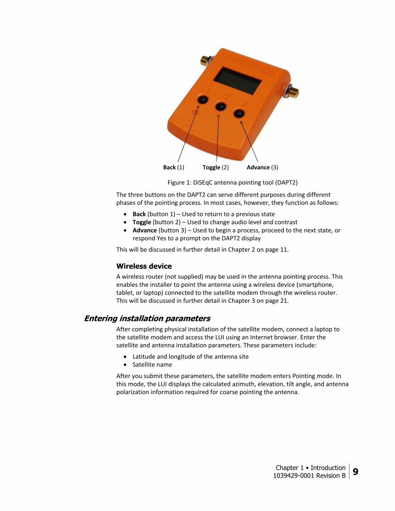
DiSEqC Antenna Pointing Tool (DAPT2)
The DAPT2 is a two-way digital satellite equipment control (DiSEqC) tool. It has a large backlit display and three buttons that enable the installer to step through the antenna pointing procedure. The DAPT2 is orange in color and it has a built-in audio feature to enhance the pointing process. Figure 1 shows the DAPT2.
Chapter 1 • Introduction
1039429-0001 Revision B 9
Figure 1: DiSEqC antenna pointing tool (DAPT2)
The three buttons on the DAPT2 can serve different purposes during different phases of the pointing process. In most cases, however, they function as follows:
Back (button 1) – Used to return to a previous state Toggle (button 2) – Used to change audio level and contrast Advance (button 3) – Used to begin a process, proceed to the next state, or
respond Yes to a prompt on the DAPT2 display
This will be discussed in further detail in Chapter 2 on page 11.
Wireless device
A wireless router (not supplied) may be used in the antenna pointing process. This enables the installer to point the antenna using a wireless device (smartphone, tablet, or laptop) connected to the satellite modem through the wireless router. This will be discussed in further detail in Chapter 3 on page 21.
Entering installation parameters
After completing physical installation of the satellite modem, connect a laptop to the satellite modem and access the LUI using an Internet browser. Enter the satellite and antenna installation parameters. These parameters include:
Latitude and longitude of the antenna site Satellite name
After you submit these parameters, the satellite modem enters Pointing mode. In this mode, the LUI displays the calculated azimuth, elevation, tilt angle, and antenna polarization information required for coarse pointing the antenna.
Back (1) Toggle (2) Advance (3)

10 Chapter 1 • Introduction
1039429-0001 Revision B
Azimuth measurements are calibrated relative to true north, not magnetic north.
Pointing
After entering the installation parameters, you can begin the process of pointing the antenna at the satellite. Using the proper azimuth, elevation, and tilt coordinates obtained from the LUI, you will point the antenna in the general direction of the satellite to obtain initial acquisition of the satellite signal.
Do not attempt to point the antenna manually by pulling on the antenna reflector or the feed support arm. This can cause permanent damage to the antenna reflector. Instead use the antenna mechanical adjustments.
When the demodulator locks onto the satellite beacon signal, the signal quality factor (SQF) of the received signal-to-noise ratio (SNR) pointing signal appears on the DAPT2 or smart device display as a numerical value from 15 to 255. This value is then used to find the peak signal level.
After locating the satellite, you use the fine Az/El adjustment mechanism to fine-point the antenna using the DAPT2 or wireless device. Once the signal level is peaked, you lock the antenna in position.
Registration
After the antenna has been pointed and peaked, you complete the installation process by using the DAPT2 or wireless device to validate and record the pointing measurements.

Chapter 2 • Pointing antenna using the DAPT2
1039429-0001 Revision B 11
Chapter 2
Pointing antenna using the DAPT2 This chapter explains the antenna pointing process using the LUI and the DAPT2.
Prerequisites Before pointing the antenna, you must perform the following steps:
1. Assemble and install the antenna at the selected location following the procedures in the installation guide for the specific antenna model.
2. Run the intra-facility link (IFL) cable between the SAT connector on the satellite modem and the IFL connector on the antenna radio. For a list of approved cables for the IFL between the antenna and the satellite modem, see the Hughes Field Service Bulletin, IFL Cable, Approved List (with lengths) for JUPITER Domestic Installations (FSB 120909-01). The FSB lists the maximum cable length for each approved cable type for all relevant radio types.
Note: JUPITER antennas use only one IFL cable.
Entering installation parameters
This section explains how to obtain the proper azimuth and elevation coordinates at the customer location to point to the satellite using the LUI.
1. Use your GPS receiver to determine the latitude and longitude of the installation site and record them.
Latitude: ________Degrees _____Minutes _____Fractional minutes
Longitude: ______Degrees _____Minutes _____Fractional minutes
2. Using an Ethernet cable, connect your laptop to the satellite modem LAN port as shown in Figure 2 on page 12.
Note: The laptop must be connected directly to the satellite modem (with no router between them).

12 Chapter 2 • Pointing antenna using the DAPT2
1039429-0001 Revision B
Figure 2: Connecting the installer laptop to the satellite modem (HT1000)
3. On your laptop, open a web browser. (Supported browsers are listed on page 8.)
4. Type 192.168.0.1 in the browser address bar and press Enter. 5. At the LUI System Control Center home page, click the small icon near the
upper right of the screen, as shown in Figure 3 (grayed out letter “i”).
Figure 3: Icon to Advanced Pages from System Control Center
The Advanced Configuration and Statistics screen appears as shown in Figure 4.

Chapter 2 • Pointing antenna using the DAPT2
1039429-0001 Revision B 13
Figure 4: Advanced Configuration and Statistics Installation screen
6. From the Advanced Menu (in the left panel), select Installation > Install as shown in Figure 4.
7. The HT1000 Terminal Installation screen shown in Figure 5 opens. 8. Enter the site latitude and longitude GPS values.
Figure 5: Input parameters
9. Select EchoStar-XVII from the drop-down menu as shown in Figure 5. 10. Click Submit. The satellite modem saves the information and enters the
pointing mode. 11. The Pointing Info screen appears on the installer laptop as shown in Figure 6
on page 14.
Note: If you modify any existing parameters, the modem reboots, and the Terminal Pointing Info screen will appear following the reboot. To return to the Input Parameters screen at any time, click Re-Install.

14 Chapter 2 • Pointing antenna using the DAPT2
1039429-0001 Revision B
Figure 6: Pointing Info Screen
Note: The initial SQF value will most likely be either 0 or 15, indicating that the demodulator is either initializing (0) or searching for a beacon signal (15). Once the demodulator acquires the beacon signal, the SQF value will be greater than 15.
12. Make a note of the following values shown on this screen. You will need this information to point the antenna and complete the installation.
• Azimuth • Elevation • Antenna tilt (0.74 m antennas only) • ODU polarization setting (LHCP or RHCP)
Note: This is the true polarization setting. Ensure that the polarizer on the radio matches this setting.
Pointing This section describes each phase of the pointing process and the messages that appear on the DAPT2 display screen during the procedure.
1. At the radio, install the DAPT2 in line on the IFL cable as shown in Figure 7. Be sure to connect the cables to the DAPT2 in accordance with the connector labels on the DAPT2 rear panel (not shown).
Note: JUPITER antennas use only one IFL cable.

Chapter 2 • Pointing antenna using the DAPT2
1039429-0001 Revision B 15
Figure 7: Installing the DAPT2
When connected properly, the DAPT2 powers up automatically and the IFL voltage on the LCD display, as shown below.
Note: The voltage reading shown below is only an example. Actual voltage may vary.
When you press the Advance (3) button, the DAPT2 briefly displays the current software version, as shown below.
Note: You may see a different release number.
After a few seconds, the following message appears briefly while the measured IFL voltage is transferred to the satellite modem:
After a few seconds, the following message appears on the DAPT2 screen.
2. Press the Advance (3) button.
Label on rear panel: IDU
Label on rear panel: LNB
IFL cable
Jumper
To satellite
modem To radio assembly
DAPT2

16 Chapter 2 • Pointing antenna using the DAPT2
1039429-0001 Revision B
When the satellite modem receives the voltage response message, it advances to the Pointing state during which the antenna can be coarse and fine-pointed.
Upon entering the Pointing state, the DAPT2 display reads:
The highest recorded SQF value is on the left and the current SQF reading is on the right.
A SQF value of 32 or greater indicates acquisition of the correct satellite beacon.
3. Wait for the SQF reading to settle on a value then use the appropriately sized
wrench for the specific antenna to adjust the antenna azimuth and elevation as shown in Figure 8. Continue until you achieve the highest possible SQF value.
Note: The tone from the DAPT2 will be louder and the cadence will quicken as the beacon is acquired.
Figure 8: Adjusting the antenna position

Chapter 2 • Pointing antenna using the DAPT2
1039429-0001 Revision B 17
You must use the adjustment mechanism for azimuth adjustments. Do not attempt to point the antenna manually by pulling on the antenna reflector or the feed support structure. This can cause permanent damage to the antenna.
4. When the signals are peaked, tighten the azimuth and elevation bolts
completely.
Note: Because slight movement of the antenna occurs during lockdown, always measure the signal peak value after locking down the antenna.
Registration Note: If you block the signal to the feed horn or the antenna during the pointing
validation tests, the beacon signal is lost, and the SQF reading on the DAPT2 display reads:
Do not block the front of the feed horn for longer than 10 seconds. If the beacon signal is lost for more than 10 seconds, the satellite modem will most likely revert to pointing mode and you will have to start the pointing process over.
1. Press Advance (3) for Yes or Toggle (2) to return to Pointing Validation mode. If you press Advance (3), the DAPT2 prompts you for confirmation that you want to save the results, with the message:
Note: Do not disconnect the DAPT2 until instructed to do so. Disconnecting the DAPT2 prematurely could cause a loss of all stores data, invalidating the entire pointing process. It could also cause the satellite modem to crash.
2. Press Advance (3) to save the pointing validation results, or Back (1) to return to the previous state.
If you press Toggle (2), the DAPT2 display reads:

18 Chapter 2 • Pointing antenna using the DAPT2
1039429-0001 Revision B
This indicates that you have completed the pointing process successfully. The DAPT2 displays this message for approximately 10 seconds and then displays the IFL voltage to indicate that the pointing process has finished.
Note: Do not disconnect the DAPT2 until the IFL voltage disappears. Disconnecting the DAPT2 prematurely could cause a loss of all stored data, invalidating the entire process.
3. When the IFL voltage appears, disconnect the DAPT2 and reconnect the IFL cable directly to the radio.
4. Secure all outdoor cable connections with dielectric grease and weatherproofing tape as shown in Figure 9.
Figure 9: Weatherproofing the cable connectors
This completes the pointing process.

Chapter 2 • Pointing antenna using the DAPT2
1039429-0001 Revision B 19
Troubleshooting The procedures above outlines the basic pointing process. Should the DAPT2 display an error message or if you receive unexpected results, use the information in Table 1 below to help you diagnose and resolve the problem. If following the procedures outlined below does not resolve the problem, contact Installer Support.
Table 1: DAPT2 display messages
Symptom Indication Correction Action
Blank screen during the pointing procedure after Comm startup
Satellite modem may still be reading the ODU file.
Wait for 90 seconds for screen message to reappear.
Permanent COMM Startup message
Satellite modem is not in pointing mode. Advance button was been pressed before submitting the installation parameters.
At the LUI, verify that the satellite modem is in pointing mode (refer to Figure 6 on page 14). If the satellite modem is not in pointing mode, repeat steps 4 - 10 of Entering installation parameters on page 9. If the DAPT2 does not display the SQF reading (SQF<>sqf) after a few seconds, press Advance.
Permanent Logging VoltMeas message
Cables on the DAPT2 are not connected properly.
Reconnect the cables to the DAPT2 in accordance with the connector labels on the DAPT2 rear panel.
Permanent Switch IFL Cable message
The Satellite modem Cable is connected to the LNB side of the DAPT2
Reconnect the cables to the DAPT2 in accordance with the connector labels on the DAPT2 rear panel.
SQF does not go higher than 1
• Circular polarization setting is incorrect.
• Installation parameters incorrect.
• No Rx cable connected between DAPT2 and LNB, or bad cable used.
• Set the polarization to LHCP or RHCP as indicated on the Terminal Pointing Info screen (Setting for ODU Polarization).
• Go to Modify Installation Parameters under Advanced Configuration and Statistics and use the Installation Reference Sheet to make the appropriate corrections.
• Connect/replace the Rx cable between DAPT2 and LNB.
Low SQF indication
Incorrect installation parameters entered. If incorrect parameters were entered, the modem could be installed in the wrong downlink cell. Go to Modify Installation Parameters under Advanced Configuration and Statistics and use the Installation Reference Sheet to make the appropriate corrections.

20 Chapter 2 • Pointing antenna using the DAPT2
1039429-0001 Revision B
Symptom Indication Correction Action
Find Sys Status X
If the satellite modem enters this phase before pointing was completed, use the Back button to return to Point mode.
In this phase, you must wait for the satellite modem satellite modem to finish a task.
Find Sys Failed
Error message if cell selection fails. This is a terminal pointing state, since the satellite modem satellite modem cannot move forward with this error.
Reboot the satellite modem.
Tx Pol Left (or Right)
During cell selection, it is possible that the closest working cell is in an adjacent UL cell that requires flipping the polarizer on the ODU. If a polarization change is needed, the satellite modem will send commands to the DAPT2 to indicate which pol setting should be used. For instructions on reversing circular polarization, see the installation guide for the specific antenna model being installed.
Adjust the polarizer to the proper setting, then press Advance to proceed to the next phase.
Beacon Lost Satellite modem has detected loss of beacon lock. If beacon lock is reacquired within 10 seconds, the pointing process continues. Otherwise, the satellite modem satellite modem returns to the Pointing state.
This error may occur if there is any object blocking the feedhorn. You must keep the loss duration under 10 seconds to prevent the satellite modem satellite modem from going back to the Pointing state.

Chapter 3 • Pointing the antenna using wireless device
1039429-0001 Revision B 21
Chapter 3
Pointing the antenna using wireless device
This chapter describes an alternate method of pointing the antenna using a wireless device (phone, tablet, or laptop) connected to the satellite modem through a wireless router (Wi-Fi).
Prerequisites The instructions provided are specifically for the Netgear N150 Wireless Router model WNR1000v2. The default settings were used and should work with most routers. You may need to consult your router manufacturer if you cannot access the satellite modem.
Perform the following steps to set up the wireless router to work with the satellite modem and a wireless laptop or smart mobile device. Do not use the Netgear setup disk. The initial setup must be performed on a computer with an Ethernet port so the wireless router can be wired to the computer. This process only needs to be performed once. After the process is complete, the Netgear router can be used with any smart wireless device or wireless laptop.
Setting up the Wi-Fi device
1. Plug in the Wi-Fi router to power. 2. Plug in an Ethernet cable from any LAN port to the Ethernet port on a laptop
or computer as shown in Error! Reference source not found..
Figure 10: Setting up the Wi-Fi device 1

22 Chapter 3 • Pointing the antenna using wireless device
1039429-0001 Revision B
3. Access the wireless router built-in web server by entering 10.0.0.1 in the URL field of an internet browser on your laptop.
4. Log in to the Netgear router with username: admin and password: password.
Note: Other routers may use different values.
5. Click Wireless Settings on the left side of screen. 6. Change SSID to HughesOasis. 7. Click Apply. The router may ask you to enter your username and password
again. Use the same as above and click OK. 8. Disconnect the Ethernet cable from the laptop.
Point and activate terminal with wireless device 1. Plug in the Ethernet cable from the satellite modem to the WAN port on
wireless router as shown in Figure 10.
Figure 10: Connecting the satellite modem and Wi-Fi router
2. Plug in the power cord of the Wi-Fi router. 3. On your wireless device, search for available Wi-Fi Signal. 4. Connect to HughesOasis from Wi-Fi search list.
Ethernet
cable

Chapter 3 • Pointing the antenna using wireless device
1039429-0001 Revision B 23
5. Launch an Internet browser on the wireless device and enter 192.168.0.1 in URL field. The System Control Center (SCC) should now be displayed as shown in Figure 11.
6. Click the Information icon that is located on right side of System Information link.
Figure 11: Icon to installation screen from System Control Center
7. On Advanced Configuration and Statistics page click on Installation.
Figure 12: Install menu item
8. Click Install on the sub menu. 9. The Input Params screen will be shown. Enter latitude, longitude, select
EchoStar-XVII, and click Submit.
Note: Lat/Long must be determined with an onsite GPS device. Do not use any “map-generated” GPS location.

24 Chapter 3 • Pointing the antenna using wireless device
1039429-0001 Revision B
Figure 13: Input Params tab
10. On the Pointing tab, note the Azimuth, Elevation, and Antenna Tilt. Confirm the Uplink Pol (polarization) settings.
The screen shows the Max SQF on left and the Current SQF on right.
Figure 14: Pointing tab
11. Wait for the SQF reading to settle on a value; then use the appropriate size wrench for the antenna to adjust the antenna azimuth and elevation. Adjust until you achieve the highest possible SQF value as shown in Figure 8 on page 16.
12. When the signals are peaked, tighten the azimuth and elevation bolts completely.
Note: Because of the slight movement of the antenna that occurs during lockdown, always measure the signal peak value after locking down the antenna.
13. Press NEXT to continue. The next processes will include registration, association, and configuration. These steps are covered in chapter 5 of the HT1000 Satellite Modem Installation Guide.

Chapter 3 • Pointing the antenna using wireless device
1039429-0001 Revision B 25
14. Secure all outdoor cable connections with dielectric grease and weatherproofing tape as shown in Figure 15.
Figure 15: Weatherproofing the cable connectors
This completes the pointing process.


Acronyms
1039429-0001 Revision B 27
Acronyms
D
DAPT2 DiSEqC antenna pointing tool
dB decibel
DiSEqC Digital satellite equipment control
F
FSB Field service bulletin
G
GPS Global positioning system
I
IDU Indoor unit
IFL Intra-facility link
L
LAN Local area network
LCD Liquid crystal display
LHCP Left-hand circular polarization
LUI Local user interface
R
RHCP Right-hand circular polarization
S
SNR Signal-to-noise ratio
SQF Signal quality factor
W
WAAS Wide-area augmentation system

28 Index
1039429-0001 Revision B
Index A
Azimuth
adjusting 16
determining coordinates 11
B
Beacon lock 10
Beacon signal 20
C
Cables
approved types and maximum lengths 11
IFL 11, 18
Cell selection 19
Circular polarization 20
Coarse pointing
overview 7
procedure 14
D
DAPT
buttons 9
description 8
error messages 19
installing 14
E
Elevation
adjusting 16
determining coordinates 11
F
Filters, pointing
selecting 16
G
GPS
description 8
using 11
I
IFL cables 11, 18
voltage 15
Initial satellite acquisition 10
Installation parameters, entering 9, 11, See also
LUI
K
Ka-band antenna 7
L
LUI
accessing 11
description 8
display 12–14
P
Pointing
coarse 14
requirements 7
validation 17–18, 22–25
Pointing mode 9
Polarization, circular 20

Index
1039429-0001 Revision B 29
S
Satellite acquisition 10
Satellite modem 16, 17, 20
V
Validation 22–25, 17–18
![Molecular Crystals and Liquid Crystals Electromechanical ...repository.ias.ac.in/20876/1/20876.pdf36/[966] N. V. MADHUSUDANA, R. PRATIBHA AND H. P. PADMINI of two liquid crystals which](https://img.pdfslide.net/doc/110x75/6127e489284f7143e9408e6e/molecular-crystals-and-liquid-crystals-electromechanical-36966-n-v-madhusudana.jpg)